Article

TERESA Target Area at ELI Beamlines

by
Maksym Tryus
1,
Filip Grepl
1,2,
Timofej Chagovets
1,
Andriy Velyhan
1,
Lorenzo Giuffrida
1,
Stanislav Stancek
1,
Vasiliki Kantarelou
1,
Valeria Istokskaia
1,2,
Francesco Schillaci
1,
Martina Zakova
1,2,
Jan Psikal
1,2,
Michal Nevrkla
1,
Carlo Maria Lazzarini
1,
Gabriele Maria Grittani
1,
Leonardo Goncalves
1,
Muhammad Fahad Nawaz
1,
Josef Cupal
1,
Lucia Koubíkova
1,
Samuel Buck
1,
Jiri Weiss
1,
Davorin Peceli
1,
Petr Szotkowski
1,
Karel Majer
1,
Jack Alexander Naylon
1,
Jonathan Tyler Green
1,
Daniel Kramer
1,
Bedrich Rus
1,
Georg Korn
1,
Tadzio Levato
1,3 and
Daniele Margarone
1,4,*
add Show full author list remove Hide full author list
1
ELI Beamlines, FZU—Institute of Physics of the Czech Academy of Sciences, Za Radnicí 835, 25241 Dolní Břežany, Czech Republic
2
Faculty of Nuclear Sciences and Physical Engineering, Czech Technical University in Prague, Brehova 7, 11519 Praha 1, Czech Republic
3
Consiglio Nazionale delle Ricerche, Istituto Nazionale di Ottica, Via G. Moruzzi 1, 56124 Pisa, Italy
4
Centre for Plasma Physics, School of Mathematics and Physics, Queen’s University Belfast, Belfast BT7 1NN, UK
*
Author to whom correspondence should be addressed.
Quantum Beam Sci. 2020, 4(4), 37; https://0-doi-org.brum.beds.ac.uk/10.3390/qubs4040037
Submission received: 21 September 2020 / Revised: 10 October 2020 / Accepted: 14 October 2020 / Published: 16 October 2020

Abstract

:
The TERESA (TEstbed for high REpetition-rate Sources of Accelerated particles) target area, recently commissioned with the L3-HAPLS laser at Extreme Light Infrastructure (ELI)-Beamlines, is presented. Its key technological sections (vacuum and control systems, laser parameters and laser beam transport up to the target) are described, along with an overview of the available plasma diagnostics and targetry, tested at relativistic laser intensities. Perspectives of the TERESA laser–plasma experimental area at ELI-Beamlines are briefly discussed.

1. Introduction

Laser-driven particle acceleration is a new rapidly evolving field of physics, due to the continuing development of high-power laser systems, that allows researchers to study the interaction of ultrahigh laser intensities (>1019 W/cm2) with matter. As a result of such interaction, extremely high electric and magnetic fields are generated, enabling the acceleration of particles to relativistic energies in relatively compact systems [1,2].
ELI (Extreme Light Infrastructure) is the largest photonic project worldwide. It aims at offering secondary radiation and particle sources, generated by ultrahigh intensity laser-matter interaction, to a broad international user community, both for basic and applied science. ELI will not only explore new regimes in fundamental physics, but also promote novel laser–plasma accelerators delivering particles and photon sources with unique capabilities, which shall strongly impact various industrial and societal applications, especially medicine [3]. ELI-Beamlines in the Czech Republic is one of the ELI pillars, which will deliver secondary sources (ions, electrons, x-rays) to users, thanks to the cutting edge diode-pumped laser technologies, which will provide a peak power of 1 PW (30 J/30 fs/10 Hz) and as high as 10 PW (1.5 kJ/150 fs/0.01 Hz) [4,5,6,7]. Optimization of the secondary source quality and reproducibility (spatial profile, pointing, divergence and energy stability) is a crucial issue, especially for applications in the biomedical field [6].
TERESA (TEstbed for high REpetition-rate Sources of Accelerated particles) is a laser–plasma experimental area that has been recently commissioned at ELI Beamlines. Its main purpose is developing and testing of novel solutions for target delivery and laser–plasma diagnostics at high repetition rate (up to 10 Hz). TERESA uses a circular sub-aperture of the L3-HAPLS laser [5], the full power of which (1 PW) will be available to users at the other target areas currently being commissioned [6,7,8].
Additional operation scenarios of the TERESA target area include: optimization of plasma source parameters (via target choice and fine-tuning of the laser features on target); study of laser–plasma interaction with over-critical and sub-critical density targets (pre-plasma expansion, laser absorption, transmission and back-reflection, plasma self-emission, etc.); ion irradiation of secondary targets of interest (user samples) for ultrahigh dose rate radiobiology, cultural heritage and nuclear physics; functional tests of user equipment with the L3-HAPLS laser at the Joule level and at high repetition rate, prior to its installation in the experimental beamlines/platforms where L3-HAPLS will be mainly used at the petawatt level.

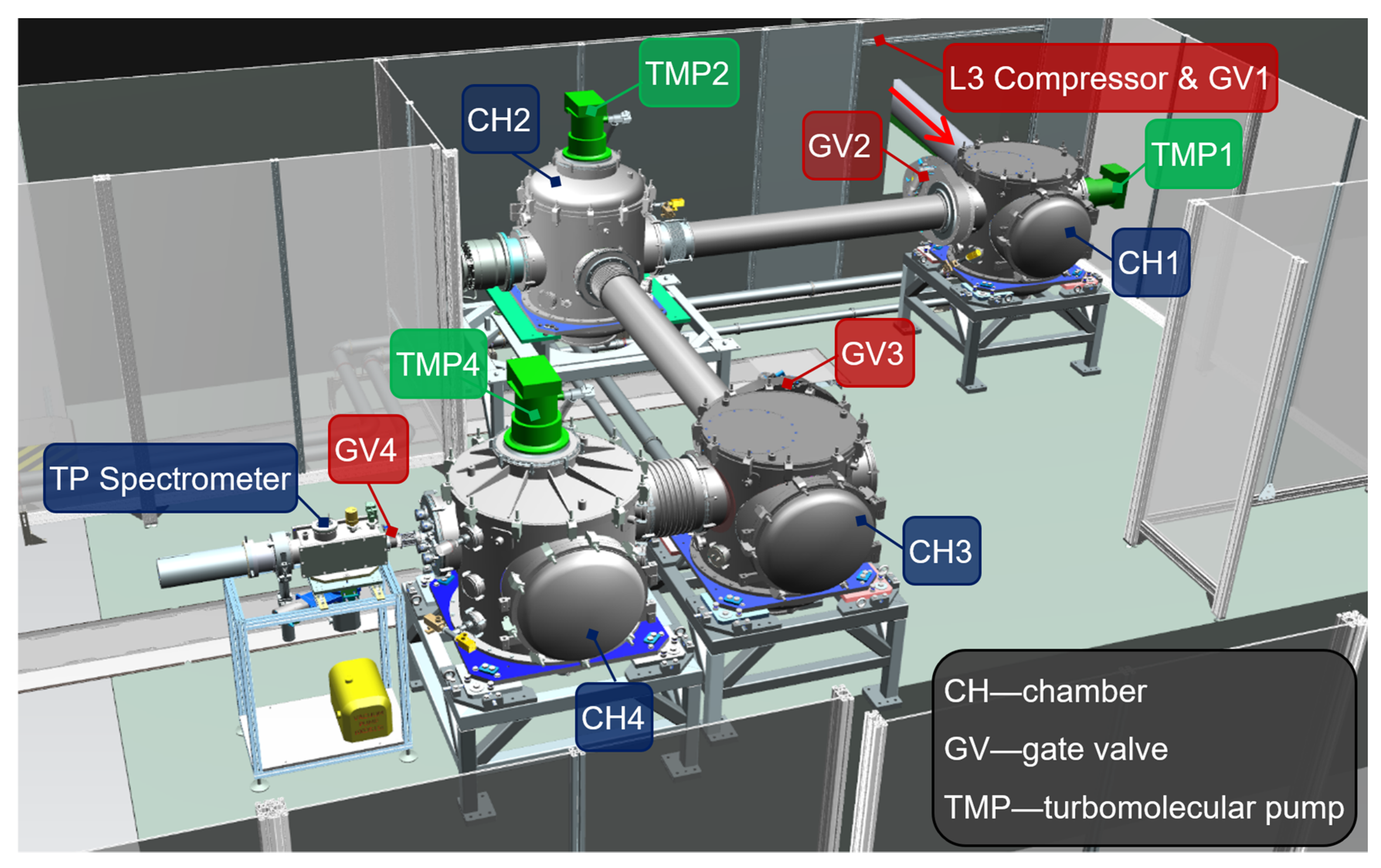
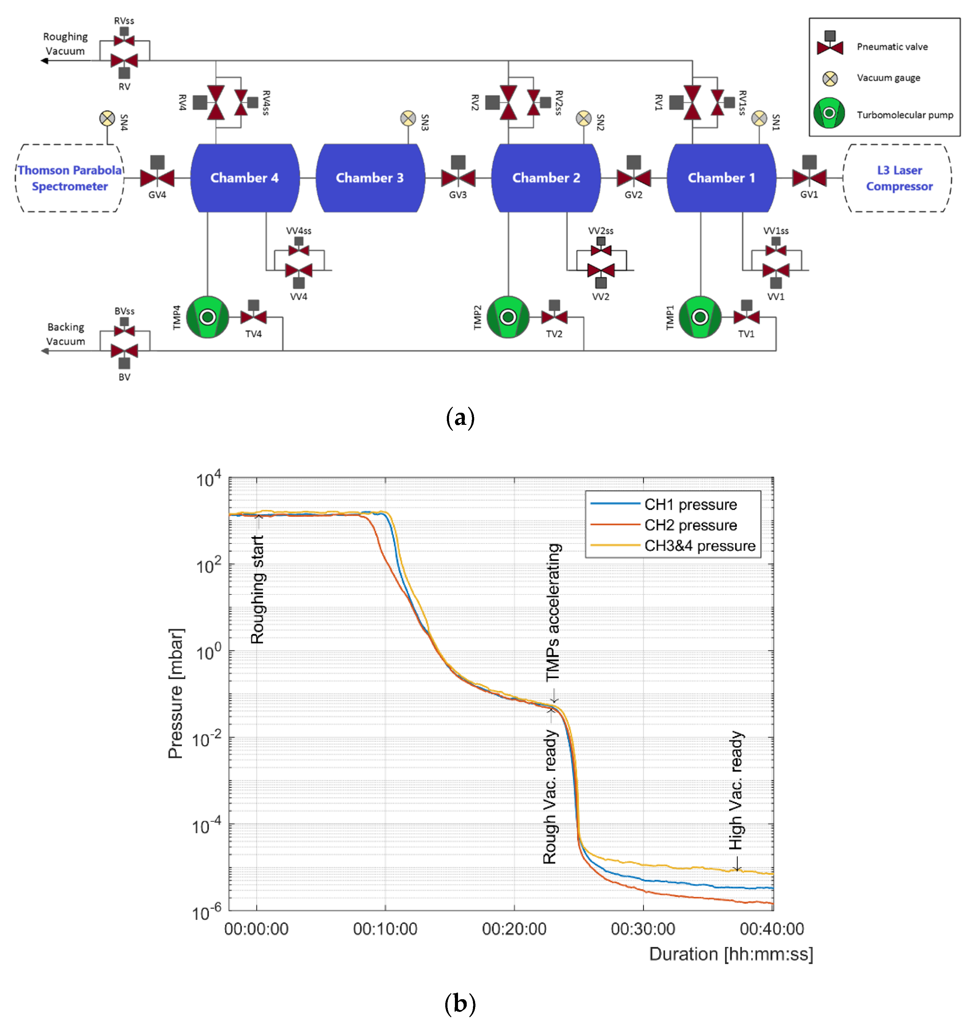
2. Vacuum and Control Systems

The TERESA target area is located inside the L2 laser hall at the ELI Beamlines laser floor, which is right next to the L3 laser hall. This location is advantageous due to a short beam path and a simple vacuum connection to the L3 compressor output. TERESA is designed to perform experiments at high vacuum (~10−6 mbar). Its vacuum system consists of four interconnected chambers (Figure 1). The first two mainly serve the purpose of laser beam transport, while the next two accommodate focusing optics, laser-target interaction and various diagnostics.
A schematic of the TERESA vacuum system is shown in Figure 2a. TERESA is serviced by two dedicated central vacuum lines: the roughing line is used to pump the system from atmospheric pressure down to the rough vacuum level, sufficient to start the Turbomolecular Pumps (TMPs), and the backing line supports operation of the TMPs at the high vacuum level. The total volume of the TERESA vacuum system is about 3 m3. Chambers 1, 2 and 4 are equipped with maglev turbomolecular pumps with a total pumping speed of about 3500 l/s. Pneumatic gate valves 1–4 are used to isolate the chambers from one another, creating autonomous sections that can be pumped down or vented independently. As a result, interconnection of adjacent chambers is not allowed until the high vacuum state is reached for both. A typical pump-down graph (Figure 2b) shows the pumping duration from atmosphere to high vacuum (<10−5 mbar) of less than 40 min, for a typical TERESA setup. However, these dynamics may vary depending on the chamber content and user requirements. In general, one full venting–pumping cycle takes less than an hour.
A stable and efficient operation of the vacuum system is crucial for maintaining the laser beam quality down to the interaction point at the target, after each venting–pumping cycle. The TERESA Vacuum Control System (VCS) is designed to achieve an optimal balance between operational flexibility and machine safety—protection for vacuum equipment and sensitive diagnostics. In order to meet the requirements of reliable and adaptive control, the VCS is based on a Programmable Logic Controller (PLC), which interprets the readings of vacuum gauges and other relevant system parameters. The operation of the VCS is semi-automatic: the PLC maintains the current state of the system, while a transition between different system states needs a manual user request.

3. Laser Parameters and Beam Transport

The laser beam provided to TERESA is a circular sub-aperture of the L3-HAPLS laser (super-Gaussian of 30th order, square beam 250 × 250 mm2) with a diameter of 90 mm (at 1/e2), and maximum pulse energy of 1.3 J (~20 mJ/cm2, at present). Ultrashort pulses with a central wavelength of 810 nm and duration < 30 fs (FWHM) are generated by a titanium-doped sapphire oscillator and amplified in a series of titanium-doped sapphire amplifiers. The laser can operate at a repetition rate of 10 Hz thanks to its DPSSL (diode-pumped solid-state laser) pump laser and a specially designed cooling of the Ti:Sapphire crystals [5]; however, the maximum repetition rate used for experiments at TERESA was 3.3 Hz.
The TERESA laser beam transport is equipped with gold-coated mirrors (from 6” to 8” in diameter), each possessing a reflectivity of 94%. It allows for the delivery of 1 J of laser energy onto the target. At the pulse duration of 30 fs (FWHM), the laser peak power on the target is about 30 TW. The beam throughout the optical system and at the target is p-polarized. TERESA is designed to work with two interchangeable sets of focusing optics (Figure 3). Depending on the experimental demand, an Off-Axis Parabola (OAP) with the focal length of either 330 mm (~f/3.7, short-focus, typical for solid targets) or 1200 mm (~f/13, long-focus, typical for gas targets) can be installed.
Two main alignment beams are available at TERESA:
  • Low-power mode of the L3 laser (~µJ energy level, 30 fs, 100 Hz rep. rate);
  • CW laser, propagating through the same beam path (785 nm, 130 mW, ~1 mm beam size).
Additionally, there are two laser diodes, visible and near-infrared (VIS and NIR), placed in chamber 1. They can be coaligned with the L3 laser and used as local references. In order to maintain the beam path aligned, the following procedure is established: the pointing of the alignment beam at each turning mirror is checked and corrected by tip/tilt of the previous mirror. For this, retractable ground glass alignment disks are set on linear positioners before each flat mirror. The beam position is then visualized using compact CCD cameras, sealed in hermetic air pockets, directed at the respective references. For the L3 laser focus and target alignment purposes, a retractable monitoring system with 10x optical magnification is set in the interaction chamber (Figure 4). It shows that the focal spot is very stable with linear fluctuation within ±1.6 µm (RMS), which gives a pointing stability of ±4.8 µrad (RMS). The OAP mount has 5 degrees of freedom (xyz + tip/tilt). Every motion mentioned above is motorized and can be performed remotely at high vacuum.
The short-focus OAP allows one to get an experimental focal spot diameter of 3.8 ± 0.1 μm (FWHM, see Figure 5a), which falls within the 1.3 margin from the diffraction-limited performance (3.1 µm at FWHM, see Figure 5b). Approximately 80% of the delivered laser energy is encircled in a 6.4-μm spot (1/e2 diameter of the focused beam). A conservative estimation of the laser intensity on target for the short-focus OAP gives a value of about 5 × 10¹⁹ W/cm2. Lower intensity values can be obtained by either decreasing the energy at the laser output or defocusing the beam with respect to the interaction point by moving the OAP along the optical axis. The long-focus OAP would allow one to get a focal spot diameter of about 11 μm at FWHM, as shown by the optical simulation output in Figure 5c.

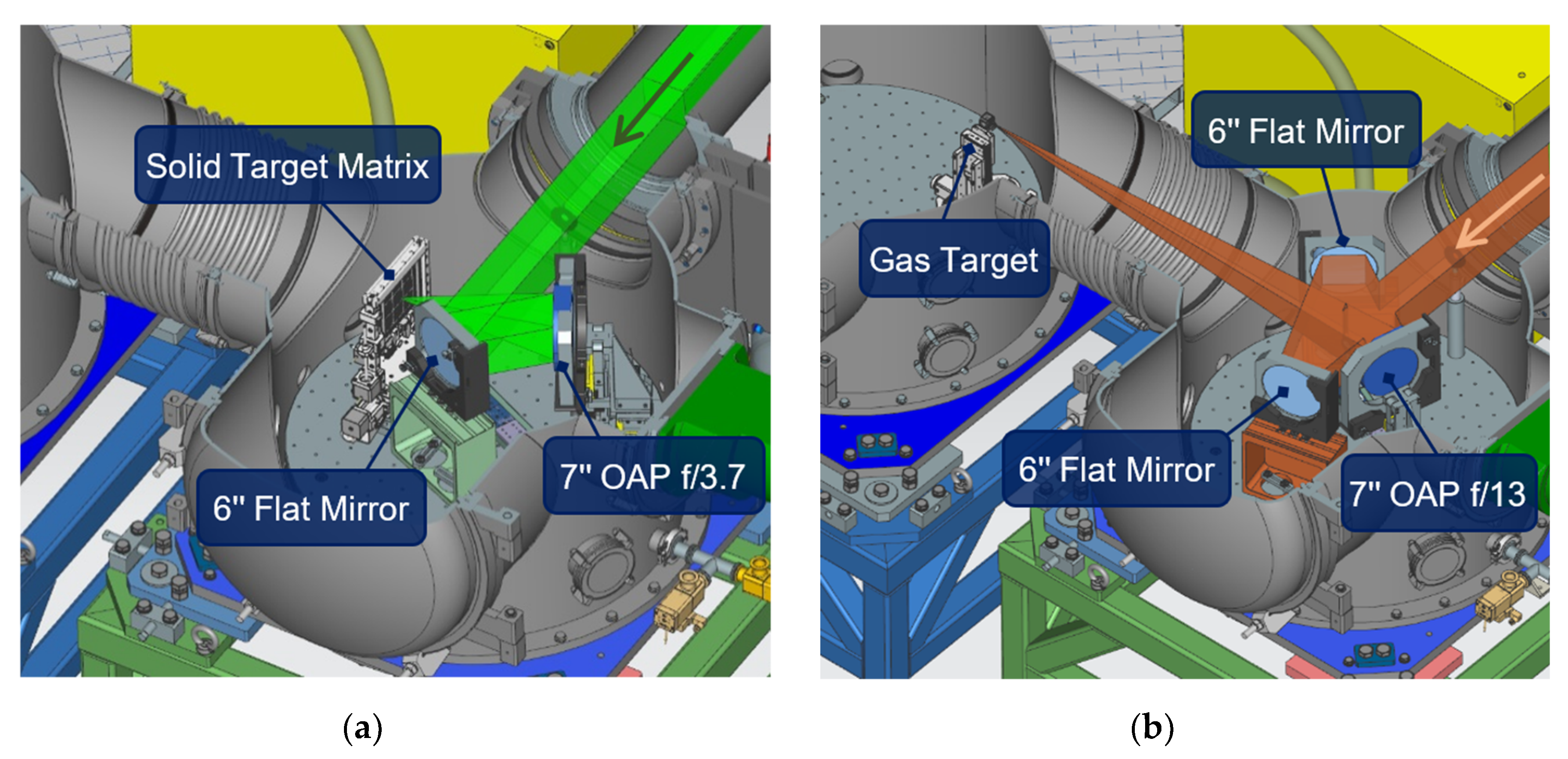
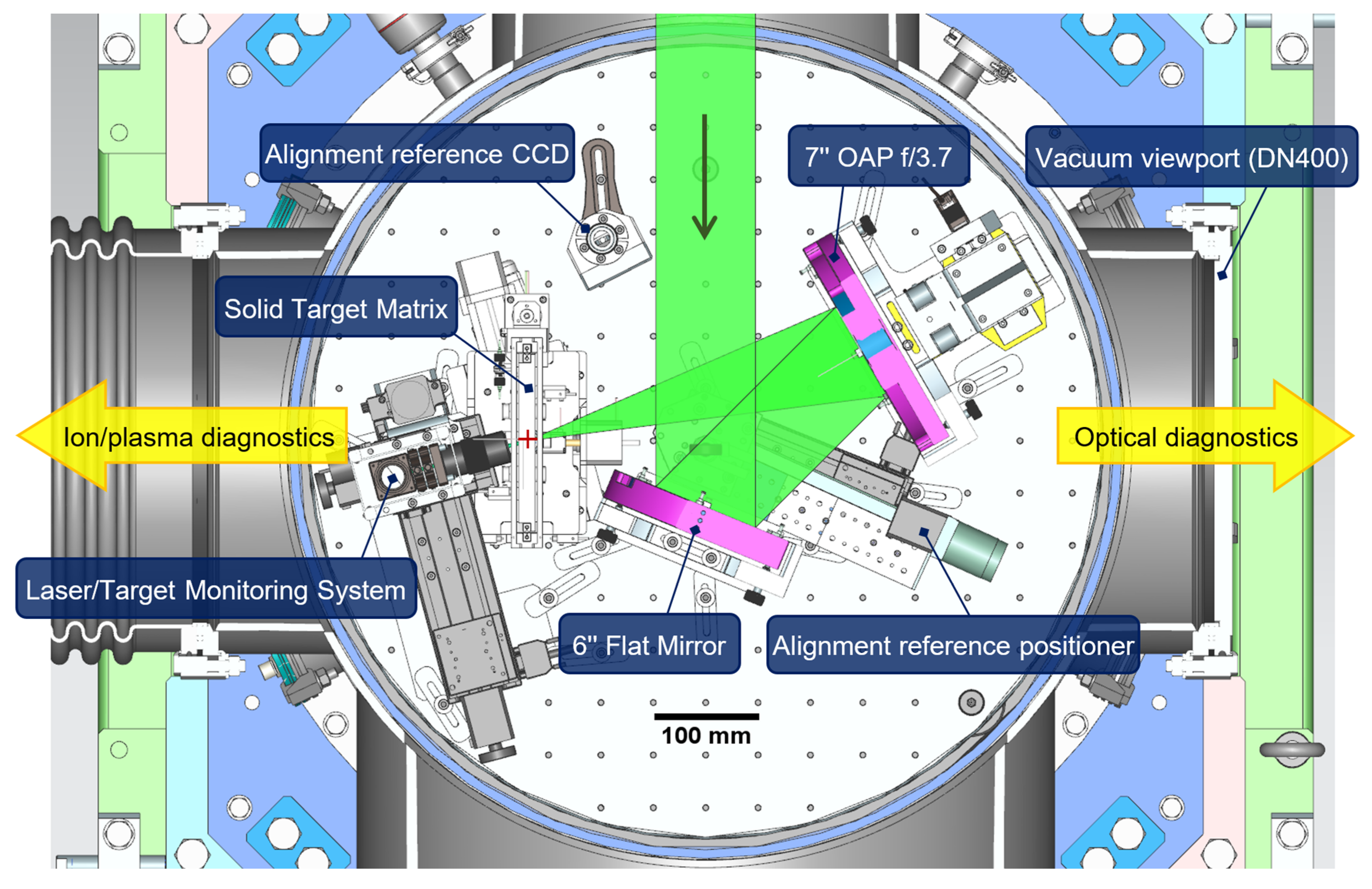
4. Available Diagnostics and Target Systems

The target area is equipped with active and passive particle diagnostics, such as Thomson Parabola (TP) spectrometer, Time-of-Flight (TOF) ion detectors, LANEX-screens, radiochromic film and solid-state nuclear track detectors. As an example, raw images acquired by the ion diagnostics, namely, a TP spectrometer snapshot showing protons and carbon ions, and an ion TOF signal recorded by a diamond detector and a fast oscilloscope, are shown in Figure 6a,b. The raw image of an accelerated electron beam recorded by a LANEX screen and a CCD camera is shown in Figure 6c.
Additionally, real-time gamma-ray spectroscopy can be carried out by the means of photomultiplier detectors and an in-house developed scintillator-based electromagnetic calorimeter. The electromagnetic calorimeter is designed for detection of high-energy photons (from tens of keV up to tens of MeV) at high repetition rate (up to 50 Hz) [9]. It comprises an array of crystals, composed of two types of scintillating materials (EJ-200 and BGO) with the goal to separate the two typical plasma electron temperatures. The readout of the scintillation is performed by a CMOS camera, which reduces the electromagnetic pulse effects on the signal extraction. Its typical signal output can be found in Figure 6d.
Available optical diagnostics include probing methods (shadowgraphy and interferometry, with the option of using a BBO (beta barium borate) crystal for the purpose of frequency doubling), VIS spectrometry and imaging techniques. The optical probe allows one to get a sideview image of a free-standing flat target or a gas target, at various times before or after the arrival of the main pulse. It can provide a valuable insight into the state of the target, for instance detecting pre-plasma formation or target pre-expansion induced by the laser pulse precursors. The optical probing line at TERESA uses a fraction of the main beam, picked up from its bottom edge by a beam splitter at the entrance to the experimental chamber. Thus, the resulting probe has the same spectral and temporal characteristics as the main laser pulse. The probe is directed to an optical delay line before it reaches the interaction point, propagating along the target surface. Default settings of the probing line provide a delay of ±33 ps with respect to the main laser pulse arrival. The interaction point is then imaged by an achromatic doublet, resulting in 5× magnification, and transferred one-to-one with another lens onto a CCD camera sensor outside the chamber, providing a shadowgraphy image. The linear polarization of the probing beam is orthogonal with respect to that of the main pulse, which allows one to partially filter the scattered light from the laser–target interaction by using a beam polarizer. In addition, a Wollaston prism and a polarizer can be inserted into the beam path, creating a Nomarski interferometer, which enables quantitative analysis of the interaction point density [10]. Optical schemes for the shadowgraphy and interferometry setups are shown in Figure 7a, while Figure 7b depicts an interferometry image of the interaction point, marked by the reference tip and illuminated by the focused beam, acquired in the process of alignment.
A commercial optical fiber spectrometer is also readily available as a diagnostics tool. It allows one to measure the UV-NIR spectrum (200–1100 nm) of the laser light reflected by the target as well as certain high-order harmonics generated during the interaction at the target surface.
TERESA can accommodate various target types for laser irradiation. Two target systems are available at TERESA by default: a target matrix with up to 900 solid targets (usually plastic or metallic foils) [6], operating at repetition rates up to 1 Hz and a gas jet, operating with various gas types and pressures [7], as typically employed in laser wake-field electron acceleration, with special care taken over the total amount of gas released into the chamber to allow the target operation at 10 Hz. The list of targets that have been tested at TERESA includes not only conventional thin foils and gas targets, but also an innovative subsonic gas jet with a 100-µm long micro-capillary coupled to a blade and a fast gas-valve [11] and a cryogenic hydrogen ribbon delivery system [12]. A continuous effort is put on the development of reliable solutions for rapid target delivery, data acquisition and real-time data analysis, suitable for proton acceleration schemes at high repetition rates that were preliminary tested at TERESA up to 3.3 Hz [13,14].

5. Conclusions

During the commissioning phase in 2019, TERESA hosted four successful experimental campaigns focused on laser–plasma acceleration, with a total of 3528 laser shots fired over 42 days of laser operation (only 76 h of net shooting time). More than 97% of the shots were successful, both in terms of target hits and delivered laser parameters (energy, pulse duration). Figure 8 shows the laser shot statistics accumulated over the four campaigns using different targets (plastic and metal foils of various thickness, gas jets, and cryogenic hydrogen ribbons).
The operation of TERESA at ELI Beamlines represents a key milestone since it demonstrates the first set of experiments successfully carried out at relativistic laser intensities using over-critical and under-critical density plasma targets, along with online plasma diagnostics and data acquisition systems that can operate at a high repetition rate (10 Hz). The reliability of the laser pulses delivered by the L3-HAPLS laser during the TERESA campaigns is promising for the upcoming high-peak-power commissioning experiments at the PW target areas, which in turn shall place ELI Beamlines among the high-power laser facilities operating at the international level [15].
Furthermore, the TERESA target area will be available for ELI Beamlines personnel and future external users as a testbed facility where R&D solutions on innovative target delivery systems and laser–plasma diagnostics, operating at high repetition rate, will be investigated [16,17]. As an example, it is worth mentioning that recently an operation test of a debris-free, cryogenic hydrogen ribbon target has been successfully accomplished at TERESA with 3.3 Hz repetition rate, and the results will be published in a follow up paper [13].

Author Contributions

Conceptualization, D.M., T.L.; methodology, F.G., M.T., M.F.N.; software, M.T., T.C., S.S., K.M., J.A.N.; validation, M.T., F.G., D.M, T.L.; formal analysis, M.T., A.V., F.G., T.L.; investigation, all co-authors; resources, D.M, T.L.; data curation, M.T., A.V., F.G., C.M.L., G.M.G., M.N., T.L., D.M.; writing—original draft preparation, M.T., F.G., D.M., T.C., T.L., L.G. (Lorenzo Giuffrida), V.I., A.V.; writing—review and editing, all co-authors; visualization, M.T., F.G.; supervision, D.M., T.L., B.R., G.K.; project administration, D.M.; funding acquisition, D.M. All authors have read and agreed to the published version of the manuscript.

Funding

This research was funded by the Ministry of Education, Youth and Sports of the Czech Republic by the project No. LQ1606, and by the project “Advanced Research Using High Intensity Laser Produced Photons and Particles” (CZ.02.1.01/0.0/0.0/16_019/0000789).

Acknowledgments

This work was carried out within the Particle Acceleration by Laser Research Program (RP3) at ELI-Beamlines. The authors gratefully acknowledge Pavel Korous, Martin Laub, Lukas Brabec, Martin Bucka, Petr Voboril, Marek Rajdl, Petr Kemeny, Lubos Nims, Martin Tuma, Pavel Bakule, Birgit Plotzeneder, Antonin Fajstavr, Jakub Cerny, Milan Berta, Vojitech Gaman, Radek Horalek, Petr Mazurek, Roman Kuratko, Libor Tirol, Veronika Olsovcova, Roberto Versaci, David Horvath, Marek Bizdra, Roman Trunecek, Vojtech Stransky, Hana Manaskova, Petr Prochazka and Jaroslav Kaspar for the valuable technical support provided.

Conflicts of Interest

The authors declare no conflict of interest.

References

  1. Macchi, A.; Borghesi, M.; Passoni, M. Ion acceleration by superintense laser-plasma interaction. Rev. Mod. Phys. 2013, 85, 751–793. [Google Scholar] [CrossRef] [Green Version]
  2. Esarey, E.; Schroeder, C.B.; Leemans, W.P. Physics of laser-driven plasma-based electron accelerators. Rev. Mod. Phys. 2009, 81, 1229–1285. [Google Scholar] [CrossRef]
  3. Mourou, G.A.; Korn, G.; Sandner, W.; Collier, J.L. ELI—Extreme Light Infrastructure Whitebook: Science and Technology with Ultra-Intense Lasers; THOSS Media GmbH: Berlin, Germany, 2011. [Google Scholar]
  4. Rus, B.; Batysta, F.; Čáp, J.; Divoký, M.; Fibrich, M.; Griffiths, M.; Haley, R.; Havlíček, T.; Hlavác, M.; Hřebíček, J.; et al. Outline of the ELI-Beamlines Facility; Proc. SPIE 8080, Diode-Pumped High Energy and High Power Lasers; ELI: Ultrarelativistic Laser-Matter Interactions and Petawatt Photonics; and HiPER: The European Pathway to Laser Energy, 808010 (9 June 2011). Available online: https://www.spiedigitallibrary.org/conference-proceedings-of-spie/8080/808010/Outline-of-the-ELI-Beamlines-facility/10.1117/12.890392.short?SSO=1 (accessed on 10 October 2020). [CrossRef]
  5. Sistrunk, E.; Spinka, T.; Bayramian, A.; Betts, S.; Bopp, R.; Buck, S.; Charron, K.; Cupal, J.; Deri, R.; Drouin, M.; et al. All Diode-Pumped, High-repetition-rate Advanced Petawatt Laser System (HAPLS). In Proceedings of the Conference on Lasers and Electro-Optics; OSA: Washington, DC, USA, 2017; p. STh1L.2. [Google Scholar]
  6. Margarone, D.; Cirrone, G.; Cuttone, G.; Amico, A.; Andò, L.; Borghesi, M.; Bulanov, S.; Bulanov, S.; Chatain, D.; Fajstavr, A.; et al. ELIMAIA: A Laser-Driven Ion Accelerator for Multidisciplinary Applications. Quantum Beam Sci. 2018, 2, 8. [Google Scholar] [CrossRef] [Green Version]
  7. Levato, T.; Bonora, S.; Grittani, G.M.; Lazzarini, C.M.; Nawaz, M.F.; Nevrkla, M.; Villanova, L.; Ziano, R.; Bassanese, S.; Bobrova, N.; et al. HELL: High-energy electrons by laser light, a user-oriented experimental platform at ELI beamlines. Appl. Sci. 2018, 8, 1565. [Google Scholar] [CrossRef] [Green Version]
  8. Weber, S.; Bechet, S.; Borneis, S.; Brabec, L.; Bučka, M.; Chacon-Golcher, E.; Ciappina, M.; DeMarco, M.; Fajstavr, A.; Falk, K.; et al. P3: An installation for high-energy density plasma physics and ultra-high intensity laser–matter interaction at ELI-Beamlines. Matter Radiat. Extrem. 2017, 2, 149–176. [Google Scholar] [CrossRef] [Green Version]
  9. Istokskaia, V.; Stransky, V.; Giuffrida, L.; Versaci, R.; Grepl, F.; Tryus, M.; Velyhan, A.; Krasa, J.; Krupka, M.; Singh, S.; et al. First tests of the scintillator-based electromagnetic calorimeter for the radiation and particles detection. J. Instrum. 2020. submitted. [Google Scholar]
  10. Benattar, R.; Popovics, C.; Sigel, R. Polarized light interferometer for laser fusion studies. Rev. Sci. Instrum. 1979, 50, 1583–1586. [Google Scholar] [CrossRef]
  11. Lorenz, S.; Grittani, G.; Chacon-Golcher, E.; Lazzarini, C.M.; Limpouch, J.; Nawaz, F.; Nevrkla, M.; Vilanova, L.; Levato, T. Characterization of supersonic and subsonic gas targets for laser wakefield electron acceleration experiments. Matter Radiat. Extrem. 2019, 4, 015401. [Google Scholar] [CrossRef] [Green Version]
  12. Margarone, D.; Velyhan, A.; Dostal, J.; Ullschmied, J.; Perin, J.P.; Chatain, D.; Garcia, S.; Bonnay, P.; Pisarczyk, T.; Dudzak, R.; et al. Proton Acceleration Driven by a Nanosecond Laser from a Cryogenic Thin Solid-Hydrogen Ribbon. Phys. Rev. X 2016, 6, 041030. [Google Scholar] [CrossRef] [Green Version]
  13. Chagovets, T.; Stancek, S.; Giuffrida, L.; Velyhan, A.; Tryus, M.; Grepl, F.; Istokskaia, V.; Kantarelou, V.; Wiste, T.; Hernandez, M.J.C.; et al. Automation of target delivery and diagnostic systems for high repetition rate laser-plasma acceleration and applications. Rev. Sci. Instrum. 2020. submitted. [Google Scholar]
  14. Levato, T.; Goncalves, L.V.; Giannini, V. Laser-Plasma Accelerated Protons: Energy increase in Gas-Mixture Using High Mass Number Atomic Species. Fluids 2019, 4, 150. [Google Scholar] [CrossRef] [Green Version]
  15. Danson, C.N.; Haefner, C.; Bromage, J.; Butcher, T.; Chanteloup, J.C.F.; Chowdhury, E.A.; Galvanauskas, A.; Gizzi, L.A.; Hein, J.; Hillier, D.I.; et al. Petawatt and exawatt class lasers worldwide. High Power Laser Sci. Eng. 2019, 7. [Google Scholar] [CrossRef]
  16. Prencipe, I.; Fuchs, J.; Pascarelli, S.; Schumacher, D.W.; Stephens, R.B.; Alexander, N.B.; Briggs, R.; Büscher, M.; Cernaianu, M.O.; Choukourov, A.; et al. Targets for high repetition rate laser facilities: Needs, challenges and perspectives. High Power Laser Sci. Eng. 2017, 5, 1–31. [Google Scholar] [CrossRef] [Green Version]
  17. Bolton, P.R.; Borghesi, M.; Brenner, C.; Carroll, D.C.; De Martinis, C.; Fiorini, F.; Flacco, A.; Floquet, V.; Fuchs, J.; Gallegos, P.; et al. Instrumentation for diagnostics and control of laser-accelerated proton (ion) beams. Phys. Med. 2014, 30, 255–270. [Google Scholar] [CrossRef] [PubMed] [Green Version]
Figure 1. General view of TEstbed for high REpetition-rate Sources of Accelerated particles (TERESA) Target Area in the L2 Hall. Arrow indicates the incoming laser beam.
Qubs 04 00037 g001
Figure 2. (a) Schematic of the TERESA vacuum system. (b) Typical graph of TERESA pump-down.
Qubs 04 00037 g002
Figure 3. Schematic of two experimental setups at TERESA: (a) solid target, short-focus Off-Axis Parabola (OAP) f/3.7 and (b) gas target, long-focus OAP f/13. Arrows indicate the incoming L3 laser beam.
Qubs 04 00037 g003
Figure 4. Top view of the experimental chamber setup (solid target, short-focus OAP f/3.7, angle-of-incidence 15°). Interaction point is marked by the red cross.
Qubs 04 00037 g004
Figure 5. (a) Focal spot obtained experimentally at a low power of the L3 laser with the short-focus OAP f/3.7 (CCD image and cross-section profiles); VirtualLab optical simulations of the focal spot for (b) OAP f/3.7 and (c) OAP f/13.
Qubs 04 00037 g005
Figure 6. Typical (raw) signals acquired by TERESA diagnostics: (a) Thomson Parabola (TP) ion beam snapshot, (b) Time-of-Flight (TOF) ion beam signal, (c) LANEX-screen-based electron beam image, (d) scintillation signal of the electromagnetic calorimeter.
Qubs 04 00037 g006
Figure 7. (a) Scheme of the optical probing setup in shadowgraphy and interferometry mode. (b) Interferometry image of the interaction point acquired during the optical probe alignment.
Qubs 04 00037 g007
Figure 8. Statistics of laser shots and targets used at TERESA in 2019.
Qubs 04 00037 g008
Publisher’s Note: MDPI stays neutral with regard to jurisdictional claims in published maps and institutional affiliations.

