Article

A Pulse-Multiplication Proposal for MIRACLES, the Neutron TOF-Backscattering Instrument at the European Spallation Source

by
Félix J. Villacorta
1,*,
Heloisa N. Bordallo
2,3 and
Masatoshi Arai
3
1
ESS-Bilbao, Parque Científico y Tecnológico Bizkaia Nave 201, 48170 Zamudio, Spain
2
Niels Bohr Institute, University of Copenhagen, Universitetsparken 5, 2100 Copenhagen, Denmark
3
European Spallation Source ESS ERIC, P.O. Box 176, SE-22100 Lund, Sweden
*
Author to whom correspondence should be addressed.
Submission received: 4 December 2020 / Revised: 8 January 2021 / Accepted: 11 January 2021 / Published: 14 January 2021
(This article belongs to the Special Issue New Trends in Neutron Instrumentation)

Abstract

:
The fixed-energy window scan approach, for both elastic and inelastic modes, is a valuable tool to discriminate between motions activated when dynamical phase transitions occur in a sample as a function of time, temperature, pressure, electrical field or illumination. Considering that, on one hand, such variations can generate a weak signal, and on the other, high data throughput makes it possible to screen many samples during a beam time, pulse multiplication is an ideal strategy to optimize the intensity of the analyzed signal. To ensure this capability, a proposal for a future upgrade of MIRACLES, the neutron time-of-flight backscattering spectrometer at the European Spallation Source (ESS) under construction in Lund, is reported in this article. The concept for a new chopper layout relies on the extraction of several elastic pulses, ensuring an increase in the neutron total elastic intensity hitting the sample. This proposal can be extended to the inelastic counterpart. The premise is to maintain the original beamline layout without modification, either of the guide sections or of the current chopper layout of MIRACLES, thereby guaranteeing that minimal changes and impact will occur during the proposed upgrade. However, this also presents a significant challenge, namely, to achieve an efficient pulse multiplication within the width and the length of the guide and within the rising/decay time of the pulses. With the concept presented here, an increase in elastic intensity by a factor of 2.8 was obtained. This is analogous to performing elastic fixed window (EFW) measurements with an ESS source operating at 14 MW, widening considerably the performance capabilities of MIRACLES. The knowledge generated here is also valuable for the design of scientific instruments for the next generation of low-energy, accelerator-driven neutron sources.

1. Introduction

In a neutron backscattering experiment, the ability to probe collective dynamics at the picosecond timescale through inelastic neutron scattering (INS) depends mainly on the dynamic range delivered by the instrument (Figure 1a). On the other hand, features characterizing slow dynamics are described by analyzing variations in the quasielastic neutron scattering (QENS) signal. Experimentally, a QENS dataset is described by a set of scattering functions, S(Q,ω), depending on the momentum transfer Q and energy transfer ħω, which manifests itself as a series of peaks centered at ω = 0 [1]. The observation of these microscopic motions depends on the energy resolution offered by the instrument, and the slowest observation time is set by the width of the resolution of the instrument.
Another type of neutron scattering experiment uses the elastic fixed window (EFW) approach, where the analysis of the structure factor, S(Q,ω ≈ 0), as a function of Q, provides a global view of the dynamics. Hence, an indication of motions occurring within or outside the timescale provided by the instrument resolution can easily be obtained. In other words, during an EFW scan, all motions faster than the resolution-time can be quantified by the loss of elastic scattering intensity [2]. EFW scans resemble a differential scanning calorimeter (DSC) graph, and are ideal for revealing variations in the dynamics of a system, e.g., the temperature at which the dynamics under observation ‘enters and exits’ (viz. is observable) the time window of the neutron spectrometer. This can be significantly useful when dealing with the dynamics timescale of, e.g., proteins [3], drug delivery [4,5] or energy materials [6,7]. This approach is also used to perform inelastic fixed window (IFW) scans to boost the observation of weak inelastic features [8,9], confirming that both EFW and IFW measurements as a function of temperature are widely used in neutron spectrometers [10,11,12].
MIRACLES, the future neutron time-of-flight backscattering spectrometer at the European Spallation Source under construction in Lund [13], is currently in the detailed design phase and will have a simple and versatile chopper cascade that allows a flexible selection of the energy resolution [14,15,16]. A counter-rotating double-disk (PWD) chopper, with one slit of aperture of α = 12°, will act as a pulse-shaping chopper to modulate the long ESS pulse (ΔTESS = 2.857 ms), allowing pulse durations of as little as 60 μs. This will yield a tunable energy resolution ranging from δ(ħω) ~1.5 μeV to almost 50 μeV, thus covering a wide observation time for the dynamics under study, from the nanosecond to the tens of picoseconds range. This flexibility will also be extended to the tunability of the incident energy to carry out inelastic neutron scattering (INS) experiments covering a wide range of energy transfer, i.e., about 20 meV. Additionally, a pulse selection (PS) chopper, with one slit opening of α = 15°, to extract one pulse from every ESS pulse (with a frequency of 14 Hz), and a bandwidth (BW/FO) chopper, with slit aperture of α = 110°, will give final shape to the neutron pulse arriving at the sample (Figure 1b,c), rejecting long wavelength contaminating neutrons in the high-resolution modes and preventing undesirable frame overlap between pulses at the sample position in the high flux mode.
With the current chopper cascade, in high resolution modes, MIRACLES will use only 60/2857 = 2.1% of the suitable neutrons with elastic energy (within the “elastic band”); the remaining 97.9% are simply filtered out. This makes fixed energy window scan measurements ineffective. To solve this drawback, we present a detailed analysis of an upgrade option for MIRACLES, aiming for a significant increase in the total intensity for fixed-energy window scan measurements, through a pulse multiplication strategy, an idea firstly outlined by Arai et al. [17] for EFW scans.
In previous works, pulse multiplication applied to a neutron TOF-backscattering spectrometer was oriented to enlarge its dynamic range for inelastic neutron scattering. For example, an extension from ~100 μeV to several hundreds of μeV has been proposed for DNA, the TOF-backscattering spectrometer in J-PARC [18]. However, for MIRACLES, the long pulse plus the low repetition rate provided by ESS, together with the length of the instrument (~160 m beamline), already provide a very wide dynamic range, i.e., Δλ ~1.7 Å (ΔE ≈ 1.1 meV around λ = 6.27 Å). Therefore, the function of a pulse multiplication here is devoted to enhancing the final elastic flux at the sample position. With this upgrade, a significant capitalization of the delivered elastic neutrons with a concomitant boost in the ability to distinguish between motions is granted.

2. Materials and Methods

The main boundary condition of the reported simulation results after introducing the capability of performing pulse-multiplication in MIRACLES is to minimize the impact of the proposed upgrade to the current instrument design. Currently (end of 2020), the neutron beamline of the MIRACLES system is at its detailed design phase; this means that the conceptual layout is complete, but some minor changes, related to gaps and interfaces, can still be implemented. Thus, for the proposed upgrade, we have kept in mind that the implementation of the new choppers should be carried out in existing chopper pits or with a minimal modification of one short guide unit, in order to maintain the total length of the beamline. Other considerations are described in the following subsections.
Accordingly, the final goal of this work was to keep the current guide layout and chopper cascade almost unchanged. To achieve this, we started by performing analytical calculations to determine the new pulse structure as follows. First, the time of flight (TOF) structure of the chopper cascade was obtained through analytical calculations, supported using a Matlab script [19], when complexity increases. Subsequently, Monte Carlo ray-tracing calculations using McStas (version 2.4) [20] were systematically performed, with the ESS_butterfly moderator component [21] modelling the source. For all explored configurations, eight ESS pulses were simulated. Moreover, based on the previous MIRACLES model [14], single-disk choppers and counter-rotating, double-disk choppers were introduced along the beam line using the DiskChopper component. The pulse structure was monitored using different detectors and monitor components (L_monitor and TOF_monitor) placed before and after every chopper, as well as in additional positions, like the beam extraction and the focusing guide segments, so that information about the TOF structure and wavelength-energy distribution, respectively, could be accurately examined. All simulations and calculations were carried out applying elastic energy (E = 2.081 meV; λ = 6.27 Å), but conclusions can be extended to tune any other energy to explore inelastic features.
In particular, the following considerations, related to the pulse shape and to the design of the chopper cascade, were also carefully taken into account:
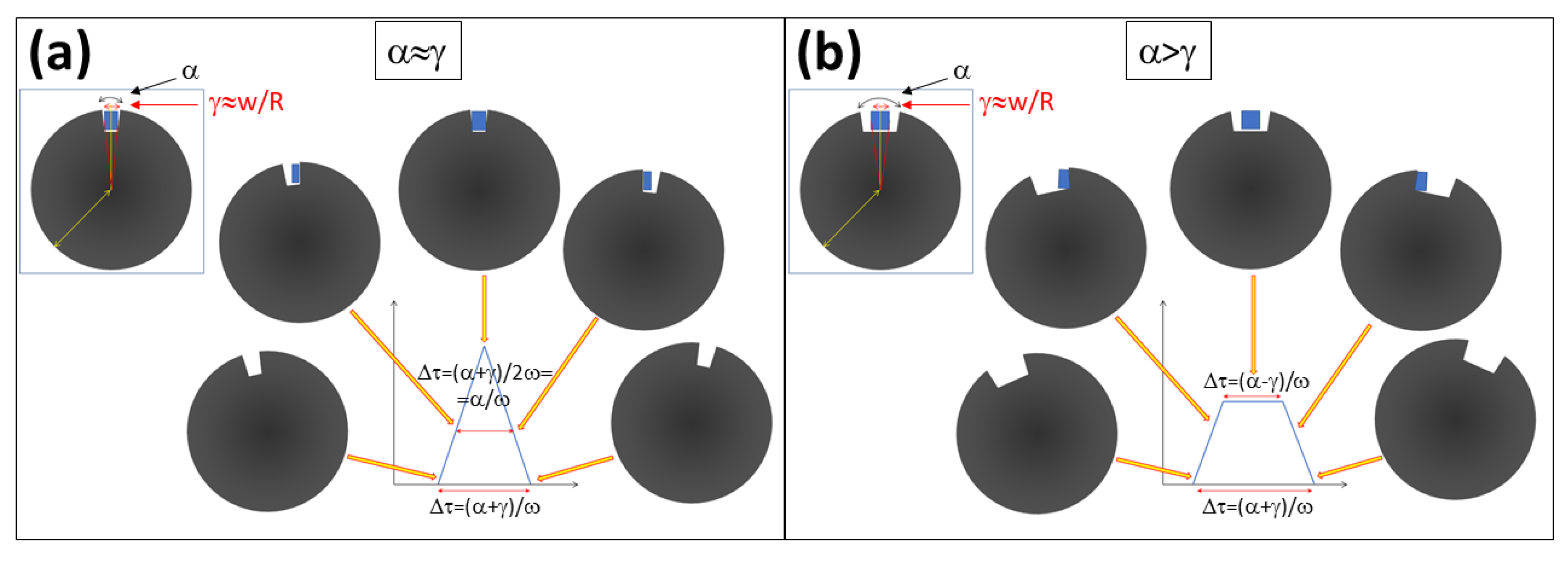
  • Pulse shape: Triangular (where the chopper slit opening angle, α, is of the same dimensions as the guide opening angle, γ; thus, α = γ) and trapezoidal (where α > γ) pulse shapes were considered in the calculations; see Figure 2. We note that in the latter case, the chopper must run faster to keep the same full width at half-maximum (FWHM) of the pulse and reduce its rise/decay time.
  • Guide opening angle: the angular projection of the guide with respect to the center of the choppers in the straight section (downstream from the curve) ranges from γ = 17° (in the position of the BW/FO chopper) to γ = 21° (in the 90-m straight section before the focusing guide).
  • Single chopper opening times: For single disks, the total opening time is given by Δτtot = ( α   +   γ ) ω , while for trapezoidal pulses, the rise/decay time is: ΔτR/D = γ ω .
  • Double chopper configuration opening times: For counter-rotating double disk choppers, the energy resolution is determined by the FWHM opening times ΔτFWHM = α 2 ω , where ω = 2 π f angular velocity, in rad/s, and f is in Hz.
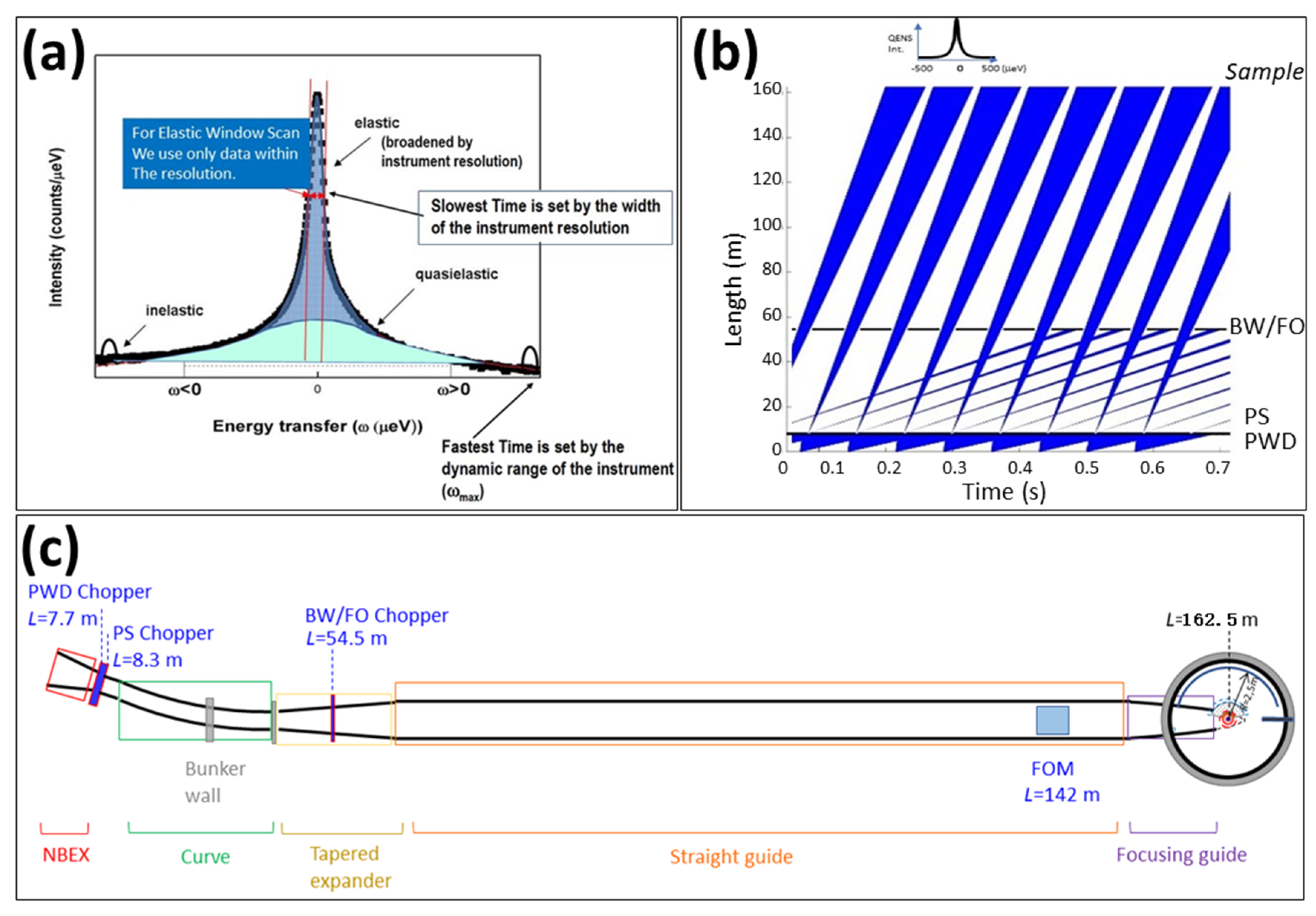
  • Energy resolution: In a neutron TOF-backscattering spectrometer, the contributions to the final energy resolution from the primary spectrometer, δEP, are mostly determined by the beam divergence, yielding a distribution of flight pathway lengths, ΔL, and a pulse size of Δτ: [22,23]
    δ E p = 2 E ( Δ L L ) 2 + ( Δ τ t T O F ) 2  
    where E is the energy selected, L is the length of the primary spectrometer from source to sample, and τ is its neutron flight time.

3. Results and Discussion

The strategy followed to obtain pulse multiplication has two main aspects. Firstly, preliminary simulations shall ensure a clean propagation of the “elastic energy band” from the source to the sample. This “elastic energy band” width is that of the ESS pulse duration (ΔTESS = 2.86 ms).
After that, the second step consisted of the multiplication of the pulses to obtain shorter pulses of the same neutron energy to qualitatively increase the total flux at the selected neutron energy while maintaining the high energy resolution capability of the instrument.
It should be highlighted that the calculations, carried out using elastic energy, can be extrapolated to select any energy in the cold neutron range.

3.1. First Step: Propagating the Neutron Elastic Band

The first idea for obtaining a clean pulse multiplication profile was to use the MIRACLES high-flux mode, i.e., with one of the PWD disks parked and the other running at 14 Hz, which delivered a symmetric triangular pulse with Δτ ~ 2.4 ms, that almost equaled the ESS pulse duration. After that, additional slow bandwidth choppers distributed along the beamline were integrated to maintain the elastic energy bandwidth with a filtering functionality (i.e., reducing the transmission of neutrons with different energies). The first of these choppers was the bandwidth BW/FO chopper, already in the current design. Since this Al chopper can run faster, an opening time of approximately the ESS pulse duration can be achieved (see Figure 3a). At f = 70 Hz and with a guide projection of γ = 17°, an opening time of ΔτFWHM = 2.5 ms was obtained.
Then, a second bandwidth chopper (named monochromating chopper, MC1; see Figure 3a) was required to select the main pulse that delivers the “elastic energy band” and suppress the unwanted neutrons. This chopper had to be located right after the BW/FO chopper at LBW/FO = 54.5 m, but before the position where the pulses delivered by this BW/FO bandwidth chopper overlapped, i.e., Loverlap = 62.3 m. The eventual position used in the Monte Carlo calculations was just downstream of the BW/FO chopper, at LMC1 = 54.9 m. Afterwards, the selected band width propagated and expanded along the rest of the beamline. When the expansion became much larger than the elastic bandwidth, a second monochromating chopper (MC2 chopper) was required. In this case and for practical purposes, MC2 was placed between the frame overlap mirror and the focusing guide (LMC2 = 145.3 m, see Figure 3a,b). We chose trapezoidal pulses for MC2 with a total opening time of ~2.8 ms by selecting slits of α = 45° with choppers running at f = 70 Hz; larger openings would increase the burst time and maximize flux, but at the expense of also releasing unwanted contaminant neutrons. Furthermore, the large width of the MIRACLES guide, mainly in the long straight section, resulted in large guide opening angles, γ (see Figure 2), and thus, the rise/decay times before and after the maximum flux plateau in such a trapezoidal version were not sufficiently abrupt, making a reduction in the transmission of the elastic neutrons unavoidable.

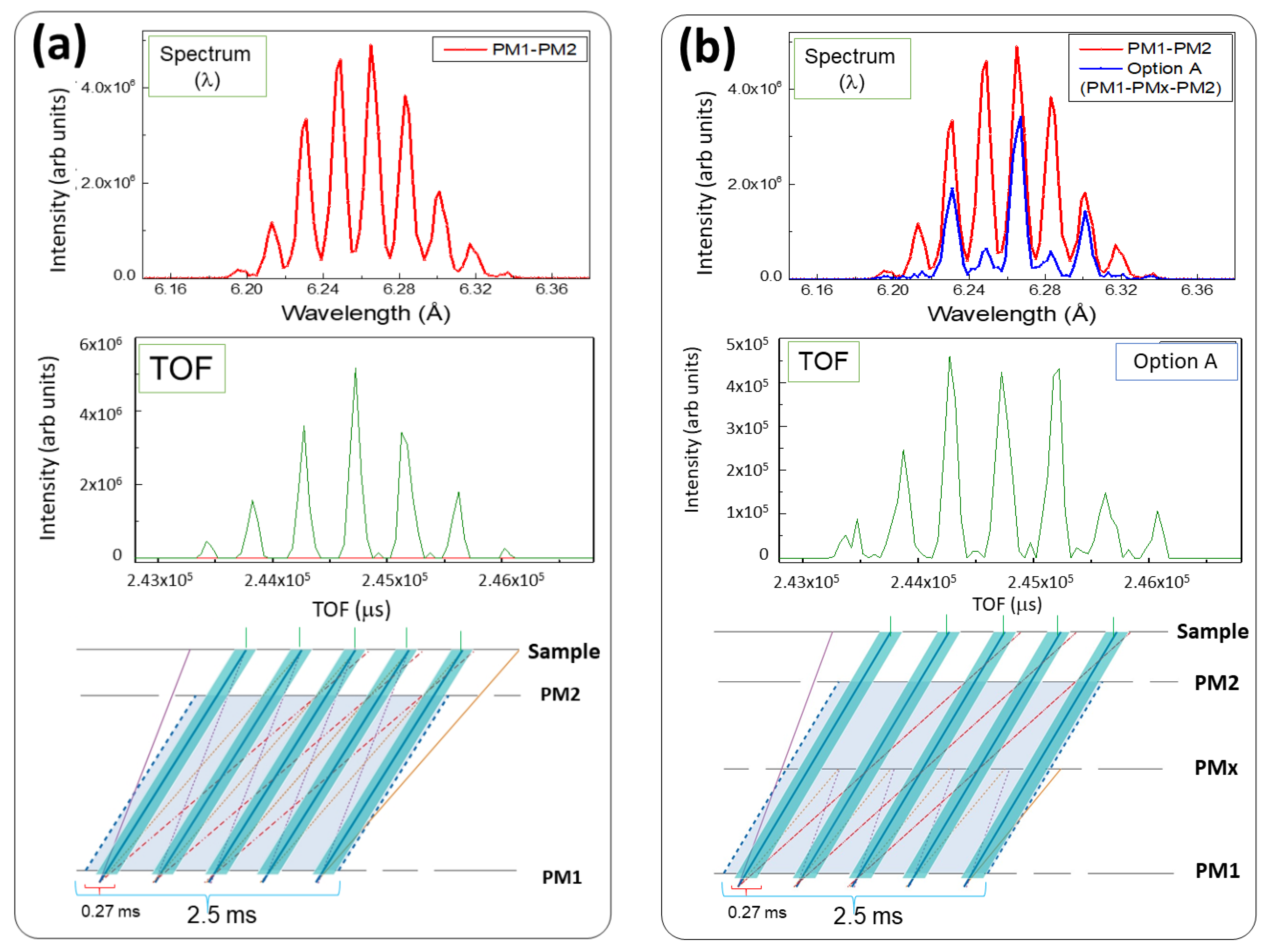
3.2. Second Step: Rationale for Pulse Multiplication
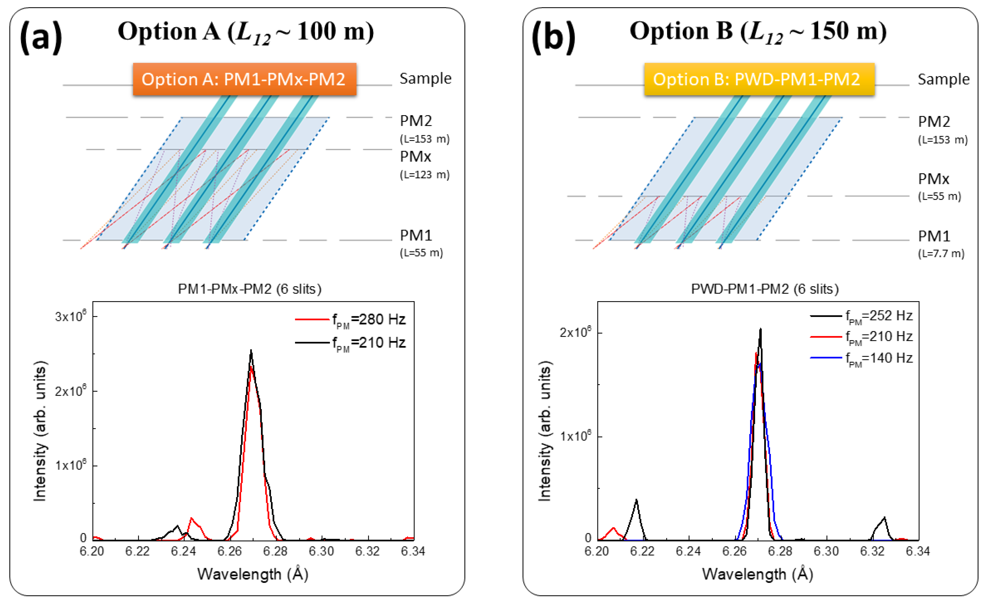
In addition, to extract high-resolution pulses from the elastic energy bandwidth, we needed at least two rapidly counter-rotating double-disk choppers, PM1 and PM2. The principle is the same as the double chopper spectrometer configuration [24], where these two choppers are appropriately phased with respect to each other to select the energy of the pulses (in this case, the elastic energy).
As a first approach, it was possible to extract two pulses in a long instrument like MIRACLES (~160 m). For instance, when the pulse shaping chopper was run at f ≥ 252 Hz, two slits allowed for a distance between pulses close to the ESS pulse width, i.e., ΔT ≤ 1.99 ms. In this case (Figure 4a), assuming a distance between the two fast PM choppers of L12 ~ 150 m, contamination pulses were transmitted at the same opening slots (Figure 4b), with an opening time of t ≤ 60 μs, energy resolution of δE ≤ 2 μeV, making them difficult to separate. This resulted in extra contributions to the elastic band (Figure 4c). However, the energy difference of those extra neutrons from the main elastic energy was about ±35 μeV, and the actual contamination after scattering by a typical sample, like water, was only 1/100 in comparison to the main elastic intensity. This was also distinguishable at a relaxed resolution (e.g., δE > 10 μeV). These results are compelling; however, the total elastic flux must be optimized in terms of intensity. Thus, to obtain an efficient yield from the pulse multiplication concept, more pulses ought to be extracted out of the elastic energy band. To do that, the number of slits had to be increased in the PM fast choppers, as discussed below.
The available energy resolution (as well as the final intensity at the sample position) [24] was then determined by the opening time of the choppers, the distance between the two fast choppers, L12 = LPMLPM1, and the distance between the last chopper LPM2 and the sample, L2S [25,26,27]. The PM2 chopper, acting as a resolution defining chopper, will be located at LPM2 ≈ 153 m, the closest possible place to the sample but before the start of the elliptical focusing guide. This was done because choppers occupy a space of several centimeters, leaving a gap in the guide that hampers the confinement of the neutrons; hence, the presence of choppers in places with high divergence (i.e., the final meters of a focusing guide) should be avoided. Moreover, installing a chopper module within the vessel is problematic, and no significant gain was observed.
As PM1 can be located at several positions, we selected two positions in order to make a comparison (see also a description of the proposed chopper cascades in Table 1):
(a)
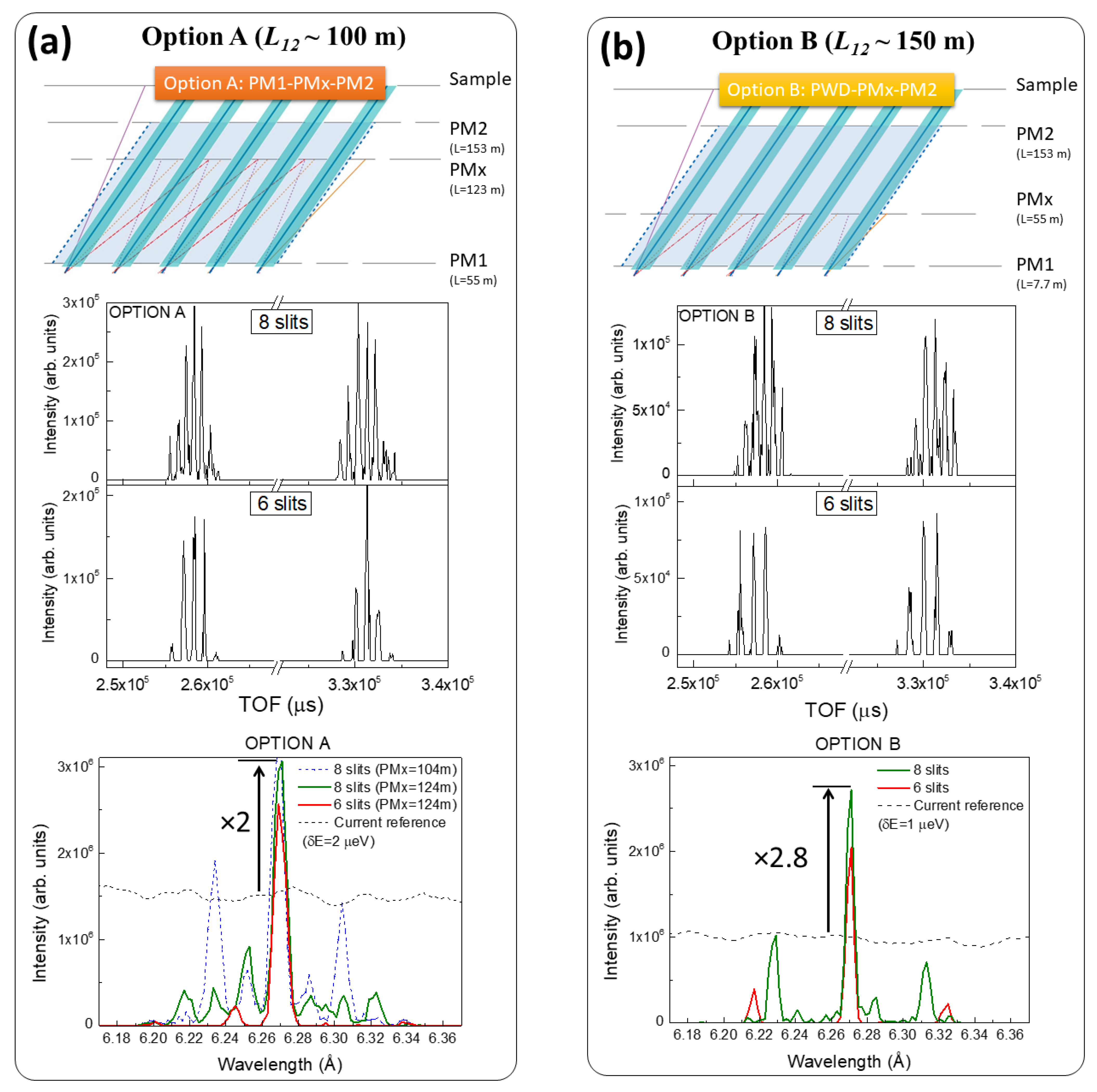
Option A: LPM1a = 55 m and L12 ~ 100 m, with the PWD pulse shaping chopper working as a bandwidth chopper and running as mentioned above (one disk parked, the other at f = 14 Hz, thus Δτ ~ 2.4 ms), PM1 was placed after the MC1 chopper. This was the most feasible option, since the MIRACLES current chopper cascade would not be modified, and installation of the PM1 chopper would take place outside the ESS bunker.
(b)
Option B: LPM1bLPWD = 7.7 m and L12 ~ 150 m) consisted of rendering the largest possible distance between the fast choppers, using the PWD pulse shaping chopper as the first pulse multiplication chopper (PWD≡PM1). This solution implies exchanging the single-slit PWD chopper for a multislit chopper within the bunker, resulting in pulse multiplication from the pulse shaping.

3.3. Third Step: Multislit Approach with Five Pulses

As a test bench for the multislit approach, the chopper layout of Option A (L12 ~ 100 m) could be used. To extract five pulses out of a band of Δτ ≈ 2.5 ms, a double-disk counter rotating chopper running at f = 280 Hz with eight equidistant slits of α = 27° was needed. The result was the delivery of five pulses with duration ΔτFWHM = 134 μs, and an equivalent frequency of f = 280 × 8 = 2240 Hz, thus, a period of T = 446 μs. A priori, a convenient phasing between PM1 and PM2 resulted in the efficient transmission of pulses through their adequate opening slots (see TOF graph in Figure 5a). However, the increasing number of slots also allowed the transmission of neutrons to occur with energies other than the elastic one that go through the same slot in PM1 but are transmitted by PM2 using the adjacent opening slots, giving a multichromatic quantized spectrum (see wavelength spectrum in Figure 5a).
These unwanted neutrons can be suppressed by introducing an intermediate chopper, labeled PMx, in phase with the other two fast choppers and capable of cutting out these narrow neutron bands. When the PMx chopper was placed equidistantly between both fast PM choppers (LPMx ~ 104 m), neutrons transmitted by the adjacent slot outside of the elastic energy resolution could be removed (see Figure 5b); however, contamination from the second adjacent slot persisted, caused by the slower neutrons that went through PM2 with opening times that were two slots after the elastic neutron slot (Figure 5b).
A strategy to maximize the rejection of contaminant neutrons consisted of displacing the middle chopper, PMx, to a position where both slower and faster neutrons could be cut. This implied that the filtering function of PMx should be maximized when this chopper was placed at LPMx ≈ LPM1 + 2/3·L12 ~ 123 m (see Table 2). This configuration resulted in an enhancement of the elastic intensity by a factor 2 when compared with the current wide spectrum (see Figure 6a) and a FWHM of δEFWHM ~ 4 μeV.
However, obtaining a clean elastic peak is challenging. Due to the large width of the MIRACLES guide (13 cm in the straight section) and assuming αγ, the apertures of the PM choppers in Option A were also large (α = 27° for trapezoidal pulses), and the use of eight slits resulted in a total opening time of 27 × 8/360 = 60%. A possible solution for a more efficient contaminant rejection consisted of using the double trumpet arrangement, with tapered guides, similar to NEAT [28] and LET [29], or using a needle-eye option with parabolic-elliptic guide profiles. Both strategies seek to reduce the guide section at the chopper position, and thus facilitate the implementation of a smaller slit width.
Additional calculations were carried out with a further displacement of the PMx chopper, to a position which represents a noninteger denominator (not LPMxLPM1 + 2/3·L12, but, e.g., LPMx ≈ LPM1 + 2/3.4·L12). With this subtle modification, it was analytically predicted that the PMx chopper would be able to block all contaminant neutrons, i.e., neutrons that do not have the elastic energy. However, we found that it was the case only if the slots were sufficiently small (i.e., sufficiently narrow), and therefore, that this modification was not simply applicable to the current geometry with the large aperture of the guide system.
A similar rationale was applied to Option B, utilizing a middle chopper introduced at LPMxLPM1 + 1/3·L12, viz. at the same position as PM1 in Option A, LPMx = LPM1a = 55 m. The chopper layout for both options is described in Table 2. Fast choppers in Option B were run at f = 252 Hz, yielding a FWHM of the elastic peak below δEFWHM ~ 2 μeV.
The results showed a 2.8× enhancement of the elastic flux at the sample, with respect to the current spectrum at λ = 6.27 Å (Figure 6b). Again, the satellite contaminant peaks that corresponded to neutrons passing through the third adjacent slot before or after corresponding to the elastic neutrons were at a sufficient distance (±27 μeV), with respect to the elastic energy, to be distinguishable, following the same argument stated in the previous subsection.

3.4. Fourth Step: Multislit Approach with Three Pulses

The use of six slits (thus delivering three main pulses every ESS pulse) for Option A reduced the available opening time of the choppers, bringing about a reduction in the transmission of the contaminant neutrons, and simultaneously separating the satellite contaminant peaks from the elastic one.
This is shown in Option A (Figure 6a), in which the satellite peaks, estimated at ±47 μeV, practically disappeared from the spectrum, with only residual contributions from the incomplete rejection of the satellites being present, attributed to the large slit width of the multiplication choppers discussed in the previous section. Similarly, Option B (Figure 6b) had an increased separation of the satellites (±36 μeV); in this case, rejection was more efficient, due to the fact that the first multiplication chopper (PM1 = PWD) had much narrower slits (α = 12°).
Additionally, both options maintained one of the most powerful features of MIRACLES, i.e., its flexibility in the selection of the energy resolution. This is depicted in Figure 7. The proposed designs yielded a tunable energy resolution that could reach high resolution modes, if necessary. In fact, by reducing the speed of the fast choppers (with the concomitant relaxed resolution), the small, unwanted neutrons could be fully suppressed.
The combination of flexible energy resolution and increasing final intensity at sample position is expected to have further implications in the design of future neutron scattering instrumentation. For instance, for accelerator-driven neutron sources, in which neutrons are obtained by low-energy nuclear reactions between the pulsed proton beam and light elements, like Be or Li [30], the main challenge for instrument performance is the estimated moderate flux delivered to the beamlines, which can be enormously improved by using concepts such as the one discussed in the paper [31].
Accelerator-driven neutron sources can opt for short or long pulses. When dealing with long pulses, pulse multiplication strategies can be utilized to increase the dynamic range (i.e., the energy scanned at every measurement) or to multiply the incident flux to the sample while keeping the required energy resolution for an optimum instrument performance. Pulse shaping choppers at the beginning of the beamline, or monochromatic choppers near the end of the beamline, can help in achieving this objective. To some extent, this work can also serve as a test bed for pulse multiplication in future scientific instruments using low-energy neutron sources that require maximal optimization of the pulse time structure to enhance the neutron yield at the sample.

4. Conclusions

In this report, an upgrade proposal to extend the capabilities of the MIRACLES spectrometer—the TOF-backscattering instrument of the ESS which is expected to be operational in 2026—is presented. The goal is to apply pulse multiplication strategies to enhance the elastic intensity and allow very rapid surveys to be made of the dynamical processes occurring in a material by means of elastic window scan experiments. This approach is suitable to differentiate various dynamical processes occurring in a sample as a function of external stimuli, as well as to optimize quasielastic neutron scattering experiments. Additionally, applications encompass inelastic fixed window scan experiments, aiming at an increase of the intensity of weak inelastic features.
The concept presented here comprises the adoption of a new chopper cascade with minimal impact to the current beamline layout (that is, keeping the same guide design and chopper positions). This general concept suggests the implementation of two slow monochromating (MC) choppers, to propagate a clean “elastic band” throughout the 160 m of the beamline, and two fast choppers to act as pulse multiplication (PM) choppers. A third chopper is needed to remove spurious unwanted neutrons. Two options were analyzed and gave encouraging results: (i) Option A, in which the distance between the two PM choppers was L12 ~ 100 m; this allows for all the additional choppers to be installed outside the bunker, and after the curved guide; (ii) Option B, in which L12 ~ 150 m; here, the maximization of the distance between the choppers was achievable by replacing the current one-slit pulse shaping PWD chopper located in the bunker with a multislit one. The main challenges in obtaining a successful pulse multiplication were as follows: (i) concerning the instrument length (LMIRACLES = 162.5 m), choppers were added to avoid frame overlap; and (ii) concerning the width of the guide, choppers with large openings were required, resulting in the transmission of unwanted neutrons. Taking all of this into account, we conclude that, for the fast PM choppers, eight slits can provide a clean elastic peak with five pulses out of every ESS pulse. This gives a 2.8× increase of the elastic peak intensity, which is analogous to carrying out experiments in EFW scan mode at a 14 MW ESS source.
This achievement is expected to further boost the performance of MIRACLES and broaden its scientific purpose. The proposed upgrade will complement the machine’s existing capabilities while maintaining the flexibility in the selection of the energy resolution. Moreover, the results of this study may also provide ideas for potential developments in the conceptual design of future low-energy accelerator-driven neutron sources, in order to squeeze the pulse time structure and enhance the final neutron flux at the sample.

Author Contributions

Conceptualization, F.J.V., H.N.B. and M.A.; Formal analysis, F.J.V.; Investigation, F.J.V.; Methodology, F.J.V. and M.A.; Supervision, M.A.; Validation, F.J.V.; Visualization, F.J.V.; Writing—original draft, F.J.V.; Writing—review & editing, F.J.V., H.N.B. and M.A. All authors have read and agreed to the published version of the manuscript.

Funding

This research received no external funding.

Institutional Review Board Statement

Not applicable.

Informed Consent Statement

Not applicable.

Conflicts of Interest

The authors declare no conflict of interest.

References

  1. Telling, M.T.F. A Practical Guide to Quasi-Elastic Neutron Scattering; The Royal Society of Chemistry: London, UK, 2020; p. 157. ISBN 978-1-78801-262-1. [Google Scholar]
  2. Gates, W.P.; Seydel, T.; Bordallo, H.N. Layer charge effects on anisotropy of interlayer water and structural OH dynamics in clay minerals probed by high-resolution neutron spectroscopy. Appl. Clay Sci. 2020, 201, 105928. [Google Scholar] [CrossRef]
  3. Khodadadi, S.; Sokolov, A.P. Protein dynamics: From rattling in a cage to structural relaxation. Soft Matter 2015, 11, 4984–4998. [Google Scholar] [CrossRef] [PubMed] [Green Version]
  4. Martins, M.L.; Eckert, J.; Jacobsen, H.; Santos, É.C.d.; Ignazzi, R.; de Araujo, D.R.; Bellissent-Funel, M.-C.; Natali, F.; Koza, M.M.; Matic, A.; et al. Probing the dynamics of complexed local anesthetics via neutron scattering spectroscopy and DFT calculations. Int. J. Pharm. 2017, 524, 397–406. [Google Scholar] [CrossRef] [PubMed]
  5. Dubey, P.S.; Srinivasan, H.; Sharma, V.K.; Mitra, S.; Sakai, V.G.; Mukhopadhyay, R. Dynamical Transitions and Diffusion Mechanism in DODAB Bilayer. Sci. Rep. 2018, 8, 1862. [Google Scholar] [CrossRef] [PubMed]
  6. Burankova, T.; Duchêne, L.; Łodziana, Z.; Frick, B.; Yan, Y.; Kühnel, R.-S.; Hagemann, H.; Remhof, A.; Embs, J.P. Reorientational Hydrogen Dynamics in Complex Hydrides with Enhanced Li+ Conduction. J. Phys. Chem. C 2017, 121, 17693–17702. [Google Scholar] [CrossRef]
  7. Busch, M.; Hofmann, T.; Frick, B.; Embs, J.P.; Dyatkin, B.; Huber, P. Ionic liquid dynamics in nanoporous carbon: A pore-size- and temperature-dependent neutron spectroscopy study on supercapacitor materials. Phys. Rev. Mater. 2020, 4, 055401. [Google Scholar] [CrossRef]
  8. Frick, B.; Combet, J.; van Eijck, L. Subsurface density mapping of the earth with cosmic ray muons. Nucl. Instrum. Meth. A 2012, 669, 7–13. [Google Scholar] [CrossRef]
  9. Hansen, H.W.; Frick, B.; Hecksher, T.; Dyre, J.C.; Niss, K. Connection between fragility, mean-squared displacement, and shear modulus in two van der Waals bonded glass-forming liquids. Phys. Rev. B 2017, 95, 104202. [Google Scholar] [CrossRef] [Green Version]
  10. Gates, W.P.; Bordallo, H.N.; Aldridge, L.P.; Seydel, T.; Jacobsen, H.; Marry, V.; Churchman, G.J. Neutron Time-of-Flight Quantification of Water Desorption Isotherms of Montmorillonite. J. Phys. Chem. C 2012, 116, 5558–5570. [Google Scholar] [CrossRef]
  11. O’Neill, H.; Pingali, S.V.; Petridis, L.; He, J.; Mamontov, E.; Hong, L.; Urban, V.; Evans, B.; Langan, P.; Smith, J.C.; et al. Dynamics of water bound to crystalline cellulose. Sci. Rep. 2017, 7, 11840. [Google Scholar] [CrossRef] [Green Version]
  12. Rasmussen, M.K.; Pereira, J.E.M.; Berg, M.C.; Iles, G.N.; de Souza, N.R.; Jalarvo, N.H.; Botosso, V.F.; Sant’Anna, O.A.; Fantini, M.C.A.; Bordallo, H.N. Dynamics of encapsulated hepatitis B surface antigen. Eur. Phys. J. Spec. Top. 2019, 227, 2393–2399. [Google Scholar] [CrossRef]
  13. Andersen, K.H.; Argyriou, D.N.; Jackson, A.J.; Houston, J.; Henry, P.F.; Deen, P.P.; Toft-Petersen, R.; Beran, P.; Strobl, M.; Arnold, T.; et al. The instrument suite of the european spallation source. Instrum. Meth. A 2020, 957, 163402. [Google Scholar] [CrossRef]
  14. Luna, P.; Bordallo, H.N.; Tsapatsaris, N.; Andersen, K.H.; Herranz, I.; Sordo, F.; Villacorta, F.J. Tailoring the energy resolution of MIRACLES, the time-of-flight—backscattering spectrometer at the ESS: An updated proposal for the chopper cascade. Phys. B 2019, 564, 64–68. [Google Scholar] [CrossRef]
  15. Tsapatsaris, N.; Lechner, R.E.; Marko, M.; Bordallo, H.N. Conceptual design of the time-of-flight backscattering spectrometer, MIRACLES, at the European Spallation Source. Rev. Sci. Instrum. 2016, 87, 085118. [Google Scholar] [CrossRef] [PubMed]
  16. Tsapatsaris, N.; Willendrup, P.K.; Lechner, R.E.; Bordallo, H.N. From BASIS to MIRACLES: Benchmarking and perspectives for high-resolution neutron spectroscopy at the ESS. EPJ Web Conf. 2015, 83, 03015. [Google Scholar] [CrossRef] [Green Version]
  17. Arai, M.; Zanini, L.; Andersen, K.H.; Klinkby, E.; Villacorta, F.J.; Shibata, K.; Nakajima, K.; Harada, M. The performance of ESS spectrometers in comparison with instruments at a short-pulse source. J. Neutron Res. 2020, 22, 71–85. [Google Scholar] [CrossRef]
  18. Takahashi, N.; Shibata, K.; Kawakita, Y.; Nakajima, K.; Inamura, Y.; Nakatani, T.; Nakagawa, H.; Fujiwara, S.; Sato, T.J.; Tsukushi, I.; et al. Repetition Rate Multiplication: RRM, an Advanced Measuring Method Planed for the Backscattering Instrument, DNA at the MLF, J-PARC. J. Phys. Soc. Jpn. 2011, 80, SB007. [Google Scholar] [CrossRef] [Green Version]
  19. Birk, J.O. New Techniques in Neutron Scattering. Ph.D. Thesis, Niels Bohr Institute, University of Copenhagen, Copenhagen, Denmark, 2014. [Google Scholar]
  20. Willendrup, P.; Farhi, E.; Lefmann, K. McStas 1.7 a new version of the ... Carlo neutron scattering package. Phys. B 2004, 350, 735. [Google Scholar] [CrossRef]
  21. Zanini, L.; Andersen, K.H.; Batkov, K.; Klinkby, E.B.; Mezei, F.; Schönfeldtab, T.; Takibayev, T.S.A. Design of the cold and thermal neutron moderators for the European Spallation Source. Nuclear Inst. Methods Phys. Res. A 2019, 925, 33–52. [Google Scholar] [CrossRef]
  22. Mamontov, E.; Herwig, K.W. A time-of-flight backscattering spectrometer at the Spallation Neutron Source, BASIS. Rev. Sci. Instrum. 2011, 82, 085109. [Google Scholar] [CrossRef]
  23. Shibata, K.; Takahashi, N.; Kawakita, Y.; Matsuura, M.; Yamada, T.; Tominaga, T.; Kambara, W.; Kobayashi, M.; Inamura, Y.; Nakatani, T.; et al. The Performance of TOF near Backscattering Spectrometer DNA in MLF, J-PARC. JPS Conf. Proc. 2015, 8, 036022. [Google Scholar]
  24. Lechner, R.E. Proceedings of the 11th Meeting of the International Collaboration on Advanced Neutron Sources (ICANS-XI), Tsukuba, Japan, 22–26 October 1990; p. 717. Available online: https://inis.iaea.org/search/search.aspx?orig_q=RN:22090885 (accessed on 22 October 1990).
  25. Lechner, R.E. Quasielastic high-resolution time-of-flight spectrometers employing multi-disk chopper cascades for spallation sources. In Proceedings of the 15th Meeting of the International Collaboration on Advanced Neutron Sources (ICANS-XV), Tsukuba, Japan, 6–9 November 2000; p. 357. [Google Scholar]
  26. Lechner, R.E. Optimization of the chopper system for the cold-neutron time-of-flight spectrometer NEAT at the HMI, Berlin. Phys. B 1992, 180–181, 973–977. [Google Scholar] [CrossRef]
  27. Voigt, J.; Violini, N.; Brückel, T. Chopper layout for spectrometers at long pulse neutron sources. Nucl. Instrum. Meth. A 2014, 741, 28–32. [Google Scholar]
  28. Lechner, R.E. Advanced Neutron Sources; Journal of Physics: Conference Series No. 97; Hyer, D.K., Ed.; IOP Publishing Ltd.: Bristol, UK; New York, NY, USA, 1989; p. 843. [Google Scholar]
  29. Bewley, R.I.; Taylor, J.W.; Bennington, S.M. LET, a cold neutron multi-disk chopper spectrometer at ISIS. Nucl. Instrum. Meth. A 2011, 637, 128–134. [Google Scholar] [CrossRef]
  30. Pérez, M.; Sordo, F.; Bustinduy, I.; Muñoz, J.L.; Villacorta, F.J. ARGITU compact accelerator neutron source: A unique infrastructure fostering R&D ecosystem in Euskadi. Neutron News 2020, 31, 19–25. [Google Scholar]
  31. Voigt, J.; Böhm, S.; Dabruck, J.P.; Rücker, U.; Gutberlet, T.; Brückel, T. Spectrometers for compact neutron sources. Nucl. Instrum. Meth. A 2018, 884, 59–63. [Google Scholar] [CrossRef]
Figure 1. (a) Schematic description of an inelastic neutron scattering measurement, highlighting the three regions of interest: inelastic, quasielastic, and elastic; (b) Time structure diagram and (c) top view beamline layout obtained with the current chopper cascade of MIRACLES.
Qubs 05 00002 g001
Figure 2. Schematic illustration of the (a) triangular pulse shape, where the chopper slit opening is equal to the guide opening; and (b) trapezoidal pulse shape, where the chopper slit opening is larger than the guide opening, showing the rise/decay process and how the relationship between α and γ determines the pulse shape.
Qubs 05 00002 g002
Figure 3. (a) Time structure diagram and (b) sketch of the beamline layout, showing the current chopper cascade of MIRACLES, plus the two slow MC bandwidth choppers which are needed to propagate a “clean elastic band”.
Qubs 05 00002 g003
Figure 4. (a) Time diagram showing the generation of two pulses out of the long ESS pulse and the predicted satellite contaminant neutrons; (b) Time-of-flight and (c) wavelength spectrum calculated with the conditions described in (a), with the fast choppers running at f = 308 Hz.
Qubs 05 00002 g004
Figure 5. Calculated wavelength spectrum, TOF distribution zoomed for one elastic bandwidth of about 2.5 ms and a sketch illustrating only the pulse multiplication (PM) chopper cascade for Option A. (a) using two fast choppers and (b) after introducing a third fast chopper at LPMx ~ 104 m.
Qubs 05 00002 g005
Figure 6. Sketch illustrating only the pulse multiplication chopper cascade for (a) Option A and (b) Option B, together with their respective wavelength and TOF spectrum at the sample position with PMx running at f = 252 Hz. All spectra are compared with their current reference, i.e., the spectrum obtained with the current chopper layout and analogous energy resolution.
Qubs 05 00002 g006
Figure 7. (a) Sketch illustrating only the pulse multiplication chopper cascade using six slits for Options A (a) and B (b), together with their respective wavelength and TOF spectrum at the sample position with PMx chopper running at various speeds.
Qubs 05 00002 g007
Table 1. Main parameters (location, L, slit size, a, frequency, f, and whether the chopper is a counter rotating double disk (CR) or single disk (SD)) for the proposed chopper layouts for pulse multiplication in MIRACLES using two fast choppers. PWD, PS, and BW/FO choppers correspond to the current chopper cascade of MIRACLES.
Option A (L12 ~ 100 m)
PWDPSBW/FOMC1PM1MC2PM2
L (m)7.78.354.554.955145153
α (°)121511045274527
f (Hz)0–1414707028070280
CR/SDCRSDSDSDCRSDCR
Option B (L12 ~ 150 m)
PWD≡PM1PSBW/FOMC1 MC2PM2
L (m)7.78.354.554.9 145153
α (°)121511045 4527
f (Hz)252147070 70252
CR/SDCRSDSDSD SDCR
Table 2. Main parameters (location, L, slit size, a, frequency, f, and whether the chopper is counter rotating double disk (CR) or single disk (SD)) for the proposed chopper layouts for pulse multiplication in MIRACLES, using three fast choppers.
Option A (L12 ~ 100 m)
PWDPSBW/FOMC1PM1PMxMC2PM2
L (m)7.78.354.554.955123145153
α (°)12151104527274527
f (Hz)0–1414707028028070280
CR/SDCRSDSDSDCRCRSDCR
Option B (L12 ~ 150 m)
PWD≡PM1PSBW/FOMC1PMx MC2PM2
L (m)7.78.354.554.955 145153
α (°)12151104527 4527
f (Hz)2521470–11270252 70252
CR/SDCRSDSDSDCR SDCR
Publisher’s Note: MDPI stays neutral with regard to jurisdictional claims in published maps and institutional affiliations.

