
Modification of Critical Current Density Anisotropy in High-Tc Superconductors by Using Heavy-Ion Irradiations


Department of Electrical Engineering, Kyushu Sangyo University, 2-3-1 Matsukadai Higashi-ku, Fukuoka 813-8503, Japan
Quantum Beam Sci. 2021, 5(2), 16; https://0-doi-org.brum.beds.ac.uk/10.3390/qubs5020016
Submission received: 21 March 2021
/
Revised: 17 May 2021
/
Accepted: 18 May 2021
/
Published: 21 May 2021
(This article belongs to the Special Issue The Modifications of Metallic and Inorganic Materials by Using Energetic Ion/Electron Beams)
Abstract
:The critical current density Jc, which is a maximum value of zero-resistivity current density, is required to exhibit not only larger value but also lower anisotropy in a magnetic field B for applications of high-Tc superconductors. Heavy-ion irradiation introduces nanometer-scale irradiation tracks, i.e., columnar defects (CDs) into high-Tc superconducting materials, which can modify both the absolute value and the anisotropy of Jc in a controlled manner: the unique structures of CDs, which significantly affect the Jc properties, are engineered by adjusting the irradiation conditions such as the irradiation energy and the incident direction. This paper reviews the modifications of the Jc anisotropy in high-Tc superconductors using CDs installed by heavy-ion irradiations. The direction-dispersion of CDs, which is tuned by the combination of the plural irradiation directions, can provide a variety of the magnetic field angular variations of Jc in high-Tc superconductors: CDs crossing at ±θi relative to the c-axis of YBa2Cu3Oy films induce a broad peak of Jc centered at B || c for θi < ±45°, whereas the crossing angle of θi ≥ ±45° cause not a Jc peak centered at B || c but two peaks of Jc at the irradiation angles. The anisotropy of Jc can also modified by tuning the continuity of CDs: short segmented CDs formed by heavy-ion irradiation with relatively low energy are more effective to improve Jc in a wide magnetic field angular region. The modifications of the Jc anisotropy are discussed on the basis of both structures of CDs and flux line structures depending on the magnetic field directions.
1. Introduction
High-Tc superconductors have attracted considerable research activity, especially for electric power applications at high magnetic fields and temperatures, because the zero-resistive current and the high superconducting transition temperature Tc enable us to operate zero-resistance devices at liquid-nitrogen temperature. Nowadays, coated conductors based on biaxially textured REBa2Cu3Oy (REBCO, RE: rare earth elements) thin films have been significantly developed as second generation high-Tc superconducting tapes and have become commercially available now [1,2].
The critical current density Jc in magnetic field (in-field Jc), which is a maximum current density with zero-resistivity, is the most important parameter in REBCO-coated conductors for the practical applications. The absolute values of Jc for REBCO-coated conductors, however, have still remained below the practical level for high magnetic field applications [3]. In addition, the electronic mass anisotropy in the layered structure of CuO2 planes for high-Tc superconductors induces a large anisotropy of Jc against a magnetic field orientation [4], which gives rise to obstacles to the superconducting magnet applications: a minimum in the magnetic field angular variation of Jc, which is usually located at the magnetic field B parallel to the c-axis, limits the operation current [5,6].
The in-field Jc can be controlled by immobilization of nano-sized quantized-magnetic-flux-lines (flux lines) penetrating into superconductors in a magnetic field. The motion of flux lines is suppressed by crystalline defects and impurities in the specimen, which are called pinning centers (PCs). Thus, artificially embedding crystalline defects as effective PCs is just a key strategy to improve the in-field performance of superconductors [1,3,7]. For the last fifteen years or so, doping of non-superconducting secondary phases such as BaMO3 (M = Zr, Sn, Hf, etc.) and RE2O3 has been attempted to form those into effective PCs in REBCO thin films [8,9,10,11,12].
The flux pinning effect depends on the shape (dimensionality), orientation, size, and distribution of PCs. In particular, the dimensionality of PCs significantly affects the feature of flux pinning, as shown in Figure 1. For example, one-dimensional PCs such as columnar defects (CDs) exhibit a preferential direction for the flux pinning: the strong flux pinning occurs in the magnetic field direction along their long axis. Three-dimensional PCs such as nano-particles, on the other hand, have the morphology with no correlated orientation for flux pinning, resulting in the isotropic pinning force against any direction of magnetic field. These features of PCs play an important role in the modification of the Jc properties in REBCO films: those parameters of PCs such as their shape and size, should be designed to meet the requirements for each application.
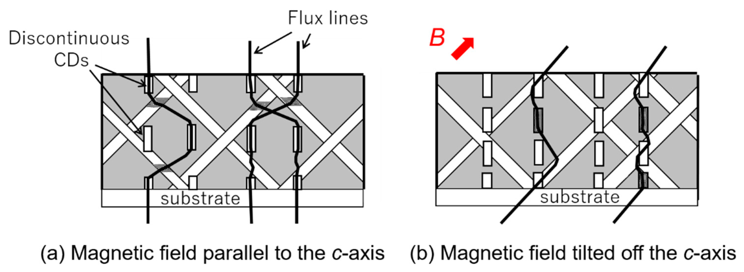
Swift-heavy-ion irradiation to high-Tc superconductors produces amorphous CDs of damaged material parallel to the projectile direction through the electron excitation process rather than the nuclear collision process. The CDs produced by the irradiation effectively work as one-dimensional PCs [13,14,15]. The orientation of one-dimensional PCs determines the preferential direction of flux pinning [13,16]. Therefore, heavy-ion irradiation can be expected to modify the anisotropy of Jc in high-Tc superconductors by tuning the irradiation direction. In addition, the size and shape of CDs strongly depends on the electronic stopping power Se, which is defined as energy loss of the incident ion per unit length via electronic excitation in the target material [17]: continuous CDs with thick diameter are formed at higher Se than a certain value and discontinuous CDs with thin diameter are located at intervals along the ion path at lower Se [18,19,20]. In particular, discontinuous CDs may provide more effective flux pinning in a wide magnetic field angular range, because the ends of discontinuous CDs can act as PCs even in magnetic field directions tilted from their long axis [21,22]. Thus, the discontinuity of CDs is also one of the important factors for the modification of the Jc anisotropy in high-Tc superconductors, as well as the direction-dispersion of CDs.
A major advantage of using heavy-ion irradiation for the formation of CDs is that any CD configuration can be prepared by tuning the irradiation energy and the incident direction [23,24], independently from a fabrication process of samples (see Figure 2): the pinning structure can be efficiently designed to meet the requirements for different applications, which would be valuable for the development of high-performance coated conductors. In addition, unique pinning structures architected by the irradiations may enable us to find new physics of flux line dynamics. Therefore, heavy-ion irradiation to high-Tc superconductors can provide the design criteria for the supreme pinning landscape making the most of the potential for flux pinning, which leads to Jc close to the theoretical limit of critical current density, i.e., the pair-breaking critical current density.
In this paper, we describe the results of the modification of the Jc properties in REBCO thin films and coated conductors, which were obtained by our studies through heavy-ion irradiation under various irradiation conditions. Most of previous works of other researchers using heavy-ion irradiation have focused on the improvement of Jc at B || c where Jc usually shows the minimum [13,14,15,18,19]. On the other hand, heavy-ion irradiation effects over a wide magnetic field angular range have not been well studied so far. By contrast, we focus especially on modification of the Jc anisotropy in high-Tc superconductors by using heavy-ion irradiation: our aim in this review is to improve Jc in all magnetic field angular range from B || c to B || ab by using CDs and to explore breakthroughs for strong and isotropic pinning landscape in REBCO coated conductors. To meet the aim in this paper, we selected Xe ions as the irradiation ion species: the Xe-ion irradiation to REBCO thin films can provide large increase of Jc without heavily damaging crystallinity even at a large amount of doses, 5.0 × 10¹¹ ions/cm2 [24] and easily enables us to tune the morphology of CDs through the adjustment of the irradiation energy at a tandem accelerator of Japan Atomic Energy Agency (JAEA) used in our works. Firstly, we present the reduction of the Jc anisotropy by using the direction-dispersed CDs, which are introduced by controlling the irradiation direction. Secondly, we report the influence of CDs tilted at small angle(s) relative to the ab-plane on the Jc properties near B || ab, which is one of key factors to improve Jc in all magnetic field directions. In particular, we show the influence of CDs along the ab-plane on Jc at B || ab by preparing an in-plane aligned a-axis-oriented YBCO film. Finally, we clarify the potential of discontinuous CDs for flux pinning in comparison with continuous CDs, where the morphology of CDs is controlled by the irradiation energy.
2. Experimental
The samples used in our works were mostly c-axis oriented YBCO thin films and GdBCO coated conductors. The c-axis oriented YBCO thin films were fabricated by a pulsed laser deposition (PLD) technique on (100) surface of SrTiO3 single crystal substrates. The thickness of the films was about 300 nm. The GdBCO coated conductor, on the other hand, was fabricated on an ion-beam-assisted deposition (IBAD) substrate by a PLD method (Fujikura Ltd., Tokyo, Japan). The thickness of GdBCO layer is 2.2 µm and the self-field critical current Ic of this tape with 5 mm width is about 280 A. The samples were cut from the tape of the GdBCO coated conductor. The Ag stabilizer layer on the superconducting layer was removed by a chemical process. The YBCO thin films and the samples cut from the GdBCO coated conductor were patterned into a shape of about 40 µm wide and 1 mm long micro-bridge before the irradiation.
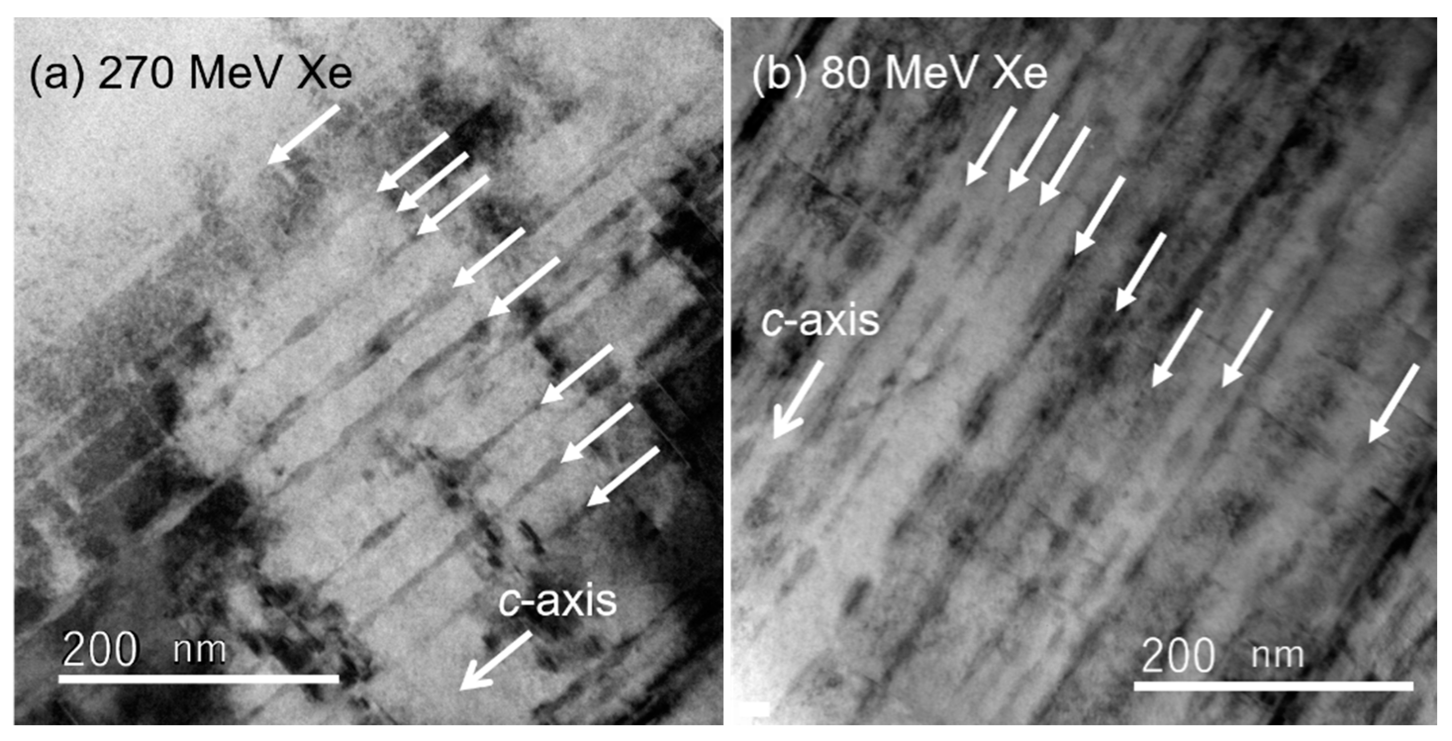
The heavy-ion irradiations with Xe ions were performed using the tandem accelerator of JAEA in Tokai, Japan. Tuning of the discontinuity of CDs along the c-axis can be controlled by the irradiation energy. The values of Se for the Xe-ion irradiation energies above 200 MeV are above 2.9 keV/Å, which is above the threshold value of Se = 20 keV/nm to create continuous CDs along the c-axis over the whole sample thickness for YBCO [17]. Thus, the irradiation with 200 MeV Xe ions was performed to install continuous CDs into YBCO thin films. In addition, the Xe-ion irradiation with 270 MeV was applied in order to create continuous CDs for GdBCO coated conductors, where the projectile length was longer than the thickness of 2.2 µm. Discontinuous CDs, on the other hand, were formed into YBCO thin films and GdBCO coated conductors by the irradiation with 80 MeV Xe ions, where the value of Se is below 20 keV/nm: the radius of CDs strongly fluctuates along the ion path and CDs are shortly segmented at intervals in their longitudinal direction when the Se is lower than the threshold value, as shown in Figure 3 [19,20,25]. All of the irradiation energies used in our works are enough for the projectile ranges to exceed the thickness of the samples: the incident ions pass through the superconducting layer completely.
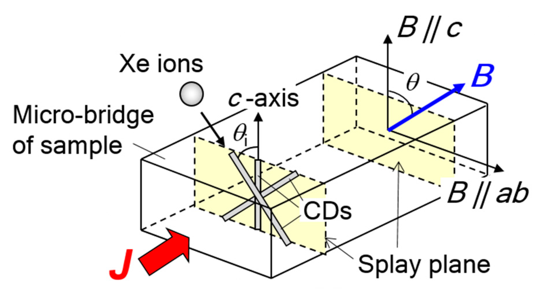
The direction of CDs was adjusted by controlling the incident ion beam direction tilted off the c-axis by θi, which was always directed perpendicular to the bridge direction of the sample (see Figure 4). When the irradiation directions are dispersed, the fluence in each irradiation direction is calculated by dividing the total fluence by the number of the irradiation directions. The fluence of the irradiation is often represented as a matching field Bφ: Bφ is the magnetic field where the density of flux lines is equal to that of CDs, e.g., the fluence of 4.84 × 10¹⁰ ions/cm2 corresponds to Bφ = 1 T.
It should be noted that the introduction of irradiation defects causes a lattice distortion of the host matrix, which affects the superconducting properties such as critical temperature (Tc). The strain induces the oxygen vacancies [26], resulting in the reduction of Tc: the value of Tc decreases when the fluence of the irradiation increases [24]. The strain also affects the Jc properties through the influence on Tc: Jc decreases largely, when the influence of the strain increases excessively. Therefore, the irradiation fluences were adjusted to avoid heavy damage to the crystallinity in our works.
The cross sections of the irradiated samples were observed by conventional transmission electron microscopy (TEM) with a JEM-2000 EX instrument (JEOL, Tokyo, Japan) operating at 200 kV. The thin TEM specimens were prepared by a focused ion beam method using an Quanta 3D system (FEI, Hillsboro, Oregon, USA). The Jc properties were measured through the transport properties by using a four-probe method. The Jc was defined by a criterion of electric field, 1 μV/cm. The transport current was always perpendicular to the magnetic field and the c-axis (maximum Lorentz force configuration). The magnetic field angular dependences of Jc were evaluated as a function of the angle θ between the magnetic field and the c-axis of the samples (see Figure 4).
3. Results and Discussion
3.1. Modification of Jc Around B || c by Controlling Heavy-Ion Irradiation Angles
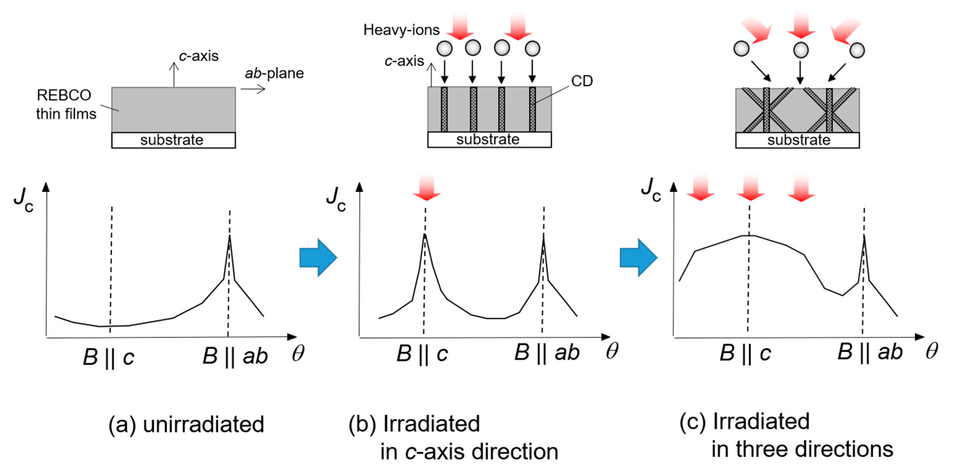
Heavy-ion irradiation can introduce CDs in any direction in a controlled manner, so we can install CDs at the magnetic field angles where the Jc shows a minimum, one by one: the material processing with heavy-ions is one of effective ways to modify the Jc anisotropy in high-Tc superconductors, which enables us to push up overall Jc, as shown in Figure 5.
We first examined the influence of bimodal angular distribution of CDs consisting of CDs crossing at ±θi relative to the c-axis on the Jc properties in a wide magnetic field angular range [27,28]. Figure 6 shows the magnetic-field angular dependence of Jc normalized by the self-magnetic-field critical current density Jc0 for YBCO thin films with the crossed CDs, which were installed by 200 MeV Xe ion irradiation with Bφ = 2 T (c10-2: θi = ±10°, c25-2: θi = ±25°, c45-2: θi = ±45°, p06-2: parallel CD configuration of θi = 6°, and Pure: unirradiated samples). The magnetic field was rotated in the splay plane where the two parallel CD families are crossing each other, as shown in Figure 4. All the irradiated samples show an additional peak of the normalized Jc around B || c (θ = 0°) for lower magnetic fields: the values of the normalized Jc are enhanced around B || c compared to the unirradiated one. This indicates that CDs with any crossing angle work as effective PCs, pushing up the Jc around B || c. The influence of the crossing angle of CDs is evident in the shape of the additional peak around B || c: the width of the normalized Jc peak becomes broader when the crossing angle is larger. Therefore, the bimodal angular distribution of CDs can expand the magnetic field angular range where the normalized Jc increases, by controlling the crossing angle.
It is noteworthy that the crossover phenomenon from the broad-plateau-like behavior to the double peak emerges on the normalized Jc around B || c for c45-2 when the magnetic field increases across the matching field of Bφ = 2 T: the normalized Jc more rapidly reduces at B || c with increasing magnetic field, which results in a dip structure at B || c for c45-2 at 2 T, as shown in Figure 6. In general, the Jc peak in the magnetic field angular dependence of Jc is a sign of long-axis correlated flux pinning of CDs. Their-long-axis correlated flux pinning is maintained up to higher magnetic fields [29,30]. For the crossing angle of θi = ±45°, by contrast, the influence of the long-axis correlated flux pinning is weakened at B || c, since the directions of CDs are far from the c-axis direction. Thus, the dip behavior at B || c is a sign of disappearance of their-long axis correlated flux pinning at B || c.
The effective magnetic field angular region for flux pinning of CDs is described by a trapping angle φt, at which flux lines begin to be partially trapped by CDs [4]. The general formula of φt is expressed as:
where εp is the pinning energy of CDs and εl is the line tension of flux lines. The line tension energy of flux lines in anisotropic superconductors is given by the following equation:
where Θ is the angle between the magnetic field and the ab-plane, ε0 is a basic energy scale, γ is the mass anisotropy, and ε(Θ) = (sin2Θ + γ −2 cos2Θ)1/2 [4]. The trapping angle φt is experimentally estimated as the difference in the angle between the peak value and the minimum one on the magnetic field angular dependence of Jc [31]. For p06-2, the value of φt is ~55° at B < Bφ, which is estimated from Figure 6a. Using this value of φt as the trapping angle of CDs parallel to the c-axis approximately and γ = 5 together with equations (1) and (2), the value of φt for CDs tilted at θi = 45° is about 37°. Therefore, CDs tilted at θi = 45° hardly contribute to trapping flux lines at B || c: CDs tilted at θi = 45° does not work as their-long-axis correlated PCs for B || c.
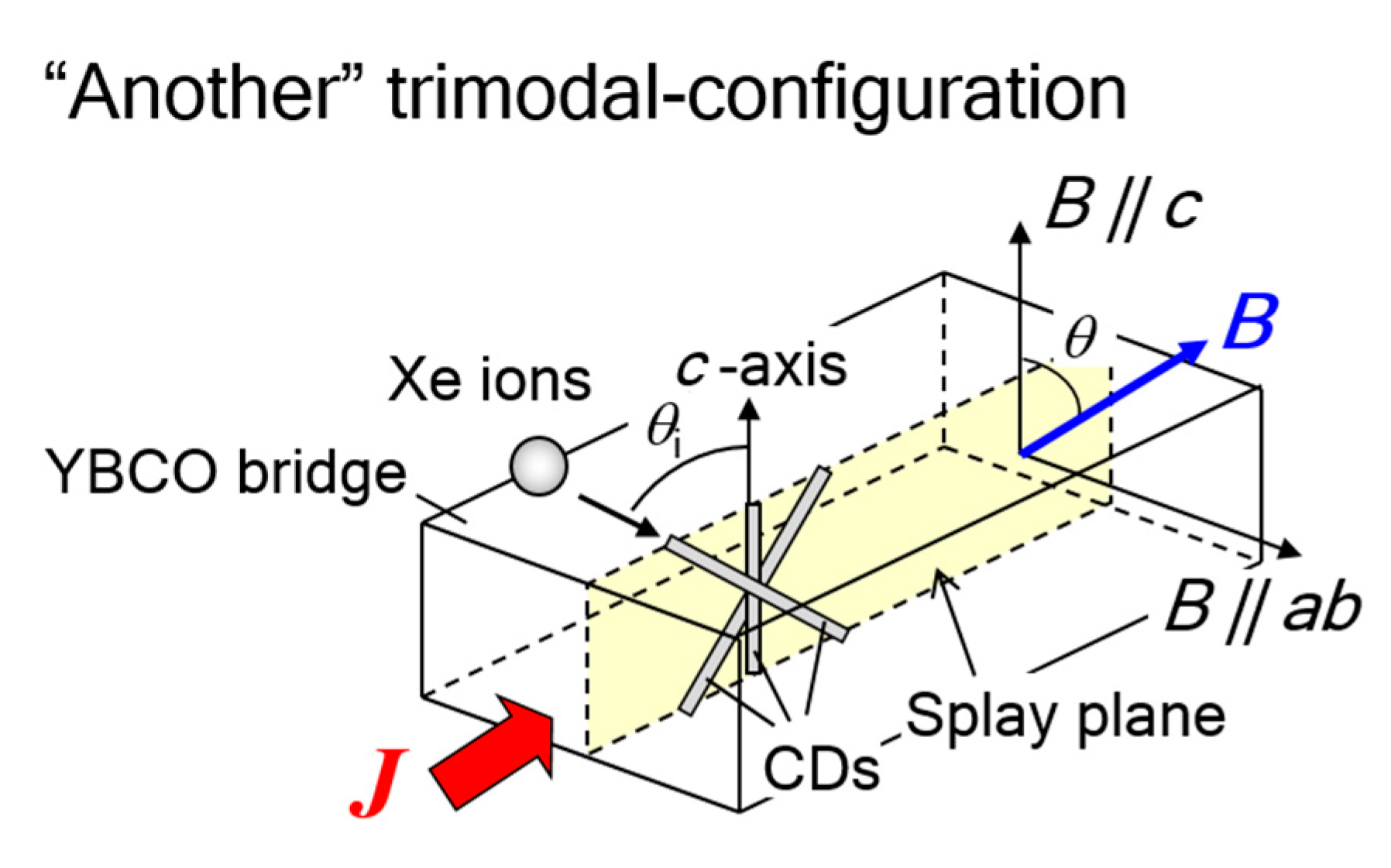
The bimodal angular distribution of CDs for θi ±45° gives rise to the drop in Jc at the mid-direction of the crossing angle. Secondly, we investigated the flux pinning properties for a trimodal angular distribution of CDs consisting of CDs crossing at θi = 0° and ±45° (referred to as the “standard” trimodal-configuration), in order to obtain high Jc with no drop over a wide magnetic field angular region [32]. In addition, another geometry for the trimodal configuration was prepared, where a splay plane defined by the three irradiation angles is parallel to the transport current direction (referred to as “another” trimodal-configuration), as shown in Figure 7: the two trimodal configurations enable us to elucidate the influence of the splay plane direction on the Jc properties directly. Figure 8 shows the magnetic field angular dependence of normalized Jc by Jc0 (= jc) at several magnetic fields from 1 T up to 5 T for YBCO thin films with the trimodal angular configurations of CDs. A large enhancement of jc centered at B || c can be seen for all the irradiated samples. In particular, both the trimodal angular configurations show a much broader peak with larger jc than that of the parallel CD configuration. It should be noted that there is no drop of jc at B || c for both the trimodal configurations. This result indicates that the three parallel CD families tilted at θi = 0° and ±45° effectively work as strong PCs in each irradiation direction: flux pinning at B || c where CDs tilted at θi = ±45° slightly contribute to trapping flux lines, is reinforced by CDs along the c-axis.
Interestingly, the behaviour of jc around B || c strongly depends on the direction of the splay plane for the trimodal configuration of CDs: the jc of another trimodal-configuration shows a peak at B || c, whereas standard one exhibits not so much a peak as a plateau-shaped curve. In addition, the height of jc peak for another tirmodal-configuration is higher than the value of jc at B || c for standard one. For standard trimodal-configuration, sliding motion of flux lines occurs along the tilted CDs at B || c because of the splay plane parallel to the Lorentz force, resulting in the reduction of the pinning efficiency [33]. The crossed CDs for another trimodal-configuration, by contrast, suppress the motion of flux lines efficiently, since flux lines move across the crossed CDs by the Lorentz force. Thus, the splay plane parallel to the transport current direction provides stronger flux pinning at B || c, like planar PCs. Furthermore, the jc of another trimodal-configuration is the highest even when the magnetic field is tilted from the c-axis. This is probably due to the entanglement of flux lines induced in a mesh of the splay plane tilted from the magnetic field, where the motion of flux lines is suppressed [34]. These results suggest that the direction of the splay plane is one of key factors for flux pinning of direction-dispersed CDs, as well as the degree of the direction-dispersion [32,35].
3.2. Modification of Jc Anisotropy by Controlling Number of Heavy-Ion Irradiation Directions
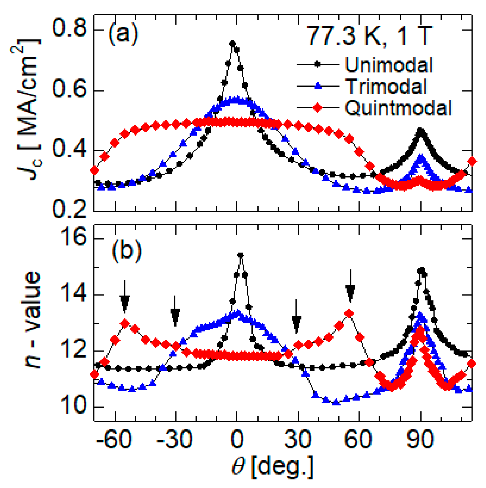
We further increased the number of the directions of CDs by controlling the irradiation directions (see Figure 9), in order to spread the strong pinning effect of CDs over a wider magnetic field angular range. Figure 10 shows the magnetic field angular dependence of Jc and n-values for YBCO thin films with direction-dispersed CDs, where the number of directions of CDs was applied from one to five every 30 degrees [36]. The n-value is estimated from a linear fit to empirical formula of electric field (E) versus current density (J), E ~ J n in the range of 1 to 10 μV/cm. The n-value is equivalent to U0 / kBT (U0: pinning potential energy) [37,38], representing thermal activation for flux motion. When the number of CD directions is increased, the angular region with high Jc is more expanded. Note that the height of the Jc peak at B || c declines, since the density of CDs decreases with increasing number of irradiation directions in this work. Thus, the large direction-dispersion of CDs is effective for the enhancement of Jc over a wider magnetic field angular region centered at B || c.
The Jc around B || ab, on the other hand, does not seems to be affected by flux pinning of the direction-dispersed CDs: both Jc and n-value at θ = 90° rather tend to decrease with increasing the degree of the direction-dispersion of CDs. One of the reasons for the reduction of Jc at B || ab by the introduction of CDs is the damage on the superconductivity and/or the ab-plane-correlated PCs [16]. It should be noted that the sample of Quintmodal contains CDs crossing at ±30° relative to the ab-plane (i.e., θi = ±60°); nevertheless, the crossed CDs do not seem to contribute to the pinning interaction around B || ab. Figure 11 represents the magnetic field angular dependence of Jc for YBCO thin films including bimodal angular configurations of CDs with θi = ±30° and ±60° relative to the c-axis, respectively [39]. The crossing angle of ±30° relative to the c-axis induces the enhancement of Jc over a wide angular region centered at B || c. The crossing of CDs at ±30° relative to the ab plane, i.e., θi = ±60°, by contrast, is ineffective in pushing up the Jc at the mid-direction of the crossing angle, i.e., at B || ab, whereas the peak of Jc emerges at θ = ±60°. These results indicate that the flux pinning around B || ab is hardly affected even by CDs tilted toward the ab-plane, which significantly differs from the flux pinning of CDs at B || c. Thus, the flux pinning of CDs around B || ab is a new issue for the complete reduction of the Jc anisotropy.
3.3. Modification of Jc Around B || ab by Controlling Heavy-Ion Irradiation Directions
A significant enhancement of Jc at B || c has been caused by the introduction of artificially PCs, which is much higher than Jc at B || ab now [40]. Thus, the improvement of Jc at B || ab has been required at the next step, in order to increase overall Jc. The influence of CDs on the flux pinning at B || ab, however, has not been well studied so far, because the Jc at B || ab is the highest innately due to the electronic mass anisotropy in high-Tc superconductors [4] and the introduction of CDs is generally difficult in the direction close to the ab-plane. In contrast, heavy-ion irradiation can be an effective tool even for exploring the flux pinning effect of CDs at B || ab, because CDs can be installed in any direction by adjusting the irradiation direction.
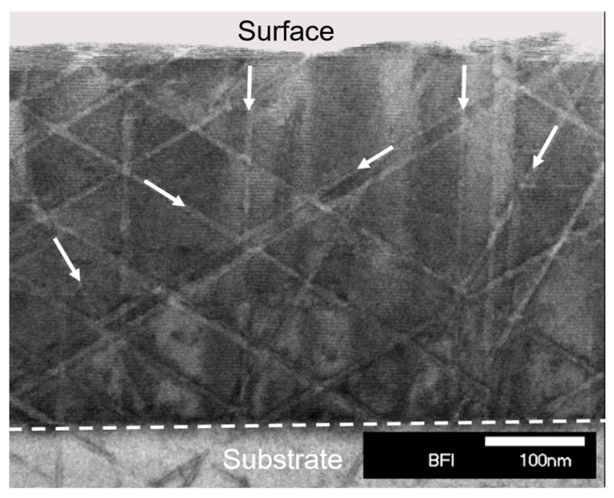
GdBCO-coated conductors were irradiated with 270 MeV Xe-ions, where the irradiation angle Θi relative to the ab-plane was controlled in the range from ±5° to ±15° relative to the ab-plane in order to install crossed CDs around the ab-plane [41]. The cross-sectional TEM image of the GdBCO-coated conductor irradiated at Θi = ±10°, Figure 12, shows the formation of continuous CDs along the irradiation directions. At the bottom part of the GdBCO layer, by contrast, some CDs become thinner and indicate angular dispersion in the irradiation directions. This is due to smaller value of Se than the threshold value of 20 keV/nm for the formation of continuous CDs [17,42], because the Se changes from 29.1 to 7.40 keV/nm through the GdBCO layer for the oblique irradiation at Θi = 10°.
Figure 13 shows the magnetic field angular dependence of Jc for the irradiated samples with Θi = ±5°, ±10°, and ±15°, respectively. The CD crossing-angles of Θi ≤ ±15° significantly affect the magnetic field angular variation of Jc around B || ab. The introduction of crossed CD at Θi = ±15° provides a triple peak of Jc centered at B || ab, where a large Jc peak exists at B || ab and the other two Jc peaks emerge around θ = 75° and 105°, independently each other. This behavior is in contrast to the case of CDs crossing at θi ≤ ±30° relative to the c-axis, which shows a single peak of Jc centered at B || c, as represented in Figure 6 and Figure 11. As the crossing-angle of Θi decreases, the two divided peaks of Jc at ±Θi overlap with the central Jc peak at B || ab: a single peak centered at θ = 90° occurs for the crossing angles of Θi ≤ ±10°. In particular, the crossing angle of Θi = ±5° provides the large and sharp Jc peak at B || ab, showing the highest value of all the samples at B || ab. To our knowledge, it is the first confirmation that CDs contribute to the improvement of Jc at B || ab.
These behaviors are closely associated with the elastic properties of flux lines around B || ab. The line tension energy of flux lines becomes very strong at B || ab, where the core of flux lines shows the elliptical nature in anisotropic superconductors. The strong line tension of flux lines significantly affects the trapping angle φt of CDs tilted toward the ab-plane. In general, the value of φt for CDs along the c-axis (i.e., at Θi = 90°) is about 65° in GdBCO coated conductors [25]. The φt for CDs tilted at small angle of Θi, on the other hand, can be evaluated by substituting the value of φt ~ 65° for Θi = 90° and γ = 5 together with equations (1) and (2): φt ~ 6.6° for Θi = 5°, φt ~ 8.7° for Θi = 10°, and φt ~ 11.9° for Θi = 15°. Thus, the trapping angles of CDs tilted toward the ab-plane becomes very small: flux lines are hardly trapped along CDs when the magnetic field direction is displaced from the direction of CDs even slightly. In particular, the trapping angle for CDs tilted at Θi ≥ 10° is smaller than the CD tilt-angle Θi, suggesting that the tilted CDs hardly affect the flux pinning at B || ab. Therefore, CDs tilted at Θi ≥ 10° and the ab-plane correlated PCs provide flux pinning independently. The CDs tilted at Θi = 5°, on the other hand, can fully contribute to the improvement of Jc at B || ab, because the trapping angle exceeds the value of Θi.
3.4. Modification of Jc at B || ab by Heavy-Ion Irradiation along the a-Axis
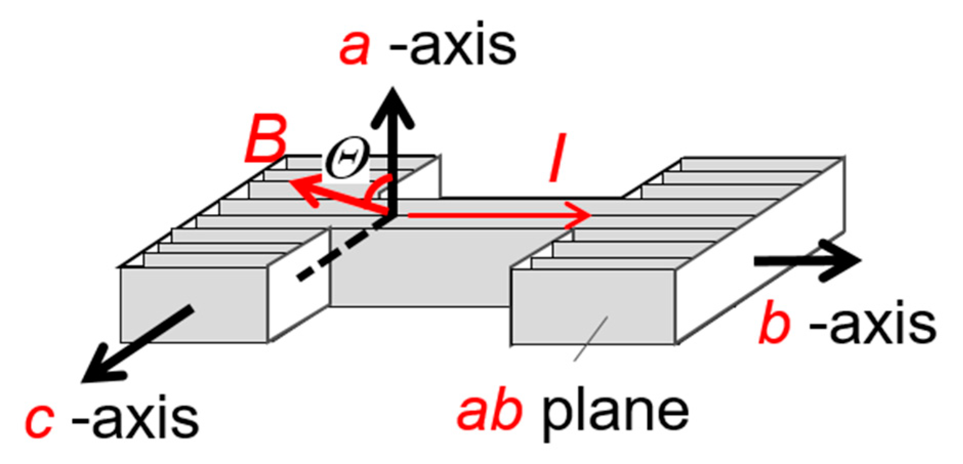
An in-plane aligned a-axis-oriented YBCO film offers an excellent opportunity for further exploration into the influence of CDs on the flux pinning at B || ab, since we can easily install CDs along the ab-plane with the ion-beam normal to the film [43]. We prepared the in-plane aligned a-axis-oriented YBCO film by a PLD technique with an ArF excimer laser, where a (100) SrLaGaO4 substrate with Gd2CuO4 buffer layer was used to promote the in-plane orientation of YBCO thin film [44]. The film was patterned into the shape of a microbridge so as to make the bridge direction parallel to the b-axis, where transport current can be applied along the ab-plane (see Figure 14). Both the in-plane-aligned texture of the film and the experimental arrangement enable us to remove the extra effect such as the interlayer Josephson current and the channel flow of flux lines along the CuO2 plane, providing deeper insights on the nature of flux pinning of CDs along the ab-plane.
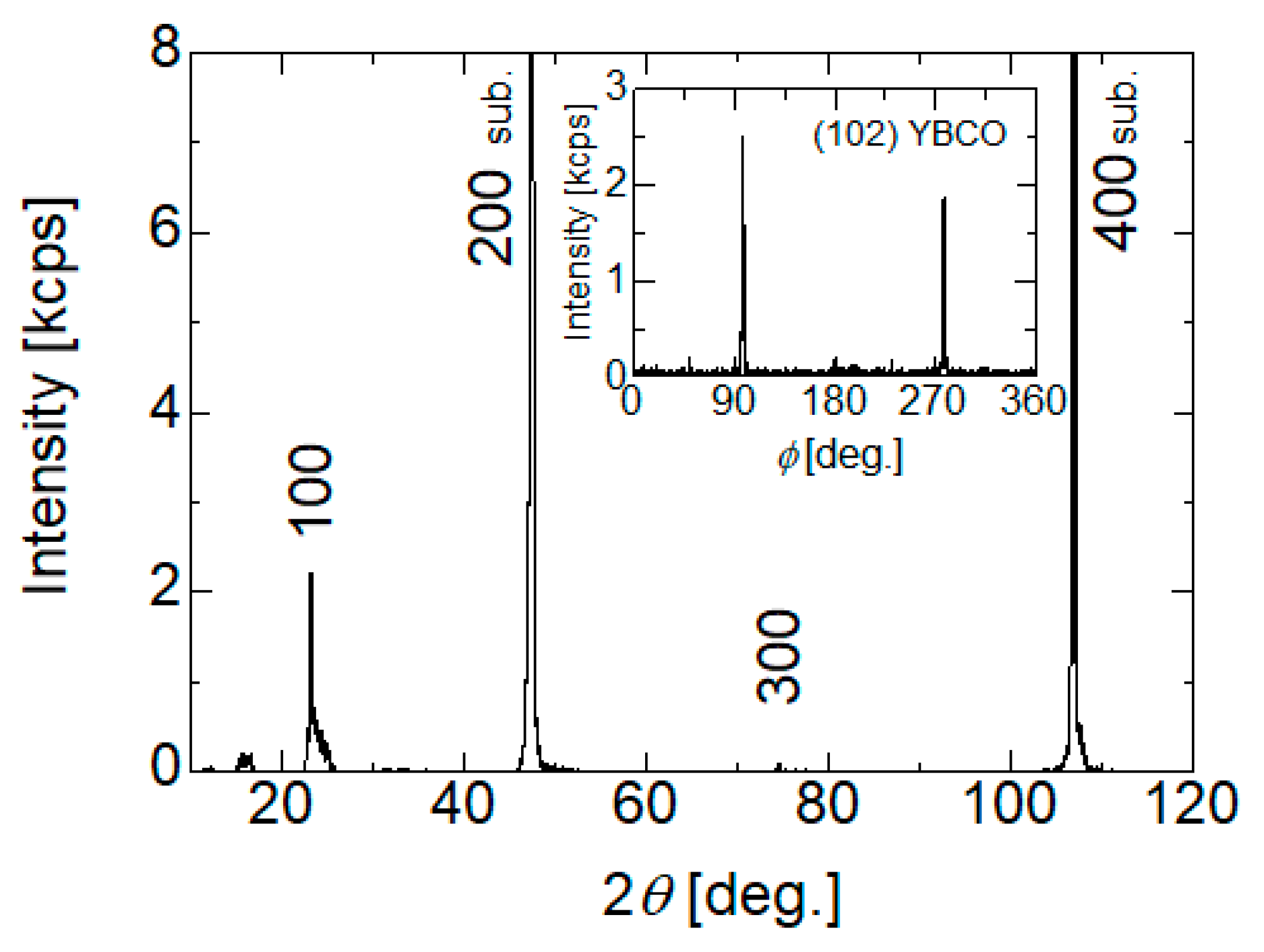
The in-plane aligned a-axis-oriented YBCO thin film showed good a-axis orientations without other orientations for the X-ray θ-2θ diffraction pattern, as shown in Figure 15. In addition, X-ray diffraction φ scanning using the (102) plane of the YBCO film before the irradiation indicated two-fold symmetry, since strong peaks stood out at around 90° and 270° in the inset of Figure 15. Therefore, the in-plane aligned a-axis-orientated microstructure can be confirmed on the film used in this work.
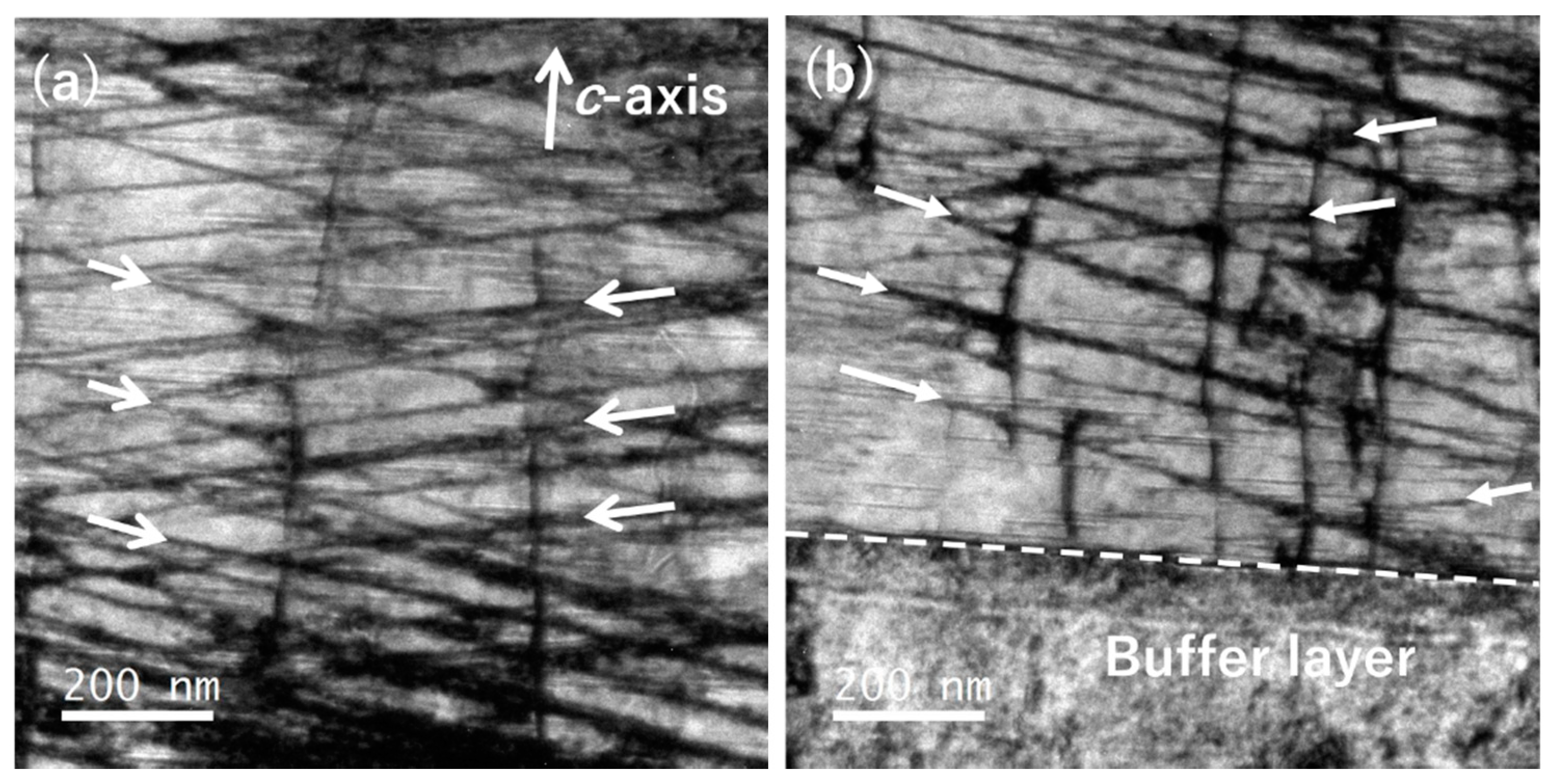
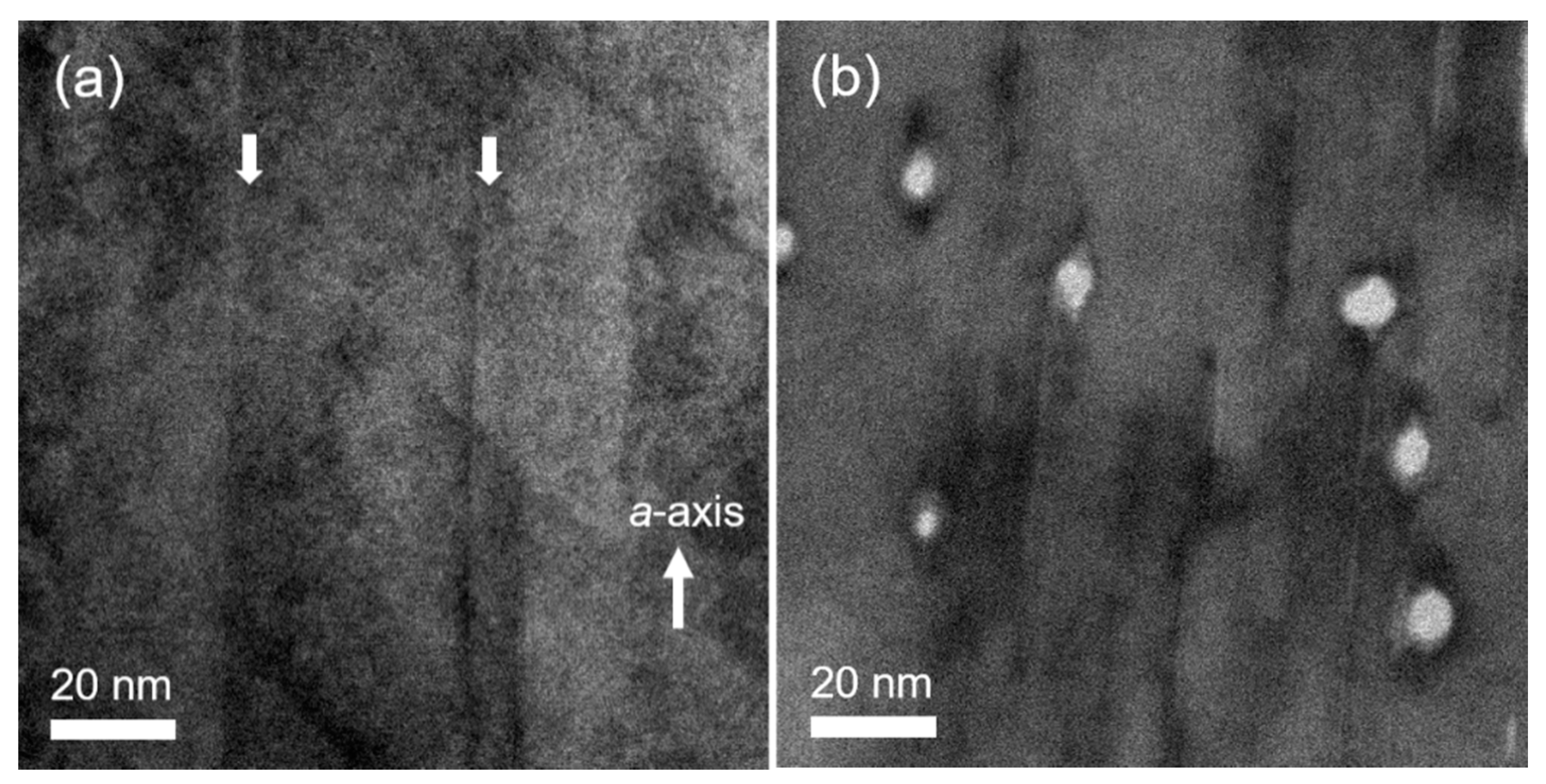
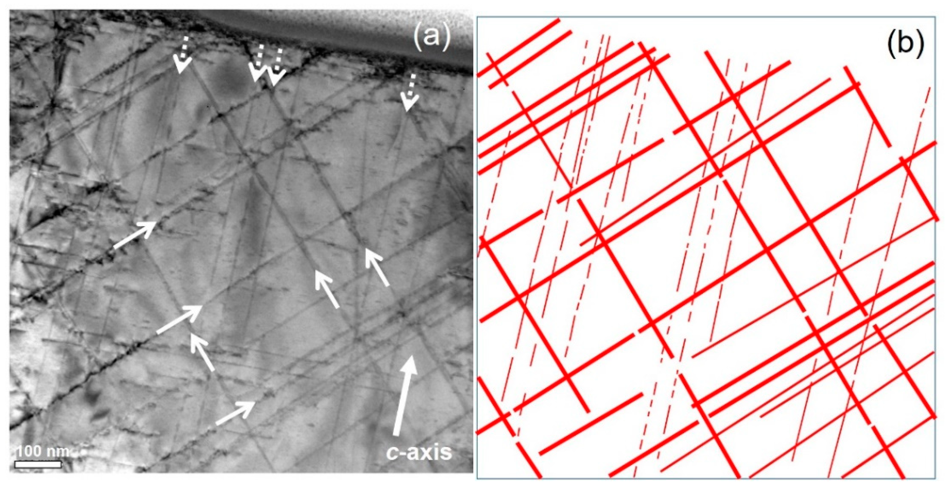
A cross-sectional TEM image of the in-plane aligned a-axis oriented YBCO film after the irradiation with 200 MeV Xe ions is shown in Figure 16a. The straight CDs along the a-axis are elongated through the thickness of the YBCO film. Figure 16b shows the plan-view TEM image of the a-axis oriented YBCO thin film after the irradiation. The CDs formed by the ion beam along the a-axis are roughly elliptical in shape, whereas CDs parallel to the c-axis are usually circular [17,45]. In general, the shape of CDs depends on the direction of the incident ions relative to the crystallographic axes in high-Tc superconductors, because the anisotropy of thermal diffusivity causes more severe irradiation damage for the creation of CDs along the a- and/or the b-axis [17].
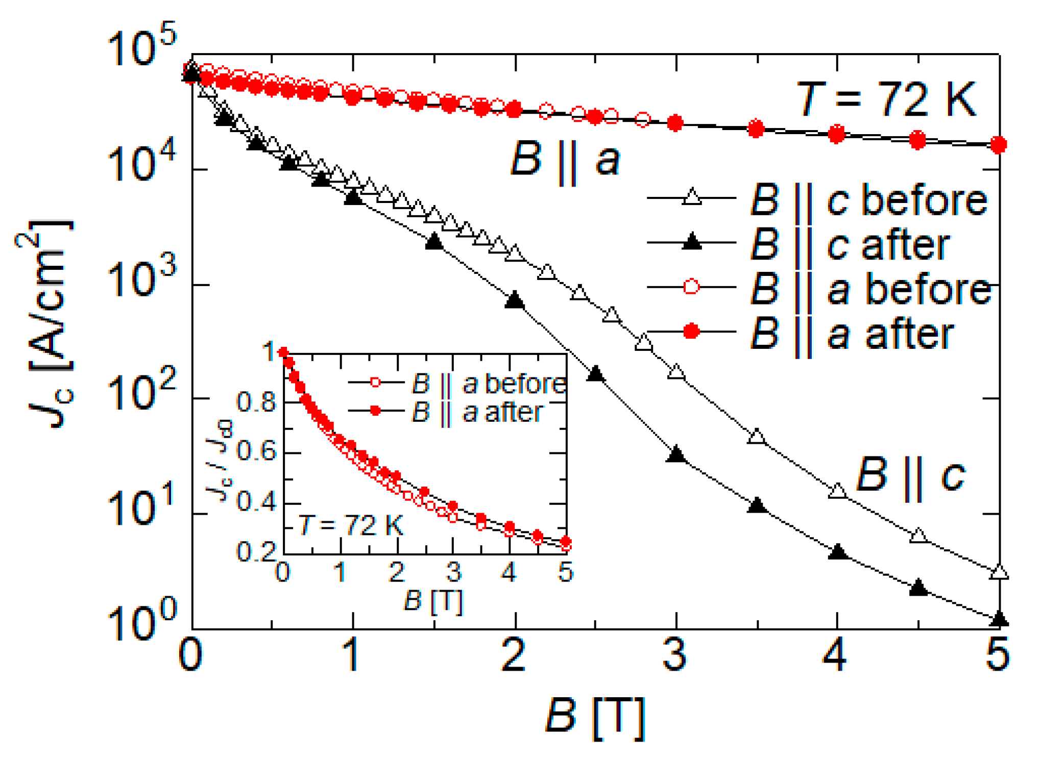
Figure 17 represents the magnetic field dependence of Jc at 72 K for the a-axis oriented YBCO film before and after the irradiation. The Jc at B || c is reduced by the introduction of CDs along the a-axis, especially for high magnetic fields. The CDs along the a-axis hardly interact with flux lines at B || c, since the CDs are perpendicular to the magnetic field direction. Moreover, CDs perpendicular to magnetic field direction create easy channel for flux lines to creep along the length of the CDs [46]. In addition to these deterioration effects, the irradiation damage to the host matrix causes the pronounced reduction of Jc at B || c.
The introduction of CDs along the a-axis, on the other hand, hardly reduces the absolute value of Jc at B || a, even though the Jc is affected by the local irradiation damage to the CuO2 planes as well as the Jc at B || c. It should be noted that the normalized Jc by Jc0 increases after the irradiation, especially for high magnetic fields (see the inset of Figure 17). This behavior suggests that CDs contribute to the flux pinning at B || ab. For low magnetic fields, by contrast, the pinning effect of CDs along the a-axis is hardly visible even on the normalized Jc. This is attributed to the presence of the naturally growth defects such as stacking faults in the film: Such pre-existing defects act as ab-plane correlated PCs both before and after the irradiation, which obscures the pinning effect of CDs, especially for low magnetic fields.
3.5. Modification of the Jc Anisotropy by Controlling the Heavy-Ion Irradiation Energy
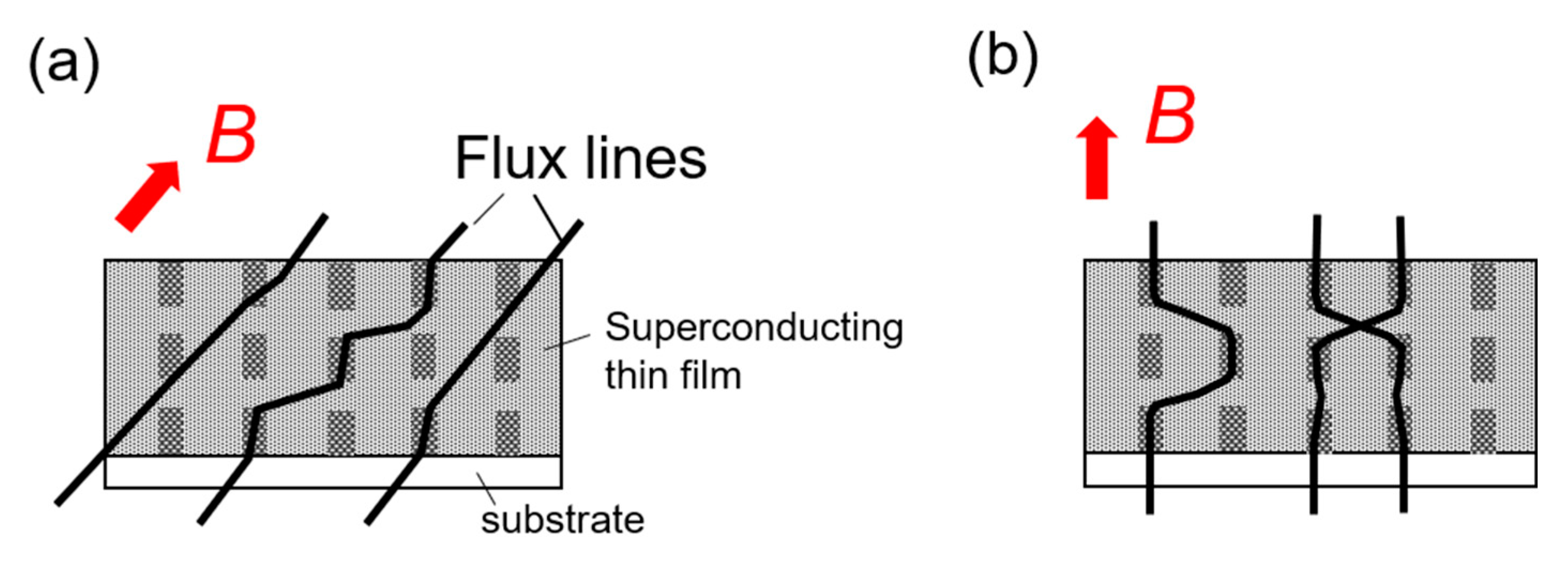
The modification of the Jc anisotropy in high-Tc superconductors is sensitive to direction-dispersions of CDs, as mentioned in the previous sections. Another way to modify the Jc properties by CDs is to tune the morphologies of CDs. Especially for the morphology of short segmented (i.e., discontinuous) CDs, the ends of the discontinuous CDs can provide a variety of additional pinning effects: the ends of the segmented CDs can trap flux lines in magnetic field tilted from their long axis [21,22] and the existence of gaps in the segmented CDs can suppress thermal motion of flux lines, as shown in Figure 18. Furthermore, the volume fraction of CDs relative to the superconducting area can be minimized for discontinuous CDs, since CDs are shortly segmented: the reduction of the volume fraction of the crystalline defects suppresses the degradation of the superconductivity associated with the introduction of PCs, leading to the improvement of the absolute value of Jc in a whole magnetic field angular region [19,20]. For iron-based superconductors, the morphology of CDs formed by heavy-ion irradiation tends to be discontinuous, which induces the remarkable improvement of Jc [47,48,49]. The morphology of CDs in high-Tc superconductors can be tuned by adjusting the irradiation energy for heavy-ion irradiation. In addition, the pinning effect of discontinuous CDs can be compared directly with that of continuous ones under same irradiation conditions except for the irradiation energy: the heavy-ion irradiations with different irradiation energies enable us to clarify the superiority of discontinuous CDs in the flux pinning effect over continuous CDs.
We first compared the flux pinning properties of discontinuous CDs with those of continuous ones when their long axis is parallel to the c-axis: GdBCO-coated conductors were irradiated with 80 MeV and 270 MeV Xe-ions along the c-axis, respectively [25]. For the irradiated sample with 270 MeV Xe ions, the straight and continuous CDs with the diameter of 4-11 nm penetrate the superconducting layer along the c-axis, as shown in Figure 3a. The value of Se calculated using SRIM code varies from 3.0 to 2.8 keV/Å through the superconducting layer with the thickness of 2.2 μm for the 270 MeV Xe-ion irradiation, so that the continuous CDs are formed over the whole sample. The 80 MeV Xe-ion irradiation, by contrast, produces short segmented CDs in their longitudinal direction along the c-axis, as shown in Figure 3b: the length of the segmented CDs with the diameter of 5-10 nm varies from 15 to 50 nm along their length, while the gaps between the segmented CDs is also variable, ranging between 15 and35 nm. The formation of discontinuous CDs is attributed to the value of Se changing from 2.0 to 1.4 keV/Å for the 80 MeV Xe ions into REBCO thin films [17,19,20].
Figure 19 shows the magnetic field angular dependences of Jc at 70 K and 84 K in GdBCO-coated conductors irradiated with 80 MeV and 270 MeV Xe ions, respectively. The 80 MeV irradiation causes higher Jc in all magnetic field directions compared to the 270 MeV irradiation, which becomes more pronounced at lower temperature of 70 K. The high Jc at B || c for the 80 MeV irradiation is attributed to the existence of gaps in the segmented CDs, which induce the suppression of thermal motion of flux lines (see Figure 18b). In addition, the ends of discontinuous CDs can trap flux lines in magnetic field tilted from their long axis, as shown in Figure 18a. These flux pinning effects of discontinuous CDs become more remarkable at lower temperature where a core size of flux line approaches the thin diameter of the discontinuous CDs. Moreover, discontinuous CDs more minimize the degradation of the superconductivity associated with the introduction of PCs compared with continuous CDs. Thus, the discontinuity of CDs can contribute to further enhancement of Jc.
The superior flux pinning effect of discontinuous CDs can be further modified by tuning the direction-dispersion. We irradiated GdBCO coated conductors with 80 MeV Xe ions, where the incident ion beams were tilted from the c-axis by θi to introduce various kinds of direction-dispersed CDs: a parallel configuration composed of CDs parallel to the c-axis, bimodal angular configuration composed of CDs tilted at θi = ±45° relative to the c-axis, and trimodal angular configuration composed of CDs tilted at θi = 0° and ±45° [50].
Figure 20a shows a cross-sectional TEM image of the GdBaCuO-coated conductor irradiated with 80 MeV Xe-ions at θi = 0° and ±45°. The morphologies of CDs are schematically emphasized in Figure 20b. Interestingly, the 80 Me V Xe-ion beams create CDs with different morphologies depending on the irradiation angles of θi: thick and elongated CDs are formed along the ion path at θi = 45°, whereas the 80 MeV ions at θi = 0° creates short segmented CDs along their length. In general, the morphology of CDs is determined by the value of Se, which is the energy transferred from the incident ions for the electronic excitation. A thermal spike model [51,52], which is one of models to interpret the formation of irradiation defects through the electronic excitation, can describes the direction-dependent morphologies of CDs in high-Tc superconductors by considering the anisotropy of thermal diffusivity [17,50]. According to the thermal spike model, the energy of the electronic excitation is converted into the thermal energy of lattice, which is the source for the formation of irradiation defects. In high-Tc superconductors, the thermal diffusivity along the c-axis is smaller than that along other crystallographic axes, which results in the suppression of a temperature spread in the planes containing the c-axis. Thus, the incident ion beam tilted from the c-axis causes more severe structural damage, resulting in the formation of elongated CDs with a thicker diameter.
Figure 21 shows the magnetic field angular dependence of Jc for GdBCO coated conductors irradiated with 80 MeV and 270 MeV Xe ions, where the irradiation angles are θi = 0° for the parallel CD configurations and θi = 0°, ±45° for the trimodal angular configuration, respectively. The trimodal angular distribution shows higher Jc values than the parallel CD configuration at 70 K under the same irradiation energy. This suggests that the direction-dispersion of CDs is more effective to enhance the flux pinning over a wide magnetic field angular region, as mentioned in Section 3.2. It is noteworthy that the trimodal angular configuration produced by 80 MeV Xe ions shows the highest Jc in all the CD configurations over the whole magnetic field angular region at 70 K. The 80 MeV trimodal configuration consists of short segmented CDs along the c-axis and elongated CDs crossing at θi= ±45°, as shown in Figure 20a. For B || c, the motion of double kinks of flux lines peculiar to one-dimensional PCs is suppressed by the gaps between the segmented CDs, as shown in Figure 18b. Furthermore, continuous CDs crossing at θi = ±45° assist in trapping the unpinned segments of flux lines, as shown in Figure 22a. The pinning of kinks of flux lines is effective for further improvement of Jc [53,54]. Therefore, the combination of discontinuous CDs and continuous ones crossing at θi = ±45° provides the enhancement of Jc at B || c.
At the intermediate angles between B || c and B || ab, on the other hand, the continuous CDs crossing at θi = ±45° predominantly trap flux lines. In addition, the flux pinning of CDs crossing at θi = ±45° is further enhanced through the suppression of the motion of kinks of flux lines by the gaps in discontinuous CDs, as shown in Figure 22b. Thus, the hybrid flux pinning by the two different kinds of PCs causes the large enhancement of Jc even at the intermediate magnetic field angles.
There is a possibility that direction-dispersed CDs with “complete discontinuity” further provide a high and isotropic Jc in high-Tc superconductors. In fact, BaHfO3. nano-rods tend to grow discontinuously and to be widely dispersed in the directions, causing a significant improvement of Jc in a wide magnetic field angular range for REBCO thin films [55,56]. The irradiation using lighter ions with lower energy, which provides lower Se for high-Tc superconductors (e.g., Kr-ion irradiation with 80 MeV, where Se = 16.0 keV/nm), may produce discontinuous CDs even in directions tilted from the c-axis. However, there is a trade-off between the discontinuity of CDs and the thickness of CDs for the formation of CDs by heavy-ion irradiations: discontinuous CDs tend to be thin diameter [18,25], where the elementary pinning force of one segmented column with thin diameter becomes weak. Thus, the discontinuity of CDs does not always provide the strong pinning landscape for the heavy-ion irradiation process. The introduction of direction-dispersed, discontinuous, and thick CDs by the ion irradiation process can be the key to further making high Jc fairly isotropic in high-Tc superconductors.
4. Conclusions
We have systematically examined the modification of the anisotropy of Jc in REBCO thin films by using heavy-ion irradiations: the morphology and the configuration of the irradiation defects were controlled by the irradiation conditions such as the irradiation energy and the incident direction. The direction-dispersed CDs were designed in REBCO thin films to push up the Jc in the magnetic field angular region from B || c to B || ab, by controlling the irradiation directions. When the directions of CDs were extensively dispersed around the c-axis, the Jc was enhanced over a wider magnetic field angular region centered at B || c. The Jc at B || ab, on the other hand, was hardly affected even by CDs tilted toward the ab-plane, which is attributed to the strong line tension energies of flux lines around B || ab in the anisotropic superconductors. We demonstrated the improvement of Jc at B || ab by the introduction of CDs, where the angle of CDs relative to the ab-plane were controlled down to Θi = 5°. These results suggest that direction-dispersed CDs can provide the isotropic enhancement of Jc over all magnetic field angular region when the angles of CDs are matched with the anisotropic line tension energy of flux lines.
Another promising morphology of CDs, i.e., discontinuous CDs, which can be introduced by heavy-ion irradiation with relatively low energy, showed large potential for the enhancement of Jc over a wide magnetic field angular region. In particular, the combination of the discontinuity and the direction-dispersion lead to further enhancement of Jc: the gaps in discontinuous CDs provide the suppression of the motion of flux lines, while the direction-dispersion of CDs produces the strong flux pinning over a wide magnetic field angular region.
The heavy-ion irradiation to high-Tc superconductors can provide the flux pinning structure with higher and more isotropic Jc, by further tuning the irradiation process: the systematic studies using the ion irradiation process may lead to the approach to the theoretical limit of Jc, i.e., pair-breaking critical current density.
Author Contributions
Conceptualization, T.S. All authors have read and agreed to the published version of the manuscript.
Funding
This work was supported by KAKENHI (25420292, 16K06269 and 19K04474) from the Japan Society for the Promotion of Society.
Data Availability Statement
The data presented in this study are available on request from the author.
Acknowledgments
The author thanks N. Ishikawa, M. Mukaida, A. Ichinose, K. Yasuda, T. Fujiyoshi, S. Semboshi, T. Ozaki, and H. Sakane for their constant support during the researches. Experimental works were partly performed under the Common-Use Facility Program of JAEA.
Conflicts of Interest
The authors declare no conflict of interest.
References
- Obradors, X.; Puig, T. Coated conductors for power applications: Materials challenges. Supercond. Sci. Technol. 2014, 27, 044003. [Google Scholar] [CrossRef]
- Shiohara, Y.; Yoshizumi, M.; Takagi, Y.; Izumi, T. Future prospects of high Tc superconductors-coated conductors and their applications. Physica C 2013, 484, 1–5. [Google Scholar] [CrossRef]
- Matsumoto, K.; Mele, P. Artificial pinning center technology to enhance vortex pinning in YBCO coated conductors. Supercond. Sci. Technol. 2010, 23, 014001. [Google Scholar] [CrossRef]
- Blatter, G.; Feigelman, M.V.; Geshkenbein, V.B.; Larkin, A.I.; Vinokur, V.M. Vortices in high-temperature superconductors. Rev. Mod. Phys. 1994, 66, 1125–1388. [Google Scholar] [CrossRef]
- Awaji, S.; Namba, M.; Watanabe, K.; Kai, H.; Mukaida, M.; Okayasu, S. Flux pinning properties of correlated pinning at low temperatures in ErBCO films with inclined columnar defects. J. Appl. Phys. 2012, 111, 013914. [Google Scholar] [CrossRef]
- Foltyn, S.R.; Civale, L.; MacManus-Driscoll, J.L.; Jia, Q.X.; Maiorov, B.; Wang, H.; Maley, M. Materials science challenges for high-temperature superconducting wire. Nat. Mater. 2007, 6, 631–642. [Google Scholar] [CrossRef] [PubMed]
- Feighan, J.P.F.; Kursumovic, A.; MacManus-Driscoll, J.L. Materials design for artificial pinning centers in superconductor PLD coated conductors. Supercond. Sci. Technol. 2017, 30, 123001. [Google Scholar] [CrossRef] [Green Version]
- MacManus-Driscoll, J.L.; Foltyn, S.R.; Jia, Q.X.; Wang, H.; Serquis, A.; Civale, L.; Maiorov, B.; Hawley, M.E.; Maley, M.P.; Peterson, D.E. Strongly enhanced current densities in superconducting coated conductors of YBa2Cu3O7−x+BaZrO3. Nat. Mater. 2004, 3, 439–443. [Google Scholar] [CrossRef]
- Gapud, A.A.; Kumar, D.; Viswanathan, S.K.; Cantoni, C.; Varela, M.; Abiade, J.; Pennycook, S.J.; Christen, D.K. Enhancement of flux pinning in YBa2Cu3O7 thin films embedded with epitaxially grown Y2O3 nanostructures using a multi-layering process. Supercond. Sci. Technol. 2005, 18, 1502–1505. [Google Scholar] [CrossRef]
- Mele, P.; Matsumoto, K.; Horide, T.; Ichinose, A.; Mukaida, M.; Yoshida, Y.; Horii, S.; Kita, R. Ultra-high flux pinning properties of BaMO3-doped YBa2Cu3O7-x thin films (M = Zr, Sn). Supercond. Sci. Technol. 2008, 21, 032002. [Google Scholar] [CrossRef]
- Miura, S.; Tsuchiya, Y.; Yoshida, Y.; Ichino, Y.; Awaji, S.; Matsumoto, K.; Ibi, A.; Izumi, T. Strong flux pinning at 4.2 K in SmBa2Cu3Oy coated conductors with BaHfO3 nanorods controlled by low growth temperature. Supercond. Sci. Technol. 2017, 30, 084009. [Google Scholar] [CrossRef]
- Mele, P.; Guzman, R.; Gazquez, J.; Puig, T.; Obradors, X.; Saini, S.; Yoshida, Y.; Mukaida, M.; Ichinose, A.; Matsumoto, K.; et al. High pinning performance of YBa2Cu3O7−x films added with Y2O3 nanoparticulate defects. Supercond. Sci. Technol. 2015, 28, 024002. [Google Scholar] [CrossRef] [Green Version]
- Civale, L.; Marwick, A.D.; Worthington, T.K.; Kirk, M.A.; Thompson, J.R.; Krusin-Elbaum, L.; Sun, Y.; Clem, J.R.; Holtzberg, F. Vortex confinement by columnar defects in YBa2Cu3O7 crystals: Enhanced pinning at high fields and temperatures. Phys. Rev. Lett. 1991, 67, 648–651. [Google Scholar] [CrossRef] [PubMed]
- Budhani, R.C.; Suenaga, M.; Liou, S.H. Giant suppression of flux-flow resistivity in heavy-ion irradiated Tl2Ba2Ca2Cu3O10 films: Influence of linear defects on vortex transport. Phys. Rev. Lett. 1992, 69, 3816–3819. [Google Scholar] [CrossRef] [PubMed] [Green Version]
- Matsushita, T.; Isobe, G.; Kimura, K.; Kiuchi, M.; Okayasu, S.; Prusseit, W. The effect of heavy ion irradiation on the critical current density in DyBCO coated conductors. Supercond. Sci. Technol. 2008, 21, 054014. [Google Scholar] [CrossRef]
- Holzapfel, B.; Kreiselmeyer, G.; Kraus, M.; Saemann-Ischenko, G.; Bouffard, S.; Klaumunzer, S.; Schultz, L. Angle-resolved critical transport-current density of YBa2Cu3O7−δ thin films and YBa2Cu3O7−δ/PrBa2Cu3O7−δ superlattices containing columnar defects of various orientations. Phys. Rev. B 1993, 48, 600–603. [Google Scholar] [CrossRef]
- Zhu, Y.; Cai, Z.X.; Budhani, R.C.; Suenaga, M.; Welch, D.O. Structures and effects of radiation damage in cuprate superconductors irradiated with several-hundred-MeV heavy ions. Phys. Rev. B 1993, 48, 6436–6450. [Google Scholar] [CrossRef]
- Kuroda, N.; Ishikawa, N.; Chimi, Y.; Iwase, A.; Ikeda, H.; Yoshizaki, R.; Kambara, T. Effects of defect morphology on the properties of the vortex system in Bi2Sr2CaCu2O8+δ irradiated with heavy ions. Phys. Rev. B 2001, 63, 224502. [Google Scholar] [CrossRef]
- Fuchs, G.; Nenkov, K.; Krabbes, G.; Weinstein, R.; Gandini, A.; Sawh, R.; Mayes, B.; Parks, D. Strongly enhanced irreversibility fields and Bose-glass behaviour in bulk YBCO with discontinuous columnar irradiation defects. Supercond. Sci. Technol. 2007, 20, S197–S204. [Google Scholar] [CrossRef]
- Strickland, N.M.; Talantsev, E.F.; Long, N.J.; Xia, J.A.; Searle, S.D.; Kennedy, J.; Markwitz, A.; Rupich, M.W.; Li, X.; Sathyamurthy, S. Flux pinning by discontinuous columnar defects in 74 MeV Ag-irradiated YBa2Cu3O7 coated conductors. Physica C 2009, 469, 2060–2067. [Google Scholar] [CrossRef]
- Matsumoto, K.; Tanaka, I.; Horide, T.; Mele, P.; Yoshida, Y.; Awaji, S. Irreversibility fields and critical current densities in strongly pinned YBa2Cu3O7-x films with BaSnO3 nanorods: The influence of segmented BaSnO3 nanorods. J. Appl. Phys. 2014, 116, 163903. [Google Scholar] [CrossRef]
- Horide, T.; Sakamoto, N.; Ichinose, A.; Otsubo, K.; Kitamura, T.; Matsumoto, K. Hybrid artificial pinning centers of elongated-nanorods and segmented-nanorods in YBa2Cu3O7 films. Supercond. Sci. Technol. 2016, 29, 105010. [Google Scholar] [CrossRef]
- Chikumoto, N.; Konczykowski, M.; Terai, T.; Murakami, M. Modification of flux pinning properties of RE-Ba-Cu-O superconductors by irradiation. Supercond. Sci. Technol. 2000, 13, 749–752. [Google Scholar] [CrossRef]
- Nakashima, N.; Chikumoto, N.; Ibi, A.; Miyata, S.; Yamada, Y.; Kubo, T.; Suzuki, A.; Terai, T. Effect of ion-irradiation and annealing on superconductive property of PLD prepared YBCO tapes. Physica C 2007, 463–465, 665–668. [Google Scholar] [CrossRef]
- Sueyoshi, T.; Kotaki, T.; Furuki, Y.; Uraguchi, Y.; Kai, T.; Fujiyoshi, T.; Shimada, Y.; Yasuda, K.; Ishikawa, N. Influence of discontinuous columnar defects on flux pinning properties in GdBCO coated conductors. IEEE Trans. Appl. Supercond. 2015, 25, 6603004. [Google Scholar] [CrossRef]
- Horide, T.; Kametani, F.; Yoshioka, S.; Kitamura, T.; Matsumoto, K. Structural evolution induced by interfacial lattice mismatch in self-organized YBa2Cu3O7-δ nanocomposite film. ACS Nano 2017, 11, 1780–1788. [Google Scholar] [CrossRef]
- Sueyoshi, T.; Furuki, Y.; Kai, T.; Fujiyoshi, T.; Ishikawa, N. Flux Pinning properties of splayed columnar defects ranging from B || c-axis to B || ab-plane in GdBCO coated conductors. Physica C 2014, 504, 53–56. [Google Scholar] [CrossRef]
- Sueyoshi, T.; Sogo, T.; Nishimura, T.; Fujiyoshi, T.; Mitsugi, T.; Ikegami, T.; Awaji, S.; Watanabe, K.; Ichinose, A.; Ishikawa, N. Angular behaviour of critical current density in YBa2Cu3Oy thin films with crossed columnar defects. Supercond. Sci. Technol. 2016, 29, 065023. [Google Scholar] [CrossRef]
- Awaji, S.; Namba, M.; Watanabe, K.; Miura, M.; Yoshida, Y.; Ichino, Y.; Takai, Y.; Matsumoto, K. c-axis correlated pinning behavior near the irreversibility fields. Appl. Phys. Lett. 2007, 90, 122501. [Google Scholar] [CrossRef]
- Awaji, S.; Namba, M.; Watanabe, K.; Nojima, T.; Okayasu, S.; Horide, T.; Mele, P.; Matsumoto, K.; Miura, M.; Ichino, Y. Vortex pinning phase diagram for various kinds of c-axis correlated disorders in RE123 films. J. Phys. Conf. Ser. 2008, 97, 012328. [Google Scholar] [CrossRef]
- Civale, L.; Maiorov, B.; Serquis, A.; Willis, J.O.; Coulter, J.Y.; Wang, H.; Jia, Q.X.; Arendt, P.N.; MacManus-Driscoll, J.L.; Maley, M.P.; et al. Angular-dependent vortex pinning mechanisms in YBa2Cu3O7 coated conductors and thin films. Appl. Phys. Lett. 2004, 84, 2121–2123. [Google Scholar] [CrossRef] [Green Version]
- Sueyoshi, T.; Nishimura, T.; Fujiyoshi, T.; Mitsugi, F.; Ikegami, T.; Ishikawa, N. High flux pinning efficiency by columnar defects dispersed in three directions in YBCO thin films. Supercond. Sci. Technol. 2016, 29, 105006. [Google Scholar] [CrossRef]
- Schuster, T.; Indenbom, M.V.; Kuhn, H.; Kronmuller, H.; Leghissa, M.; Kreiselmeyer, G. Observation of in-plane anisotropy of vortex pinning by inclined columnar defects. Phys. Rev. B 1994, 50, 9499–9502. [Google Scholar] [CrossRef] [PubMed]
- Hwa, T.; Doussal, P.L.; Nelson, D.R.; Vinokur, V.M. Flux pinning and forced vortex entanglement by splayed columnar defects. Phys. Rev. Lett. 1993, 71, 3545–3548. [Google Scholar] [CrossRef] [PubMed]
- Takahashi, A.; Pyon, S.; Kambara, T.; Yoshida, A.; Tamegai, T. Effects of Asymmetric splayed columnar defects on the anomalous peak effect in Ba0.6K0.4Fe2As2. J. Phys. Soc. Jpn. 2020, 89, 094705. [Google Scholar] [CrossRef]
- Sueyoshi, T.; Furuki, Y.; Tanaka, E.; Fujiyoshi, T.; Mitsugi, F.; Ikegami, T.; Ishikawa, N. Angular dependence of critical current density in YBCO films with columnar defects crossing at widespread angles. IEEE Trans. Appl. Supercond. 2013, 23, 8002404. [Google Scholar] [CrossRef]
- Zeldov, E.; Amer, N.M.; Koren, G.; Gupta, A.; McElfresh, M.W.; Gambino, R.J. Flux creep characteristics in high-temperature superconductors. Appl. Phys. Lett. 1990, 56, 680–682. [Google Scholar] [CrossRef]
- Civale, L.; Maiorov, B.; MacManus-Driscoll, J.L.; Wang, H.; Holesinger, T.G.; Foltyn, S.R.; Serquis, A.; Arendt, P.N. Identification of intrinsic ab-plane pinning in YBa2Cu3O7 thin films and coated conductors. IEEE Trans. Appl. Supercond. 2005, 15, 2808–2811. [Google Scholar] [CrossRef]
- Sueyoshi, T.; Furuki, Y.; Fujiyoshi, T.; Mitsugi, F.; Ikegami, T.; Ichinose, A.; Ishikawa, N. Angular behavior of flux dynamics in YBCO films with crossed columnar defects around the ab-plane. Supercond. Sci. Technol. 2018, 31, 125002. [Google Scholar] [CrossRef]
- Tsuruta, A.; Yoshida, Y.; Ichino, Y.; Ichinose, A.; Matsumoto, K.; Awaji, S. The influence of the geometric characteristics of nanorods on the flux pinning in high-performance BaMO3-doped SmBa2Cu3Oy films (M = Hf, Sn). Supercond. Sci. Technol. 2014, 27, 065001. [Google Scholar] [CrossRef]
- Sueyoshi, T.; Iwanaga, Y.; Fujiyoshi, T.; Takai, Y.; Mukaida, M.; Kudo, M.; Yasuda, K.; Ishikawa, N. Angular behavior of Jc in GdBCO-coated conductors with crossed columnar defects around ab plane. IEEE Trans. Appl. Supercond. 2017, 27, 8001305. [Google Scholar] [CrossRef]
- Civale, L.; Krusin-Elbaum, L.; Thompson, J.R.; Wheeler, R.; Marwick, A.D.; Kirk, M.A.; Sun, Y.R.; Holtzberg, F.; Feild, C. Reducing vortex motion in YBa2Cu3O7 crystals with splay in columnar defects. Phys. Rev. B 1994, 50, 4102–4105. [Google Scholar] [CrossRef]
- Sueyoshi, T.; Iwanaga, Y.; Fujiyoshi, T.; Takai, Y.; Muta, M.; Mukaida, M.; Ichinose, A.; Ishikawa, N. Flux pinning by columnar defects along a-axis in a-axis oriented YBCO thin films. IEEE Trans. Appl. Supercond. 2019, 29, 8003204. [Google Scholar] [CrossRef]
- Mukaida, M. Growth of a-axis-oriented YBa2Cu3Ox films on Gd2CuO4 buffer layers. Jpn. J. Appl. Phys. 1997, 36, L767–L770. [Google Scholar] [CrossRef]
- Budhani, R.C.; Zhu, Y.; Suenaga, M. The effects of heavy-ion irradiation on superconductivity in YBa2Cu3O7 epitaxial films. IEEE Trans. Appl. Supercond. 1993, 3, 1675–1678. [Google Scholar] [CrossRef]
- Petrean, A.; Paulius, L.; Tobos, V.; Cronk, H.; Kwok, W.K. Vortex dynamics in YBa2Cu3O7−δ with in-plane columnar defects introduced by irradiation. Physica C 2014, 505, 65–69. [Google Scholar] [CrossRef] [Green Version]
- Nakajima, Y.; Tsuchiya, Y.; Taen, T.; Tamegai, T.; Okayasu, S.; Sasase, M. Enhancement of critical current density in Co-doped BaFe2As2 with columnar defects introduced by heavy-ion irradiation. Phys. Rev. B 2009, 80, 012510. [Google Scholar] [CrossRef] [Green Version]
- Tamegai, T.; Taen, T.; Yagyuda, H.; Tsuchiya, Y.; Mohan, S.; Taniguchi, T.; Nakajima, Y.; Okayasu, S.; Sasase, M.; Kitamura, H.; et al. Effects of particle irradiation on vortex states in iron-based superconductors. Supercond. Sci. Technol. 2012, 25, 084008. [Google Scholar] [CrossRef]
- Fang, L.; Jia, Y.; Chaparro, C.; Sheet, G.; Claus, H.; Kirk, M.A.; Koshelev, A.E.; Welp, U.; Crabtree, G.W.; Kwok, W.K.; et al. High, magnetic field independent critical currents in (Ba, K)Fe2As2 crystals. Appl. Phys. Lett. 2012, 101, 012601. [Google Scholar] [CrossRef]
- Sueyoshi, T.; Kotaki, T.; Furuki, Y.; Fujiyoshi, T.; Semboshi, S.; Ozaki, T.; Sakane, H.; Kudo, M.; Yasuda, K.; Ishikawa, N. Strong flux pinning by columnar defects with directionally dependent morphologies in GdBCO-coated conductors irradiated with 80 MeV Xe ions. Jpn. J. Appl. Phys. 2020, 59, 023001. [Google Scholar] [CrossRef]
- Toulemonde, M. Nanometric phase transformation of oxide materials under GeV energy heavy ion irradiation. Nucl. Instrum. Methods Phys. Res. Sect. B Beam Interact. Mater. Atoms 1999, 156, 1–11. [Google Scholar] [CrossRef]
- Szenes, G. Ion-velocity-dependent track formation in yttrium iron garnet: A thermal-spike analysis. Phys. Rev. B 1995, 52, 6154–6157. [Google Scholar] [CrossRef]
- Maiorov, B.; Baily, S.A.; Zhou, H.; Ugurlu, O.; Kennison, J.A.; Dowden, P.C.; Holesinger, T.G.; Foltyn, S.R.; Civale, L. Synergetic combination of different types of defect to optimize pinning landscape using BaZrO3-doped YBa2Cu3O7. Nat. Mater. 2009, 8, 398–404. [Google Scholar] [CrossRef] [PubMed]
- Hua, J.; Welp, U.; Schlueter, J.; Kayani, A.; Xiao, Z.L.; Crabtree, G.W.; Kwok, W.K. Vortex pinning by compound defects in YBa2Cu3O7-δ. Phys. Rev. B 2010, 82, 024505. [Google Scholar] [CrossRef]
- Tobita, H.; Notoh, T.; Higashikawa, K.; Inoue, M.; Kiss, T.; Kato, T.; Hirayama, T.; Yoshizumi, M.; Izumi, T.; Shiohara, Y. Fabrication of BaHfO3 doped Gd1Ba2Cu3O7−δ coated conductors with the high Ic of 85 A/cm-w under 3 T at liquid nitrogen temperature (77 K). Supercond. Sci. Technol. 2012, 25, 062002. [Google Scholar] [CrossRef]
- Kaneko, K.; Furuya, K.; Yamada, K.; Sadayama, S.; Barnard, J.S.; Midgley, P.A.; Kato, T.; Hirayama, T.; Kiuchi, M.; Matsushita, T.; et al. Three-dimensional analysis of BaZrO3 pinning centers gives isotropic superconductivity in GdBa2Cu3O7−δ. J. Appl. Phys. 2010, 108, 063901. [Google Scholar] [CrossRef]
Figure 1.
Sketch of the different dimensional categories for PCs: (a) 1D columnar (linear) defects, (b) 2D planar defects such as twin boundaries, and (c) 3D nano-particles.
Figure 1.
Sketch of the different dimensional categories for PCs: (a) 1D columnar (linear) defects, (b) 2D planar defects such as twin boundaries, and (c) 3D nano-particles.
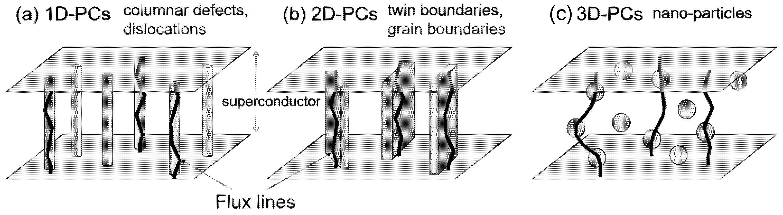
Figure 2.
Schematic illustration of various configurations of CDs designed by heavy-ion irradiation: (a) continuous CDs parallel to the c-axis produced by standard irradiation, (b) direction-dispersed CDs installed by tuning the irradiation directions, (c) discontinuous CDs formed by adjusting irradiation energy to lower value.
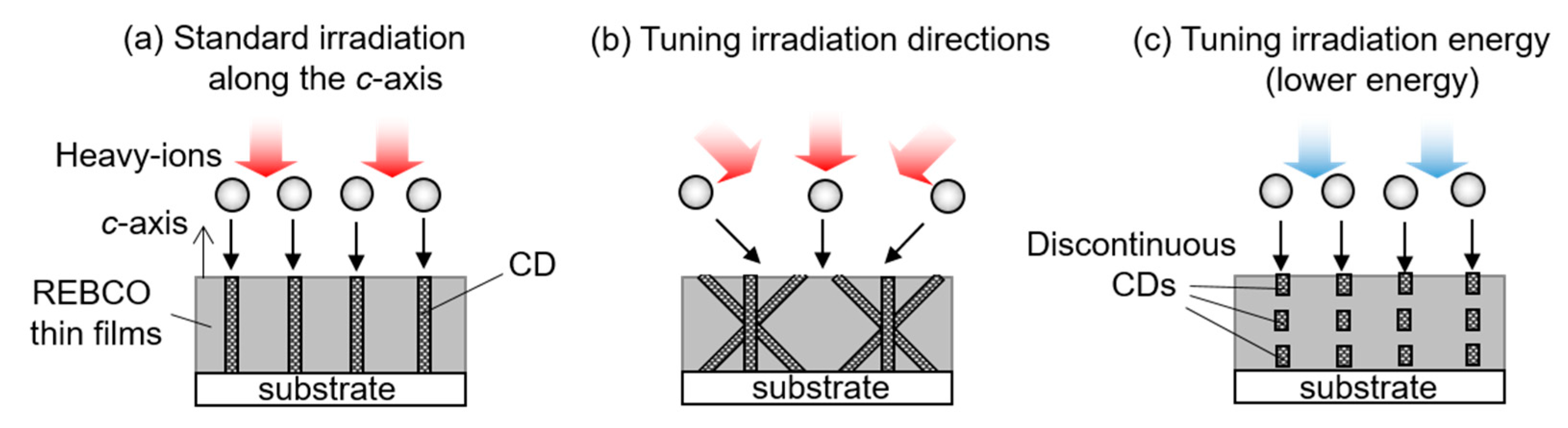
Figure 3.
Cross-sectional TEM images of GdBCO coated conductors irradiated with (a) 270 MeV and (b) 80 MeV Xe ions, respectively. The irradiation dose is 1.94 × 10¹¹ ions/cm2. The arrows indicate several ion tracks. Reprinted with permission from [25], copyright 2015 by IEEE.
Figure 3.
Cross-sectional TEM images of GdBCO coated conductors irradiated with (a) 270 MeV and (b) 80 MeV Xe ions, respectively. The irradiation dose is 1.94 × 10¹¹ ions/cm2. The arrows indicate several ion tracks. Reprinted with permission from [25], copyright 2015 by IEEE.

Figure 4.
Sketch of the experimental arrangement in this work.

Figure 5.
Schematic image of modification of the Jc anisotropy by controlling the irradiation directions ((a) typical Jc anisotropy of unirradiated high-Tc superconductors, (b) modified Jc anisotropy with CDs along the c-axis, (c) modified Jc anisotropy with direction-dispersed CDs).
Figure 5.
Schematic image of modification of the Jc anisotropy by controlling the irradiation directions ((a) typical Jc anisotropy of unirradiated high-Tc superconductors, (b) modified Jc anisotropy with CDs along the c-axis, (c) modified Jc anisotropy with direction-dispersed CDs).

Figure 6.
Magnetic field angular dependence of Jc normalized by the self-magnetic-field critical current density Jc0 for YBCO thin films with the crossed CDs (c10-2: θi = ±10°, c25-2: θi = ±25°, c45-2: θi = ±45°, p06-2: parallel CD configuration of θi = 6°, and Pure: unirradiated samples). Reprinted with permission from [28], copyright 2016 by IOP.

Figure 7.
Sketch of CDs dispersed in geometry of “another” trimodal-configuration, where a splay plane defined by the three irradiation angles is parallel to the transport current direction. Reprinted with permission from [32], copyright 2016 by IOP.
Figure 7.
Sketch of CDs dispersed in geometry of “another” trimodal-configuration, where a splay plane defined by the three irradiation angles is parallel to the transport current direction. Reprinted with permission from [32], copyright 2016 by IOP.

Figure 8.
Magnetic-field angular dependence of Jc normalized by the self-magnetic-field critical current density Jc0 for YBCO thin films with various CD configurations (Pure: unirradiated samples, Para: parallel CD configuration of θi = 0°, Standard: standard trimodal-configuration, and Another: another trimodal-configuration). Reprinted with permission from [32], copyright 2016 by IOP.
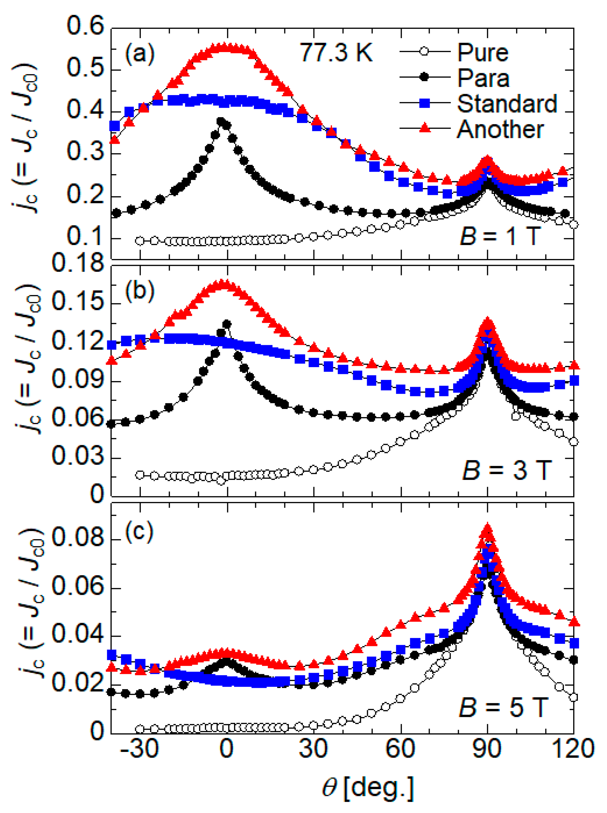
Figure 9.
Bright field TEM image showing CDs tilted at θi = 0°, ±30° and ±60° relative to the c-axis of the YBCO film, which are installed by 200 MeV Xe ion irradiation. The arrows indicate several ion tracks. Reprinted with permission from [36], copyright 2018 by IOP.
Figure 9.
Bright field TEM image showing CDs tilted at θi = 0°, ±30° and ±60° relative to the c-axis of the YBCO film, which are installed by 200 MeV Xe ion irradiation. The arrows indicate several ion tracks. Reprinted with permission from [36], copyright 2018 by IOP.

Figure 10.
Magnetic-field angular dependence of Jc (upper, (a)) and n-value (lower, (b)) for YBCO thin films with various CD configurations (Unimodal: parallel CD configuration with θi = 0°, Trimodal: trimodal-configuration with θi = 0° and ±30°, and Quintmodal: quintmodal-configuration with θi = 0°, ±30° and ±60°). The arrows indicate the peaks or the shoulder on the n(θ) curve for Quintmodal. Reprinted with permission from [37], copyright 2013 by IEEE.

Figure 11.
Magnetic-field angular dependence of Jc at temperature of 60 K and magnetic field of 3 T to 7 T for YBCO thin films with CDs crossing at (a) θi = ±30° and (b) ±60° relative to the c-axis, respectively. Reprinted with permission from [36], copyright 2018 by IOP.
Figure 11.
Magnetic-field angular dependence of Jc at temperature of 60 K and magnetic field of 3 T to 7 T for YBCO thin films with CDs crossing at (a) θi = ±30° and (b) ±60° relative to the c-axis, respectively. Reprinted with permission from [36], copyright 2018 by IOP.
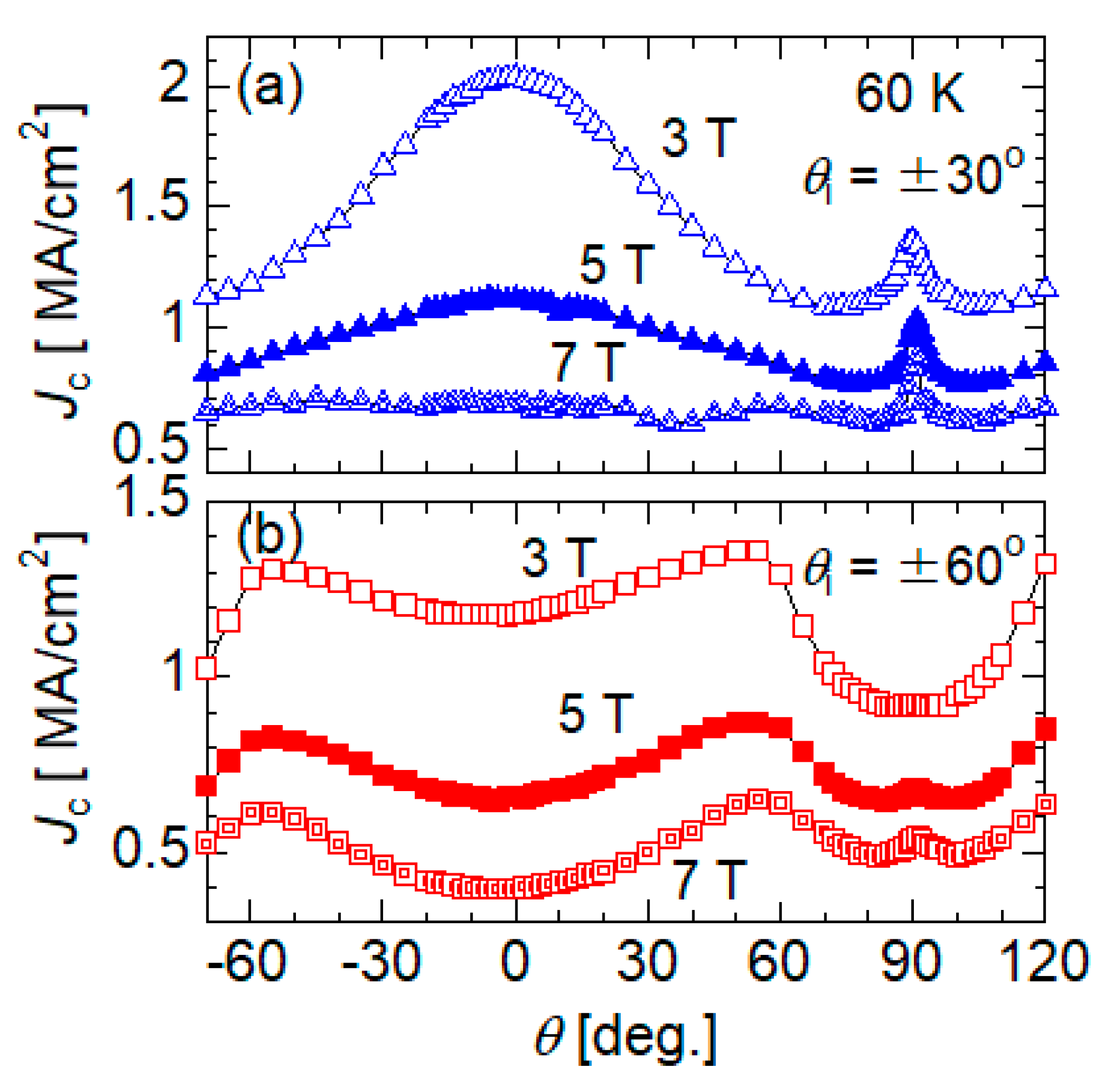
Figure 12.
Cross-sectional TEM images of a GdBCO coated conductor irradiated with 270 MeV Xe ions at Θi = ±10° relative to the ab-plane (a) near the surface and (b) at the bottom part of GdBCO layer, respectively. The arrows show several ion tracks. Reprinted with permission from [41], copyright 2017 by IEEE.

Figure 13.
Magnetic-field angular dependence of Jc at 77.3 K, 1.5 T in GdBCO coated conductors with crossed CDs at ±Θi relative to the ab-plane ((a) Θi = ±15°, (b) Θi = ±10°, and (c) Θi = ±5°). The broken lines are drawn at the positions of the irradiation angles. Reprinted with permission from [41], copyright 2017 by IEEE.

Figure 14.
Sketch of the experimental arrangement using the in-plane aligned a-axis-oriented YBCO film. Reprinted with permission from [43], copyright 2019 by IEEE.
Figure 14.
Sketch of the experimental arrangement using the in-plane aligned a-axis-oriented YBCO film. Reprinted with permission from [43], copyright 2019 by IEEE.

Figure 15.
X-ray diffraction θ-2θscan of the in-plane aligned a-axis oriented YBCO thin film before the irradiation. Inset: X-ray φ scan using (102) plane of the YBCO thin film before the irradiation. Reprinted with permission from [43], copyright 2019 by IEEE.
Figure 15.
X-ray diffraction θ-2θscan of the in-plane aligned a-axis oriented YBCO thin film before the irradiation. Inset: X-ray φ scan using (102) plane of the YBCO thin film before the irradiation. Reprinted with permission from [43], copyright 2019 by IEEE.

Figure 16.
(a) Cross-sectional and (b) plan-view TEM images of the a-axis oriented YBCO thin film irradiated with 200 MeV Xe ions along the a-axis. The arrows indicate several ion tracks. Reprinted with permission from [43], copyright 2019 by IEEE.
Figure 16.
(a) Cross-sectional and (b) plan-view TEM images of the a-axis oriented YBCO thin film irradiated with 200 MeV Xe ions along the a-axis. The arrows indicate several ion tracks. Reprinted with permission from [43], copyright 2019 by IEEE.

Figure 17.
Magnetic field dependence of Jc at B || c and at B || a in the a-axis oriented YBCO thin film before and after the irradiation. Inset: Jc normalized by self-field critical current density Jc0 as a function of magnetic field along the a-axis. Reprinted with permission from [43], copyright 2019 by IEEE.

Figure 18.
Schematic images of flux pinning peculiar to discontinuous CDs. (a) Ends of the discontinuous CDs work as PCs in magnetic field tilted off their long axis, which provide effective flux pinning over a wide magnetic field angular range. (b) Existence of gaps in the discontinuous CDs can suppress thermal motion of kinks of flux lines, which further improve Jc in comparison with continuous CDs.

Figure 19.
Magnetic field angular dependence of Jc at 4 T for the irradiated samples with 80 MeV and 270 MeV Xe ions ((a) 84 K and (b) 70K). Reprinted with permission from [25], copyright 2015 by IEEE.
Figure 19.
Magnetic field angular dependence of Jc at 4 T for the irradiated samples with 80 MeV and 270 MeV Xe ions ((a) 84 K and (b) 70K). Reprinted with permission from [25], copyright 2015 by IEEE.

Figure 20.
(a) Cross-sectional TEM image of the GdBCO coated conductor irradiated with 80 MeV Xe ions at θi = 0° and ±45°. Several continuous CDs are indicated by the solid arrows and discontinuous CDs along the c-axis are indicated by the dotted arrows. (b) Schematic image emphasizing the morphologies of CDs in the cross-sectional TEM image. Reprinted with permission from [50], copyright 2020 by the Japan Society of Applied Physics.

Figure 21.
Magnetic field angular dependence of Jc at magnetic field of 4 T and temperatures of (a) 84 K, (b) 77.3 K, and (c) 70 K for GdBCO coated conductors irradiated with 80 MeV and 270 MeV Xe ions, where the irradiation angles are θi = 0° for parallel CD configurations and θi = 0°, ±45° for trimodal angular configurations, respectively. The broken lines for (b) 77.3 K and (c) 70 K show the Jc properties of the unirradiated sample as reference data. Reprinted with permission from [50], copyright 2020 by the Japan Society of Applied Physics.
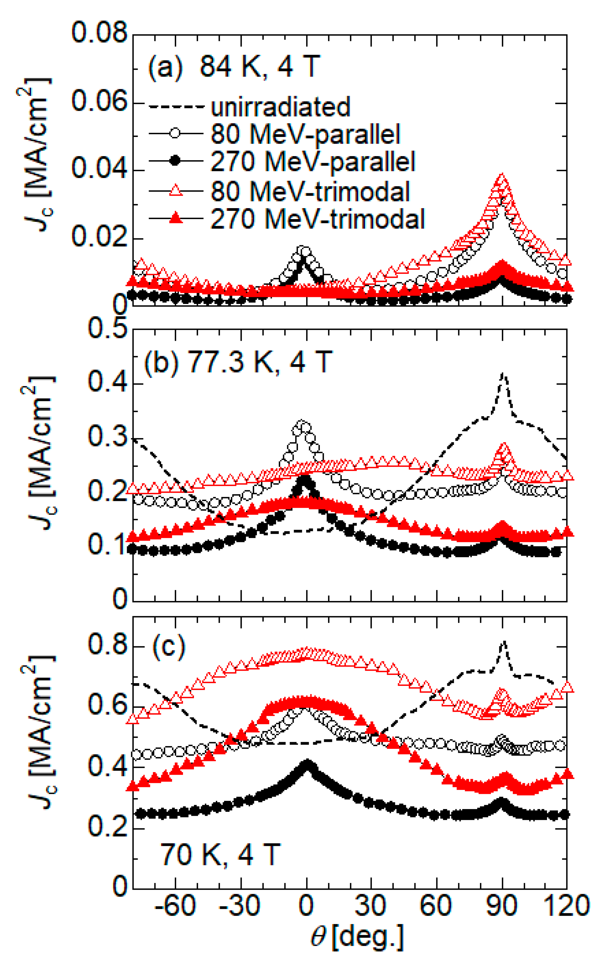
Figure 22.
Schematic images of flux pinning for the 80 MeV trimodal angular configuration in a magnetic field B (a) along the c-axis and (b) in the intermediate angular region between B || c and B || ab. The hatched regions in the inclined CDs and the discontinuous ones represent the interaction areas with kinks of flux lines. Reprinted with permission from [50], copyright 2020 by the Japan Society of Applied Physics.
Publisher’s Note: MDPI stays neutral with regard to jurisdictional claims in published maps and institutional affiliations. |
© 2021 by the author. Licensee MDPI, Basel, Switzerland. This article is an open access article distributed under the terms and conditions of the Creative Commons Attribution (CC BY) license (https://creativecommons.org/licenses/by/4.0/).
Share and Cite
MDPI and ACS Style
Sueyoshi, T. Modification of Critical Current Density Anisotropy in High-Tc Superconductors by Using Heavy-Ion Irradiations. Quantum Beam Sci. 2021, 5, 16. https://0-doi-org.brum.beds.ac.uk/10.3390/qubs5020016
AMA Style
Sueyoshi T. Modification of Critical Current Density Anisotropy in High-Tc Superconductors by Using Heavy-Ion Irradiations. Quantum Beam Science. 2021; 5(2):16. https://0-doi-org.brum.beds.ac.uk/10.3390/qubs5020016
Chicago/Turabian StyleSueyoshi, Tetsuro. 2021. "Modification of Critical Current Density Anisotropy in High-Tc Superconductors by Using Heavy-Ion Irradiations" Quantum Beam Science 5, no. 2: 16. https://0-doi-org.brum.beds.ac.uk/10.3390/qubs5020016