1. Introduction
Micro/nano-sized wire and cone structures of platinum directly integrated with a conducting substrate have several advantages for electrocatalytic performance [
1,
2,
3]. First, the large surface areas accelerate the surface reaction. Second, the open spaces among the nanostructures lead to efficient mass transfer. Third, the direct contact with the electrolyte as well as with the substrate makes mixing with a polymer binder unnecessary in electrode production. The resulting binder-free architecture is expected to maintain a high electric conductivity and effectively avoid blocking the active sites. Among various nanostructures, the cone shape enhances the mechanical stability because it has not only a fine tip but also a large base.
One of the methods to prepare metal micro/nanocones is the deposition of metal in a template with conically shaped pores; different techniques using electrodeposition or electroless deposition can be employed. Electroless deposition does not require conducting substrates; however, the surface must be pretreated with Sn
2+, Ag, or Pd via a sensitization and activation processes [
4]. Consequently, these metal ions and atoms are left as contaminants on the surface of the cones and thus affect their electrocatalytic performance [
5,
6] On the other hand, electrodeposition requires no pretreatment steps and therefore enables the fabrication of metal-contaminant-free platinum cones.
The most commonly used templates are anodic porous alumina and track-etched membranes [
7,
8]. Our particular interest is focused on track-etched membranes with nanometer-to-micrometer pores, which are prepared by the swift-heavy-ion irradiation of polymer films followed by chemical etching. This is because the ion-track technique offers flexible porous templates with large areas and enables the adjustment of the shape, size, orientation and density of the pores independently by varying the conditions of the irradiation and chemical etching.
To date, studies have been conducted on the fabrication of track-etched membranes with various shapes and configurations. For example, Rauber et al. reported a modified template fabrication method for the preparation of 13–44.2-nm-thick platinum wire networks, which involved ion-irradiation in several steps from different directions [
9]. Cylindrical, conical and double-cone-shaped pores were prepared with diameters of approximately 500–1500 nm by a multi-step etching technique, penetrating through a polyethylene terephthalate (PET) membrane of a 12 μm thickness [
10]. In order to make the conically shaped pores as a template, chemical etching is usually performed with an etchant on one side of the membrane and a stop solution on the other [
11]. For the subsequent electrodeposition of the desired metal, one side of the track-etched membranes is then sputter-coated with a thin metal layer to prepare the cathode [
11,
12]. In this conventional method using penetrating pores (also called through-holes), the length of the fabricated micro/nanostructures is always equal to the thickness of the track-etched membranes and is never controlled in principle. In contrast, a track-etched membrane with non-penetrating pores can be used for the preparation of cones with a controlled length, thereby enhancing the degree of freedom in the electrocatalyst’s design and production. Until the present time, gold cones were fabricated by electroless deposition using a track-etched membrane template with non-penetrating pores, which had diameters and depths in the range of 1–8 μm and 1–11 μm, respectively [
13].
In this study, platinum cones were fabricated by an electrodeposition method using track-etched membranes with non-penetrating pores. The size and shape of the template pores were controlled by the etching time and etchant concentration, thereby enabling the preparation of platinum cones with different base diameters and lengths. Finally, we demonstrated their higher electrocatalytic activity by the electro-oxidation of ethanol.
2. Experimental
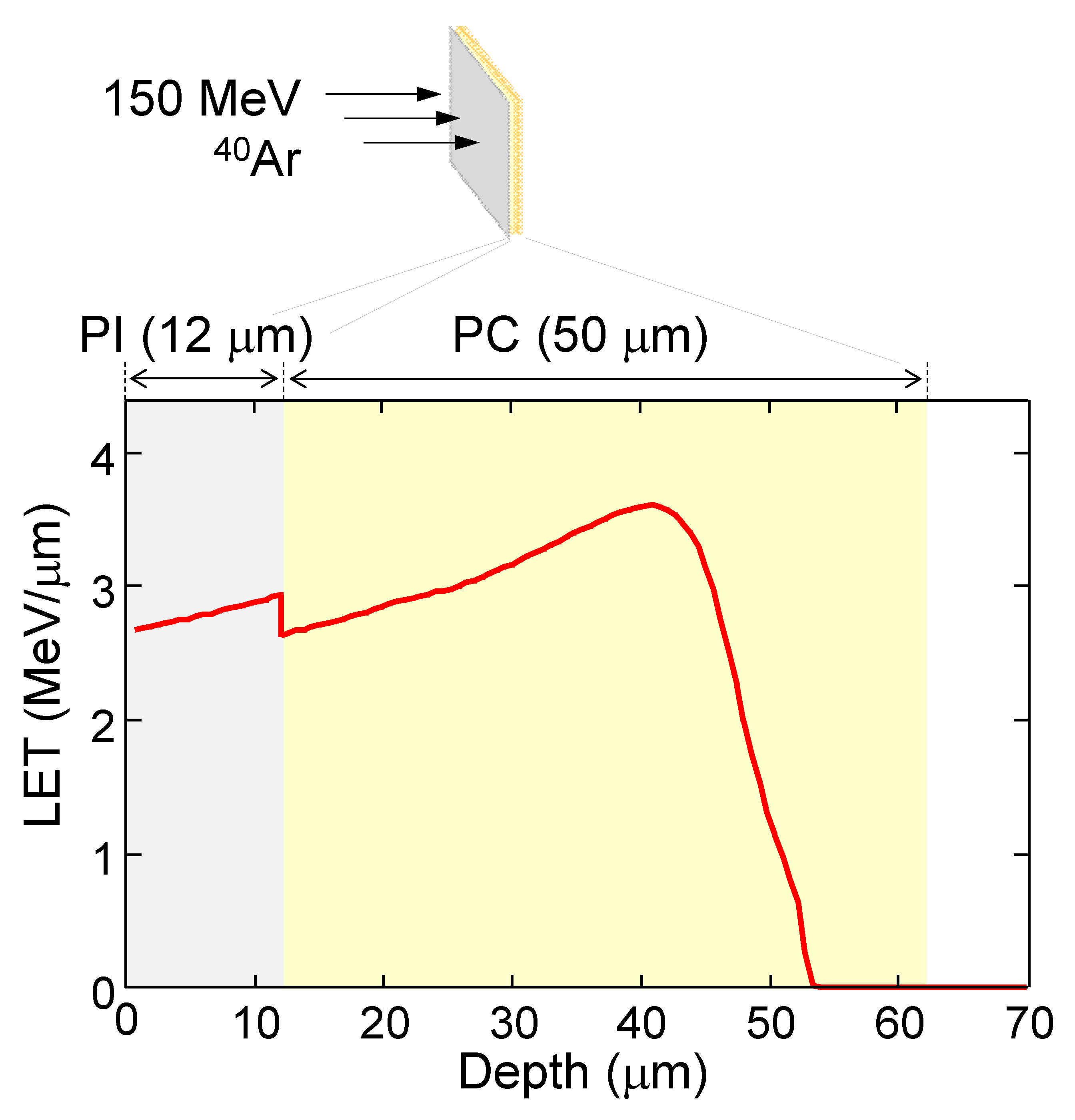
A stack of two polymer films, a polyimide (PI) film (Kapton, DuPont-Toray Co., Ltd., Tokyo, Japan) with a thickness of 12 µm on a polycarbonate (PC) film (Panlite, Teijin Ltd., Tokyo, Japan) of a 50 µm thickness, was irradiated with
40Ar ions at an energy of 150 MeV using the azimuthally varying field (AVF) cyclotron at Takasaki Ion Accelerators for Advanced Radiation Application (TIARA).
Figure 1 depicts the depth profile of the linear energy transfer (LET) of the
40Ar ion calculated by the Stopping and Range of Ions in Matter (SRIM) code [
14], together with the configuration for the irradiation of the first 12 μm-thick PI and the second 50 μm-thick PC films. The stopping depth was 54 µm from the front surface, meaning that the impinging ion penetrated through the first PI film and stopped in the second PC film. Consequently, we employed the present irradiation configuration. The track etching of the PC film irradiated in this way started from one side, yielding non-penetrating conical pores. The number of irradiated ions per 1 cm
2, namely the ion fluence, was fixed at 3.0 × 10
7 and 1.0 × 10
8 ions/cm
2.
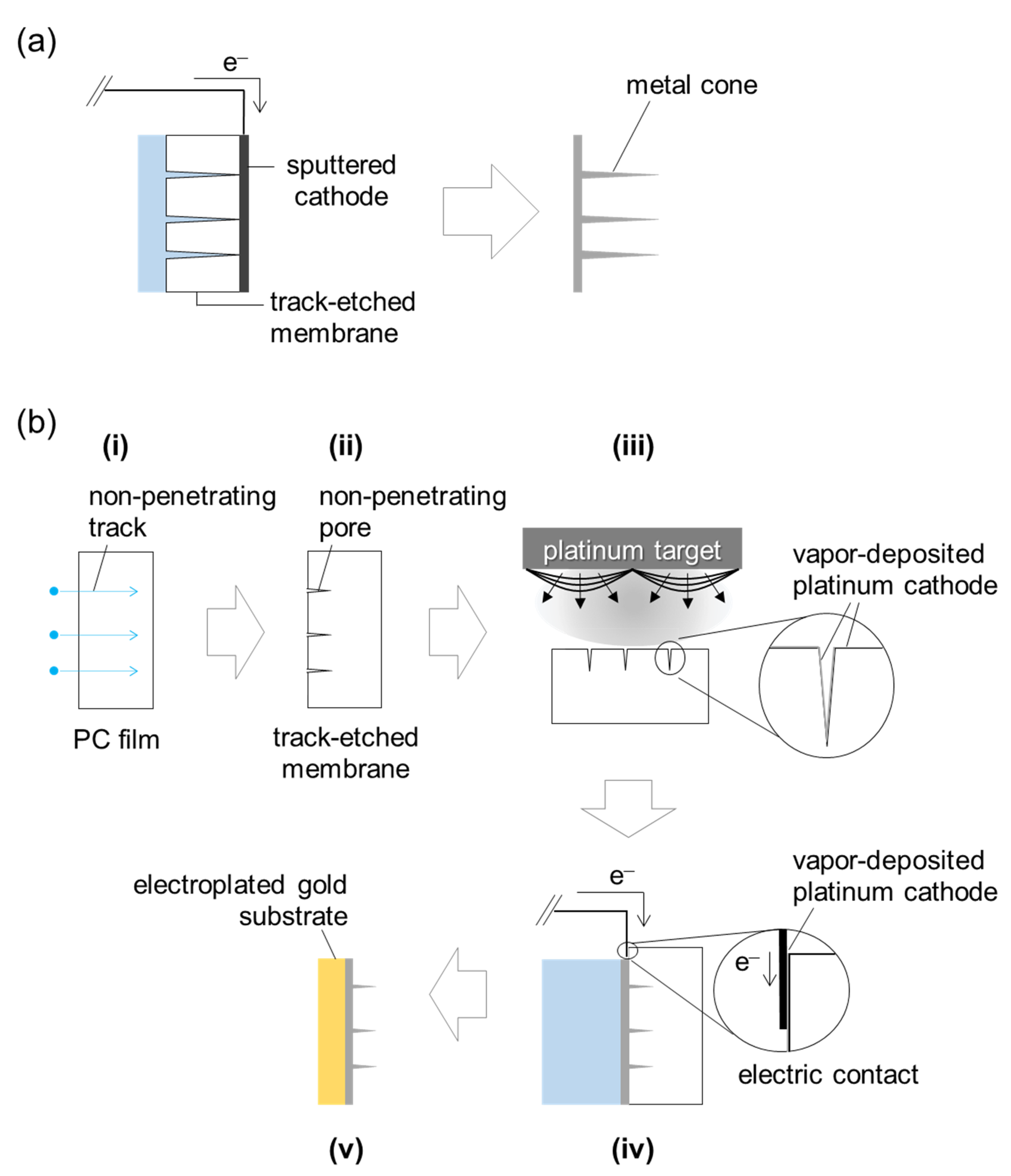
Figure 2 shows the preparation procedure, which involved filling the non-penetrating pores of track-etched membranes with electroplated platinum. After the
40Ar irradiation, the PC films were etched in 2.0, 4.0 and 6.0 mol/dm
3 aqueous NaOH solutions at 60 °C. The etched films were then washed with water and dried at room temperature. The surface and cross-section of the track-etched membranes were observed by field emission scanning electron microscopy (FE-SEM) (JSM-6700F, JEOL Ltd., Tokyo, Japan). Before the observation, a thin gold layer was deposited on the sample surface to improve its conductivity. In order to create the fine cross-section of the etched pores, the membranes were embrittled by exposure to UV light [
10].
For the electrodeposition, the track-etched membrane was physically coated with a thin platinum layer from its pore-open side; the current and time of the vapor deposition were 20 mA and 520 s, respectively. This layer reached a thickness of approximately 40 nm and worked as a cathode for the electrodeposition of the platinum cones in a commercial platinum electrolyte (PRECIOUSFAB Pt3000, Tanaka Kikinzoku Kogyo K.K., Tokyo, Japan) at 50 °C. The applied voltage was repeatedly pulsed at 1.8 V for 1 s and at 0 V for 2 s; the repetition number was 200 with a total deposition time of 10 min. After filling the non-penetrating pores with electroplated platinum from the bottom and reinforcement with a thick electroplated gold substrate, the track-etched membranes were dissolved in a 6.0 mol/dm3 aqueous NaOH solution at 60 °C, leaving the free-standing platinum cone array.
The obtained platinum cones were observed by FE-SEM and transmission electron microscopy (TEM) (JEM-2100F, JEOL Ltd., Tokyo, Japan). The elemental composition was investigated using an energy-dispersive X-ray (EDX) analyzer (X-Max, HORIBA Ltd., Kyoto, Japan). The electrochemical measurements were performed using a three-electrode cell at room temperature. The platinum cones were used directly as the working electrodes. A platinum foil and Ag/AgCl (KCl sat.) were used as the counter and reference electrodes, respectively. All of the potentials were converted to the reversible hydrogen electrode (RHE) scale according to the Nernst equation: E(RHE) = E(Ag/AgCl) + 0.059 × pH + 0.197. The electrochemically active surface area (ECSA) of the platinum was measured by an established procedure using cyclic voltammetry (CV) [
15]. The potential of the working electrode was scanned from 0.02 to 1.17 V vs. RHE at a scan rate of 50 mV/s in a N
2-saturated 0.5 mol/dm
3 aqueous H
2SO
4 solution. The coulombic charge corresponding to the adsorption peak of atomic hydrogen,
QPt-H, was estimated by integrating the CV curve in the hydrogen underpotential deposition region. Assuming a coulombic charge of 0.21 mC/cm
2 for hydrogen adsorption on a smooth polycrystalline platinum surface, we used the equation ECSA (cm
2) =
QPt-H/0.21. Subsequently, in order to measure the ethanol oxidation reaction activity, the CV was performed in a N
2-saturated aqueous solution containing 0.5 mol/dm
3 ethanol and 0.5 mol/dm
3 H
2SO
4. The electrode was cycled in the potential range from 0 to 1.2 V vs. RHE at a scan rate of 20 mV/s.
3. Results and Discussion
Figure 3 shows the FE-SEM images of the surface and cross-section of the PC membrane etched for 30 min in a 4.0 mol/dm
3 aqueous NaOH solution. The membranes were found to have uniform conical pores. The surface diameter of the pores was roughly estimated to be 540 nm by taking the average of the neighboring 50 pores. On the other hand, the depth seemed scattered, which may have been because, in the sample preparation for our cross-sectional SEM observations, the membrane was not necessarily cracked exactly in the middle of the pore. Thus, we determined the maximum depth at which the resulting cut plane was assumed to pass through the close vicinity of the conical vertex.
Figure 3b presents the image of the best cut plane for the four pores, where the diameter of the pore opening was almost the same as the diameter measured on the surface (
Figure 3a). Thus, the tip would have been included. This resulted in a depth of 3.8 µm.
On the other side of the membrane, no pores were observed, confirming that the bombarded ions did not penetrate through the PC film, as calculated by the SRIM code. A previously proposed method for the fabrication of conically shaped pores that do not propagate through the entire thickness, that is, non-penetrating conical pores, involves the chemical etching of the penetrating tracks only from one side of the irradiated film and its stopping before the etchant breaks through to the opposite side [
13]. In this method, a compression-sealed two-component cell must be employed to avoid the contact of another side with the etchant during the one-side etching [
16]. However, we obtained non-penetrating conical pores even without such a dedicated cell and special care for the etching. This is because the tracks in the PC film did not propagate through its entire thickness. The immersion of the irradiated films in the etchant resulted in track-etched membranes with non-penetrating conical pores.
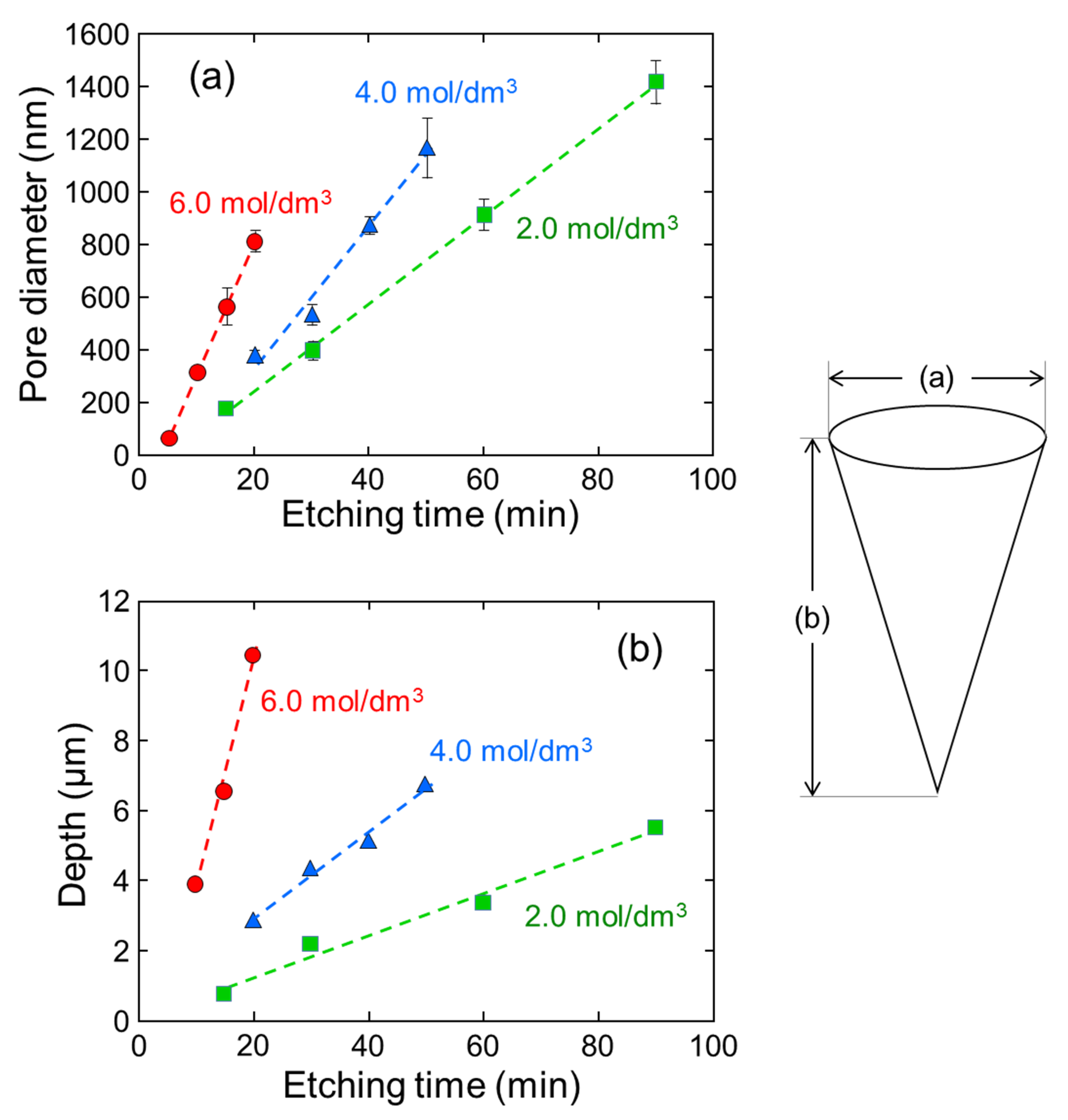
Non-penetrating conical pores were prepared by varying the etching time and etchant concentration.
Figure 4 plots the pore diameter and depth as a function of the etching time for different concentrations of the NaOH solutions. In
Figure 4a, the surface diameter is observed to be uniform with rather small error bars under all of the etching conditions. As mentioned above, the maximum depth was taken for at least 20 pores; thus,
Figure 4b plots the depth with no error bars. The diameter and depth of the pores linearly increase with the etching time; therefore, the slope of the plots corresponding to the growth rate of the pores was estimated by least-squares regression. At concentrations of 2.0, 4.0 and 6.0 mol/dm
3, the pore diameter was enhanced at 16, 26 and 50 nm/min, while the pore depth increased more significantly at 60, 130 and 660 nm/min, respectively. Consequently, the pore diameter and depth were controlled by a combination of the etching time and the NaOH concentration.
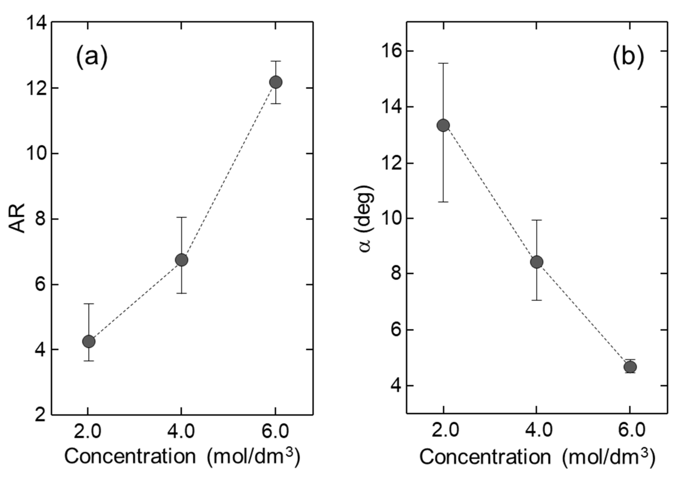
Figure 5 depicts the aspect ratio (AR) [
17] and the cone angle, α, [
18] of the conical pores, which are defined as the ratio of the depth to the surface diameter and the angle between two generatrix lines, respectively. Based on the assumption of a perfect conical geometry, the α values were calculated by the relationship α = 2tan
−1(1/AR). For example, these were estimated to be 6.8 and 8.4°, respectively, for the pores shown in
Figure 3. For all of the etching times, we observed their average values change from 4.3 to 12.2 and from 13.3° to 4.7°, respectively, with the increase of the concentration of the aqueous NaOH solution from 2.0 to 6.0 mol/dm
3. This concentration dependence can be rationalized by considering that the etch rate in the depth direction was more sensitive to the NaOH concentration than that in the transverse direction, as discussed earlier. More importantly, the AR and α, as well as the diameter and depth of the conical pores, were controlled by adjusting the etchant concentration.
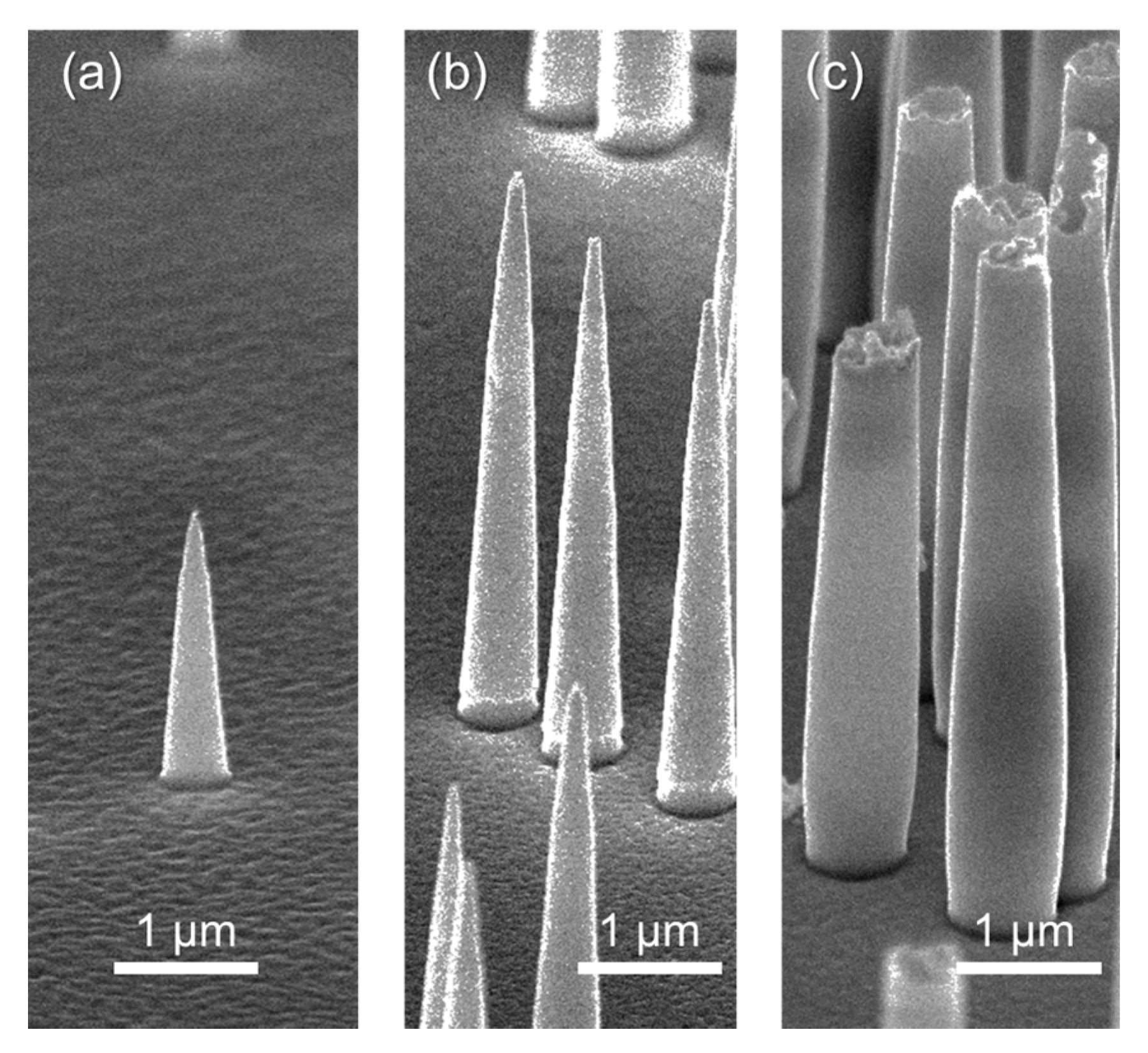
Track-etched membranes with non-penetrating conical pores were used for the fabrication of the platinum cones.
Figure 6a–c depicts the FE-SEM images of the platinum cone arrays obtained using the template membranes etched for 30 min in the 2.0, 4.0 and 6.0 mol/dm
3 NaOH solutions, respectively. The platinum cones shown in
Figure 6b have base diameters and lengths of 540 nm and 3.7 µm, respectively, both of which agree well with those of the template shown in
Figure 1. The same is the case for the platinum cones shown in
Figure 6a. In contrast, we obtained truncated platinum cones, as shown in
Figure 6c, using the conical pores with the highest aspect ratio as a template. The vapor-deposited platinum cathode could not reach the bottom of the pores, which is likely because the platinum atoms and ions sputtered from the target arrived inside the conical pores from random directions [
19,
20].
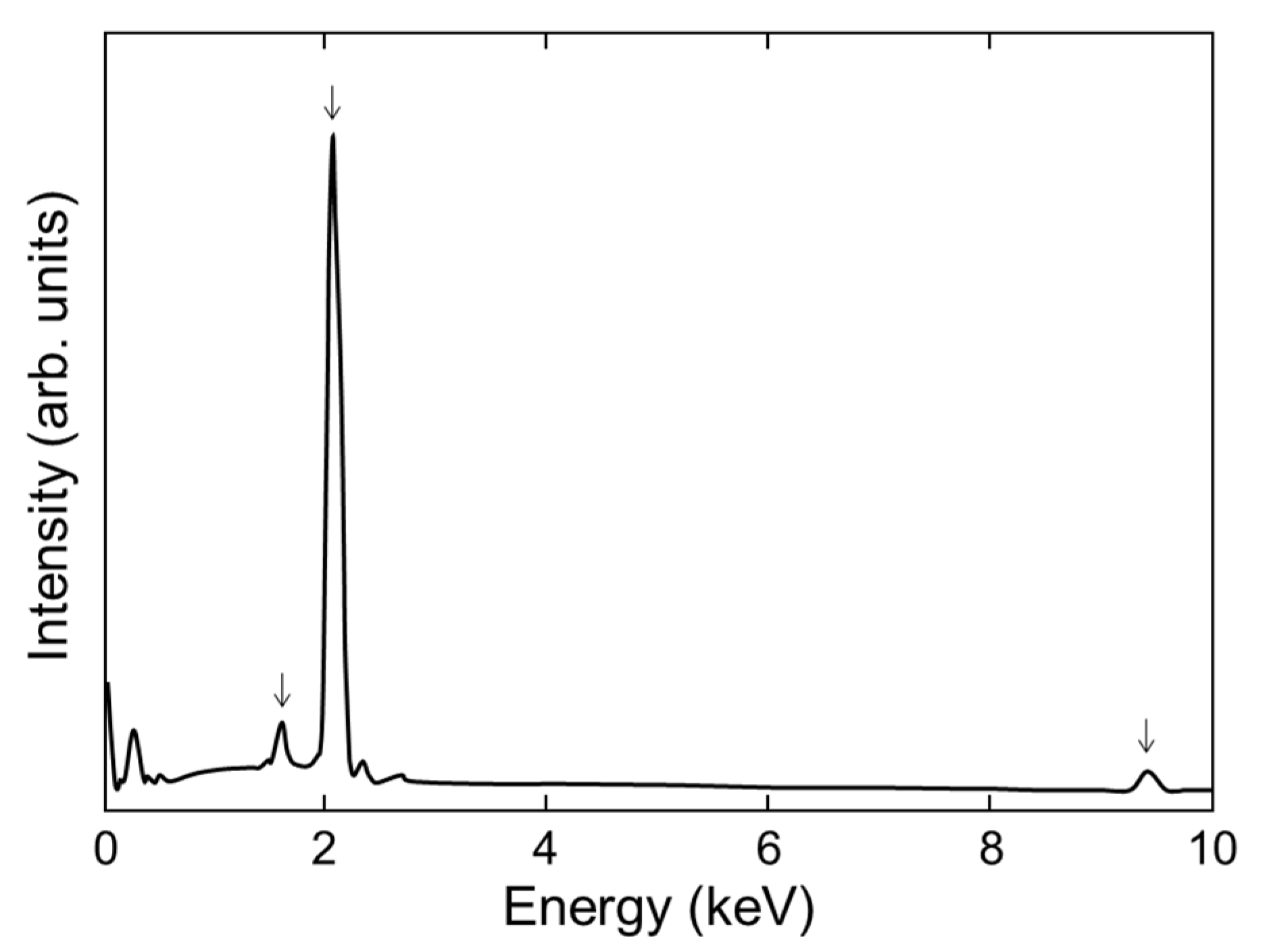
Figure 7 depicts the EDX spectrum of the platinum cones. The platinum signals were observed at 9.42 keV (L
α line), 2.04 keV (M
α + M
β line) and 1.59 keV (M
ξ line). Meanwhile, the other emission lines were assigned to the non-metal components, likely from the electrolyte solution PRECIOUSFAB Pt3000, e.g., carbon, nitrogen, oxygen, sulfur, and chlorine. In the electroless deposition method, the other signals of the minor components, such as Sn and Ag, were observed [
4]. The platinum cones without any metal contaminations were fabricated by a combination of ion-track etching with the electrodeposition technique.
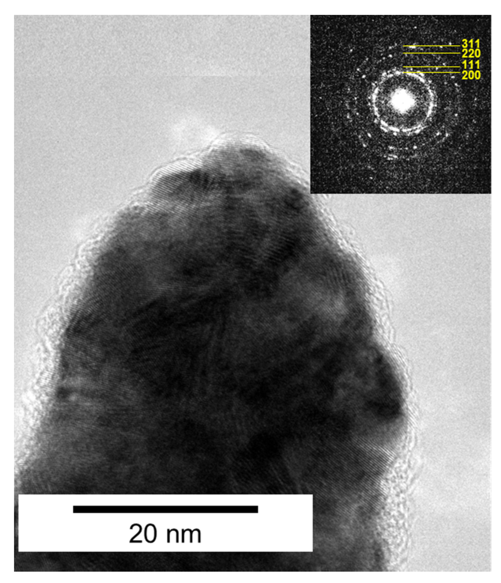
The platinum cones were further analyzed using TEM.
Figure 8 shows a TEM image of the tip area of the cones shown in
Figure 6b. The radius of curvature of the tip was 13 nm. The selected-area electron diffraction pattern in the inset of
Figure 8 exhibits concentric rings composed of bright, discrete diffraction spots that were indexed to the (111), (200), (220), and (311) crystal planes of fcc platinum, indicating the polycrystalline structure of the individual cones.
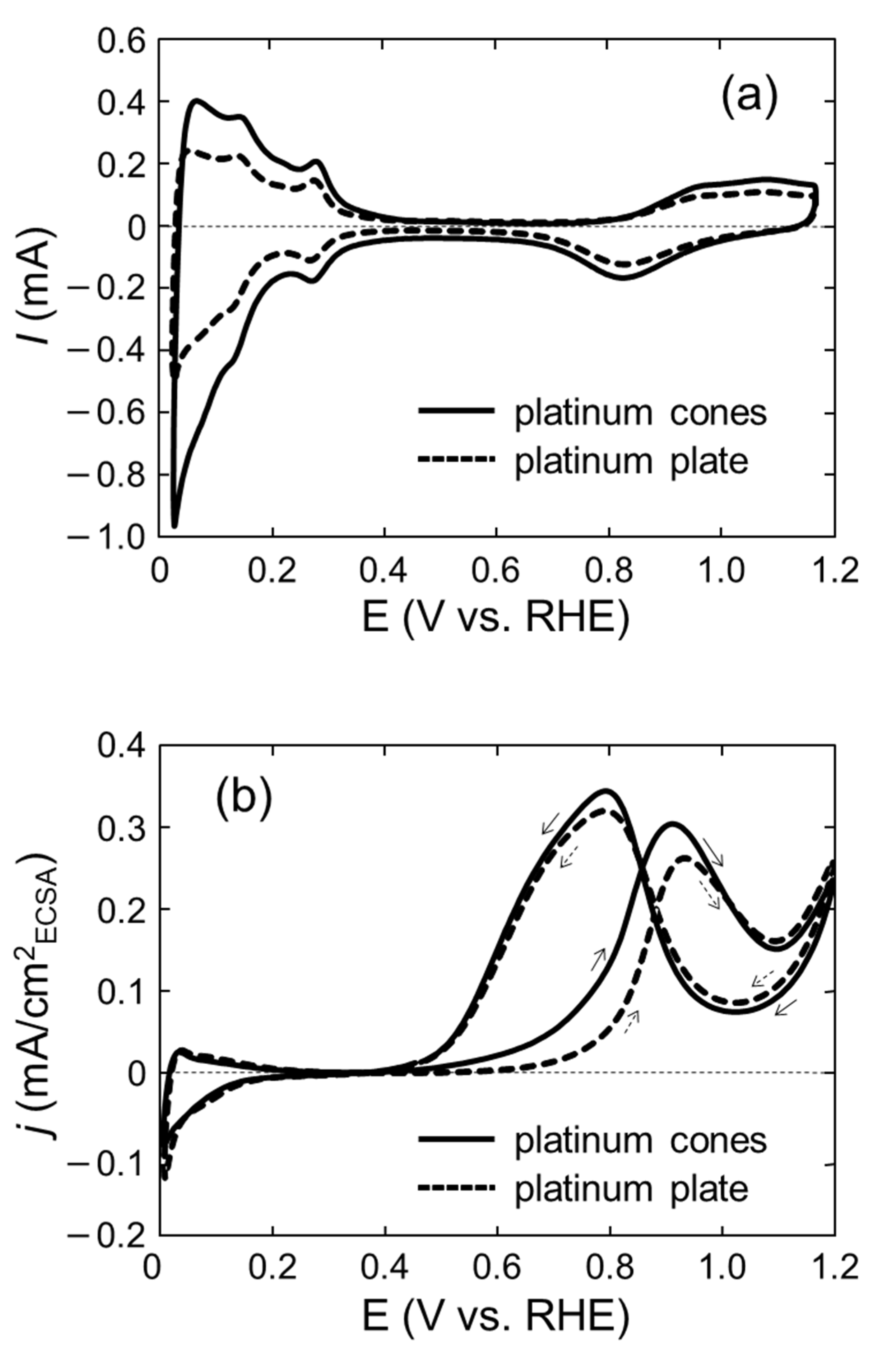
Figure 9a shows the cyclic voltammograms obtained in a 0.5 mol/dm
3 aqueous H
2SO
4 solution. The base diameter, length and areal density of the platinum cones are 550 nm, 2.4 µm and 1.0 × 10
8/cm
2, respectively. In this areal density, nearly half of the cones could be isolated, while the remaining ones may overlap to form multiple (mainly double) cones according to the calculation using a Poisson distribution model [
21]. For comparison, the platinum plate with a diameter of 1.5 cm was fabricated by electrodeposition on the PC film without any etched pores, and its circular portion (0.8 cm in diameter) was measured in the same way. Both of the samples exhibited a hydrogen adsorption and desorption region at 0.02–0.4 V vs. RHE and a double layer plateau region at 0.4–0.6 V vs. RHE with peaks for the formation and reduction of surface platinum oxide at 0.6–1.17 V vs. RHE. The ECSA for the hydrogen adsorption was 1.8 times higher for the cones than for the plate. In a previous paper [
15], the surface area resulting from the double-layer capacitance was estimated for comparison with the ECSA. This was determined by the non-Faradaic double-layer charging current around 0.5 V vs. RHE. It was approximately 1.7 times higher for the platinum cones than for the plate; therefore, the increase in the ECSA could reasonably be accounted for within the allowable error.
The electrocatalytic performance for ethanol oxidation was demonstrated by CV in an aqueous solution containing 0.5 mol/dm
3 ethanol and 0.5 mol/dm
3 H
2SO
4. The CV curves of the platinum cones and platinum plate are shown in
Figure 9b. The current in the forward scan exhibited the oxidation of ethanol, whereas in the backward scan, another oxidation current was observed, which was associated with the oxidation of intermediates of ethanol dissociative adsorption [
22]. The ECSA-normalized current densities (called specific currents) at 0.7 V vs. RHE were extracted and compared with those of platinum on carbon (often referred to as Pt/C) and platinum black found in a study by Mao and co-workers [
23]. The platinum cones and plate indicated approximately 0.06 and 0.02 mA/cm
2, respectively, whereas both of the commercial products exhibited 0.06–0.07 mA/cm
2. The only difference between our measurements and theirs was the ethanol concentration, and the CV curve was recorded in an aqueous solution containing 2 mol/cm
3 ethanol and 0.5 mol/cm
3 H
2SO
4. The twofold higher ethanol concentration would lead to an increase in the current density because it likely related to a greater amount of electroactive species in the solution [
24]. Therefore, our platinum cones could exhibit the best performance among these four samples.
It should be emphasized that the current density was 3.2 times higher for the platinum cones than for the platinum plate. This comparison leads to the assumption that the cone structure contributes to the improvement of the electrocatalytic activity. The high electrocatalytic activity may be exhibited by the field-induced reagent concentration [
25,
26]. In other words, the polar ethanol molecules are likely to approach the surface of the cone electrode because the fine tips of the cones produce high local electrical fields. Finally, we demonstrated the fabrication of platinum cones by ion-track etching and electrodeposition techniques and found them to be a promising alternative for ethanol oxidation electrocatalysts.


