
MeV Cluster Ion Beam–Material Interaction

Graduate School of Science, Okayama University of Science, Okayama 700-0005, Japan
Quantum Beam Sci. 2022, 6(1), 6; https://0-doi-org.brum.beds.ac.uk/10.3390/qubs6010006
Submission received: 31 October 2021
/
Revised: 3 January 2022
/
Accepted: 11 January 2022
/
Published: 24 January 2022
(This article belongs to the Special Issue Swift Cluster Ion Beams: Basic Processes and Applications)
Abstract
:This paper treats the characteristic topics of MeV/atom cluster ion beams produced using tandem accelerators both in the production stage and in the penetration stage from the viewpoint of fundamental processes. The former is related to atomic collisions in that production and decay of a cluster ion colliding with a charge-changing rare gas underlined through the electron-loss process. Regarding the latter, relatively small carbon clusters are treated. The reduction effect of the average charge of cluster ions in a material is first presented. Next, the electronic stopping power and the energy loss, the polarization force, and the coulomb explosion under cluster-ion impact are described in the dielectric function form. Alignment and structure effects are stressed. As a large and highly symmetric cluster, the electronic stopping power and the average charge are shown for a C60 cluster ion moving inside a solid. Throughout the paper, it is emphasized that the vicinage effect originating from correlation on spatial structure and orientation of constituent ions plays the key role. Moreover, results obtained in cluster production and penetration phenomena are mostly different from multiplication of those under single-ion impact.
1. Introduction
Since the development of accelerators, controlled single-ion beams have been intensively utilized in various fields of application, e.g., surface analysis, ion implantation, material modification, and cancer therapy. Basic and essential phenomena working on these fields are elastic and inelastic collisions, on which the theories in the early stage [1,2,3] were instructive. After that, the knowledge accumulated for a long time on the stopping powers of materials for single ions and their ranges were compiled as a series of data book [4] and have been utilized in SRIM computer code [5]. Here, the average charge of a moving single ion, which is representative of the charge of a moving ion inside a material, is a characteristic quantity because it governs the coupling strength of the ion-material interaction. The compiled data on the single ion intruder were published [6]. In these two decades, progress in technology has made it possible to research irradiation phenomena with polyatomic projectiles or cluster ions [7,8,9,10]. With this progress, new information has become available on the polyatomic irradiation effects such as the energy deposition rate (or LET), secondary particle emission, and fragmentation, which have never been gained by single-ion irradiation. In fact, under cluster-ion impact, unique phenomena have been reported, e.g., on the sputtering yields [11,12], reduction of average charge per atom [13,14,15,16,17], enhanced and suppressed energy losses [18,19,20,21,22,23,24], suppressed low-energy secondary electron emission [25,26,27], and enhanced convoy electron emission [21]. These situations intensively attract our attention to the size (the number of constituent atoms) of cluster ions and the spatial structures since those quantities are known to newly affect the irradiation effect. Moreover, MeV cluster ion beams were recently utilized to obtain SIMS (Secondary Ion Mass Spectroscopy) signals from biomolecule targets [28,29,30] and track formation in solids [31,32]. In addition, the SIMS yield depends on the structure and orientation of the incident carbon cluster ion [29,30]. Cluster ion impact has several advantages:
- Reduction of the kinetic energy per atom at a given accelerated voltage.
- Suppression of the charge-up effect at ion implantation.
- Performance of high-density particle irradiation.
On the other hand, regarding a projectile, the basic and elementary approach to description of ion beams is a point-charge picture, where only two parameters, i.e., net charge and speed, characterize the moving ion. This simple picture was extended to a dressed ion which has attached some bound electrons in a frozen state during the passage [33,34,35,36]. The average number and the spatial distribution of those electrons is included in the term ‘effective charge’. After that, using molecular ion beams, the number and spatial distribution of constituent ions/atoms play an important role in electron excitation. In a special case, the swift single and molecular ions in the frozen charge state provide us important information on the energy deposition to materials. Up to here, ion beams are characterized by net charge, speed, and spatial distribution of bound electrons.
As for cluster ion beams, two more parameters, i.e., the number of constituent atoms, and the spatial structure, are added to the previous three parameters. In basic viewpoints, these five elements cooperate with each other and display cluster impact phenomena. In fact, they cause a strong correlation in time and space in collision phenomena with electrons. A simple characteristic term to highlight cluster impacts is the quantity per atom, denoted by for a cluster impact and compared with for a single ion impact at equivalent speed, where the quantity is the average charge, the energy-loss, the secondary electron yield, etc. The term of positive (negative) cluster effect is used for the cases of () or (). Another identical term is the super-linear (sub-linear) dependence () on the number of atoms in a cluster.
Cluster-ion technology has been in progress and spread into wide ranges. Speaking of the application side, a lot of significant and interesting results have been obtained in various fields. It is not the purpose of this paper to pick up those things. I pick up, rather, the energy transfer to a target material because it is a dominant mechanism in cluster impact phenomena. Compared with single-ion impact, we have less ample information clarified on this process in spite of a lot of application works. This review is intended to make help early-career researchers grasp the cluster impact events comprehensively. The aim of this paper is to clarify the above-mentioned cluster effects from a theoretical point of view. The topics treated are the average charge, the energy loss via electron excitation, and some related quantities on the penetration stage, while the electron loss process is treated on the production stage. This paper presents the interaction of carbon cluster ions with materials at kinetic energies of MeV region. So, the speed of those ions is assumed to be around or higher than the Bohr speed. Carbon cluster ions are typical and representative projectiles. They are predicted to have several spatial structures, e.g., linear-chain, ring, and fullerene, with the adjacent-atomic separation of m (linear-chain and ring) and m (fullerene) [37]. These separations tend to correlate with electron excitation both at close and distant collision in materials, especially in solids. First, production and decay of MeV cluster ion beams is described in the production stage. The ion yield produced with a tandem accelerator depends on the pressure of charge-changing gas. The above-mentioned cluster effect in the cross sections will be shown in Section 2. In Section 3, the cluster average charge, the electronic stopping power, and related things are described in the penetration stage. Finally, the relation between the electronic stopping power and the secondary electron yield under cluster impact will be mentioned. Throughout the paper, the Bohr speed, the Bohr radius, and the Planck constant divided by , are denoted by m/s, m, and J·s, respectively.
2. Model for Production of Cluster-Ion Beam
This section is devoted to theoretical models, firstly describing swift cluster ions in collision with rare gases, which relates to controlled cluster ion beams produced in tandem accelerator, and secondly describing electron excitations in materials and friction forces induced by swift cluster ions. In the latter, the cluster effect in the average charge is also presented.
2.1. Production of Carbon Cluster Ion Beams
Swift (MeV/atom) cluster ion beams are mainly produced with Tandem accelerator facilities. Here, singly negative cluster ions, which are originated at the ion source, are firstly accelerated to the charge exchange region, and secondly, some of them are converted to singly positive charged cluster ions by passing through that region, and finally subtracted as a positive cluster ions beam after second acceleration. The production rate of utilized cluster ion beams is determined by production and destruction processes occurred in charge-exchange region. Then, we consider these processes on the basis of rate equation. The charge state fraction of a cluster in charge state at penetrating depth of charge-changing gas layer, is governed by the following equation:
Here and denote, respectively, the charge-changing cross section to charge state and the destruction cross section for a cluster in charge state in collision with a gas, and denotes the number of charge-changing gas atoms per unit volume. If we concentrate on the carbon cluster, MeV/atom corresponds to the speed . Then, for MeV/atom carbon cluster ions, the speed is greater than the Bohr speed so that the electron-loss process may be dominant in comparison with the electron capture process. Thus, under the initial condition , we obtained analytical expressions for . Especially, the fraction of singly charged cluster is given by three electron-loss cross sections, , and three destruction cross sections, as follows [38]:
where we use the symbols , .
Regarding relatively small clusters in which the number of the constituent atoms is small, the charge state fraction for clusters with more than +2e charge is negligibly small. However, in large clusters such as C60 fullerene ion, the fraction of doubly charged ions is not negligible. In this case, the rate equation should be extended to include . Under the similar initial condition , the analytical expressions could be obtained (see Appendix A).
2.2. Estimation of Cross Sections
Next, we move to consider how to estimate the cross sections for a carbon cluster ion. Carbon cluster ions are assumed to be composed of isolated atoms and ion, with a linear-chain structure of equal spacing of 2.4a0 [37]. To do this, three kinds of particles were prepared, i.e., a singly negative ion, a neutral atom, and a singly charged ion, for whose electrons the Roothaan–Hartree–Fock (RHF) atomic wave functions were tabulated by Clementi and Roetti [39]. As the electro-static interaction between a cluster and a rare gas is in very short range, we could adopt the binary collision scheme between a constituent atom/ion and a neutral gas. Then, we made use of the time-dependent perturbation method to estimate the electron stripping probability from a constituent atom/ion as a function of impact parameter b. Based on this quantity, we set the electron-loss probability from multiple atoms with multi-electrons in the independent-atom model (IAM) and the independent-electron model (IEM).
First, we explain the one electron-loss probability from a carbon atom/ion in collision with a rare gas. The problem is considered in the rest frame of a carbon atom/ion impacted by a rare gas moving with relative speed v along a straight-line trajectory with impact parameter b. The wave function of an active electron (i.e., ionized electron) is excited via the interaction potential energy between a moving neutral gas atom, denoted by position vector , and the active electron, denoted by position vector , of the form:
In the above, and denote atomic number of a rare gas and the number density of the bound electrons on the atom, respectively. According to first-order perturbation theory of the time-dependent Schrodinger equation, the transition probability at time from the initial state at time to the final (ionized) state is obtained by the following expression
Since , the above transition probability is a function of impact parameter vector . is given by the RHF wave-functions which are linear combinations of the slater-type functions, tabulated in the reference [39] and is described by a distorted plane wave with wave number , including a residual charge [40]. Thus, the one electron loss probability is obtained by integrating over as
for the electronic shell of the 1s, 2s, and 2p states in and [39].
Based on the above one electron loss probability for a single atom/ion, the independent electron model (IEM) and the independent atom model (IAM) allow us to define the multiple electron loss probabilities for cluster ions. For example, for a neutral carbon atom with two 2s and two 2p electrons, one-electron loss probability and no electron-loss probability at impact parameter b are given in the IEM by
where the 1s electrons are assumed frozen since they are hard to be lost much more than those in other states. For a cluster ion composed of two carbon atoms, the one electron loss probability is given in the IAM by
where refer to impact parameter with respect to atom 1 and atom 2, respectively, and they depend on the spatial arrangement of two atoms, i.e., cluster-axis orientation.
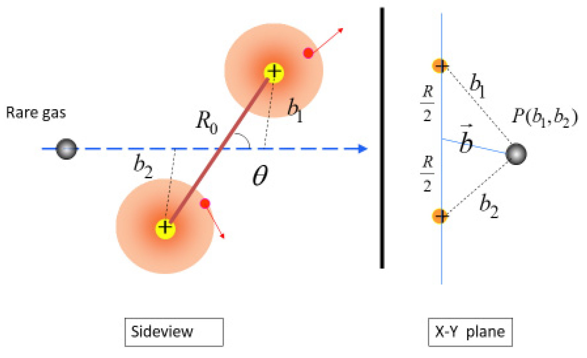
Then, if we assume that a trajectory of a projectile is a straight-line parallel to the z-axis, the projection of the trajectory on the xy plane is denoted by a 2D vector so that are functions of as
Here, is the distance between two atoms, and is the polar angle between the cluster axis and the z-axis (see Figure 1). As a function of , the one-electron loss cross section for the cluster of two carbon atoms is calculated in the following:
The cross section for a cluster is finally obtained by averaging over the polar angle as
For other electron loss processes, we can define in a similar manner the charge-changing cross sections, , for other carbon clusters. However, in order to avoid complexity, we dare not write them down in an explicit form. Regarding the destruction cross sections, , we took a position that small carbon cluster ions with more than or equal to +2e charge have not been reported up to now from the experimental viewpoint. Therefore, we assume that the destruction of clusters occurs when the resultant charge state of a cluster is equal to or greater than +2e.
2.3. Calculated Cross Sections and Charged Fraction
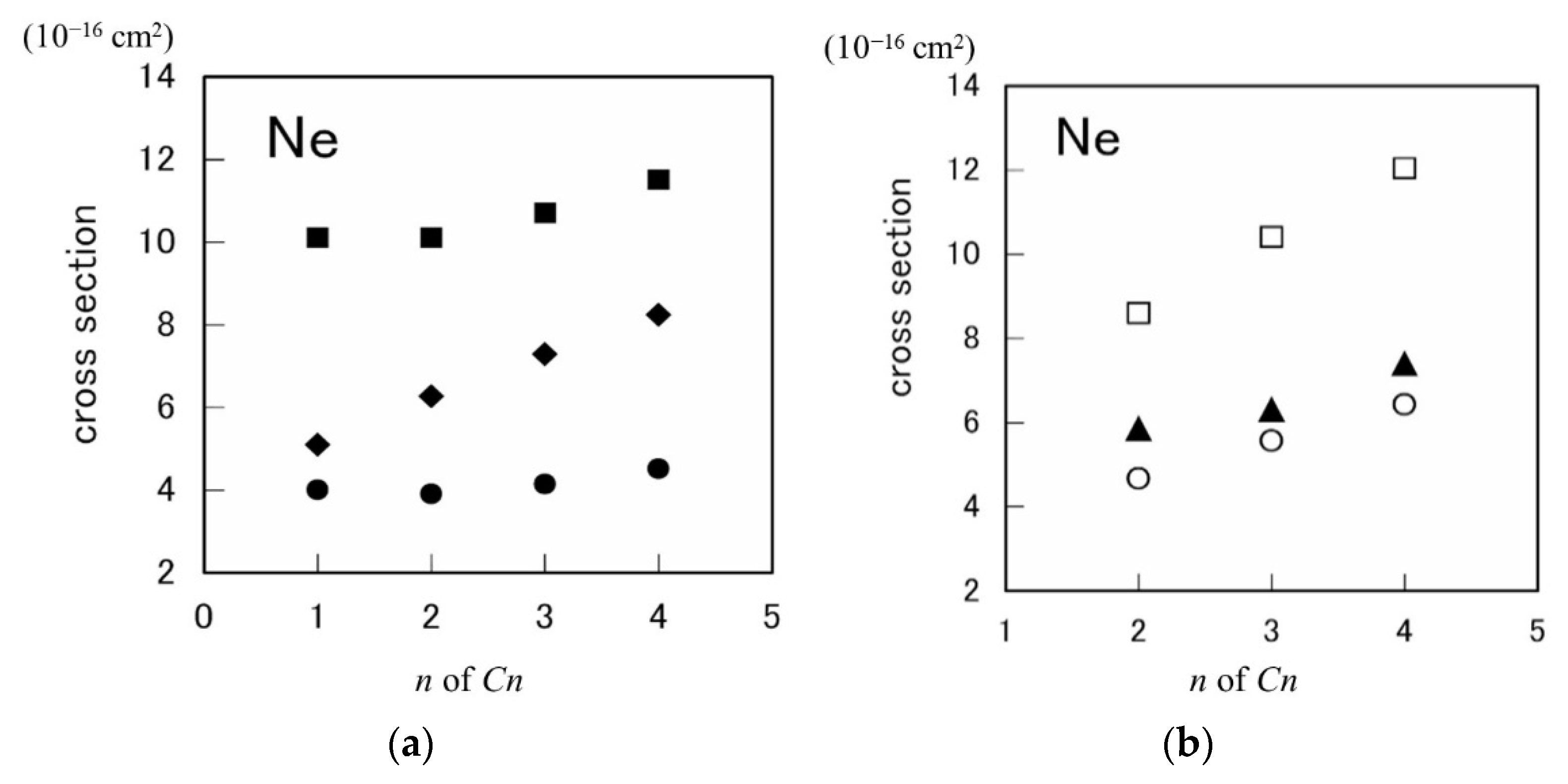
Figure 2 shows the electron-loss cross sections and the destruction cross sections , calculated for the 1.2 MeV/atom () (n = 2–4) clusters in a linear chain structure, colliding with Ne atoms. These cross sections are obtained by averaging over the cluster-orientation angle. For reference, we added the plot for the one electron loss cross sections calculated for a single carbon atom. These cross sections show the sub-linear dependence on the number of constituent atoms in a cluster. Namely, if we denote the cross section for a cluster by as a representative, these six cross sections are approximated by a linear relation as
Here, is the relative increasing rate per atom. If holds, this relation indicates the sub-linear dependence of the cross section on the atom number. In practice, we obtained in and in using Ne gas. In the case of in collision with a Ne atom, and are the same magnitude of those for a ion. The same calculation was performed for He gas and this sub-linear tendency holds valid too [38]. Sanders et al. [41] reported the one electron loss cross section of a carbon atom, colliding at with a He atom, is cm2. Judging from the error bar, our result shows a slightly greater value but is in agreement. Regarding the destruction cross section, Zappa et al. [42] reported data for a () cluster ion colliding at speed of with He and Ne gases. The values of data are nearly constant in the order of 10−15 cm2 irrespective of speed, the magnitude of which is in the same order as in our case. On the other hand, Mezdari et al. [43] reported a single ionization cross section for a () cluster ion colliding at speed with a He gas, the values of which are cm for , respectively. These values are close to our result, though ion speed is a bit higher.
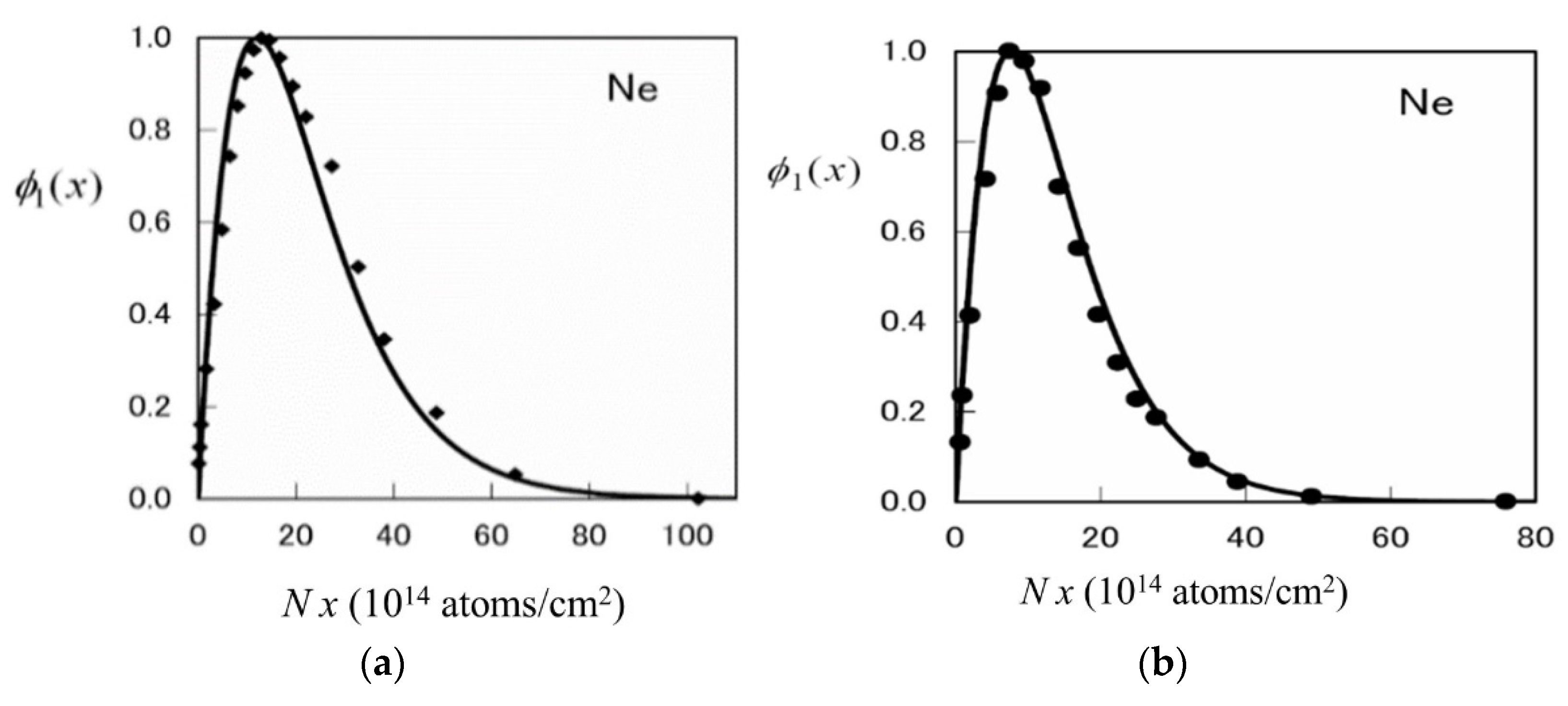
Using these six cross sections, we obtained the singly charged fraction of () in case where He and Ne gases are used as a charge-changing gases. In order to compare the results, the calculated values of are displayed together with the data obtained at TIARA for the 2.5 MeV and clusters using Ne gas. The experimental data were obtained as relative values so that, in order to compare quantitatively, the calculated values and the experimental data are both normalized at the maximum value, as shown in Figure 3. It is noticed that the speeds of the 2.5 MeV and are 2.04 and 1.443 , respectively. From the figures, the normalized curves are in good agreement with the TIARA data in structure, except a small difference (within atoms/cm2) in the gas pressure at which the yield reaches maximum. We also performed a similar calculation on the charge fraction of in ring structure with use of He and Ne gases [44]. Compared with in linear chain structure, the normalized charge fractions show a small amount of structure dependence. It is noted that both the experimental data and the theoretical curves seem to be described by a very simple formula such as , and so far this simple treatment was sometimes adopted. In this case, however, the physical meaning of the parameters is not simple, and it is difficult to correspond these experimental data to the theoretical cross sections, except for the decay cross section, which can be obtained from the asymptotic value of the charged fraction data. This is the reason why we started with the basic rate equation and included six cross sections. If one wants to obtain the charge state fraction of doubly positive cluster ions, the calculation method becomes more complicated (see Appendix A). Because four more (in total, ten) cross sections have to be estimated. This is a future problem.
3. Model for Electronic Stopping Power and Related Quantities
In the previous section, we presented the subtraction of swift cluster ion beams using a tandem accelerator. This section is devoted to presenting the interaction of a cluster ion beam with materials. One of important and basic topics is the energy loss of moving ions inside a material via electron excitation process, where electric charges of moving ions play an essential role in coulomb interaction. Swift cluster ions moving in a material at a speed over the Bohr speed tend to have a positive charge and explode with each other (so-called coulomb explosion). In general, these charges of constituent ions in a cluster are a bit fluctuating via electron capture and loss processes, and passing through a given distance, the charged fraction of ions attains an equilibrium state, where the average value of charged fraction, i.e., the average charge, is dependent of the ion speed. For a cluster ion, similar physical processes will occur for a single ion. We assume each ion in a cluster has an average charge depending not only on speed but also on neighbor ions. Thus, first we have to treat the average charge theory for a cluster ion, and after that, the electron excitation by a moving cluster ion will be formulated.
3.1. Cluster Average Charge
Compiled data on the average charge show that the average charge of single ions will tend to depend on ion speed in matter and roughly speaking not to depend on target materials [6]. In this respect, most average charge theories are based on the statistical model. The resultant formulae are summarized as the relative average charge vs. the reduced ion speed , where and denote atomic number and speed of an ion, respectively. In case of cluster ion incidence, on the other hand, this simple picture is found to be invalid [13,14,15,16,17]. In general, the average charge of constituent ions of a cluster ion emerging from a foil presents the following features: (1) the average charge value is less than that for a single ion with equivalent speed, (2) with increasing thickness of penetrating foil the average charge value is approaching that of a single ion with equivalent speed, and (3) the reduction of cluster average charge increases with the size of a cluster, i.e., with increasing the number of constituent atoms. We call this effect the cluster effect in the average charge. It is noticed that this reduction effect occurs inside a material, not on the out-going surface, and then affects energy loss of a moving cluster ions in matter. In order to explain this effect, we proposed the fluid-mechanical model theory based on the statistical model, which can predict the average charge of not only a single ion but also a cluster ion on the same theoretical background [14].
First, let us consider the electron stripping from a single atom. If we denote by the velocity of an electron bound on the atom, and by the ion velocity, the relative velocity of the electron at the rest frame of the ion is so that the fluid-mechanical model says that the electron excitation occurs when the energy condition of is fulfilled. Here, denotes the activation energy. The velocity distribution function of the bound electrons in a single neutral atom with atomic number is determined by the maximum entropy theory under the conservation of the total number of electrons and the total kinetic energy. As a result, we have
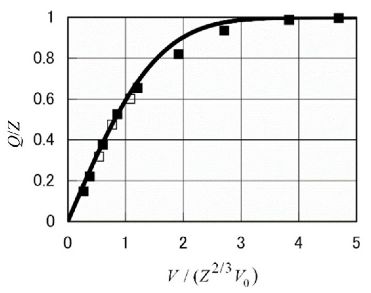
Using Thomas–Fermi–Moliere electron distribution in real space, we obtain , which connects with the average binding energy per electron, . Moreover, if we set for a neutral atom, the relative average charge is expressed in the following form:
The formula including the activation energy is also presented [14]. Figure 4 shows the calculated value of the average charge of single-atom ions as a function of the reduced speed. It displays a good agreement with the experimental data.
As for cluster incidence, the above expression is modified by taking into account the modification of the binding velocity . For the active electron (i.e., ionized electron) in the host positive ion, the existence of positive ions surrounding the host ion enhances the binding energy of the active electron, which results in increase of value. An example is seen between a hydrogen and a molecules. The ground state energy of the former is −13.6 eV and that of the latter is −28 eV. This is due to the participation of one more proton in electron binding. As a consequence of including the effect of surrounding ions, the increase of the binding energy per electron on the -th ion with atomic number allows us to replace in the simplest form by
where is the average charge of the -th ion and denotes the relative separation between -th and -th ion in units of . Here we assume the point charge model to describe each ion for simplicity. Then, the average charge of the -th ion, , is given by the equation
We remark that depends on the average charges of the other ions so that they have to be determined self-consistently. In addition, if the relative separations due to the mutual repulsive coulomb force evolves to be large enough, the term relating to the surrounding ions in Equation (12) vanishes and resultantly reduces to . Thus, the cluster average charge depends not only on the speed of ions but also on the spatial structure of the cluster. As an additional result, atom position in the cluster tends to clarified. Namely, the average charge of the centered ion in a linear chain structure is smaller than those of the atoms at the end positions since the binding effect acting on the centered atom is stronger. Examples of the present results will be seen later.
3.2. Electronic Stopping for a Cluster Ion
The energy loss of swift cluster ions penetrating a material was governed by the excitation process of target electrons. Especially in solid materials, electrons are classified by core (or inner shell) and conduction electrons. The dielectric function formalism has been used for estimating the electronic stopping power of an electron gas for a single ion [45]. We employed the dielectric function formalism in an extended way for a cluster ion, where using the dynamical dielectric function , the electronic stopping power is expressed as
In the above equation, and are momentum transfer and energy transfer to a target electron, respectively, and is the ion velocity. means the imaginary part of complex variable . denotes the Fourier transform of the cluster charge density in real space, . and denote, respectively, the atomic number and the position vector of the j-th ion in the center-of-mass frame of the cluster moving with velocity . In addition, is the electron density attached to the j-th moving ion, which is here described by the Thomas–Fermi–Moliere statistical distribution function. We assume that the electron density is given by the overlap of partially stripped ions, which have the average number of bound electrons, determined by the average charge theory. In principle, this stopping formula includes the individual position vectors of constituent ions. It is not attainable yet, however, to control the cluster orientation. Then, we assume the cluster orientation is random and take an average over the cluster orientation angle. Then, we have
with . The form factor , which is the Fourier transform of described by Thomas–Fermi–Moliere type spatial distribution for an ion with atomic number and electrons, is given by the following form
with and . The screening length is given by , where and is the average charge, determined from the average charge formula in Equation (13). Up to here, we obtain
This expression for a cluster ion with keeping the frozen spatial structure and electronic distribution in random orientation, holds sound in the adiabatic case where the speed of internal motion (i.e., coulomb explosion) is slow enough compared with the speed of the center-of-mass motion of the cluster.
3.3. Dielectric Functions
We employed two types of the dielectric functions. One is the Lindhard dielectric function [45], which describes the excitation of the conduction electrons in the electron gas model with the Fermi–Dirac distribution function at zero temperature, and another is the wave-packet dielectric function [46,47,48], which was developed to describe the excitation of the core electrons by the Gaussian distribution function. In this model, partial electronic stopping power per atom is estimated to the contribution of each electronic shell characterized by principal and angular-momentum quantum numbers. Therefore, total electronic stopping power per atom is given by the summing up the core-shell contributions for a gas target, and for a solid target the conduction electron contribution replaces the corresponding outer-core contribution. Regarding the excitation of conduction electrons, the dielectric function is expressed by Lindhard as a function of and instead of and as
with . A typical parameter in this theory is the -value, which is defined by the number density of conduction electrons as
which means the radius of a sphere occupied by one conduction electron in units of .
For metallic materials, we have , e.g., for carbon, for aluminum, for gold and silver. The -value is connected with the Fermi wave number and the bulk plasmon frequency as
The dielectric function should satisfy the sum rules:
As for the wave-packet model [46], the electric function is expressed in a similar form as a function of and instead of and as
In the above equations, and , where denotes a degenerate hypergeometric function. The function is also expressed as an integral [49]. The parameter is the orbital parameter classified by a set of the principal quantum number and angular momentum quantum number, () and determined as
from the momentum distribution function at the origin, , which is calculated from tables of Roothaan–Hartree–Fock wavefunctions [39,46]. is the number of equivalent electrons on the shell per atom. The calculated values of are tabulated for target atoms from He to U [46]. As a summary, we need two quantities and to use the one-shell dielectric function in the wave packet theory. The electronic stopping cross sections of solid and atom targets for a proton are also listed [46]. It is noted that in Equations (18)–(20), the original expression of the dielectric function in space is adopted. In Equations (24)–(26), however, we consider the correspondence of variables, i.e., instead of , and instead of . Therefore, the order of variable in the dielectric function produces no essential difference.
This equation corresponds to one of the sum rules if we replace in Equation (23) by . It is noted that and , where is the number of atoms per unit volume.
In this sense, two sum rules are the same if we regard the number density of equivalent core electrons per atom as the number density of conduction electrons per atom. Recently, the wave-packet model was extended [49,50] by introducing the binding energy of inner shells into via substitution of . This extended model was reported to give the inner-shell ionization cross section by protons even at lower impact energies.
3.4. Polarization Force
Up to here, we discussed the electronic stopping power by taking into account the cluster structure and assuming the coulomb explosion adiabatical. In order to include the electronic polarization force acting on individual ions, in this subsection we express the polarization force, induced by impinging cluster ions. Here we also assume the coulomb explosion acts adiabatically among constituent partially stripped ions (PSIs). Let us find the polarization force acting on the j-th PSI moving at velocity in a dielectric media. The charge distribution of the PSI is given by , where denotes the spatial distribution of bound electrons on the j-th ion. Using the induced scalar potential , the polarization force on the j-th ion is
Using the dielectric function of the media, this expression is rewritten as follows:
where . We decompose the above force in the perpendicular component and in the parallel one as follows [22]:
with In the above, is the -th order Bessel functions of the first kind, and () is the unit vector of the perpendicular (parallel) component of . In addition, and denote, respectively, the real part and the imaginary part of a complex variable , and () is the magnitude of the perpendicular (parallel) component of . We remark that the above expressions of the force consist of two types. One type is the conservative force, which is the term including the real part of the dielectric function, satisfying the action-reaction law. The other type is the dissipative (friction) force, which is the term consisting of the imaginary part of the dielectric function and absorbing the energy from impinging ions.
Another force is the repulsive coulomb force acting among constituent ions. This is obtained from the gradient of the potential energy. We write the force acting on the j-th partially stripped ion from other partially stripped ions as follows
Here, () is the charge density of -th (j-th) ion at position () from the ion nucleus at position vector (). In a dielectric media, this force reduces to a screened coulomb force if it is combined with the polarization force, which is brought from the real part of the dielectric function.
It is of interest to average the force over the cluster orientation when the cluster orientation is assumed random. The orientation average is to average the factors, including and , over the angle with keeping constant. This procedure leads to
Therefore, by summing up the force acting on every ion with orientation average, we obtained a familiar expression of the electronic stopping force acting on a whole cluster as
with . Thus, the sum of the z-component forces reduces to the conventional expression of the electronic stopping force for a cluster ion with random orientation. The perpendicular force for a cluster resultantly vanishes since the orientation average means the axial symmetry with respect to z axis.
3.5. Coulomb Explosion of Constituent Ions
Apart from single ion incidence, the internal force, i.e., repulsive coulomb force, works among constituent (or fragment) ions. This is due to the phenomenon that the electron-loss process surpasses electron capture process, which makes the charge state of each ion higher. Thus, the internal force expands relative distances between ions moving in material. Therefore, in order to obtain the total energy loss of constituent ions after penetration of a foil, one has to pile up the energy losses in each sliced thin layer, where the coulomb explosion force and the resultant expansion of inter-nuclear separation are taken into account. To do so, we need to know the time evolution of the inter-nuclear separation due to coulomb repulsive force. Regarding two ions with mass and charge (), the time evolution of the inter-nuclear distance is governed by the following equation-of-motion
The solution of this differential equation is solved with initial separation at . We obtain the expression described in the reduced form
Here, the reduced separation and the reduced time are defined as , with . This expression was extended to highly symmetric clusters such as ring structures. Regarding the clusters composed of homo atoms in the 2D ring structures, because of having equal average charge and equal mass , the characteristic time is given by
By direct substitution, for example, we obtain = 2, 3, for , respectively.
4. Calculated Results on Penetration of Cluster Ions
The noticed quantity for the impact of a homo-atom cluster , e.g., the average charge and the energy loss , etc., is usually characterized by the following two values:
where is the corresponding quantity for a C ion at equivalent speed. The former is the relative difference per atom and the latter is the ratio per atom. The positive (negative) cluster effect corresponds to () or (). We show that between these two aspects, there exists the threshold value of the incident speed or kinetic energy under cluster impacts.
The results shown below are classified into two parts. One is on relatively small clusters and the other is on a fullerene.
4.1. Average Charge and Energy Loss of Cluster Ions
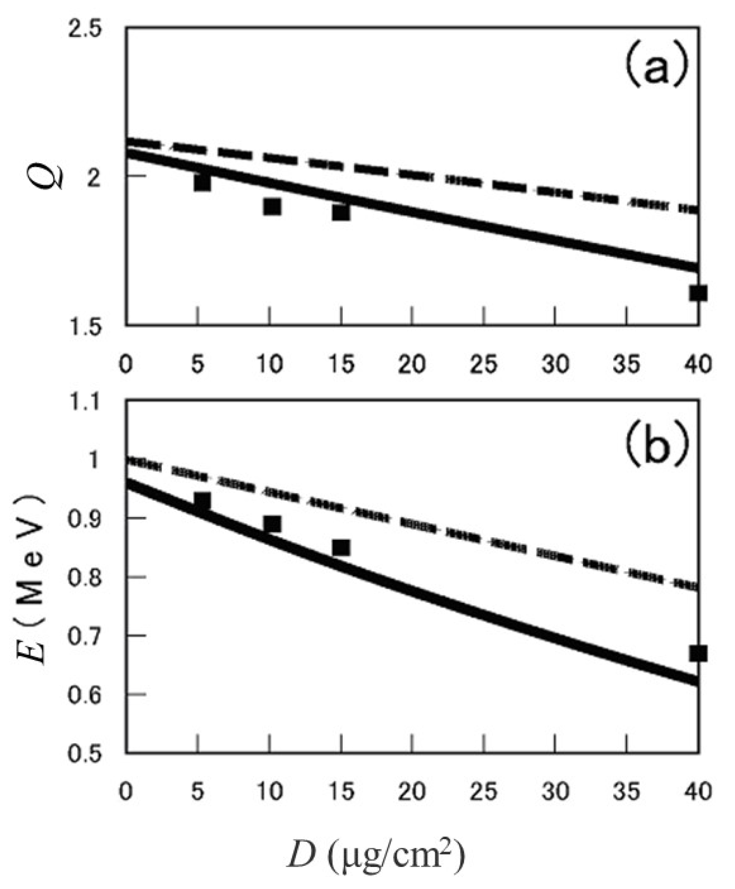
In order to check the calculation algorithm, we first show the average charge and the kinetic energy are calculated for a carbon ion as a function of foil thickness . Figure 5 shows (a) the average charge and (b) the kinetic energy , where the solid line refers to the results of 0.96 MeV C ion incident on carbon foil together with the experimental data [51], and the broken lines does to the results of 1 MeV C ion incident on aluminum foil [15]. In these calculations, first, the speed-dependent average charge was determined and second, the energy loss was determined by integrating the stopping power in thin layer that includes this average charge. The theoretical curves are obtained by repeating this calculation cycle.
Regarding a cluster-ion incidence, the calculation scenario was slightly changed. (1) The foil is divided into thin computational layers. The constituent ion/atom positions and their speed are input first. (2) In a layer, average charges of constituent ions in a cluster are determined for given ion positions by taking into account the cluster speed. Using the stopping power and the coulomb explosion force, the degraded speed and the expanded spatial positions of constituent ions are both determined. (3) Move to next layer and repeat calculation carried out in the previous layer.
Comparison with Experimental Data
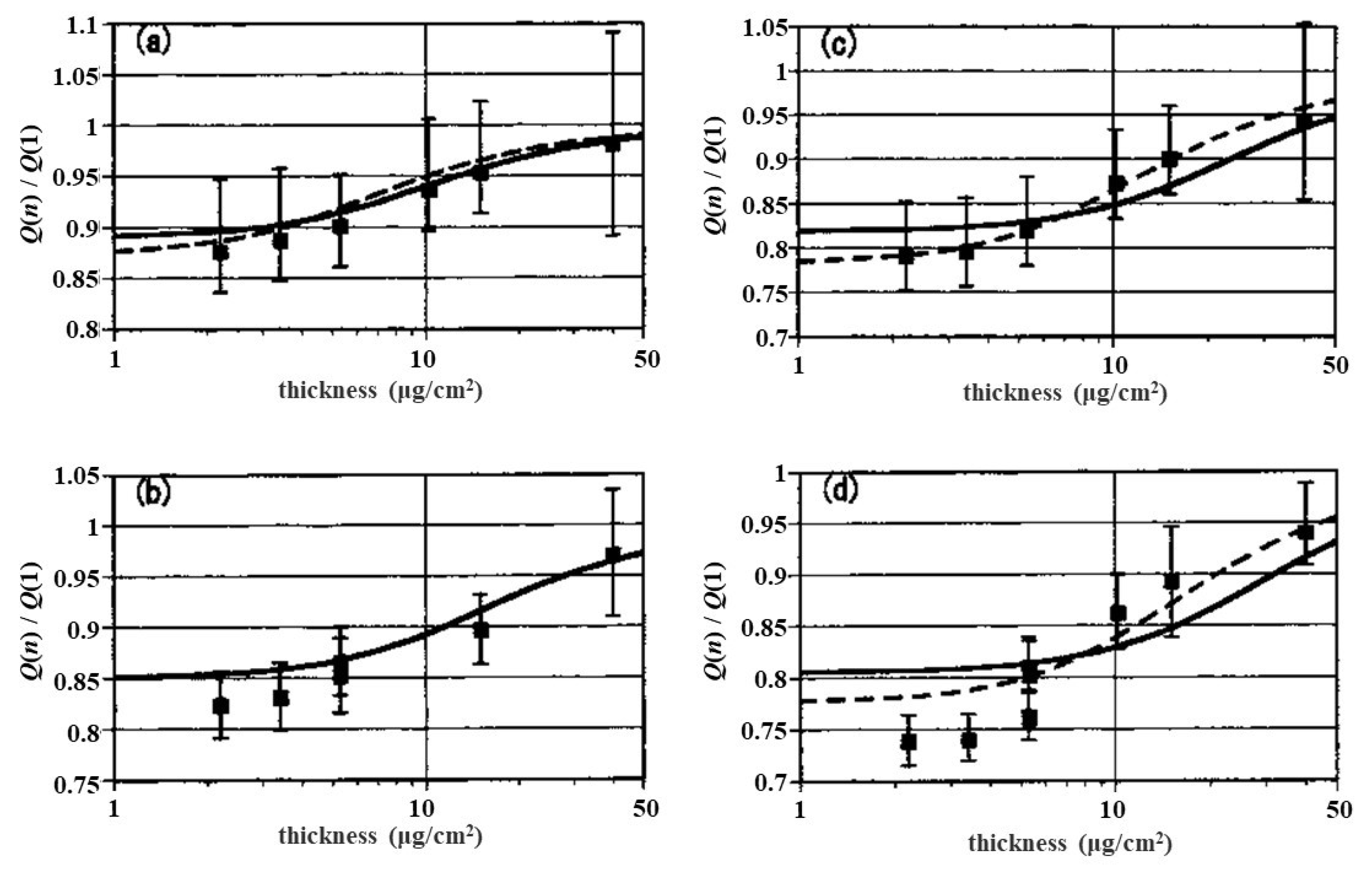
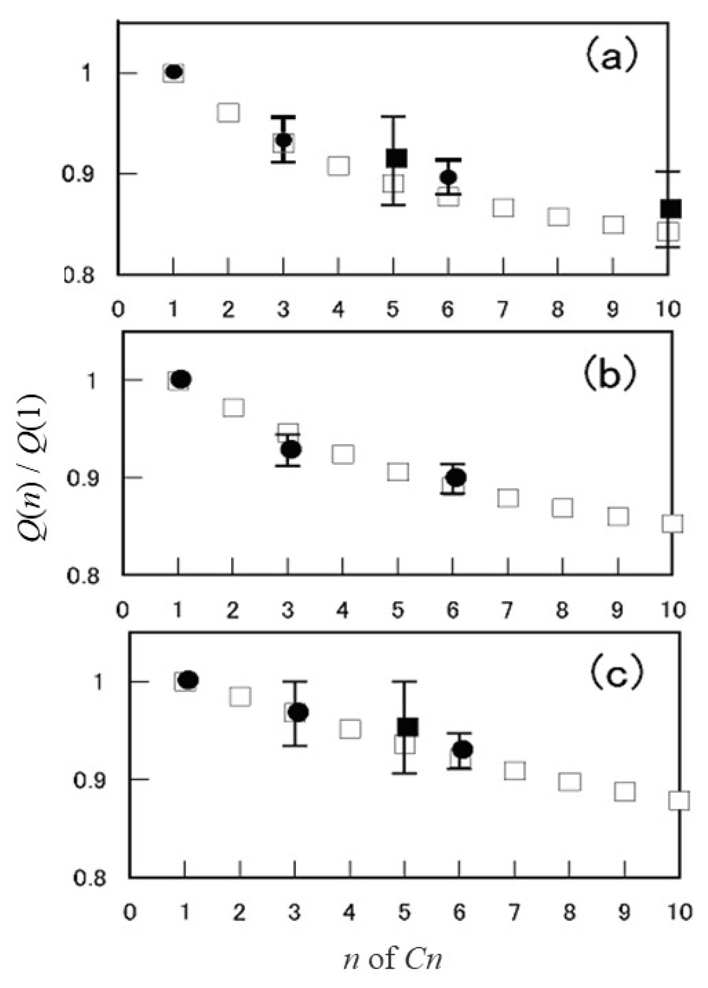
The first prominent data on the reduction effect in the cluster average charge per fragment ion were obtained by Brunelle et al. [13] for a ion with kinetic energy of 2 MeV/atom, emerging from carbon foils, shown in Figure 6. Their data show that (1) is smaller than for a single carbon ion with equivalent kinetic energy, (2) reduction rate of is maximum in very thin foil and it increases with increasing foil thickness, and finally attains unity, and (3) reduction rate of increases with increasing the cluster size . These phenomena are explained by the present average charge theory in Equation (13) with inclusion of coulomb repulsion inside a target material. In Figure 6, the solid lines indicate the results for fragment ions of a ion in linear-chain structure. In addition, in cases of , the broken lines indicate the results in the ring structure. Compared with these theoretical curves, the ring structure tends to yield the lower average charge when emerging from very thin foils. Figure 7 shows the cluster size dependence of the average charge for 2 MeV/atom emerging from a carbon foil of 2.2 μg/cm2 thickness. It clearly shows a monotonous decrease with increasing the number of atoms [14]. Another important feature of this theory displays that the average charge of fragment ion originating from a linear chain cluster, differs in atom position belonging to the initial cluster ion, e.g., edge position or center position, as shown in Figure 8.
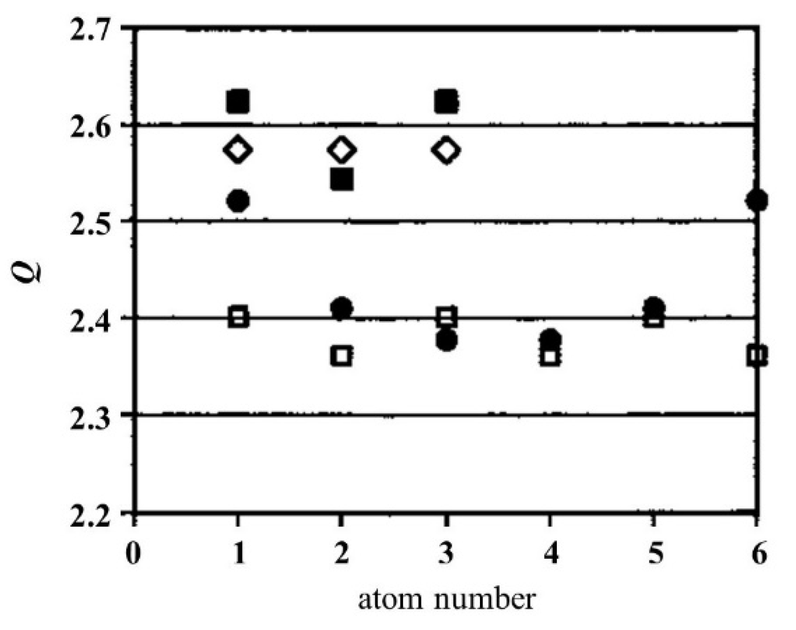
Figure 8 shows the atom-position dependence of the self-consistently calculated average charges of constituent ions in the cluster with the initial kinetic energy of 2 MeV/atom, penetrating the carbon foil of 2.39 μg/cm2 thickness. The symbols refer to the linear-chain structure (■) and the ring structure (◇) for , and the linear chain structure (●) and the ring structure (□) for , respectively. The atom position order is indicated by atom number. In linear chain structure, the middle atom position yields the lowest value, due to the largest binding effect. In ring structure, triangle structure of is assumed regular so the average charges of three ions are the same, while in the ring structure is not regular and two kinds of atom positions exist symmetrically so that two different values appear cyclically with atom position. These theoretical aspects were proven experimentally at TIARA Takasaki using the 1 MeV cluster ions passing through a carbon foil [16]. They used CCD camera to detect charge states and 2D position of three fragment ions, and to classify the original structure by deducing with the use of computer simulation results on coulomb explosion force. The experimental results are listed with the calculated results in Table 1, which clarified (1) the average charge in the ring structure is lower than that in linear chain structure and (2) the average charge of an ion in center position is lower than that in the edge position. These results also prove that charge changing process occurs inside a solid.
Making use of this method, we show in Figure 9 the cluster size dependence of the average charge calculated for 1 MeV/atom ions in linear chain structure incident on carbon foils of (a) 5 μg/cm2 (b) 8 μg/cm2 (c) 15 μg/cm2 (□). The experimental data obtained by (■ [13]) and by Chiba et al. (● [52]) are in good agreement with the calculated result. These figures indicate the average charge ratio decreases monotonously with increasing cluster size. A similar figure was also obtained for a carbon cluster ion moving in aluminum foil, as shown in Figure 10. Compared with the carbon foil case, characteristic features look similar but the thickness dependence of the average charge varied a bit, since it was brought via the degradation of the cluster speed due to material dependence of the electronic stopping power. The growing of the inter-atomic separations due to coulomb explosion is a main reason why reduction rate becomes smaller with increasing foil thickness. As a summary of this topic, the present method works well to predict the average charge and the energy loss in the thickness range displayed.
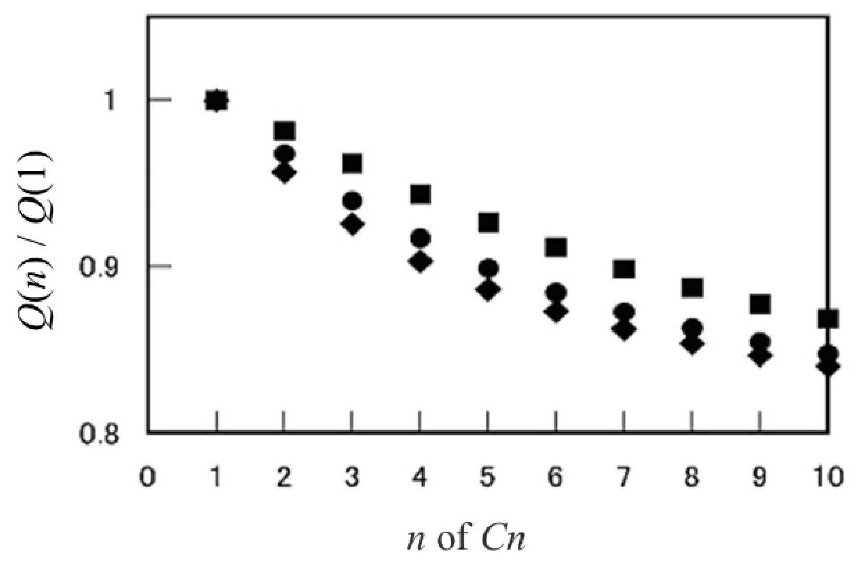
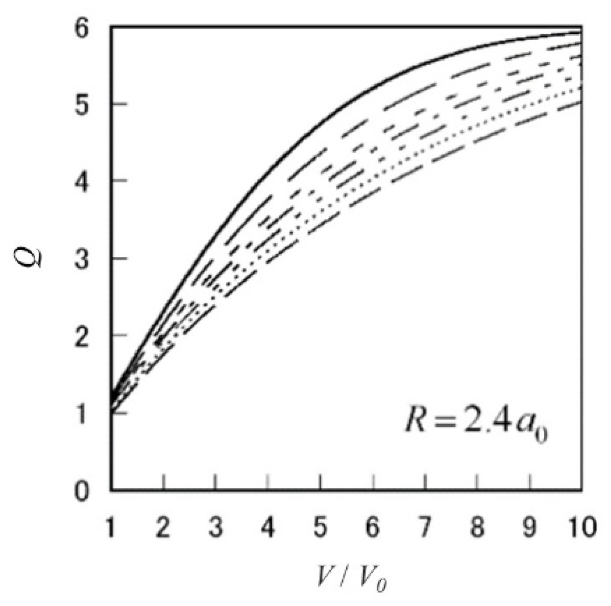
As a final part of this section, we show the average charge of carbon cluster ions in a wide range of speeds and cluster sizes. Figure 11 shows the speed dependence of the average charge for a ion in ring structure with inter-atomic separation of . As a general feature, one sees the average charge increases with increasing ion speed and decreases with increasing the number of atoms.
4.2. Energy Loss of Cluster Ions
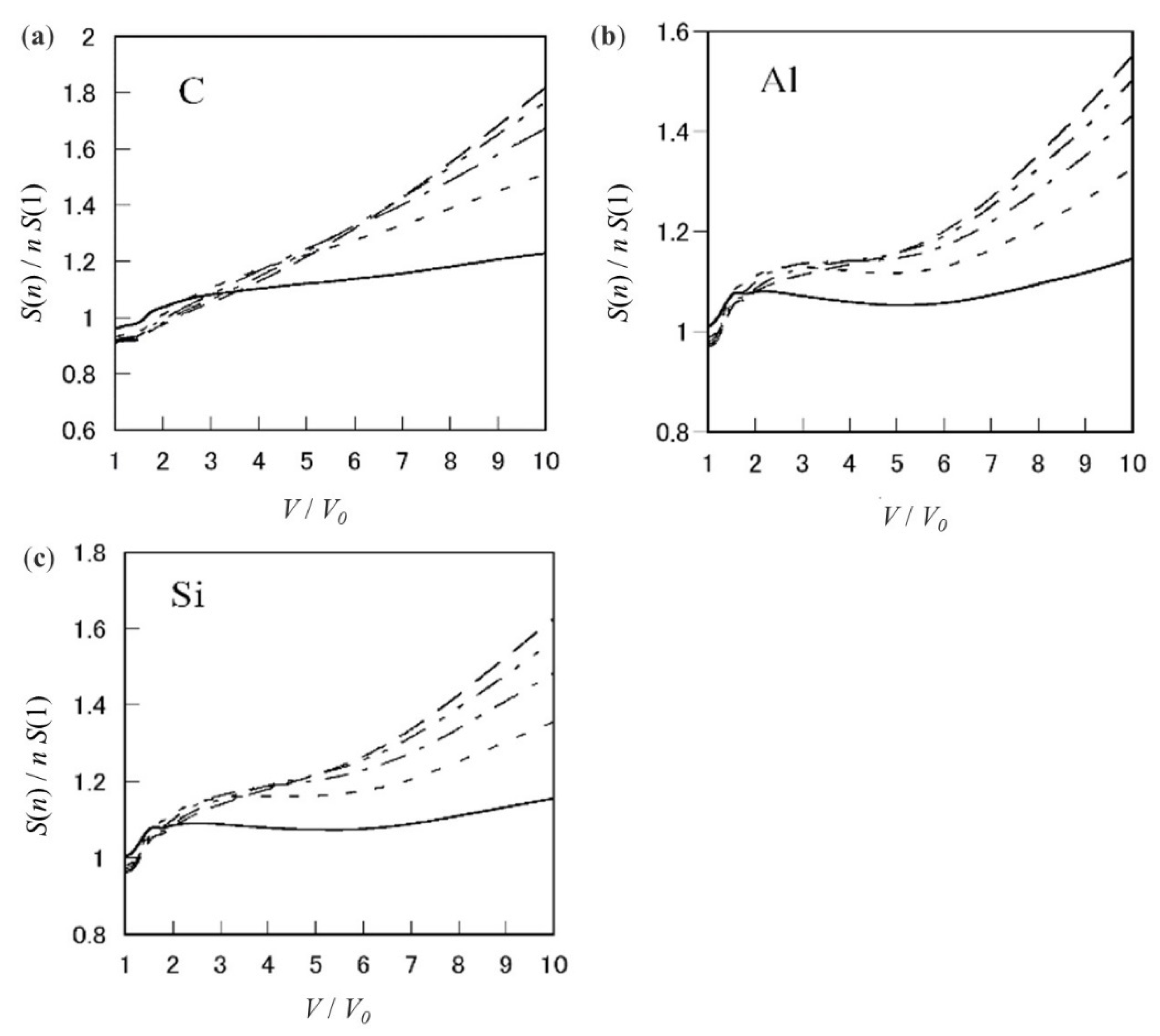
The energy loss of cluster ions is related to the average charge reduction, through which the energy loss per ion presents both positive and negative cluster effects. First, we show in Figure 12 the ratio of the stopping power per ion, , of carbon, aluminum, and silicon targets for a carbon cluster ion in linear chain structure with interatomic separation of at speed of , calculated using two types of the dielectric functions in the electron-gas model and the wave-packet model. Calculation scheme is, first, to estimate the average charge of constituent ions at a given speed. Next, using the average charge and the form factor, the stopping power for the cluster is calculated but the coulomb explosion effect is not taken into account. Then, the estimated values would correspond to the energy loss of the cluster ions in a thin layer around the incident surface since the initial inter-atomic separation is assumed. The values of parameters in individual electron shells of these targets needed in calculation are listed in reference [46]. In Figure 12, solid lines, short dashed lines, dot-dashed lines, dot-dot-dashed lines, and dashed lines refer to , and , respectively. These figures display that the stopping power per ion, , for a ion is found to be greater than that for a ion at equivalent speed of . Moreover, the ratio increases with increasing speed. The results corresponding to ring structures are also obtained for aluminum and silicon targets [21]. The super-linear dependence on the number of constituent ions is clearly appreciated for all targets listed here, except at low speed.
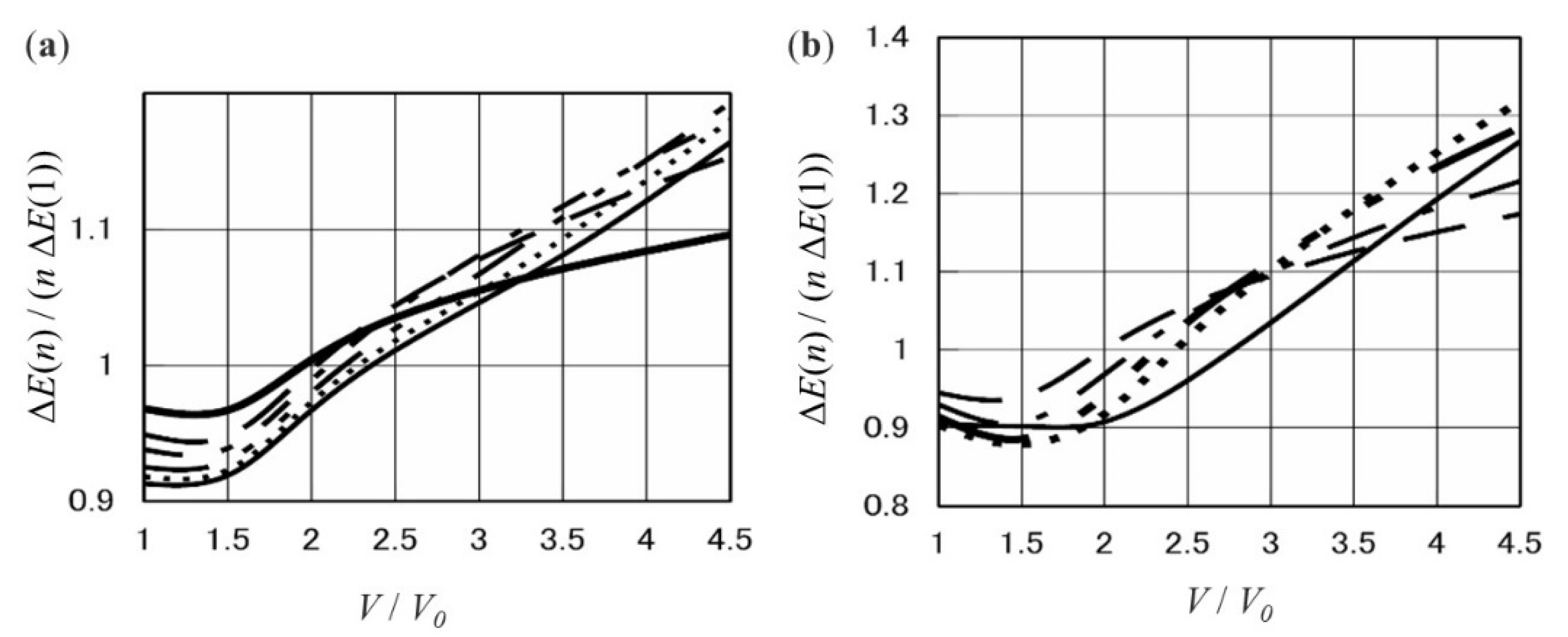
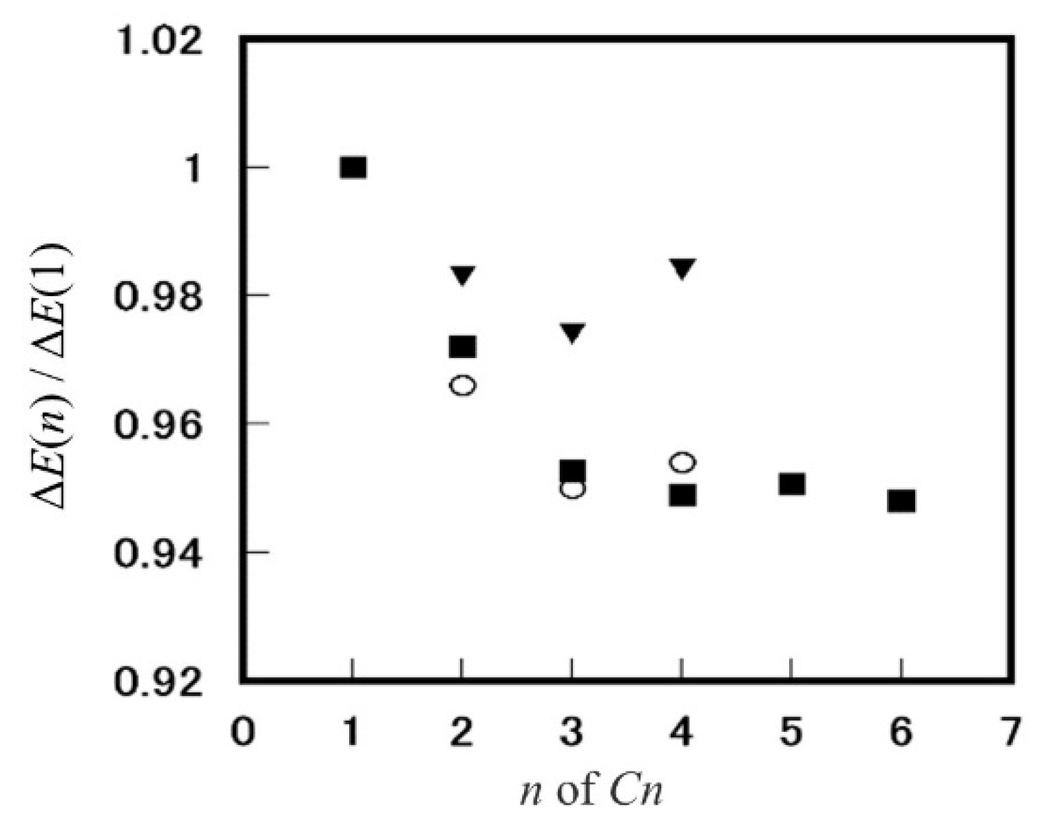
In Figure 12, we look over the calculated stopping-power ratio presents the cluster effect. In order to look in detail, we calculated the energy loss value for a cluster by taking into account the slowing down, the average charge, and the coulomb expansion making use of the Runge–Kutta method. The results are presented in Figure 13 for ions in linear chain structure and ring structure passing through a carbon target of thickness 26.5 nm at initial speed of [14]. We are able to see that the threshold speed, at which the energy loss ratio per ion yields unity, is located between 2 and 2.5 for a linear-chain structure, and between 2 and 2.8 for a ring structure, unity, though it depends on the cluster size. We realize two points: (1) Over the threshold, the ratio is larger than unity though the average charge ratio is reduced to be less than unity and (2) below the threshold, the energy loss ratio per atom is less than unity. These features originate mainly from the correction of constituent ions penetrating a target material. Moreover, the average charge reduction plays a significant role. In order to see the second point clearly, we present Figure 14, where inclusion of the average charge reduction works significantly (about five percent reduction) compared without inclusion (at best two percent reduction) [22].
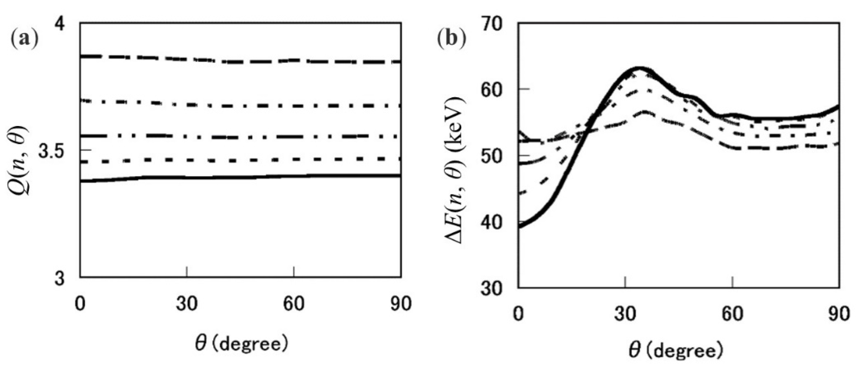
Up to here, we have presented the results on the energy loss or stopping power and the average charge taking into account the coulomb explosion. In a final part of this topic, we show the results including the electron polarization force. As described previously, this polarization force contains the conservative force and the friction force. The latter is characterized by the imaginary part of the dielectric function. As an example of high energy cases, Figure 15 shows the average charge and the energy loss of a linear-chained ion with kinetic energy of 4.8 MeV per atom, passing through a carbon foil of thickness as a function of the initial orientation angle [22]. At a glance, the average charge is almost constant with respect to for all cases, while the average energy loss per atom displays a strong -dependence. Especially for larger () clusters, the energy loss in the region of is suppressed compared to in the region of .
Regarding smaller cluster ions, the -dependence of the average energy loss looks weaker in the case of the high incident energy (4.8 MeV/atom). The features in average charge and the energy loss tend to vary at lower kinetic energy. As a typical case, we show in Figure 16 the individual energy loss of the leading ion (dashed line) and the trailing ion (dot-dashed line) for the 0.50 MeV/atom incident on carbon foil of thickness. The solid line shows the average energy loss per atom, which gradually increases with increasing the orientation angle . This example clearly displays the orientation dependence of the energy deposition, namely, the cluster in the perpendicular orientation (the cluster axis is perpendicular to the incident direction i.e., ) tends to deposit the energy more than that in the parallel orientation (the cluster axis is parallel to the incident direction, i.e., ). The difference in the energy loss of about 14 keV for becomes smaller with increasing and at last vanishes at [22].
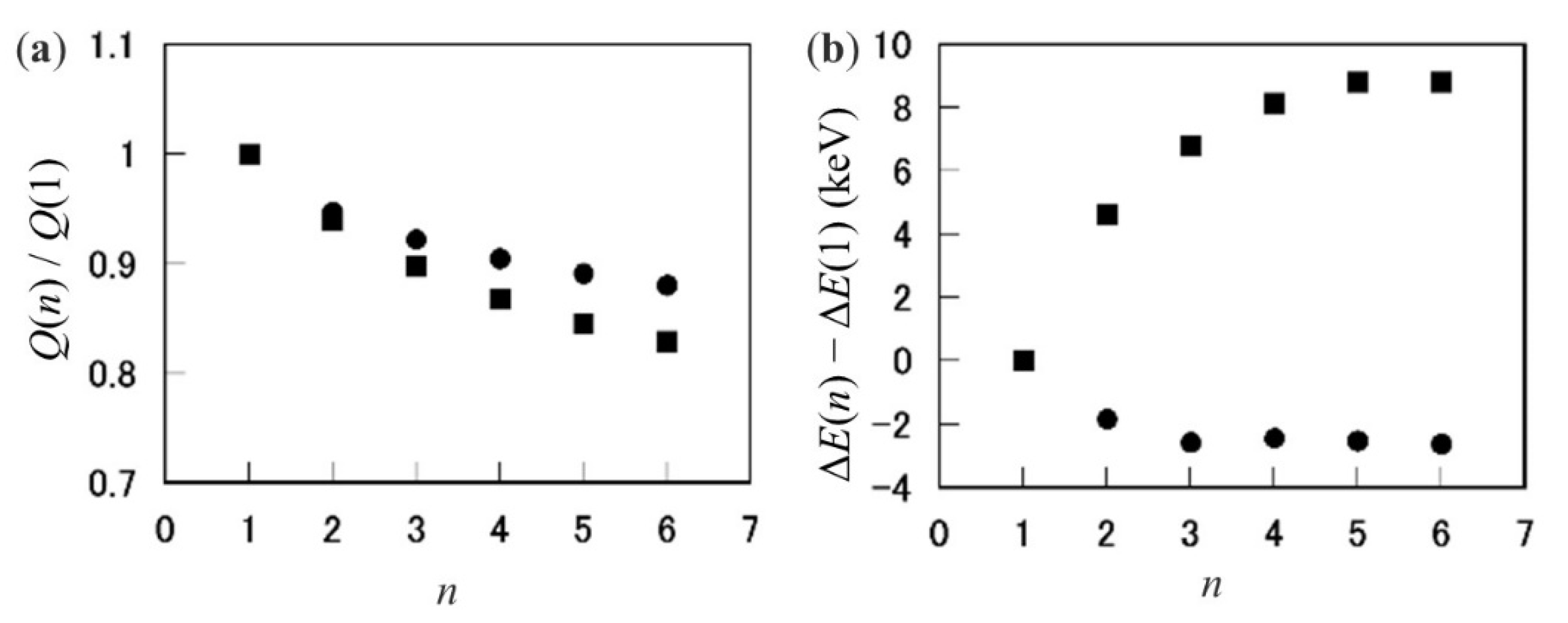
Figure 17 shows the cluster-size dependence of the energy loss and the average charge per atom of a carbon cluster at MeV/atom and at keV/atom. These energies are chosen as a representative of the incident energy over and under the threshold energy, respectively. One sees the energy loss difference per atom in high (low) energy case is positive (negative), though the average charge ratio shows a negative cluster behavior in both cases. This feature implies that the spatial correlation of constituent ions plays a dominant role in the energy loss of a cluster ion, that works positively at high energies, and negatively at low energies.
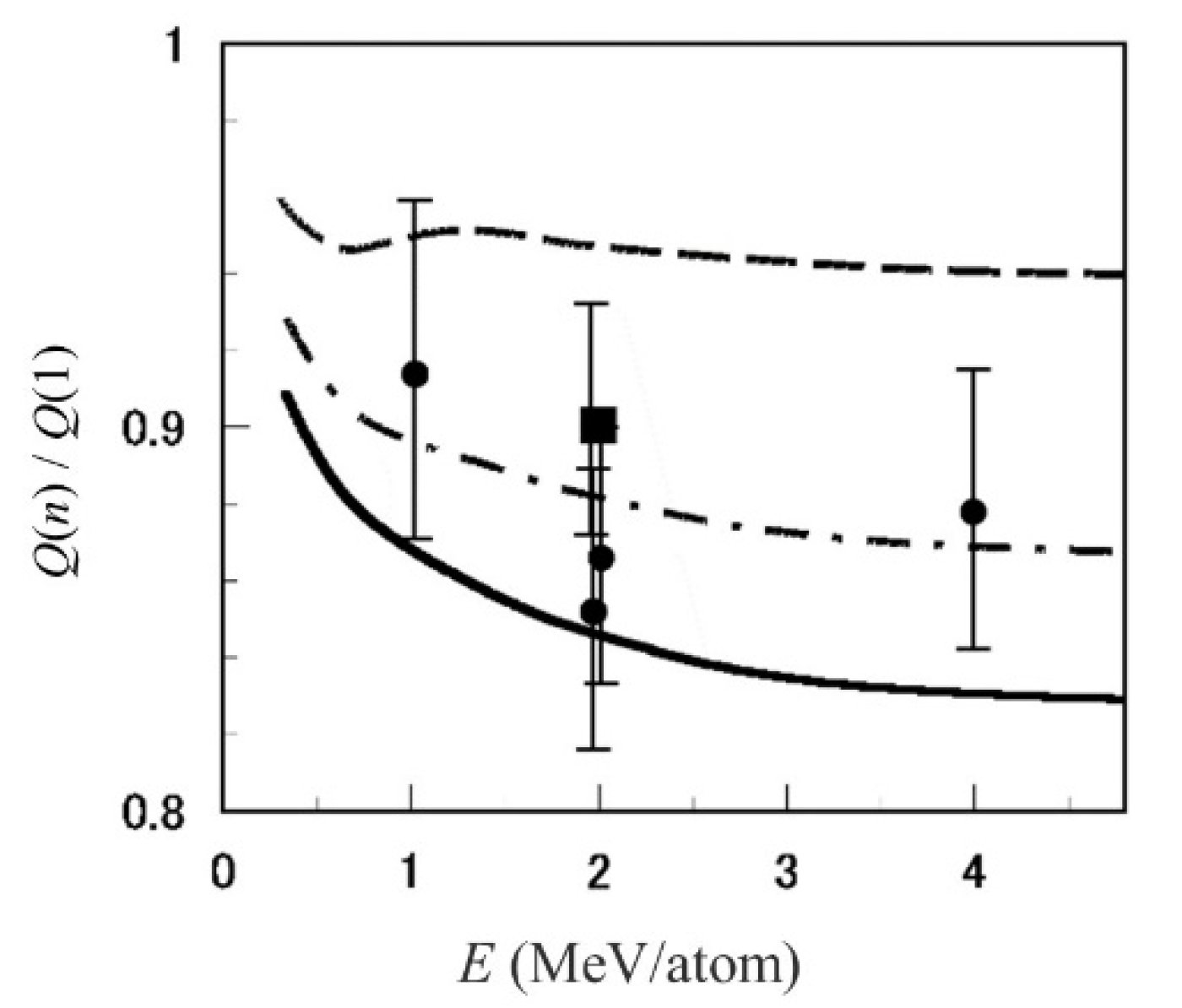
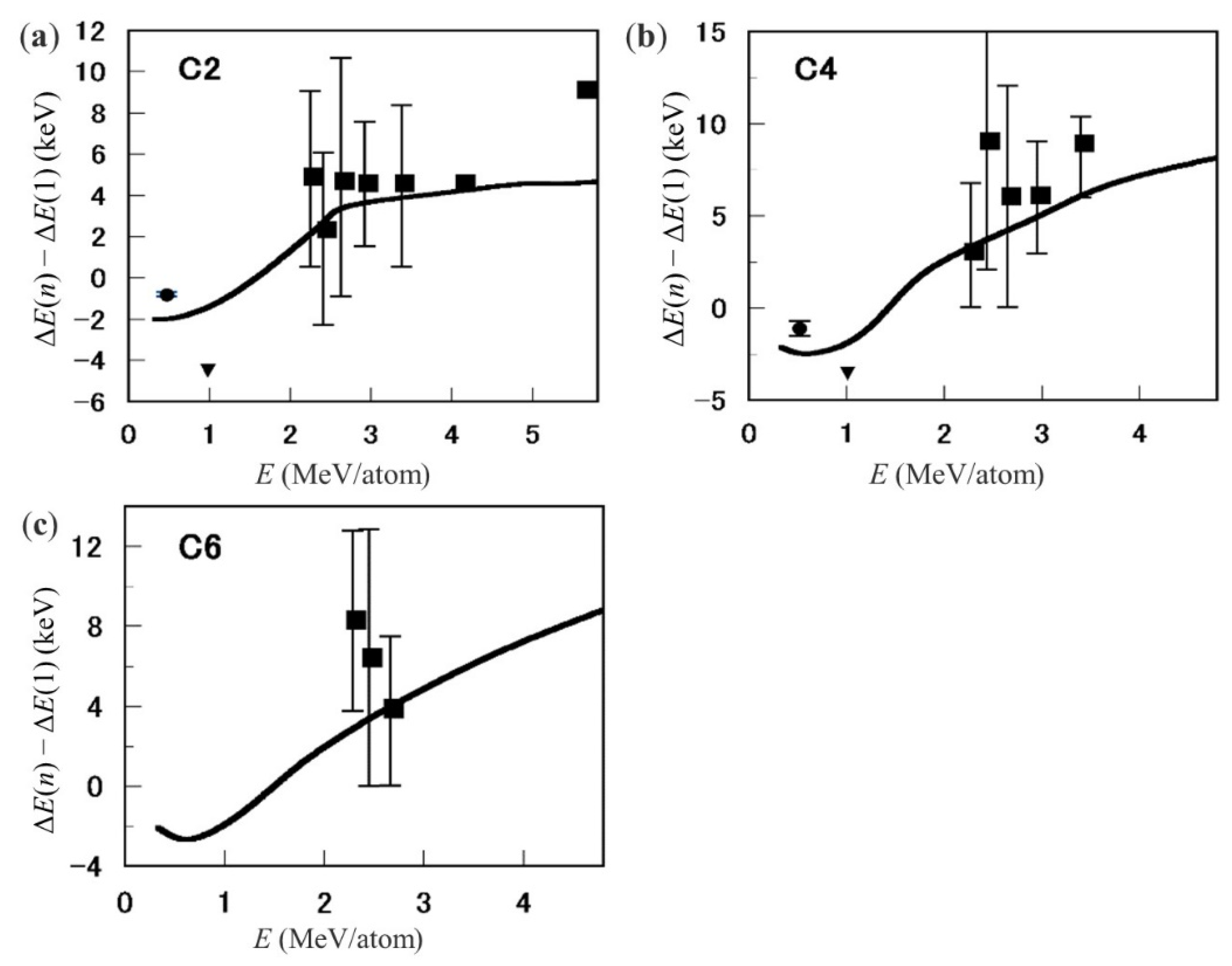
Figure 18 shows the energy dependence of the average charge ratio for cluster penetrating carbon foil of thickness together with the experimental data [13]. The calculated data reflect well the experimental ones though the error bars are a bit large [22]. Figure 19 shows the energy loss difference per ion of , , and cluster ions from that of a C ion at equivalent speed, penetrating carbon foil of thickness. These results are in quite good agreement with the experimental data. It is remarkable that the energy loss per atom difference at lower (less than 1.5 MeV/atom) incident energies display negative [23,51]. This is a sensitive problem but Tomita et al. [23] clearly showed the experimental results with very small error bars.
The present results in Figure 12, Figure 13, Figure 17b and Figure 19 imply the existence of the threshold energy (or speed) of incident cluster ion, which changes from negative to positive cluster effect in the energy loss. Finally, we add a report on the quantitative evaluation of cluster charge reduction [52], where the relationship was treated in detail between the charge state and the interatomic distance of the constituent ions of 6 MeV cluster ions traversing a carbon foil of 8 nm thickness.
4.3. Average Charge and Energy Loss of a Fullerene Ion
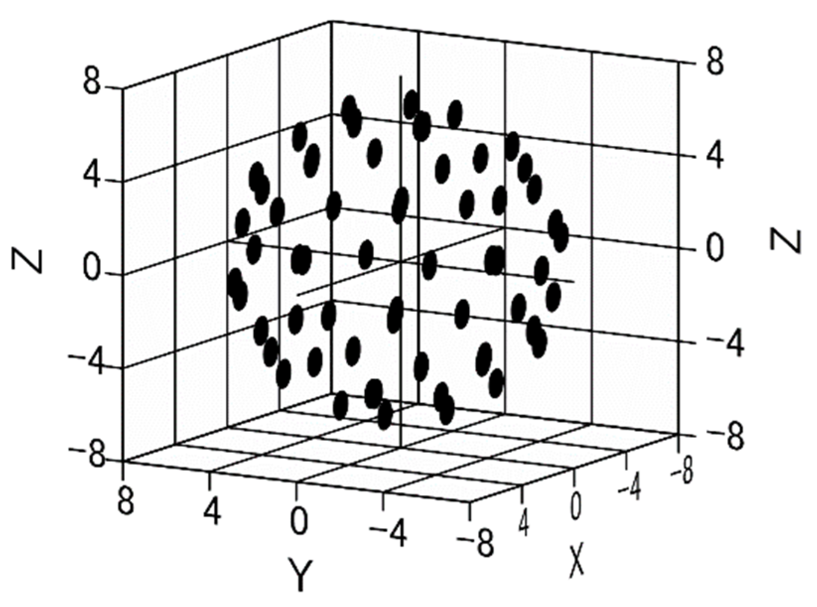
It is known that a C60 molecule has an icosahedral symmetry. A C60 molecule is a truncated icosahedron, including 60 carbon atoms. A C60 molecule has a peculiar structure called a ‘hollow atom’ in that 60 atoms are on the surface of a sphere of radius in the ground state structure. We assume here 60 isolated atoms are located on the positions of a truncated icosahedron and do not discern single and double bonds, because we regard a C60 as an ensemble of isolated homo-atoms. In general, the average charge per ion of swift carbon clusters with speed higher than the Bohr speed tends to be greater than unity and consequently the outer-shell electrons are almost stripped off. Then, we suppose that the molecular effect will play a negligible role. The spatial positions of 60 atoms are determined by considering symmetry on 5-fold axis, as shown in Figure 20.
First, in order to see the spatial correlation of atoms, we show the pair-distribution function in real space structure for a cluster composed of atoms located at , defined as
using the distribution in real space. The Fourier transform of is given by
where is the pair-correlation function in space as
If we take an average over the orientation of , we obtain
As another example to be compared, we take the angular average of atom distribution on a sphere of radius . Then, one obtains
and reduces to
It is instructive to show the structure factor of a C60 in Figure 21. The values of and at are both 3600, which corresponds to the square of the total number of atoms (). At very small k values, both quantities are very close to each other, while at k greater than 1 (a.u.), looks to smear out the fine structure of . This curve affects the magnitude of the electronic stopping power, especially contribution of the distant collision.
Next, we see the relation between pair correlation function and the charge distribution function of a superposition of partially stripped ions as . Then, the Fourier transform of and its square of absolute value are of the following forms:
The second term in the second equation corresponds to the pair correlation function if we replace the partially stripped charge by unity. In this sense, the second term of the charge density reflects the pair correlation. The first term of indicates that the sum of isolated charge squares, which implies no correlation in charge distribution. Later, we will see the super- and sub-linear cluster effect in the electronic stopping or energy-loss. This feature originates from the second term of . As mentioned, the average of the second term over the orientation angle yields the expression of Equation (15).
Average Charge of a CC60 Ion
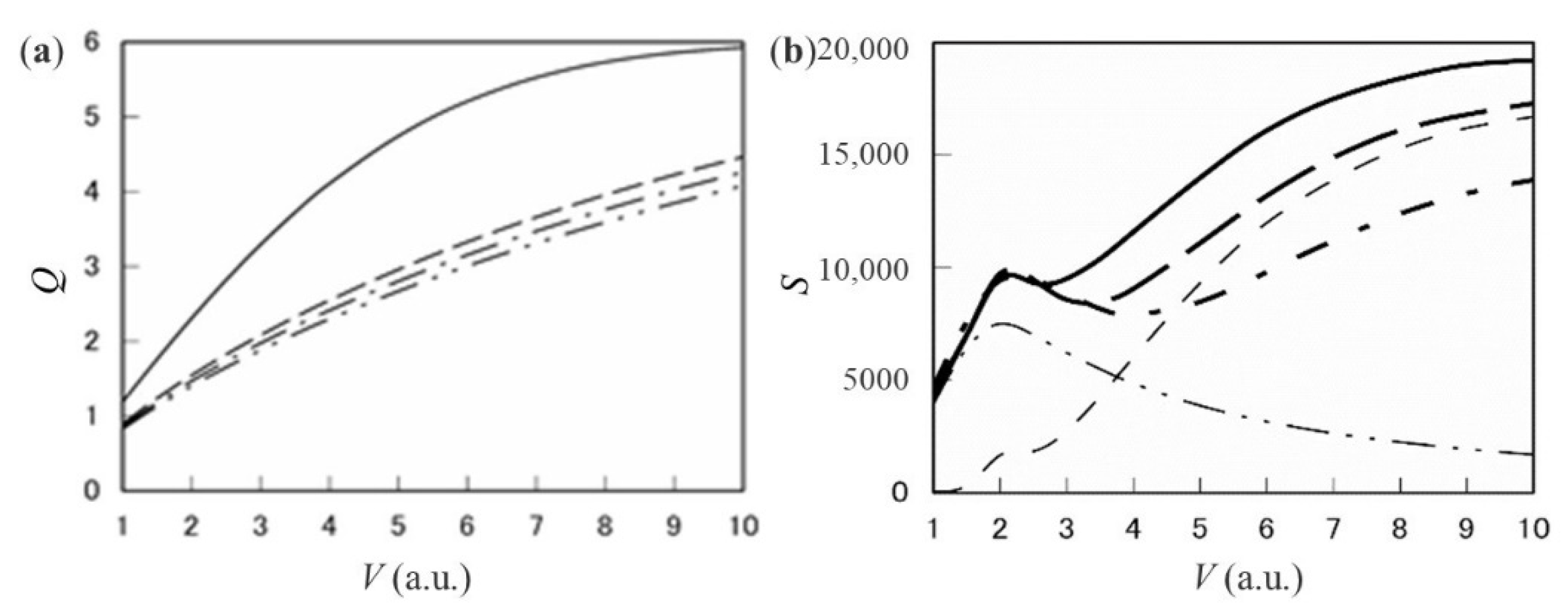
Figure 22 shows the average charge per atom,, of a CC60 at speed of v = 1–10v0. Assuming the expansion of a cage, three cases are shown in Figure 22 (left) for the initial cluster radius (dot-dot-dashed line), and two expanded radius (dot-dashed line) and (dashed line). The solid line shows the average charge of a single C ion. From this figure, one sees that (1) is about 60 percent magnitude of in the range of , and (2) does not vary so highly with increasing the radius. Regarding point (1), this reduction rate is much larger compared with those of small linear chain clusters. This is due to the fact that each atom has three nearest-neighbors and six second-nearest-neighbors.
Figure 22 shows the average charge per atom Q and the electronic stopping power S of carbon in units of eV cm2/atom for a C60 fullerene ion as a function of ion speed in unit of [53]. As for average charge, the dot-dot-dashed line, dot-dashed line, and dashed lines refer to a C60 with a fixed cluster radius of , , and , respectively, with reference of the single C ion (solid line). Regarding the electronic stopping, the solid line, the long dashed line, and the dot-dashed line refer to the case of a C60 with , , and , respectively. The dot-dot-dashed line and the short dashed line indicate the contribution of the single-electron excitation and that of the plasmon (collective) excitation in the case of , respectively. In the electronic stopping of carbon for a single ion, the peak value locates about at . Moreover, for a point charge intruder, the so-called equipartition rule holds valid so that the contribution of the single-electron excitation is equal to that of the collective excitation in the high-speed limit. This theorem was proved by Lindhard [45]. However, in the C60 case, the contribution of the collective excitation is found to rapidly grow and overcome the single-electron contribution with increasing speed. In addition, the collective contribution has a giant peak over the speed of . This proves that the sum rule does not hold valid for cluster ion intruders. The appearance of this effect originates from the collaboration of the reduction of average charge and the vicinage effect of collective charges. The effect of the latter part only was reported on hydrogen cluster ions. At present, however, as far as the author knows, there has been no report on a C60 ion. One reason is that the accelerated voltage is too high to accelerate a C60 molecule up to the kinetic energy 288 MeV using a tandem accelerator, corresponding to the speed .
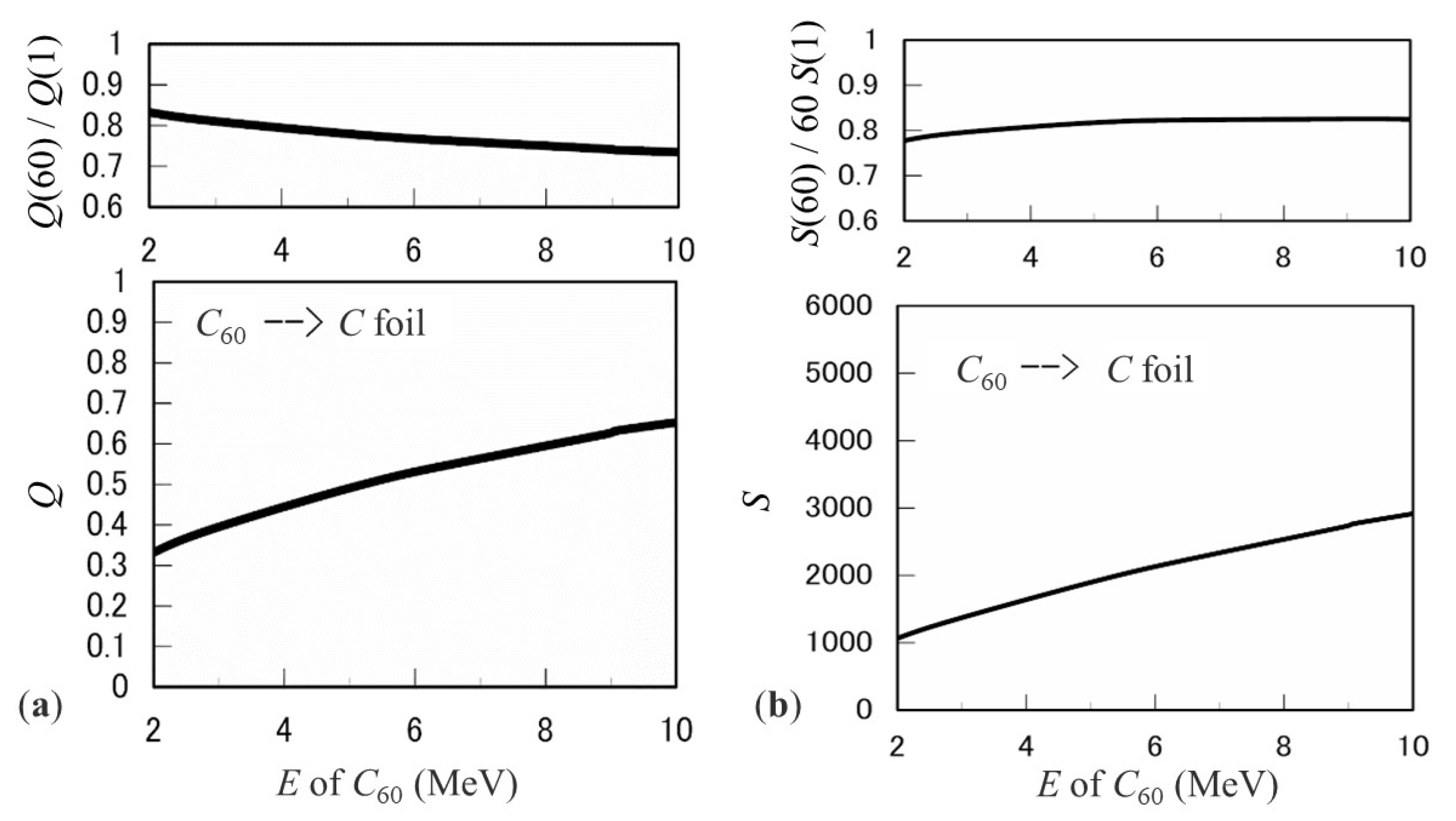
Next, we move to a lower energy case. Figure 23 shows the average charge per atom, , and the electronic stopping power for a C60 molecule at the kinetic energy of 2–10 MeV, together with ratios of those quantities to corresponding values of the single C ion at equivalent speed (). From this figure, both the average charge per atom and the electronic stopping power of carbon for a C60 are found to be roughly 80 percent in magnitude of the corresponding value of a single C ion in the energy range studied. This reduction rate of the electronic stopping may affect the stopping of other materials.
4.4. Relation between the Electronic Stopping Power and the Secondary Electron Yield
It is well known that the secondary electrons (SEs) are emitted from a material by swift ion impact. The emitted electrons are classified as the low energy electrons (the electron energy is roughly less than 50 eV), the convoy electrons (the speed of the electrons is almost same as the emerging ion), the binary electrons (the average energy is near the four times the energy of convoy electrons), Auger electrons, etc. The yield (the number of electrons per incident ion) of the low energy electrons occupy a dominant contribution among them. As for the light-ion impact as a proton, the yield of SEs tends to be approximately proportional to the electronic stopping power of a material over a wide energy (a few keV/u–10 MeV/u) range [54].
However, as for the cluster ion impact, this proportionality does not hold [25,27]. Tomita et al. [25] reported that the SE yield per ion emitted with low energy from carbon foils under the 0.5 MeV/atom carbon cluster impact is suppressed very much, compared with the yield under the single carbon ion impact at equivalent speed. For example, in the case of C8 incidence, the SE yield per atom reduces to about 70 percent of the yield in the C ion incidence. This reduction in the SE yield was contributed from the reduction effect of the cluster average charge, but it was found to be at best 20 percent reduction [26]. On the other hand, the convoy electron yield was so much enhanced. At present, what mechanism works there is an open question. As a conclusion of this topic, apart from the single ion incidence, the SE yield is not proportional to the electronic stopping power for an incident cluster ion [25,27].
5. Conclusions
In this paper, fundamental processes incorporated in the production and penetration stages of swift carbon cluster-ion beam are described. Regarding the production state, on the basis of independent electron and atom models, three electron loss cross sections and three decay cross sections were estimated for the MeV/atom carbon cluster ion in a linear-chain form, colliding with a rare gas (Ne and He). The calculated cross sections were found to show the sub-linear dependences on the number of atoms in a cluster. Making use of these cross sections, the target-gas pressure dependences of the singly charged fractions were in good agreement with the experimental data. This means the present approach is a useful tool for relatively small MeV/atom clusters. Regarding the penetration stage, it was shown that the average charge of cluster ions presents the sublinear dependence on the number of atoms. This reduction effect is needed to estimate the energy loss of swift cluster ions moving in a material. The energy loss of carbon cluster ions per atom shows the super-linear tendency at higher speed, and the sub-linear tendency at lower speed. This boundary is characterized by the threshold speed, which lies around two times the Bohr speed. The alignment of constituent atoms affects the energy loss of fragment ions. Regarding the electronic stopping power of carbon target for a C60 ion, the resonance (i.e., the plasma excitation) mode contributes dominantly in a wide-speed range of . This feature has never been seen for the single ion incidence. The electronic stopping-power per atom displays the super-linear dependence on the number of atoms. At lower energies (2–10 MeV), the average charge value and the electronic stopping power per atom for a C60 ion are both about 80 percent of the corresponding single carbon ion values. These show the sub-linear dependences. These features will be expected for other targets. As a concluding summary, there are two achievements. One is the presentation of the average charge reduction for the cluster impact, irrespective of the incident speed. Another is the presentation of the sub-linear and super-linear features in the electronic stopping power. Especially, the super-linear feature appears in spite of taking the average charge reduction into account. These remarkable results originate from the spatial correlation in constituent atoms in a cluster ion, moving inside a material. On account of this situation, the multiplication of the single ion stopping data by the number of atoms in a cluster does not explain the cluster effect in the stopping power in most cases. The estimation of the stopping power per atom will be useful in applied fields since the stopping data accumulated for the single ion incidence are fully utilized. In this sense, this review article could play a role in leading researchers’ interest to fundamental processes and in deducing some quantities.
Funding
This research received no external funding.
Data Availability Statement
Not applicable.
Conflicts of Interest
The authors declare no conflict of interest.
Appendix A
In Equation (1), if four cross sections, and , are newly added to six cross sections, , and , the following analytical expressions for charged fractions are obtained:
where , , ,
References
- Bethe, H. Zur theorie des Durchgangs schneller Korpus-kularstrahlen durch Materie. Ann. Phys. 1930, 5, 325. [Google Scholar] [CrossRef]
- Bloch, F. Zur Bremsung rasch bewegter Teilchen beim Durchgang durch Materie. Ann. Phys. 1933, 16, 285. [Google Scholar] [CrossRef]
- Bohr, N. The Penetration of Atomic Particles through Matter. K. Dan. Vidensk. Selsk. Mat.-Fys. Medd. 1948, 18, 8. [Google Scholar]
- Ziegler, J.F. The Stopping and Ranges of Ions in Matter; Pergamon Press: New York, NY, USA, 1985. [Google Scholar]
- Ziegler, J.F.; Ziegler, M.D.; Biersack, J.P. SRIM-The stopping and range of ions in matter. Nucl. Instrum. Methods Phys. Res. Sect. B 2010, 268, 1818. [Google Scholar] [CrossRef] [Green Version]
- Shima, K.; Mikumo, T.; Tawara, H. Equilibrium charge state distribution of ions (Z1 ≥ 4) after passage through foils: Compilation of data after 1972. At. Data Nucl. Data Tables 1986, 34, 357–391. [Google Scholar] [CrossRef]
- Chiba, A.; Usui, A.; Hirano, Y.; Yamada, K.; Narumi, K.; Saitoh, Y. Novel approaches for intensifying negative C60 ion beams using conventional ion sources installed on a Tandem Accelerator. Quantum Beam Sci. 2020, 4, 13. [Google Scholar] [CrossRef] [Green Version]
- Hirata, K.; Yamada, K.; Chiba, A.; Hirano, Y.; Narumi, K.; Saitoh, Y. 0.12–0.54 MeV C60 ion impacts on a poly(methylmethacrylate) target: Characterization through emission properties of negatively secondary ions. Nucl. Instrum. Methods Phys. Res. Sect. B 2019, 460, 161. [Google Scholar] [CrossRef]
- Hase, Y.; Satoh, K.; Chiba, A.; Hirano, Y.; Saito, Y.; Narumi, K. A comparative study on lethal effect of monomer and cluster proton ion beams in bacterial spores. In QST Takasaki Annual Report 2019; Takasaki Advanced Radiation Research Institute: Chibashi, Japan, 2021; p. 94. [Google Scholar]
- Sakaguchi, S.; Kamiya, K.; Sakurai, T.; Seki, S. Interactions of single particle with organic matters: A Facile Bottom-up Approach to Low Dimensional Nanostructures. Quantum Beam Sci. 2020, 4, 7. [Google Scholar] [CrossRef] [Green Version]
- Andersen, H.H.; Brunelle, A.; Della-Negra, S.; Depauw, J.; Jacquet, D.; Le Beyec, Y.; Chaumont, J.; Bernas, H. Giant metal sputtering yields induced by 20–5000 keV/atom gold clusters. Phys. Rev. Lett. 1998, 80, 5433. [Google Scholar] [CrossRef] [Green Version]
- Pereira, J.A.M.; da Silveira, E.F. Cluster and velocity effects on yields and kinetic energy distributions of Li+ desorbed from LiF. Phys. Rev. Lett. 2000, 84, 5904. [Google Scholar] [CrossRef]
- Brunelle, A.; Della-Negra, S.; Depauw, J.; Jacquet, D.; Le Beyec, Y.; Pautrat, M. Reduced charge state of MeV carbon cluster constituents exiting thin carbon foils. Phys. Rev. A 1999, 59, 4456. [Google Scholar] [CrossRef]
- Kaneko, T. Theory of average charge and energy loss of cluster ions in foils. Phys. Rev. A 2002, 66, 052901. [Google Scholar] [CrossRef]
- Kaneko, T.; Ikegami, S. Average charge of MeV/atom carbon cluster ions impacted on foils. Nucl. Instrum. Methods Phys. Res. Sect. B 2007, 258, 57–60. [Google Scholar] [CrossRef]
- Chiba, A.; Saitoh, Y.; Narumi, K.; Adachi, M.; Kaneko, T. Average charge and its structure dependence of fragment ions under irradiation of a thin carbon foil with a 1-MeV/atom cluster ion. Phys. Rev. A 2007, 76, 063201. [Google Scholar] [CrossRef]
- Chiba, A.; Saitoh, Y.; Narumi, K.; Yamada, K.; Kaneko, T. Qualitative evaluation of charge-reduction effect in cluster constituent ions passing through a foil. Nucl. Instrum. Methods Phys. Res. Sect. B 2013, 315, 81–84. [Google Scholar] [CrossRef]
- Brandt, W.; Ratkowski, A.; Ritchie, R.H. Energy loss of swift proton clusters in solids. Phys. Rev. Lett. 1974, 33, 1325. [Google Scholar] [CrossRef]
- Koval, N.E.; Borisov, A.G.; Rosa, L.F.S.; Stori, E.M.; Dias, J.F.; Grande, P.L.; Sanchez-Portal, D.; Diez Muino, R. Vicinage effect in the energy loss of H2 dimers: Experiment and calculations based on time-dependent density-functional theory. Phys. Rev. A 2017, 95, 062707. [Google Scholar] [CrossRef] [Green Version]
- Matias, F.; Fadanelli, R.C.; Grande, P.L.; Arista, N.R.; Koval, N.E.; Schiwietz, G. Stopping power of cluster ions in a free-electron gas from partial-wave analysis. Phys. Rev. A 2018, 98, 062716. [Google Scholar] [CrossRef] [Green Version]
- Kaneko, T.; Ihara, K.; Kohno, M. Electronic stopping for swift carbon cluster ions connected with average charge reduction. Nucl. Instrum. Methods Phys. Res. Sect. B 2013, 315, 76–80. [Google Scholar] [CrossRef]
- Kaneko, T. Sublinear and superlinear dependences of average charge and energy loss per ion on particle number for MeV/atom linear-chained carbon-cluster ions traversing a carbon foil. Phys. Rev. A 2012, 86, 012901. [Google Scholar] [CrossRef]
- Tomita, S.; Murakami, M.; Sakamoto, M.; Ishii, S.; Sasa, K.; Kaneko, T.; Kudo, H. Reduction in the energy loss of 0.5-MeV-per-atom carbon-cluster ions in thin carbon foils. Phys. Rev. A 2010, 82, 044901. [Google Scholar] [CrossRef] [Green Version]
- Baudin, K.; Brunelle, A.; Chabot, M.; Della-Negra, S.; Depauw, J.; Gardes, D.; Hakansson, P.; LeBeyec, Y.; Bellebaud, A.; Fallavier, M.; et al. Energy loss by MeV carbon clusters and fullerene ions in solids. Nucl. Instrum. Methods Phys. Res. Sect. B 1994, 94, 341. [Google Scholar] [CrossRef]
- Tomita, S.; Yoda, S.; Uchiyama, R.; Ishii, S.; Sasa, K.; Kaneko, T.; Kudo, H. Non-additivity of convoy- and secondary-electron yields in the forward electron emission from thin carbon foils under irradiation of fast carbon-cluster ions. Phys. Rev. A 2006, 73, 060901(R). [Google Scholar] [CrossRef] [Green Version]
- Kaneko, T.; Kudo, H.; Tomita, S.; Uchiyama, R. Secondary electron emission from graphite induced by MeV/atom carbon cluster impacts. J. Phys. Soc. Jpn. 2006, 75, 034717. [Google Scholar] [CrossRef]
- Kudo, H.; Arai, H.; Tomita, S.; Ishii, S.; Kaneko, T. Electron emission from surfaces bombarded by MeV atom clusters. Vacuum 2010, 84, 1014–1017. [Google Scholar] [CrossRef]
- Nakajima, K.; Nagano, K.; Suzuki, M.; Narumi, K.; Saitoh, Y.; Hirata, K.; Kimura, K. Transmission secondary ion mass spectrometry using 5 MeV ions. Appl. Phys. Lett. 2014, 104, 114103. [Google Scholar] [CrossRef] [Green Version]
- Murase, R.; Tsuchida, H.; Tomita, S.; Chiba, A.; Nakajima, K.; Majima, T.; Saito, M. Effect of molecular axis orientation of MeV diatomic projectiles on secondary ion emission from biomolecular targets. Nucl. Instrum. Methods Phys. Res. Sect. B 2020, 478, 284. [Google Scholar] [CrossRef]
- Murase, R.; Tsuchida, H.; Nakagawa, S.; Tomita, S.; Chiba, A.; Nakajima, K.; Majima, T.; Saito, M. Effect of structure an orientation of incident carbon-cluster ions on secondary-ion emission induced by electronic excitation. Phys. Rev. A 2021, 103, 062812. [Google Scholar] [CrossRef]
- Amekura, H.; Narumi, K.; Chiba, A.; Hirano, Y.; Yamada, K.; Tsuya, D.; Yamamoto, S.; Okubo, N.; Ishikawa, N.; Saitoh, Y. C60 ions of 1MeV are slow but elongate nanoparticles like swift heavy ions of hundreds MeV. Sci. Rep. 2019, 9, 14980. [Google Scholar] [CrossRef]
- Amekura, H.; Toulemonde, M.; Narumi, K.; Li, R.; Chiba, A.; Hirano, Y.; Yamada, K.; Yamamoto, S.; Ishikawa, N.; Okubo, N.; et al. Ion tracks in silicon formed by much lower energy deposition than the track formation threshold. Sci. Rep. 2021, 11, 185. [Google Scholar] [CrossRef]
- Ogawa, H.; Katayama, I.; Ikegami, H.; Haruyama, Y.; Aoki, A.; Tosaki, M.; Fukuzawa, F.; Yoshida, K.; Sugai, I.; Kaneko, T. Direct measurement of fixed-charge stopping power for 32-MeV 3He1+ in a charge-state nonequilibrium region. Phys. Rev. B 1991, 43, 11370–11373. [Google Scholar] [CrossRef] [PubMed]
- Kaneko, T. Energy loss of swift projectiles with n (n ≤ 4) bound electrons. Phys. Rev. A 1994, 49, 2681–2689. [Google Scholar] [CrossRef] [PubMed]
- Kaneko, T. Inelastic energy loss of H2+ and H3+ ions correlated with molecular orientation. Phys. Rev. A 1995, 51, 535–547. [Google Scholar] [CrossRef] [PubMed]
- Brandt, W.; Kitagawa, M. Effective stopping-power charges of swift ions in condensed matter. Phys. Rev. B 1985, 31, 1780. [Google Scholar]
- Weltner, W., Jr.; Van Zee, R.J. Carbon molecules, ions, and clusters. Chem. Rev. 1989, 89, 1713–1747. [Google Scholar] [CrossRef]
- Kaneko, T.; Usami, R.; Morioka, H.; Saitoh, Y.; Chiba, A.; Narumi, K. Electron-loss and destruction processes in collision of MeV/atom carbon cluster ions with rare gases. Nucl. Instrum. Methods Phys. Res. Sect. B 2020, 478, 218–223. [Google Scholar] [CrossRef]
- Clementi, E.; Roetti, C. Roothaan-Hartree-Fock atomic wavefunctions. At. Data Nucl. Data Tables 1974, 14, 177–478. [Google Scholar] [CrossRef]
- Landau, L.D.; Lifshitz, E.M. Quantum Mechanics (Non-Relativistic Physics); Pergamon Press: England, UK, 1977; Chapter 148. [Google Scholar]
- Sanders, J.M.; DuBois, R.D.; Manson, S.T.; Datz, S.; Deveney, E.F.; Krause, H.F.; Shinpaugh, J.L.; Vane, C.R. Ionization in fast atom-atom collisions: The influence and scaling behavior of electron-electron and electron-nucleus interactions. Phys. Rev. A 2007, 76, 062710. [Google Scholar] [CrossRef] [Green Version]
- Zappa, F.; Coelho, L.F.S.; Magalhaes, S.D.; Acquadro, J.C.; Cabral, T.S.; Jalbert, G.; de Castro Faria, N.V. Collisional destruction of anionic carbon and silicon clusters by helium, neon, and argon atoms. Phys. Rev. A 2001, 64, 032701. [Google Scholar] [CrossRef]
- Mezdari, F.; Wohrer-Beroff, K.; Chabot, M.; Martinet, G.; Della Negra, S.; Desesquelles, P.; Hamrita, H.; LePadellee, A. Ionization cross sections of sall cationic carbon clusters in high-energy collisions with helium atoms and stability of multiply charged species. Phys. Rev. A 2005, 72, 032707. [Google Scholar] [CrossRef]
- Kaneko, T. Production and destruction of MeV-per-atom C3 cluster ions penetrating rare gas region. Bull. Okayama Univ. Sci. 2020, 56, 21–27. [Google Scholar]
- Lindhard, J.; Winther, A. Stopping power of electron gas and equipartition rule. Det K. Dan. Vidensk. Selsk. Mat.-Fys. Medd. 1964, 34, 1–22. [Google Scholar]
- Kaneko, T. Partial and total electronic stopping cross sections of atoms and solids for protons. At. Data Nucl. Data Tables 1993, 53, 271–340. [Google Scholar] [CrossRef]
- Kaneko, T. Wave-packet theory of stopping of bound electrons. Phys. Rev. A 1989, 40, 2188–2191. [Google Scholar] [CrossRef] [PubMed]
- Kaneko, T. Partial and total electronic stoppings of solids and atoms for energetic ions. Phys. Status Solidi B 1989, 156, 49–63. [Google Scholar] [CrossRef]
- Archubi, C.D.; Arista, N.R. Extended wave-packet model to calculate energy-loss moments of protons in matter. Phys. Rev. A 2017, 96, 062701. [Google Scholar] [CrossRef]
- Archubi, C.D.; Arista, N.R. Theoretical models to calculate stopping power and ionization ratios of H2+ molecules in solid targets. Phys. Rev. A 2019, 99, 032702. [Google Scholar] [CrossRef]
- Brunelle, A.; Della-Negra, S.; Depauw, J.; Jacquet, D.; Le Beyec, Y.; Pautrat, M.; Shoppmann, C. Collisions of fast clusters with solids and related phenomena. Nucl. Instrum. Methods Phys. Res. Sect. B 1997, 125, 207. [Google Scholar] [CrossRef] [Green Version]
- Chiba, A.; Saitoh, Y.; Tajima, S. Measurement of carbon cluster charge state passing through thin foils using a luminance plate. Nucl. Instrum. Methods Phys. Res. Sect. B 2005, 232, 32. [Google Scholar] [CrossRef]
- Kaneko, T. Giant resonance in electronic stopping power of carbon for MeV-per-atom C60 fullerene ions. Bull. Okayama Univ. Sci. 2017, 53, 1–10. [Google Scholar]
- Hasselkamp, D.; Rothard, H.; Groeneveld, K.O.; Kemmler, J.; Varga, P.; Winter, H. Particle Induced Electron Emission II; Springer Trachs in Modern Physics; Springer: Berlin, Germany, 1991; Volume 123. [Google Scholar]
Figure 1.
Schematic side (y-z plane) view and x-y plane view of two atom cluster colliding with a rare gas atom projectile.
Figure 1.
Schematic side (y-z plane) view and x-y plane view of two atom cluster colliding with a rare gas atom projectile.

Figure 2.
(a) The electron-loss cross sections (■), (◆), (●) for 1.2 MeV/atom and (b) the destruction cross sections (□), (▲), (〇) for 1.2 MeV/atom clusters in a linear chain in collision with Ne atom [38].
Figure 2.
(a) The electron-loss cross sections (■), (◆), (●) for 1.2 MeV/atom and (b) the destruction cross sections (□), (▲), (〇) for 1.2 MeV/atom clusters in a linear chain in collision with Ne atom [38].

Figure 3.
The normalized charged fraction of the 2.5 MeV (a) and (b) ions as a function of Ne gas pressure. Calculated lines with the experimental data (◆, ●) [38].
Figure 3.
The normalized charged fraction of the 2.5 MeV (a) and (b) ions as a function of Ne gas pressure. Calculated lines with the experimental data (◆, ●) [38].

Figure 4.
The average charge of single ions at speed with atomic number . The solid line shows Equation (11) with the experimental data (■ [6], □ [13]) [14].

Figure 5.
(a) Average charge and (b) kinetic energy of 0.96 MeV C ion on carbon foil (solid line), and for 1 MeV C ion on aluminum foil (broken line) vs. foil thickness D [15]. Solid squares are the experimental data for carbon foil [51].

Figure 6.
Foil-thickness dependence of for 2 MeV/atom cluster ions, emerging from carbon foil, with the experimental data [13]. (a) , (b) , (c) , (d)… Solid lines and broken lines refer to linear-chain structure and ring structure [14].

Figure 7.
Cluster-size dependence of for the 2 MeV/atom emerging from a carbon foil of 2.2 μg/cm2 thickness [14]. Linear chain structure (〇) and ring structure (◇, □). Solid symbols with error bar indicate the experimental data [13].

Figure 8.
Atom position dependence of the average charge Q of constituent ions in the 2 MeV/atom ions, traversing carbon foil of 2.39 μg/cm2 thickness. Linear chain (■ for ; ● for ) and ring structure (◇ for ; □ for ) [14].
Figure 8.
Atom position dependence of the average charge Q of constituent ions in the 2 MeV/atom ions, traversing carbon foil of 2.39 μg/cm2 thickness. Linear chain (■ for ; ● for ) and ring structure (◇ for ; □ for ) [14].

Figure 9.
Average charge ratio calculated for 1 MeV/atom ions in linear-chain structure penetrating carbon foil of (a) 5 μg/cm2 (b) 8 μg/cm2 (c) 15 μg/cm2. Calculated results (□) with the experimental data (● [52], ■ [13]) [15].

Figure 10.
Same as in Figure 9 calculated for aluminum foil with thickness of 5 μg/cm2 (◆), 8 μg/cm2 (●), and 15 μg/cm2 (■) [15].

Figure 11.
Average charge of a ion with equal separation of in ring structure. Long dashed line (), short dashed line (), dot dashed line (), dot-dot-dashed line (), dotted line (), dashed line () [21].
Figure 11.
Average charge of a ion with equal separation of in ring structure. Long dashed line (), short dashed line (), dot dashed line (), dot-dot-dashed line (), dotted line (), dashed line () [21].

Figure 12.
Ratio of electronic stopping power of (a) carbon, (b) aluminum, and (c) silicon for a () cluster as a function of speed [21].
Figure 12.
Ratio of electronic stopping power of (a) carbon, (b) aluminum, and (c) silicon for a () cluster as a function of speed [21].

Figure 13.
Velocity dependence of energy-loss ratio per atom for a cluster ion in linear (a) chain and (b) ring structures, penetrating a carbon foil of 26.5 nm thickness: (left) thick solid line (), broken line (), dot-dashed line (), dot-dot-dashed line (), dotted line (), thin solid line (), (right) broken line (), dot-dashed line (), dot-dot-dashed line (), dotted line (), and thin solid line () [14].

Figure 14.
Atom number () dependence of the relative energy loss per ion calculated for a ion incident at on carbon foil of thickness . Inclusion of average charge reduction ( (■), (○)) and without average charge reduction ( (▼)) [22].
Figure 14.
Atom number () dependence of the relative energy loss per ion calculated for a ion incident at on carbon foil of thickness . Inclusion of average charge reduction ( (■), (○)) and without average charge reduction ( (▼)) [22].

Figure 15.
(a) Average charge and (b) energy-loss per ion for a ion with 4.8 MeV/atom, penetrating carbon foil of thickness, calculated as a function of initial orientation-angle . Dashed lines (), dot-dashed lines (), dot-dot-dashed lines (), dotted lines (), solid lines () [22].
Figure 15.
(a) Average charge and (b) energy-loss per ion for a ion with 4.8 MeV/atom, penetrating carbon foil of thickness, calculated as a function of initial orientation-angle . Dashed lines (), dot-dashed lines (), dot-dot-dashed lines (), dotted lines (), solid lines () [22].

Figure 16.
Energy-losses of the trailing ion (dot-dashed line) and the leading ion (dashed line) for the 0.50 MeV/atom ion incident on carbon foil of thickness [22].
Figure 16.
Energy-losses of the trailing ion (dot-dashed line) and the leading ion (dashed line) for the 0.50 MeV/atom ion incident on carbon foil of thickness [22].

Figure 17.
Contrast in (a) the average charge and (b) the energy-loss of a calculated at keV/atom (●) and MeV/atom (■) [22].
Figure 17.
Contrast in (a) the average charge and (b) the energy-loss of a calculated at keV/atom (●) and MeV/atom (■) [22].

Figure 18.
Average charge ratio of a cluster, penetrating carbon foil of (=5.7 μg/cm2) thickness. Calculated results (dashed line (), dot-dashed line (), solid line ()) and experimental data [13] for 5.30 μg/cm2 thickness (■ (), ● ()) [22].

Figure 19.
Difference of energy-loss per ion for (a) , (b) and (c) cluster ions from of single ion at equivalent speed, penetrating carbon foil of thickness. Solid lines are the calculated result, and other marks are experimental data (■ [24], ● [23], ▼ [51]) [22].

Figure 20.
Plots of atom positions in 3D coordinates of a fullerene located on a sphere of radius [53].
Figure 20.
Plots of atom positions in 3D coordinates of a fullerene located on a sphere of radius [53].

Figure 21.
of a CC60 with . The atomic unit (a.u.) of is in units of (1/) [53].
Figure 21.
of a CC60 with . The atomic unit (a.u.) of is in units of (1/) [53].

Figure 22.
(a) Average charge per atom and (b) electronic stopping power of carbon for a C60 fullerene at speed to 10. (left) The solid line, the dot-dot-dashed line, dot-dashed line, and dashed lines refer to a single C ion, a C60 with cluster radius of , , and , respectively. (right) The solid line, the long dashed line, and the dot-dashed line refer to the case of , , and , respectively [53].

Figure 23.
(a) Average charge per atom and its ratio to single C ion, , and (b) stopping cross section of carbon in units of for a ion and its ratio to a ion with equivalent speed as a function of the incident energy.
Figure 23.
(a) Average charge per atom and its ratio to single C ion, , and (b) stopping cross section of carbon in units of for a ion and its ratio to a ion with equivalent speed as a function of the incident energy.


Table 1.
Average charge of fragment ions for the 1 MeV/atom cluster ion, penetrating a carbon foil of 2.4 μg/cm2 thickness. (A) structure dependence, (B) atom position dependence in a linear chain structure [16].
Table 1.
Average charge of fragment ions for the 1 MeV/atom cluster ion, penetrating a carbon foil of 2.4 μg/cm2 thickness. (A) structure dependence, (B) atom position dependence in a linear chain structure [16].
| (A) | Linear | Triangle | (B) | Center | Edge |
|---|---|---|---|---|---|
| Exp. | 1.96 ± 0.03 | 1.89 ± 0.02 | Exp. | 1.86 ± 0.04 | 2.01 ± 0.03 |
| Calc. | 1.91 | 1.89 | Calc. | 1.88 | 1.93 |
Publisher’s Note: MDPI stays neutral with regard to jurisdictional claims in published maps and institutional affiliations. |
© 2022 by the author. Licensee MDPI, Basel, Switzerland. This article is an open access article distributed under the terms and conditions of the Creative Commons Attribution (CC BY) license (https://creativecommons.org/licenses/by/4.0/).
Share and Cite
MDPI and ACS Style
Kaneko, T. MeV Cluster Ion Beam–Material Interaction. Quantum Beam Sci. 2022, 6, 6. https://0-doi-org.brum.beds.ac.uk/10.3390/qubs6010006
AMA Style
Kaneko T. MeV Cluster Ion Beam–Material Interaction. Quantum Beam Science. 2022; 6(1):6. https://0-doi-org.brum.beds.ac.uk/10.3390/qubs6010006
Chicago/Turabian StyleKaneko, Toshiaki. 2022. "MeV Cluster Ion Beam–Material Interaction" Quantum Beam Science 6, no. 1: 6. https://0-doi-org.brum.beds.ac.uk/10.3390/qubs6010006