
Investigation of the Scattering Noise in Underwater Optical Wireless Communications


_Ghassemlooy.jpg)
1
Department of Electrical and Computer Engineering, Isfahan University of Technology, Isfahan 84156-83111, Iran
2
OCRG, Mathematics, Physical and Electrical Engineering Department, Northumbria University, Newcastle upon Tyne NE1 8ST, UK
*
Author to whom correspondence should be addressed.
Sci 2021, 3(2), 27; https://0-doi-org.brum.beds.ac.uk/10.3390/sci3020027
Submission received: 19 March 2021
/
Revised: 13 May 2021
/
Accepted: 24 May 2021
/
Published: 1 June 2021
Abstract
:In underwater optical wireless communications (UOWC), scattering of the propagating light beam results in both intensity and phase variations, which limit the transmission link range and channel bandwidth, respectively. Scattering of photons while propagating through the channel is a random process, which results in the channel-dependent scattering noise. In this work, we introduce for the first time an analytical model for this noise and investigate its effect on the bit error rate performance of the UOWC system for three types of waters and a range of transmission link spans. We show that, for a short range of un-clear water or a longer range of clear water, the number of photons experiencing scattering is high, thus leading to the increased scattering noise. The results demonstrate that the FEC limit of and considering the scattering noise, the maximum link spans are 51.5, 20, and 4.6 m for the clear, coastal, and harbor waters, respectively.
1. Introduction
In underwater environments, where we are witnessing a growing number of fixed and mobile devices, robots, sensors, etc., there is the need for reliable and advanced communication networks offering several data rates, low latency over a short to long transmission range for commercial, scientific and exploration applications [1,2]. For underwater communications, there are three main technologies. (i) Acoustic waves, where the transmission data rate is limited to tens of kbps over one km link range and <kbps for longer distances due to the surface-induced pulse spreading and frequency-dependent attenuation [3]. In addition, due to the low propagation speed of acoustic waves (i.e., 1500 m/s), the transmission latency is high, particularly for longer ranges; thus, establishing real-time communications and achieving synchronization becomes challenging [4,5]. (ii) Radio frequency (RF) waves, which suffer from high attenuations (i.e., 3.5–5 dB/m) and offer moderate transmission data rates (up to 100 Mbps over short distances) [3]. Since the seawater with a high salt level is a conductive transmission medium, the RF waves can only propagate a few meters at very low frequencies (i.e., 30–300 Hz). However, in fresh waters, RF wave propagation is much better when utilizing large-sized antennas or higher transmit power [6]. Note, (i) and (ii) are widely used in underwater communications for a range of applications; however, they have limitations, which can be addressed by adopting a third option based on optical wave propagations. The underwater optical wireless communications (UOWC) technology offers much higher data rates (i.e., in the order of Gbps) [1,7], lower latency (compared with acoustic waves) [8], lower attenuation (at the blue-green (450–580 nm) transmission band), and higher-level of security at the physical layer due to well-confined light beams in point-to-point communications [9,10].
The Underwater channel suffers from both absorption and scattering. The former is due to the energy dissipation of propagating photons, which are converted into other forms (e.g., heat, chemical, etc.) along the transmission path. Whereas the latter is due to photons propagating direction, which is changing randomly because of (i) interaction with the water particles with sizes comparable to the carrier wavelength (i.e., diffraction); and/or (ii) changing refractive indices (i.e., refraction). In turbid waters, especially coastal and harbor, the transmitted photons will experience multiple scattering [11,12]. In [13], it is shown that the multiple scattering and system geometries affected the temporal dispersion. They simulated the channel loss due to the multiple scattering under the different field of views (FoVs) and apertures for the ocean, coastal, and harbor waters; also, the BER performance is depicted. In [14], the impacts of moving microalgae on the received signal in a short-range UOWC link was investigated by means of experimental measurements, where the random contributions of the scattered light on the moving microalgae were summed up at the receiver (Rx), thus resulting in increased total signal variance. In [15], the 500 Mb/s UOWC system performance was investigated by considering the shot noise, dark current noise, thermal noise, and background noise, and it was shown that link spans of 40 and 10 m with the transmit power levels of 47 and 27 dBm for the coastal and harbor waters, respectively were achievable at the forward error correction (FEC) BER limit of . In [16], it is shown that for the clear and coastal waters, the maximum link ranges achieved were 30 and 18 m, and 41 and 26 m for the transmit power levels of 0.1 and 1 W, respectively for the FEC BER limit of and a data rate of 100 Mb/s. In [17], an experimental 622 Mb/s VLC system employing a water tank (50 × 34 × 34 cm3) was reported with the received power levels of −32 and −21 dBm for clear and harbor waters, respectively at the FEC BER limit of . However, in these works, the scattering noise was not considered. Absorption and scattering, which have been extensively studied for different water types, can be modelled using Monte Carlo (MC) numerical simulations to determine the channel impulse response (IR) [18,19,20].
In UOWC systems, there are several noise sources, including background noise, thermal noise, dark current noise, and shot noise, which are modelled as the additive white Gaussian noise (AWGN). Note, the background noise strongly depends on the operating wavelength and geographical locations due to (i) diffused extended background light; and (ii) ambient light (i.e., Sun or other stellar (point) objects); and (iii) scattered lights, which could be the dominant noise in most cases. This effect can be diminished by using optical filters [21]. In general, deep oceans are less noisy than harbor waters due to no light penetration [22]. However, there is an additional noise, which we refer to it as the scattering noise. It is a channel-dependent noise due to random variation of the number of photons being collected at the Rx for a fixed transmit optical power level.
There is some work to model shot noise and thermal noises. In [23], the general formula of shot noise was derived considering time-varying photon rates, and the signal-to-noise ratio (SNR) in nonstationary light signals is defined. In this work, it was mentioned that under which conditions the well-known formula can be applied. In [24], a method to calculate the thermal noise due to photon fluctuations for individual detectors and the correlation of these fluctuations among various detectors is introduced.
In this work, an analytical model for the scattering noise is introduced, which has not been investigated before to the best of the author’s knowledge. Moreover, the effect of scattering noise on the UOWC system performance is investigated by estimating the BER. We consider a UOWC link for three types of muddy waters and a range of transmission link spans using MC simulations to determine the scattering noise coefficients.
The rest of this paper is organized as follows. In Section 2, the system model of UOWC is illustrated. In Section 3, the UOWC channel model is presented; in Section 4, the model of scattering noise is calculated. In Section 5, simulation and numerical results are given, and in Section 6, the paper is concluded.
2. System Model
Figure 1 shows the schematic system diagram of UOWC. At the transmitter (Tx), a pseudorandom binary sequence (PRBS) of length in a non-return to zero (NRZ) format is for intensity modulation of the light source (i.e., a laser diode in this case). The modulated light beam is transmitted over the free space channel via a telescope. At the Rx, the incoming optical signal is applied via a telescope to an optical Rx, which is composed of a photodetector and a trans-impedance amplifier, via a telescope. The regenerated electrical signal is passed through a low pass filter and a decision circuit to recover the transmitted binary sequence. The noise sources considered are shot noise, thermal noise, dark current noise, background noise, and scattering noise. For more information on the laser, photodiode model, etc., refer to [25].
3. UOWC Channel Model
Channel modeling in a communications system is critical since it plays an important role in the design, implementation, and evaluation of the link under investigation. A practical and robust method for modelling the underwater channel is MC simulation, where a statistical method is adopted to evaluate the channel characteristics by generating N photons and then tracking the interactions of each photon with the medium and its trajectory. Note, N photons are transmitted simultaneously through the water, and each emitted photon is assigned with four basic features such as photon’s position, propagation time, transmission direction, and weight, which is also known as the intensity. The trajectory of photons can be tracked through the channel from the Tx to the Rx. Compared with the analytical solutions of radiative transfer equation (RTE), the MC approach is more flexible for various link geometries without the restrictions on the scattering angles and therefore is widely employed in simulation of light propagation in a dispersive medium, e.g., beam propagation in the seawater [26,27]. MC numerical method with respect to the absorption and scattering effects has been reported in several recent works [11,28,29]. In [30], they evaluated the continuous-variable quantum key distribution method over an underwater link by using MC simulation. They showed that the performance evaluated by MC simulation is more accurate due to considering the contribution of scattered photons and the system transceiver parameters compared to Beer’s law which depended on wavelength and distance [31]. In [19], the channel capacity for various link distances, water types, and transceiver parameters were evaluated using MC simulation, and it was shown that the UOWC bandwidth for the clear, coastal, and harbor waters are in the order of hundreds of MHz, tens of MHz and MHz, respectively. The scattering will cause the coherent wavefront to be attenuated and dispersed, which leads to the reduced SNR and lower transmission data rates due to inter symbol interference.
Note, during optical signal propagation, some non-scattered and scattered photons will randomly arrive at the optical Rx, which will result in scattering-induced noise, which is introduced in the next section. In this work, the UOWC channel is modelled using MC simulation, which is used to obtain the parameters for determining the scattering noise coefficient.
4. Scattering Noise Model
Here, we introduce the scattering noise, which is due to the corpuscular nature of photons’ transport, within the context of UOWC and outline the analytical model for the first time. Photons propagating in a real channel (i.e., water) will experience multiple scattering, which is considered as a random process, thus arriving at the Rx with delays compared with those propagating along the line-of-sight path. Therefore, photons with the random arrival time being collected at the Rx for a given fixed transmit optical power (i.e., photons per pulse) will have a Poisson distribution. The variation about the mean number of photons is the noise, which reflects itself as the channel-dependent scattering noise.
We distinguish between the scattered and non-scattered photons received at the detector. The photocurrent at the detector due to the scattered photons-induced noise is given as:
where is the random arrival time of the jth scattered photon, q is the electron charge (i.e., C), N is the total number of received photons, and is the number of photons not undergone scattering (N and are determined from MC simulation). The Autocorrelation function is given as:
The non-zero value for the first delta function is at , which is substituted in the second delta function in (2) to obtain:
Note, the integration of the first delta function is equal to 1, thus we have:
For (i.e., ), we only have , which will contribute to the autocorrelation function.
Wiener-Khintchine theorem states that, the noise spectrum is Fourier transform of the autocorrelation function in (5), thus the one-sided power spectral density (PSD) is given by:
For , (second term in (5)), the delta functions will occur at randomly distributed nonzero values of , which with suitable averaging contributions from the delta functions to Fourier transform in (5) will vanish and therefore not considered. Thus, the autocorrelation function can be written as:
The mean photocurrent due to N photons received over a time interval T is defined as:
Substituting for T in (7) we have:
By substituting (9) in (6), we have the PSD, which is given as:
where is the scattering noise coefficient.
Finally, the scattering noise variance is obtained by integrating (10) over the system bandwidth , which is given as:
In the clear water, is near zero for short link transmission distances, and therefore the scattering noise can be ignored, whereas in the turbid and harbor waters, almost all received photons will experience scattering, thus approaches the unity.
5. Simulation Results
Table 1 shows three different water parameters of the albedo coefficient and the attenuation coefficient , where a, b are absorption and scattering coefficients, respectively. These parameters are adopted to simulate the underwater channel for different water types using MC simulation and the results are used to determine the scattering noise coefficient for different water types.
All the key system parameters adopted in the simulation of the proposed scheme are given in Table 2. Note, simulation is done in Matlab, and the MC approach is used to determine the IR of the channel. The laser is modelled by solving the rate equations as [32]. Two telescopes are considered and modelled in MC. At the Tx side, a telescope is used to collimate the light, where the incoming light beam is randomly distributed based on both the beam divergence and the beam width.
At the Rx side, a second telescope is used to focus the light on the photodetector, with the generated photocurrent , where P and R are the received optical power and photodetector’s responsivity, respectively. Following optical to electrical conversion, the output of the transimpedance amplifier , where V and G are the output voltage and the gain of the amplifier, respectively. The electrical signal is then passed through a 6th order low-pass Butterworth filter and a decision circuit (i.e., a threshold detector) to regenerate the transmitted data stream. The BER is modelled as in [32], and details of all the noise sources adopted here are given in [25].
Figure 2 illustrates the IR for the clear, coastal, and harbor waters for the link spans of 50, 20, and 4 m, respectively. Note, these link distances are selected for better illustration of the effect of scattering. In dirtier waters or longer transmission link spans, the propagating photons will experience a higher degree of scattering (i.e., dispersion) and attenuation, thus leading to increased BER.
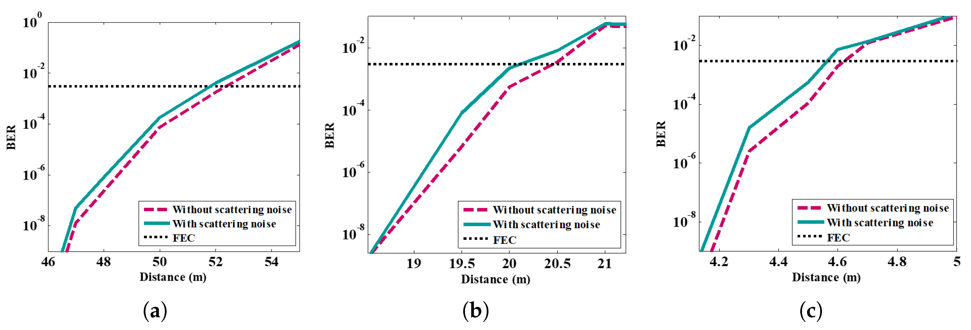
Figure 3 shows the scattering noise coefficient , which is mentioned in (10), as a function of the link range for the three types of waters based on the parameters in Table 1. N and are determined using MC simulation. Note, increases with the transmission link spans and b, which is the highest for the harbor water, where more photons experience scattering. Figure 4 depicts the BER performance as a function of the transmission distance for the proposed UOWC system with and without the scattering noise and for three types of waters.
As shown in Figure 4, the scattering noise results in increased BER for all three types of waters. However, this effect is less pronounced for the clear water compared with the coastal and harbor waters. This is mainly due to the coefficient, which is lower for the clear water, see Figure 4a. Note, for the clear water and at the FEC limit of and considering the scattering noise, the received power is −20 dBm for the 52 m link distance, which are comparable with [17,18]. For the coastal water, the scattering noise impact is more evident, as depicted in Figure 4b, where the BER is higher compared with the case with no scattering noise. In this case, the received power level at the FEC limit of is −19 dBm. For the harbor water, the BER performance is also affected by the scattering noise and is marginally higher than the coastal water, see Figure 4c, with considerably reduced link distance. Considering the scattering noise, the received power is −19 dBm at the FEC limit of , which is almost the same as [18]. Note, at the FEC limit of and considering the scattering noise, the maximum link spans are 20 and 4.6 m for the coastal and harbor waters, respectively, which are marginally shorter than those reported in [16,17]. Higher scattering noise coefficient results in increased BER performance degradation.
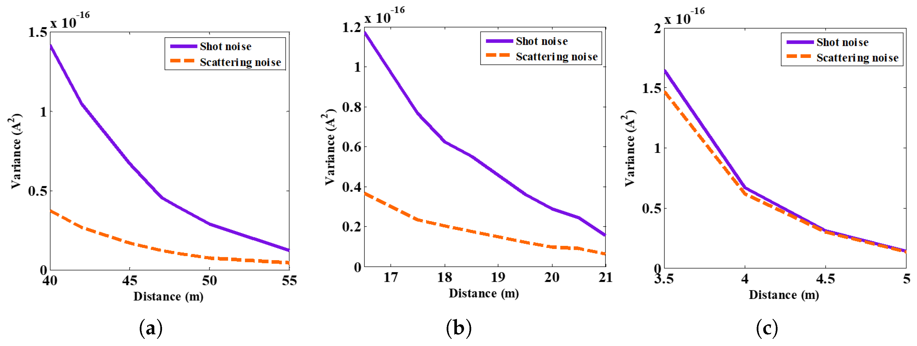
Figure 5 illustrates the variance of the scattering noise and compares it with shot noise as a function of the link distance. As shown, for dirtier water or the longer link distances, the variance plots are almost the same for both noise sources. This shows that in some conditions, scattering noise is comparable with shot noise and can not be neglected. In dirtier waters or over longer transmission link spans, more propagating photons will experience scattering, which will result in increased scattering noise coefficient , see Figure 3. As shown in Figure 5, the scattering noise variance increases with the distance and becomes almost the same as shot noise variance based on (11). At longer transmission distances, most photons experience scattering (i.e., ), arriving at random times producing scattering noise the same as shot noise in the photodiode which all the absorbed photons in the photodiode produce carriers at random times. Thus scattering noise is equal to the shot noise under these conditions.
6. Conclusions
In this paper, we introduced a new source of noise caused by the number of photons experiencing scattering along the propagation path. In dirtier waters or over longer transmission link spans, this noise (i.e., the scattering noise) is more or less the same as the signal-dependent shot noise. We determined the IR based on MC for three types of waters, which is affected by both the scattering and absorption. We introduced the coefficient and show that it is a function of the transmission distance for the clear, coastal, and harbor waters, where for longer link distances and dirtier waters, it approached the unity. For the clear, coastal and harbor waters and beyond the transmission spans of 90, 40 and 6.5 m, respectively, also approached one. The BER as a function of the transmission distance was compared for the links with and without the scattering noise as well as the shot noise, thermal noise, dark current noise, and background noise. The results demonstrated that for three types of waters, the scattering noise is not negligible; however, its effect is more prominent in the coastal and harbor waters due to higher coefficient. The variance of the shot noise and the scattering noise for three types of waters was also calculated, where the dirtier waters or longer link ranges both showed the same variances.
Author Contributions
Conceptualization, B.M.; methodology, B.M.; software, B.M.; validation, B.M., A.G.; formal analysis, B.M.; investigation, B.M.; resources, B.M.; data curation, B.M.; writing—original draft preparation, B.M.; writing—review and editing, A.G.and Z.G.; supervision, A.G.and Z.G. All authors have read and agreed to the published version of the manuscript.
Funding
This research received no external funding.
Conflicts of Interest
The authors declare no conflict of interest.
References
- Shen, C.; Guo, Y.; Oubei, H.M.; Ng, T.K.; Liu, G.; Park, K.H.; Ho, K.T.; Alouini, M.S.; Ooi, B.S. 20-m underwater wireless optical communication link with 1.5 Gbps data rate. Opt. Express 2016, 24, 25502–25509. [Google Scholar] [CrossRef]
- Celik, A.; Saeed, N.; Al-Naffouri, T.Y.; Alouini, M.S. Modeling and performance analysis of multihop underwater optical wireless sensor networks. In Proceedings of the 2018 IEEE Wireless Communications and Networking Conference (WCNC), Las Vegas, NV, USA, 15–18 April 2018; pp. 1–6. [Google Scholar]
- Zeng, Z.; Fu, S.; Zhang, H.; Dong, Y.; Cheng, J. A survey of underwater optical wireless communications. IEEE Commun. Surv. Tutor. 2016, 19, 204–238. [Google Scholar] [CrossRef]
- Saeed, N.; Celik, A.; Al-Naffouri, T.Y.; Alouini, M.S. Underwater optical wireless communications, networking, and localization: A survey. Ad Hoc Netw. 2019, 94, 101935. [Google Scholar] [CrossRef] [Green Version]
- Akyildiz, I.F.; Pompili, D.; Melodia, T. Underwater acoustic sensor networks: Research challenges. Ad Hoc Netw. 2005, 3, 257–279. [Google Scholar] [CrossRef]
- Pompili, D.; Akyildiz, I.F. Overview of networking protocols for underwater wireless communications. IEEE Commun. Mag. 2009, 47, 97–102. [Google Scholar] [CrossRef]
- Oubei, H.M.; Li, C.; Park, K.H.; Ng, T.K.; Alouini, M.S.; Ooi, B.S. 2.3 Gbit/s underwater wireless optical communications using directly modulated 520 nm laser diode. Opt. Express 2015, 23, 20743–20748. [Google Scholar] [CrossRef]
- Ballal, T.; Al-Naffouri, T.Y.; Ahmed, S.F. Low-complexity Bayesian estimation of cluster-sparse channels. IEEE Trans. Commun. 2015, 63, 4159–4173. [Google Scholar] [CrossRef] [Green Version]
- Kaushal, H.; Kaddoum, G. Underwater optical wireless communication. IEEE Access 2016, 4, 1518–1547. [Google Scholar] [CrossRef]
- Uysal, M.; Capsoni, C.; Ghassemlooy, Z.; Boucouvalas, A.; Udvary, E. Optical Wireless Communications: An Emerging Technology; Springer: Berlin/Heidelberg, Germany, 2016. [Google Scholar]
- Celik, A.; Saeed, N.; Shihada, B.; Al-Naffouri, T.Y.; Alouini, M.S. End-to-end performance analysis of underwater optical wireless relaying and routing techniques under location uncertainty. IEEE Trans. Wirel. Commun. 2019, 19, 1167–1181. [Google Scholar] [CrossRef]
- Jamali, M.V.; Nabavi, P.; Salehi, J.A. MIMO underwater visible light communications: Comprehensive channel study, performance analysis, and multiple-symbol detection. IEEE Trans. Veh. Technol. 2018, 67, 8223–8237. [Google Scholar] [CrossRef]
- Qadar, R.; Bin Qaim, W.; Nurmi, J.; Tan, B. Effects of Multipath Attenuation in the Optical Communication-Based Internet of Underwater Things. Sensors 2020, 20, 6201. [Google Scholar] [CrossRef]
- Guerra, V.; Rufo, J.; Rabadan, J.; Perez-Jimenez, R. Effect of moving microalgae on underwater wireless optical links. Appl. Opt. 2020, 59, 515–520. [Google Scholar] [CrossRef] [PubMed]
- Tang, S.; Dong, Y.; Zhang, X. Impulse response modeling for underwater wireless optical communication links. IEEE Trans. Commun. 2013, 62, 226–234. [Google Scholar] [CrossRef]
- Gabriel, C.; Khalighi, M.A.; Bourennane, S.; Léon, P.; Rigaud, V. Monte-Carlo-based channel characterization for underwater optical communication systems. J. Opt. Commun. Netw. 2013, 5, 1–12. [Google Scholar] [CrossRef] [Green Version]
- Oubei, H.M.; ElAfandy, R.T.; Park, K.H.; Ng, T.K.; Alouini, M.S.; Ooi, B.S. Performance evaluation of underwater wireless optical communications links in the presence of different air bubble populations. IEEE Photonics J. 2017, 9, 1–9. [Google Scholar] [CrossRef] [Green Version]
- Li, J.; Ma, Y.; Zhou, Q.; Zhou, B.; Wang, H. Monte Carlo study on pulse response of underwater optical channel. Opt. Eng. 2012, 51, 066001. [Google Scholar] [CrossRef]
- Li, J.; Ma, Y.; Zhou, Q.; Zhou, B.; Wang, H. Channel capacity study of underwater wireless optical communications links based on Monte Carlo simulation. J. Opt. 2011, 14, 015403. [Google Scholar] [CrossRef]
- Majlesein, B.; Gholami, A.; Ghassemlooy, Z. The channel impulse response of SIMO underwater optical wireless communication link based on monte carlo simulation. In Proceedings of the IEEE 2019 2nd West Asian Colloquium on Optical Wireless Communications (WACOWC), Tehran, Iran, 27–28 April 2019; pp. 69–73. [Google Scholar]
- Sticklus, J.; Hieronymi, M.; Hoeher, P.A. Effects and constraints of optical filtering on ambient light suppression in LED-based underwater communications. Sensors 2018, 18, 3710. [Google Scholar] [CrossRef] [Green Version]
- Jaruwatanadilok, S. Underwater wireless optical communication channel modeling and performance evaluation using vector radiative transfer theory. IEEE J. Sel. Areas Commun. 2008, 26, 1620–1627. [Google Scholar] [CrossRef]
- Winzer, P.J. Shot-noise formula for time-varying photon rates: A general derivation. JOSA B 1997, 14, 2424–2429. [Google Scholar] [CrossRef]
- Zmuidzinas, J. Thermal noise and correlations in photon detection. Appl. Opt. 2003, 42, 4989–5008. [Google Scholar] [CrossRef] [PubMed] [Green Version]
- Majlesein, B.; Gholami, A.; Ghassemlooy, Z. A complete model for underwater optical wireless communications system. In Proceedings of the 2018 IEEE 11th International Symposium on Communication Systems, Networks & Digital Signal Processing (CSNDSP), Budapest, Hungary, 18–20 July 2018; pp. 1–5. [Google Scholar]
- Cox, W.C., Jr. Simulation, Modeling, and Design of Underwater Optical Communication Systems. Ph.D. Dissertation, Department of Electrical and Computer Engineering, North Carolina State University, Raleigh, NC, USA, 2012. [Google Scholar]
- Dalgleish, F.R.; Caimi, F.M.; Vuorenkoski, A.K.; Britton, W.B.; Ramos, B.; Giddings, T.E.; Shirron, J.J.; Mazel, C.H. Efficient laser pulse dispersion codes for turbid undersea imaging and communications applications. In Ocean Sensing and Monitoring II; International Society for Optics and Photonics: Bellingham, WA, USA, 2010; Volume 7678, p. 76780I. [Google Scholar]
- Qadar, R.; Kasi, M.K.; Kakar, F.A. Monte Carlo based estimation and performance evaluation of temporal channel behavior of UWOC under multiple scattering. In Proceedings of the IEEE OCEANS 2017-Anchorage, Anchorage, AK, USA, 18–21 September 2017; pp. 1–7. [Google Scholar]
- Qadar, R.; Kasi, M.K.; Ayub, S.; Kakar, F.A. Monte Carlo–based channel estimation and performance evaluation for UWOC links under geometric losses. Int. J. Commun. Syst. 2018, 31, e3527. [Google Scholar] [CrossRef]
- Mao, Y.; Wu, X.; Huang, W.; Liao, Q.; Deng, H.; Wang, Y.; Guo, Y. Monte Carlo-Based Performance Analysis for Underwater Continuous-Variable Quantum Key Distribution. Appl. Sci. 2020, 10, 5744. [Google Scholar] [CrossRef]
- Schirripa Spagnolo, G.; Cozzella, L.; Leccese, F. Underwater optical wireless communications: Overview. Sensors 2020, 20, 2261. [Google Scholar] [CrossRef] [PubMed]
- Gholami, A.; Toffano, Z.; Destrez, A.; Pellevrault, S.; Pez, M.; Quentel, F. Optimization of VCSEL spatiotemporal operation in MMF links for 10-Gb ethernet. IEEE J. Sel. Top. Quantum Electron. 2006, 12, 767–775. [Google Scholar] [CrossRef]
Figure 1.
System model.
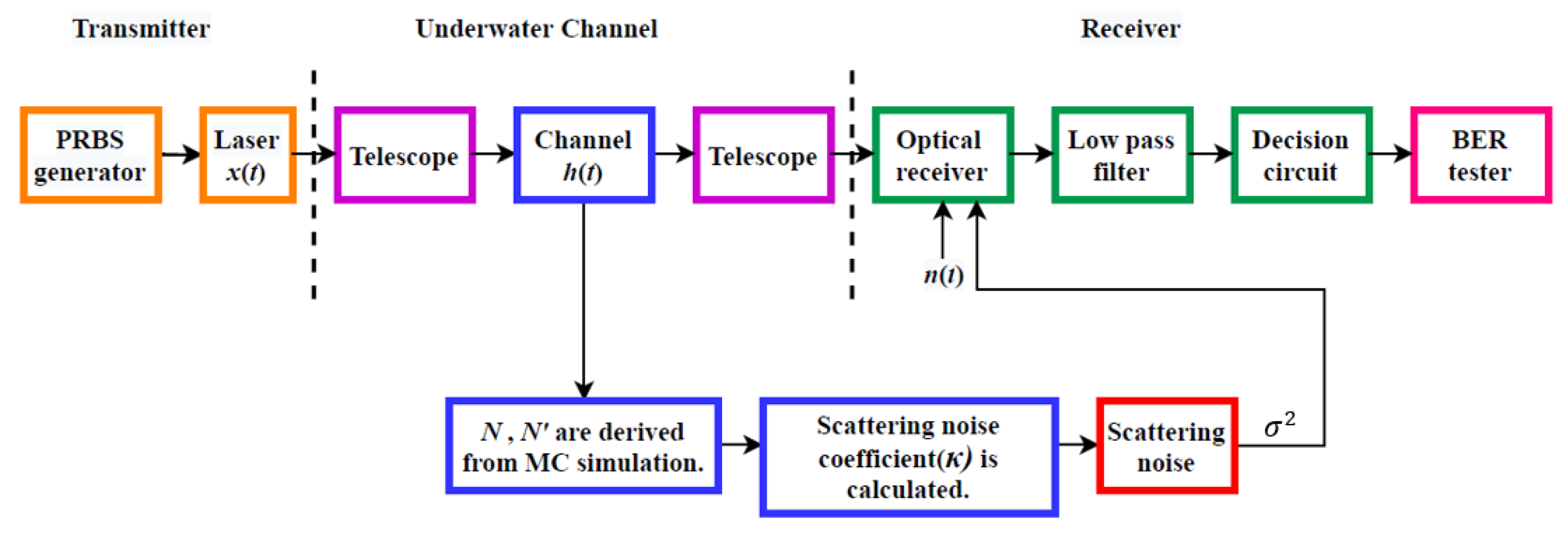
Figure 2.
The impulse responses for three types of water: clear (50 m), coastal (20 m) and harbor (4 m).
Figure 2.
The impulse responses for three types of water: clear (50 m), coastal (20 m) and harbor (4 m).
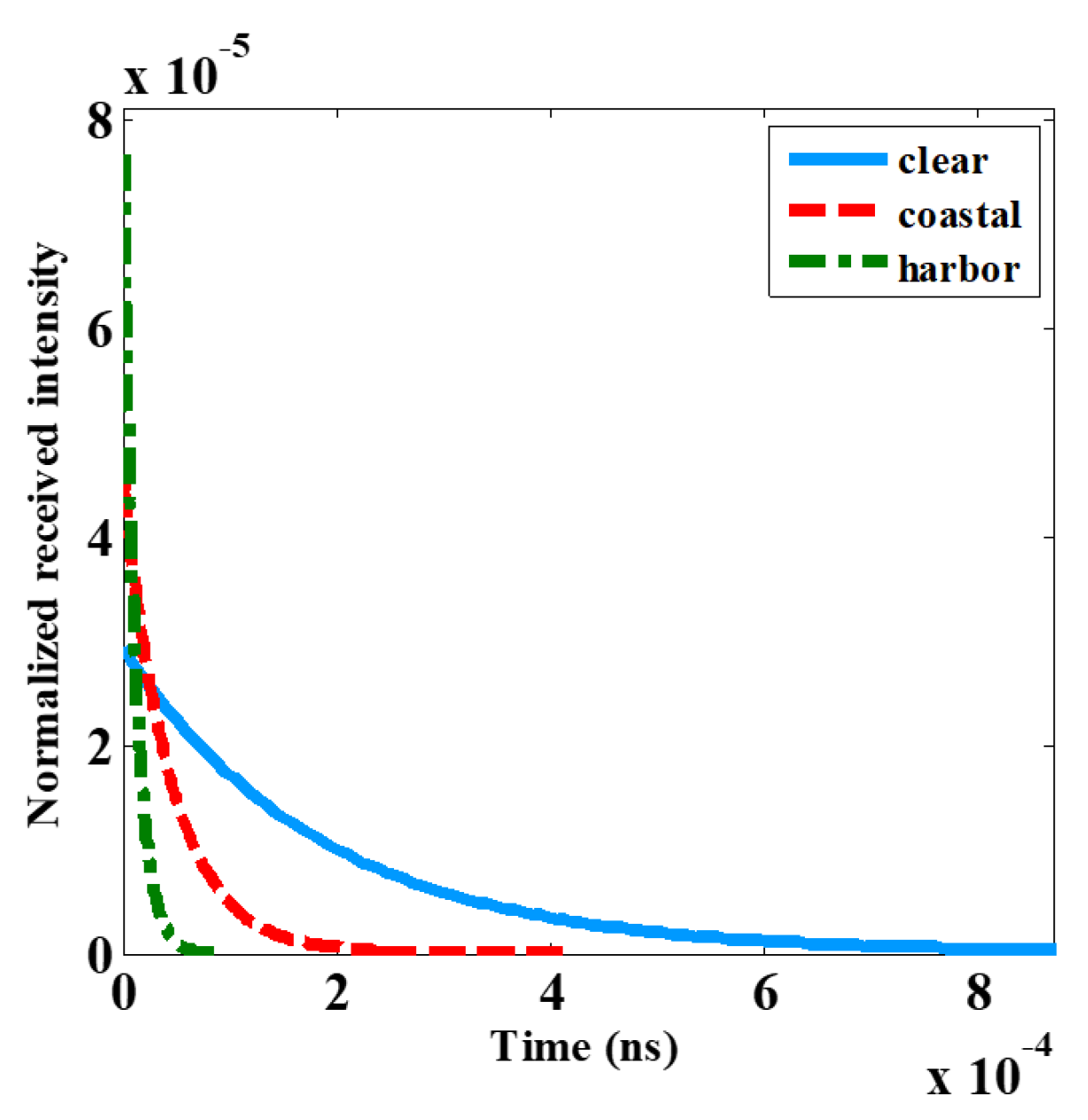
Figure 3.
The scattering noise coefficient() against the link distance for clear, coastal and harbor waters.
Figure 3.
The scattering noise coefficient() against the link distance for clear, coastal and harbor waters.
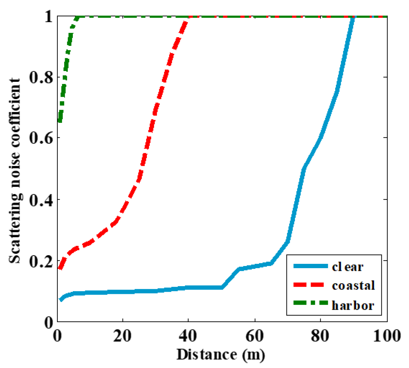
Figure 4.
The BER performance against the link distance: (a) clear, (b) coastal, and (c) harbor.

Figure 5.
The variance (shot noise and scattering noise) against the link distance for three types of water: (a) clear, (b) coastal and (c) harbor.
Figure 5.
The variance (shot noise and scattering noise) against the link distance for three types of water: (a) clear, (b) coastal and (c) harbor.


Table 1.
Water Parameters.
| Water Type | Albedo (, Scattering Coefficient) | |
|---|---|---|
| Clear | 0.151 | 0.245 |
| Coastal | 0.398 | 0.55 |
| Harbor | 2.17 | 0.83 |
Table 2.
System Parameters.
| Parameter | Value |
|---|---|
| Laser wavelength () | 517 nm |
| Laser beam divergence | 0.75 mrad |
| Beam width | 0.001 mm |
| Optical power | 50 mW |
| Data rate | 500 Mbps |
| Low pass filter bandwidth () | 300 MHz |
| Photodetector responsivity (R) | 0.34 A/W |
| Gain of amplifier (G) | 600 V/A |
| Rx’s field of view | 180° |
| Radius size of aperture | 10 cm |
Publisher’s Note: MDPI stays neutral with regard to jurisdictional claims in published maps and institutional affiliations. |
© 2021 by the authors. Licensee MDPI, Basel, Switzerland. This article is an open access article distributed under the terms and conditions of the Creative Commons Attribution (CC BY) license (https://creativecommons.org/licenses/by/4.0/).
Share and Cite
MDPI and ACS Style
Majlesein, B.; Gholami, A.; Ghassemlooy, Z. Investigation of the Scattering Noise in Underwater Optical Wireless Communications. Sci 2021, 3, 27. https://0-doi-org.brum.beds.ac.uk/10.3390/sci3020027
AMA Style
Majlesein B, Gholami A, Ghassemlooy Z. Investigation of the Scattering Noise in Underwater Optical Wireless Communications. Sci. 2021; 3(2):27. https://0-doi-org.brum.beds.ac.uk/10.3390/sci3020027
Chicago/Turabian StyleMajlesein, Behnaz, Asghar Gholami, and Zabih Ghassemlooy. 2021. "Investigation of the Scattering Noise in Underwater Optical Wireless Communications" Sci 3, no. 2: 27. https://0-doi-org.brum.beds.ac.uk/10.3390/sci3020027