
Accuracy and Repeatability Tests on HoloLens 2 and HTC Vive


1
Department of Electrical and Computer Engineering, Faculdade de Engenharia da Universidade do Porto, FEUP, 4200-465 Porto, Portugal
2
INESC TEC—Institute for Systems and Computer Engineering, Technology and Science, 4200-465 Porto, Portugal
*
Author to whom correspondence should be addressed.
Multimodal Technol. Interact. 2021, 5(8), 47; https://0-doi-org.brum.beds.ac.uk/10.3390/mti5080047
Submission received: 22 July 2021
/
Revised: 9 August 2021
/
Accepted: 16 August 2021
/
Published: 23 August 2021
(This article belongs to the Special Issue Feature Papers of MTI in 2021)
Abstract
:Augmented and virtual reality have been experiencing rapid growth in recent years, but there is still no deep knowledge regarding their capabilities and in what fields they could be explored. In that sense, this paper presents a study on the accuracy and repeatability of Microsoft’s HoloLens 2 (augmented reality device) and HTC Vive (virtual reality device) using an OptiTrack system as ground truth. For the HoloLens 2, the method used was hand tracking, whereas, in HTC Vive, the object tracked was the system’s hand controller. A series of tests in different scenarios and situations were performed to explore what could influence the measures. The HTC Vive obtained results in the millimeter range, while the HoloLens 2 revealed not very accurate measurements (around 2 cm). Although the difference can seem to be considerable, the fact that HoloLens 2 was tracking the user’s hand and not the system’s controller made a huge impact. The results are considered a significant step for the ongoing project of developing a human–robot interface by demonstrating an industrial robot using extended reality, which shows great potential to succeed based on our data.
1. Introduction
Fang et al. [1] defined human–robot Interaction (HRI) as “the process that conveys the human operators’ intention and interprets the task descriptions into a sequence of robot motions complying with the robot capabilities and the working requirements”. This interaction can also be defined as a situation where humans and robots work as a team in order to reach a common goal. Each application of HRI demands a different level of interaction, and such a level is identified depending on two principles [1]: autonomy degree of the robotic system and proximity of human and robot during operation.
Augmented Reality (AR), Virtual Reality (VR) and Mixed Reality (MR) are well-known technologies applied in different areas with different purposes. Game environments, educational contents and medicine are some of the applications. Augmented reality refers to when virtual objects and information are overlaid on the real world. In virtual reality, in contrast to AR, the users experience a world completely virtual, and are fully immersed in a simulated digital environment. The technology that integrates both AR and VR is called mixed reality, where digital and real objects co-exist and can interact with each other in real time [2]. Augmented reality, virtual reality and mixed reality are well-known immersive technologies applied in different areas with different purposes. They have already been applied not only in games and entertainment, but also in industry (to train and display information to the operator) [3], healthcare (more specifically, in performing surgeries) [4], real state (layout scenarios) [5], and even grocery shopping (providing nutrition facts, health and wellness tips, and unhealthy selection warnings) [6].
Several devices may be used to allow these immersive environments. In terms of AR, the most used are Microsoft HoloLens, Magic Leap One, Epson Moverio and Google Glass. As For VR, the most used are HTC Vive, Oculus Quest, Valve Index and Sony PlayStation VR.
The purpose of this paper is to present a study carried out examining the accuracy and repeatability of the Microsoft HoloLens 2 (AR) and HTC Vive (VR) devices, as well as the results obtained and suitable applications for each device in the robotic area. This study is integrated into a wider project whose final purpose is to develop an industrial prototype of a human–machine interaction system through Extended Reality (XR), in which the objective is to enable an industrial operator without any programming experience to program a collaborative robot using XR devices. In this regard, this paper provides a better understanding regarding the system’s possibilities in terms of accuracy.
The remaining sections of this paper are organized as follows. Section 2 presents a literature review on the XR system’s accuracy. Section 3 gives a detailed description of the methodology used for the tests’ execution, the setup of each technology, the data synchronization methods, the data analysis process and the tests performed. Section 4 discloses the tests’ results and discusses their tenor and meaning, as well as some of the suitable applications for each device according to the results obtained. Ultimately, Section 5 presents the conclusion and suggestions for future work.
2. Related Work
Programming by demonstration can be a very important tool for an operator that does not have experience or knowledge with programming at all. This way they would be able to program the robot just by doing the task themselves and then the robot would do the same. Therefore, the study of the accuracy and repeatability of the XR systems is extremely important in order to be aware of their limitations.
Rudorfer et al. [7] presented an intuitive drag-and-drop programming method using augmented reality that could be performed by an operator without robot programming knowledge. In the implementation the devices used were the Microsoft HoloLens and the UR5 robot, integrated into a framework of web services. The main objective was for the user to pick a recognized object and place it in a desired location, so that the robot could imitate. The robot started by acquiring the image, then it recognized the object and its pose. After recognizing all objects, the objects were displayed in the AR device, overlaid on the real ones. Then, the robot control module extracted the initial and final coordinates of the desired locations and performed the referential transformations from the camera referential to the robot referential. Finally, the pick and place task could be executed. The results obtained by the prototype developed were successful but the robot’s accuracy was unsatisfactory, mostly because they based the target position on the intersection of the user’s gaze with the platform, which imposed limitations on the system’s accuracy.
Blankemeyer et al. [8] developed an AR application for HoloLens, and the prime objective was to enable operators to program a pick-and-place task in an industrial robot by linking real and virtual objects. For that, the user had to move the virtual object to the desired position. Next, the coordinates of the start and end points had to be transformed from the internal coordinate system of the HoloLens into the robot’s base coordinate system. Finally, the trajectory planning was carried out directly by the robot controller. The results to the tests performed showed that the robot was able to complete the tasks with two components, but the researches assured that the same can be expected when adding more components. The accuracy and repeatability of the system were measured by calculating the difference of the virtual and real objects, reaching values of 1–2 mm for accuracy and 3–5 mm for repeatability.
Spitzley and Karduna [9] studied the possibility to use the HTC Vive VR system for kinematic data collection by evaluating the accuracy of the position and orientation data. The study was made on the HTC Vive controller and tracker in comparison to a Polhemus Liberty magnetic tracking system sensor for angular and translational measurement errors and signal drift. The mean errors obtained for both the hand controller and the tracker were below 3 mm for translational movements and the angular errors were below 0.4 degrees. The authors concluded that the system would be suitable and reliable for kinematic data collection; nevertheless they admitted that further investigation in necessary to accurately determine the system’s capability for capturing high-volume movements. Furthermore, the Magnetic tracker was easily disturbed by metallic objects, which limits its use.
Niehorster et al. [10] also confirmed the HTC Vive system’s high accuracy and precision, which they validated through a quantitative test of the position and orientation. However, they concluded that the system’s latency was low (around 22 ms). Additionally, they found that when data were briefly lost, there was some variations in offsets, which led to the conclusion that, in those conditions, the HTC Vive system would not be suitable for scientific experiments that require accurate visual stimulation of self-motion.
The results obtained are promising and show that it is possible for an operator without any robot programming knowledge to program a collaborative robot by teaching it the desired task. One of the problems found in these researches was the lack of accuracy experienced by the robot in the picking and placing task. In this study, repeatability and accuracy were the focus of our methodology, comparing the results obtained from extended reality devices to a precision tracking system.
3. Materials and Methods
The prime objective of this work was to measure the accuracy and repeatability of the HoloLens 2 (HL2) and HTC Vive devices. To this end, we used the OptiTrack system as a ground truth due to its submillimeter accuracy. Figure 1 represents an overview of the system developed for these tests. The data acquired by the extended reality devices and the OptiTrack system are sent to the Robot Operating System (ROS), where they are synchronized. After that, in MATLAB, the data are analyzed and the accuracy, repeatability and possible delays are calculated. Additionally, some plots to illustrate the results are drawn.
3.1. Ground Truth Setup
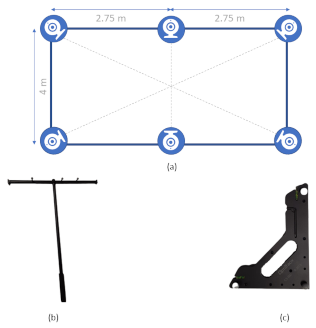
The OptiTrack system used was made up of six Flex3 InfraRed cameras, four of them forming the vertices of a rectangle and the other two in the center of the biggest edges (Figure 2a). All of the cameras were set up in the same plane (around 2.75 m high) and covered a total area of 22 squared meters, but the area used to avoid occlusions was about 12 square meters. The cameras were oriented toward the center of the rectangle, which allowed a common ground between all cameras and minimized the markers’ occlusions, and a full calibration using the OptiTrack software and hardware tool (Figure 2b) was performed. From that we obtained a mean 3D reprojection error of 0.791 millimeters.
After calibration, the ground plane was set using OptiTrack plane calibration tool (Figure 2c). This object had a shape of a squared triangle with three markers, one in each vertex, so that the system could identify the desired coordinate frame. One of the markers corresponds to the frame’s origin and the other two to points on the x and z axes; in this way the referential is defined taking into account that the y axis points upwards.
OptiTrack markers are small reflective spheres with a 14 mm diameter (observable in Figure 2c). It is possible to acquire data from different types of assets: rigid body, skeleton and unlabelled markers. For the specific case of this study, it would be ideal to stream data from unlabelled markers, because it would only be necessary to place one marker on the user’s hand. However, this method is not reliable because the probability of the system losing track of the marker was very high, so the asset used was a rigid body because it is more accurate and trustworthy.
The system broadcasts the rigid body pose through the Virtual Reality Peripheral Network (VRPN) streaming engine. To process the data, the software framework Robot Operating System (ROS) was used. The ROS package used to receive the data from OptiTrack was vrpn_client_ros. The message received from OptiTrack was in geometry_msgs/PoseStamped format, which contains a header with a timestamp and the position and orientation of the rigid body. For this study the orientation was not considered.
3.2. HoloLens 2 Setup
As the position reference is a rigid body from the OptiTrack system, it was necessary to print a 3D structure to hold the OptiTrack markers. The point considered for the HoloLens 2 measures was the tip of the index finger, and therefore a rigid body was built so that its center was in the same place. There were some concerns in the construction of the rigid body, which are listed below:
- It should not be symmetrical because the OptiTrack system could be confused in some orientations;
- The minimum number of markers was three but we opted to insert four, increasing the robustness of the rigid body detection; this way if one was hidden the system would continue tracking;
- The markers could not be close to each other, otherwise the system would not be able to track it properly.
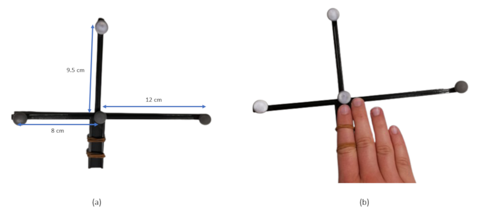
Taking all these limitations into consideration, the piece built had the shape of a cross, three of the markers formed a scalene triangle and the forth marker was placed at the center of the cross; see Figure 3a. Additionally, the forth edge had the purpose of supporting the index finger (secured by two rubber bands), resulting in its tip touching the center marker of the rigid body. The resulting rigid body is represented in Figure 3b.
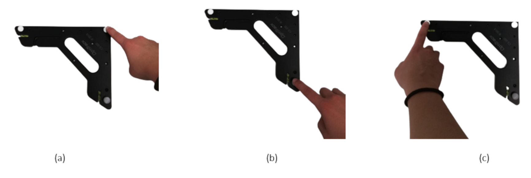
The HoloLens 2 automatically defines a coordinate system when the application is launched. Thus, in order to be able to directly compare the coordinates from OptiTrack and HL2, it was necessary to define a different referential to match the one from OptiTrack. Because the HL2 software does not allow to define a secondary referential, it was necessary to perform some workarounds. The simplest method found was to place an object (a cube in this specific case) in the origin of the coordinate system and then calculate the hand coordinates in relation to that object. To define the cube’s position and orientation, we used the OptiTrack instrument for ground plane definition so that the coordinate systems would be exactly the same. To define the coordinate system in the HoloLens 2 application, we used the user’s right index finger tip, as is explained below.
- 1.
- First, in order to define the cube’s origin position, the user clicks on the interface button, suggesting that he/she ready to start defining the referential.
- 2.
- After clicking the button, the user has five seconds to place the right index finger tip on the OptiTrack coordinate system origin (Figure 4a). When that time is up, the system will save the coordinates where the right index finger tip is as the cube’s point of origin.
- 3.
- Then, the user clicks the button again and has five seconds to place the finger at the second point, which defines the point on the X axis (Figure 4b).
- 4.
- The same happens with the third point (Figure 4c).
- 5.
- Lastly, the user clicks the button again to confirm that the referential is correctly set and the cube appears at the defined origin with the specified orientation.
The HL2 application to stream the hand position was built in Unity using Microsoft’s Mixed Reality Toolkit [11]. In order to establish a connection with ROS, we used the ROS# [12] libraries. To be able to directly compare the message from HL2 and OptiTrack, the application streams to an ROS topic a PoseStamped message containing the timestamp and the position of the user’s index finger tip; the orientation was set to zero because it was not used in this study.
3.3. HTC Vive Setup
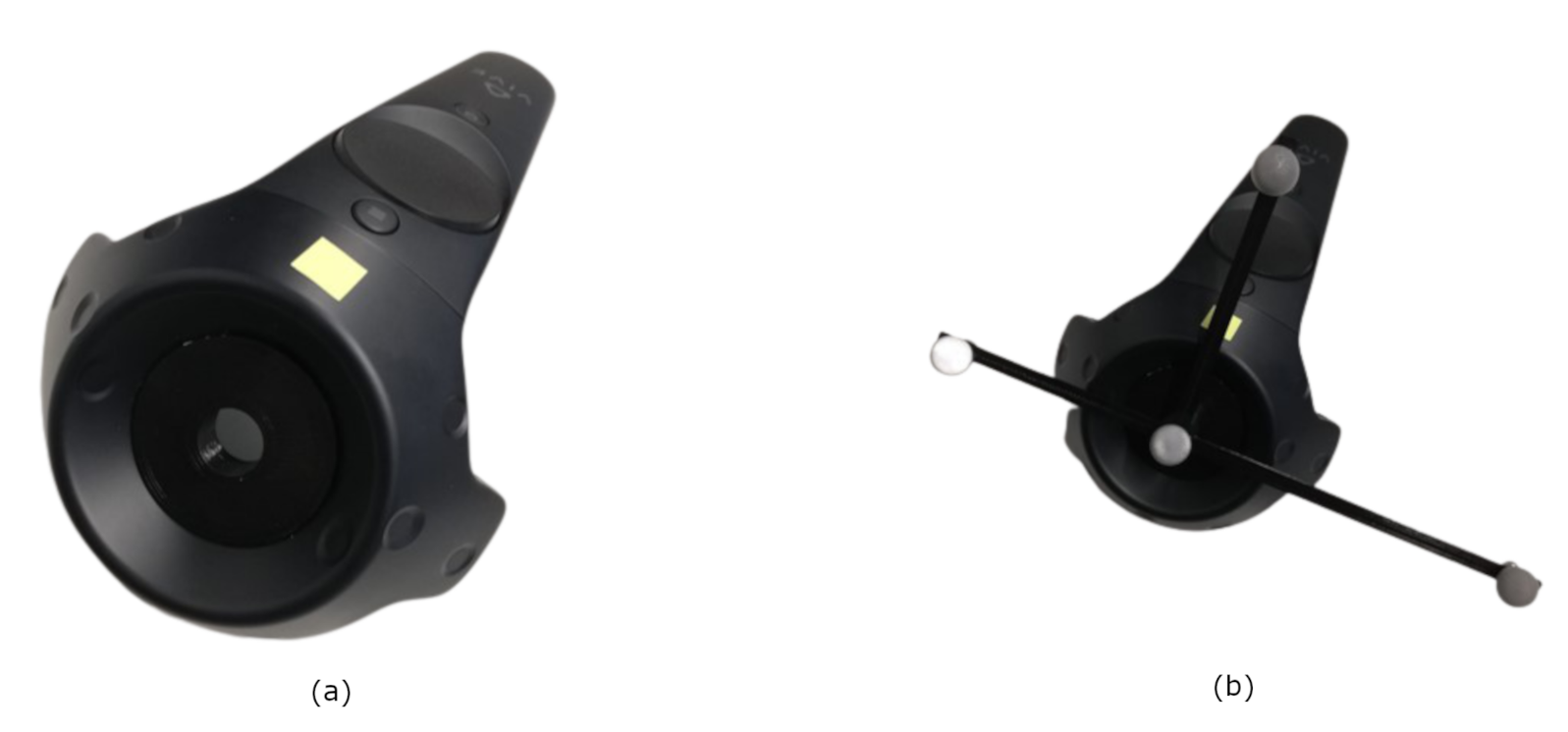
The HTC Vive is a virtual reality headset that has a set of two hand controllers. The HTC Vive system has two base stations to capture the optical signals from the controllers so that they can be tracked. These base stations were positioned at opposite corners with a 5 m distance from one another, and connected with a sync cable. Thus, instead of using the user’s hand, one of the controllers functioned as the tracking object to evaluate the accuracy and repeatability of the system. Furthermore, it was necessary to print a 3D structure, like in the HoloLens 2 application, that would represent the rigid body to track in OptiTrack. The main part of the piece was identical to the one described before, but instead of having a support to place the finger, it fitted in the controller’s center hole.
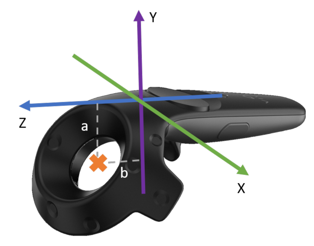
The origin of the controller’s reference frame is represented in Figure 5. The orange “x” in the figure illustrates the desired point to consider as the controller’s center for more accurate measurements. The rigid transformation between the frames was estimated using the controller’s CAD model (0.0; 0.030986; 0.01946 m) and implemented through the MRTK Solver system.
Similarly to HoloLens 2, the coordinate system definition was also set by three points using the OptiTrack plane calibration tool. However, instead of placing the index finger on the marker, it was placed on the controller, more specifically at the center of the controller’s toroid pointing downwards. To make the measurements well grounded, a piece that fitted the toroid’s cavity was printed, and in the center was an empty space that had the exact size needed to fit the reflective marker, Figure 6a.
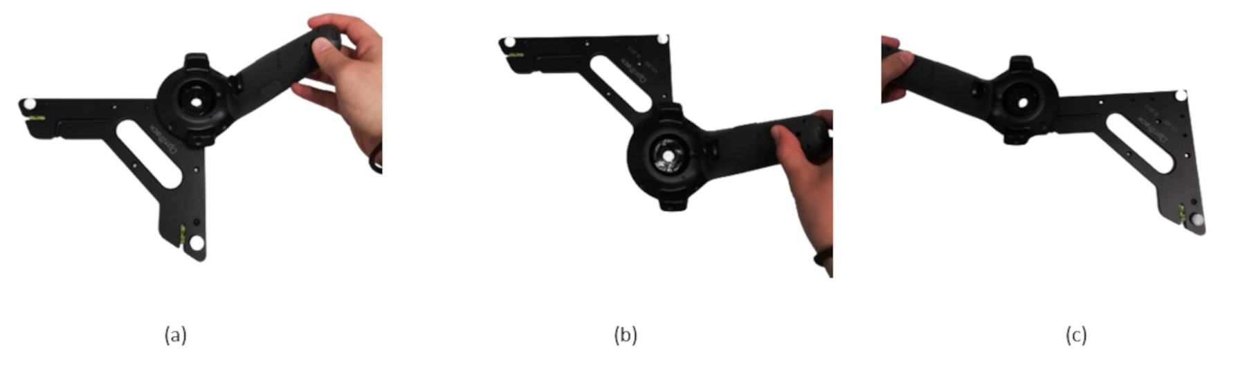
Figure 7 shows the sequence in which the application coordinate system was defined in HTC Vive, first defining the origin point, then the point on the X axis and, finally, the point on the Z axis. The list below describes this process in more detail:
- 1.
- First, in order to define the cube’s origin position, the user clicks with the controller on the interface button, suggesting that he/she is ready to start defining the referential.
- 2.
- After clicking the button, the user has five seconds to place the right controller upside-down on the OptiTrack coordinate system origin (Figure 7a). When that time is up, the system will save the controller’s coordinates as the cube’s point of origin.
- 3.
- Then, the user clicks the button again and has five seconds to place the controller at the second point, which defines the point on the X axis (Figure 7b).
- 4.
- The same happens with the third point (Figure 7c).
- 5.
- Lastly, the user clicks the button again to confirm that the referential is correctly set and the cube appears at the defined origin with the specified orientation.
After the coordinate frame definition, the above mentioned rigid body was fixed to the controller (Figure 6b), and the system was properly set up to begin tracking.
The data streaming was done identically as in HoloLens 2, using the ROS# library developed by Siemens.
3.4. Data Synchronization
Several tests were performed, which can be divided into two categories: the ones with motion and the ones without motion. The data synchronization for the tests without motion was performed using the ROS library message_filters. This filter subscribes to both topics (the OptiTrack data and the HL2 or HTC data) and synchronizes them accordingly to their timestamp that is included in the header. The policy used for synchronization was ApproximateTime because the rates of sampling were different, and therefore the timestamps could not be directly matched. The data were then exported to a csv file for further analysis.
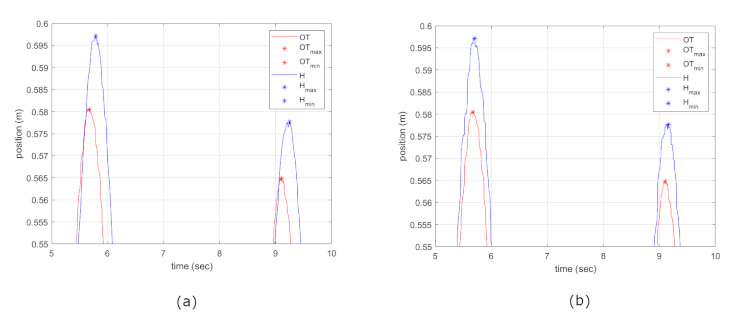
From the data acquired it was noted that the timestamp from HoloLens 2 had a small delay (less than one second). Thus, for the tests that involved movement, the synchronization through the timestamp would not work. For this reason, the tracking data were saved into a cvs file, and synchronization was performed a posteriori in Matlab. Figure 8 shows the signals’ representations of the OptiTrack and HoloLens 2 positions (the represented position refers to the z axis, as the subject only moved in that direction). To synchronize the data, the method used was to find the peaks (Figure 9a, maximum and minimum), and then calculate the difference between the corresponding points in the temporal axis (horizontal). Then, the delay calculated was the mean of those differences. According to the delay calculated, the signals were readjusted (Figure 9b), and then the accuracy was calculated. In the graph, it is also possible to verify some differences in the vertical axis between both signals, which indicates some errors in the position measurements, as will be discussed in Section 4.
3.5. Data Analysis
The data analysis was performed using MATLAB. For the tests without motion, the algorithm calculated the accuracy and the repeatability of each test.
The accuracy calculated the difference between the measured coordinates (, , ) from HL2/HTC and the ground truth (measures from OptiTrack: , , ). The equations used to calculate the accuracy were based on ISO 9283 [13] and are presented in (1), where n represents the number of samples, and , and refer to the coordinates’ errors in the reference frame.
where:
According to ISO 9283, the repeatability (), also called precision, determines the variance of the measured points and is calculated using the distance between the measured values (from HL2/HTC) and their mean value () and the standard deviation (), as shown in (3). are the mean of the measurements of each axis, and are the measurements of each axis in sample i [8].
where:
For the experiments that required motion of the user’s hand, the MATLAB algorithm first performed a synchronization, considering the time origin as the moment that ROS started receiving data and counting the time from that point. Because the sampling rate of OptiTrack was higher than HL2 and HTC, it was necessary to perform a data interpolation in these last two datasets. After the interpolation, both datasets were properly synchronized and had the same length, and it was possible to start the data analysis.
The data analysis for the motion experiments was focused on the accuracy (as in the previous tests) and delay calculation. It was verified that in HoloLens 2 the device had a small delay in detecting the hand movement: the hand’s hologram delay can be seen while moving the hand. Therefore, the algorithm first calculates the delay, then readjusts the vectors and then calculates the accuracy.
3.6. Experiments
The purpose of this study was to analyze the accuracy and repeatability of the HoloLens 2 hand tracking and the HTC Vive controller tracking. Therefore, several experiments were conducted to evaluate the tracking systems in different situations:
- When the tracking object was stationary;
- When the tracking object was moving at different velocities;
- When the HTC Vive system was measuring the controller’s position with only one base station;
- When using HL2 the user was always moving his/her head around;
- When measuring the HL2 hand tracking outside the center of the field vision;
- When tracking hands of different people (different hand sizes and shapes);
- When using the left hand to track instead of the right.
4. Results and Discussion
This section presents the results obtained with the experiments performed and a discussion is elaborated in order to draw conclusions. First the results for HTC Vive are presented, followed by those for Microsoft HoloLens 2.
4.1. HTC Vive
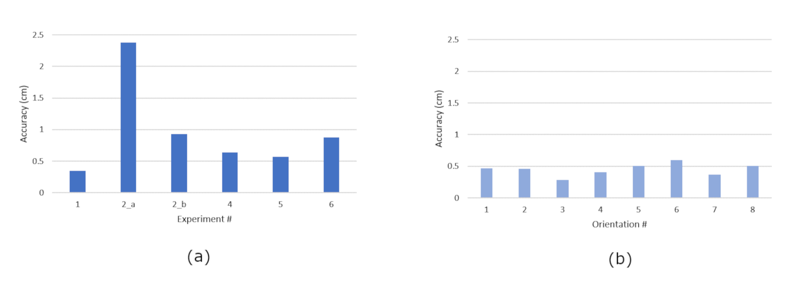
The results achieved in the experiments for HTC Vive were quite satisfactory (Figure 10). For the stationary experiment (#1), the accuracy obtained was of 3.5 mm and the repeatability was of 2.5 mm. When the measurements were being acquired by only one base station (#2), it was verified that the error increased significantly (in Figure 10a this experiment is divided into 2_a and 2_b, which represent the use of base stations A and B, respectively). For one of the base stations, it increased almost by more than six times in accuracy (resulting in 23.76 mm), but the increase in repeatability was not significant (1.84 mm). On the other hand, when the same experiment was carried out by the other base station, the accuracy only increased two-fold (7.31 mm), but the repeatability was almost four times higher (8.10 mm). The deterioration of the results agreed with our expectations, as HTC Vive was designed to be used with both base stations working simultaneously. These tests were performed in order to discover what the system’s reaction would be in case of a temporary occlusion of one of the base stations. The results from experiment #3 (Figure 10b), which measured the influence of the controller’s angle with the base stations, were also expected. It was verified that indeed some variation was noted not only in the accuracy but also in the repeatability. Nevertheless, the maximum variation observed in both was around 3 mm. From these results, it can be concluded that the controller’s orientation had some influence on the errors, but it was not significant. The different orientations were allocated through a full rotation of the hand controller, turning by 45 each time until reaching 360; in total there were eight different orientations and always the same position.
In the experiments with motion (#4, #5, #6), the accuracy obtained was worse than when the controller was stationary, but the variation was not linear, i.e., when the velocity increased the error did not increase accordingly. This set of experiments was performed more than one time and the results were quite inconsistent. For example, sometimes the test with medium velocity had the best accuracy (5.6 mm) while in other experiment sets it had the worst (13.4 mm). In all of the velocity tests performed, it was verified that the HTC Vive system did not have a significant delay in the measures acquisition when compared to the OptiTrack.
4.2. Microsoft HoloLens 2
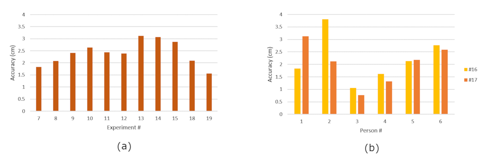
The results obtained with HoloLens 2 were significantly worse in comparison with the HTC Vive (Figure 11). However, this was expected, since HL2 depends on an algorithm to recognize the hand while the HTC Vive uses the inherited system controller with two base stations acquiring the infrared signals emitted by the controllers. For experiment #7, in which the right hand stopped in the center of vision field, the accuracy obtained was around 18.3 mm and the repeatability was 5.8 mm. While using the device, it is possible to verify that the hologram of the user’s hand is not exactly aligned with the hand and it has some variation, which turned out to be consistent with the results obtained. To analyze the influence of moving the head while tracking the hand, experiment #8 revealed a small improvement in the accuracy of about 13% and the repeatability doubled. Therefore, the main conclusion retrieved from these experiments was that the head movement has some influence on the measurements but not significantly enough so that it would be mandatory to have the head completely still during experiments.
Experiments #9 to #12 confirmed the supposition that errors are lower when the hand is positioned in center of the field of vision. The accuracy of the four experiments (corresponding to the four corners of the vision field) was between 23.9 and 26.3 mm, and the repeatability was between 5.9 and 7.2 mm. These results indicate that the hand’s position in relation to the projection vision field may influence the measured accuracy and repeatability.
The velocity experiments (experiments #13, #14, #15) had a delay of 65 milliseconds on average, which is observable while using the glasses: the hand’s hologram is behind the real hand when moving. The accuracy values estimated in these motion experiments were also not linear in response to speed variations. In fact, the results did not have a significant change, being around 30 mm for the three velocities.
To analyze the influence of different hand sizes and shapes, experiments #16 and #17 were conducted with six different volunteers. The results obtained were quite interesting (Figure 11b), observing a significant variation in the accuracy results. The best one had an accuracy around 10 mm, while the worst had an accuracy around 37.5 mm. Reaching the conclusion that the hand size and shape affect the measurements, the person that performed the best experiment had the biggest hand of all participants, and the worst accuracy result’s hand was the smallest. The motion experiments confirmed this conclusion, also verifying a difference of about 25 mm between the two extreme results.
Finally, experiments #18 and #19 showed some difference, although not significant, between the right and left hands (about 2.5 mm in accuracy when the hand was stopped), the right hand having the best result. In contrast to that result, in the movement experiment, the left hand presented the best result (20.9 mm against 31.2 mm of the right hand). In conclusion, right and left hands can have a small influence on the results, but it is neither linear nor predictable.
5. Conclusions
This work presented the study of accuracy and repeatability in HoloLens 2 and HTC Vive systems in comparison with the OptiTrack system that was considered as a reference. For the first device, the method used was hand tracking, while for the second one the object tracked was its controller. After performing a series of tests, it was concluded that both devices show great potential for a vast number of applications in various fields. However, HTC Vive presented better performance results, indicating that it would be more suitable than HoloLens 2 for applications that require high accuracy.
As a general rule, it can be concluded that HoloLens 2 would be more suitable for tasks that would not require high accuracy to achieve a good performance in tasks such as detection of intrusion in security areas, gesture recognition, and some painting applications. HTC Vive, on the other hand, would also be suitable for applications that require higher accuracy, such as tightening a screw on a car engine or welding metal pieces.
HTC Vive has already been used to improve the learning experience of medical students [14], and in a rehabilitation training program for upper limbs, where the patient would manipulate the controller according to the task requirements [15]. Flueratoru et al. [16] also claimed that HTC Vive could be used to acquire baseline measurements for the Ultra-wide-band system, whose accuracy and precision are in the range of centimeters. Kharvari and Hohl [17] tested the hypothesis of using VR in architectural education for studying precedents and found that it motivated the students to deepen their learning on the subject because of its interactivity.
As for HoloLens 2, it has already been used in industry to program industrial robots by demonstration, as was mentioned in Section 2. But it is important to note that not all robot applications would be suitable for this type of programming due to its limited accuracy. For example, it could be suitable for a pick and place application. Sharma et al. [18] were able to improve building evacuation time and eradicate injuries and fatalities during emergencies, thanks to a HoloLens application that provided visual representation of a building on campus in 3D space. HoloLens has also entered the field of nuclear power engineering, helping maintenance workers get tasks done faster by providing them with content of plant layout and key equipment as holographic images [19].
Lastly, this study was a significant step and the base of the ongoing project of developing a human–robot interface to program by demonstration an industrial robot using augmented reality.
Author Contributions
Conceptualization, I.S., M.P. and A.P.M.; methodology, I.S.; software, I.S.; validation, I.S., R.B.S., M.P. and A.P.M.; investigation, I.S.; writing—original draft preparation, I.S.; writing—review and editing, I.S., R.B.S., M.P. and A.P.M.; supervision, M.P. and A.P.M.; funding acquisition, M.P. and A.P.M. All authors have read and agreed to the published version of the manuscript.
Funding
This work was realized within the scope of the project PRODUTECH4SC—POCI-01-0247-FEDER-046102, funded by the ERDF—European Regional Development Fund, through the Operational Programme for Competitiveness and Internationalisation—COMPETE 2020.
Institutional Review Board Statement
The study was conducted according to the guidelines of the Declaration of Helsinki.
Informed Consent Statement
Informed consent was obtained from all participants involved in the study.
Data Availability Statement
All data are contained within the manuscript. Raw data are available from the corresponding author upon request.
Conflicts of Interest
The authors declare no conflict of interest.
Abbreviations
The following abbreviations are used in this manuscript:
| AR | Augmented Reality |
| HL2 | HoloLens 2 |
| MR | Mixed Reality |
| MRTK | Mixed Reality Toolkit |
| ROS | Robot Operating System |
| VR | Virtual Reality |
| XR | Extended Reality |
References
- Fang, H.C.; Ong, S.K.; Nee, A.Y. A novel augmented reality-based interface for robot path planning. Int. J. Interact. Des. Manuf. 2014, 8, 33–42. [Google Scholar] [CrossRef]
- Gironacci, I.; Vincs, K.; Mccormick, J. A Recommender System of Extended Reality Experiences. In Proceedings of the 2020 3rd International Conference on Image and Graphics Processing, Singapore, 8–10 February 2020. [Google Scholar] [CrossRef]
- De Pace, F.; Manuri, F.; Sanna, A. Augmented Reality in Industry 4.0. Am. J. Comput. Sci. Inf. Technol. 2018, 6, 17. [Google Scholar] [CrossRef]
- Rahul, K.; Raj, V.P.; Srinivasan, K.; Deepa, N.; Kumar, N.S. A Study on Virtual and Augmented Reality in Real-Time Surgery. In Proceedings of the 2019 IEEE International Conference on Consumer Electronics-Taiwan, ICCE-TW 2019, Yilan, Taiwan, 20–22 May 2019. [Google Scholar] [CrossRef]
- Ullah, F.; Sepasgozar, S.M.; Wang, C. A systematic review of smart real estate technology: Drivers of, and barriers to, the use of digital disruptive technologies and online platforms. Sustainability 2018, 10, 3142. [Google Scholar] [CrossRef] [Green Version]
- Alhamdan, Y.; Alabachi, S.; Khan, N. Extended Abstract: CoShopper-Leveraging Artificial Intelligence for an Enhanced Augmented Reality Grocery Shopping Experience. In Proceedings of the 2020 IEEE International Conference on Artificial Intelligence and Virtual Reality, AIVR 2020, Utrecht, The Netherlands, 14–18 December 2020. [Google Scholar] [CrossRef]
- Rudorfer, M.; Guhl, J.; Hoffmann, P.; Kruger, J. Holo Pick‘n’Place. In Proceedings of the IEEE International Conference on Emerging Technologies and Factory Automation, ETFA, Turin, Italy, 4–7 September 2018. [Google Scholar] [CrossRef]
- Blankemeyer, S.; Wiemann, R.; Posniak, L.; Pregizer, C.; Raatz, A. Intuitive robot programming using augmented reality. Procedia CIRP 2018, 76, 155–160. [Google Scholar] [CrossRef]
- Spitzley, K.A.; Karduna, A.R. Feasibility of using a fully immersive virtual reality system for kinematic data collection. J. Biomech. 2019, 87, 172–176. [Google Scholar] [CrossRef] [PubMed]
- Niehorster, D.C.; Li, L.; Lappe, M. The accuracy and precision of position and orientation tracking in the HTC vive virtual reality system for scientific research. i-Perception 2017, 8, 2041669517708205. [Google Scholar] [CrossRef] [PubMed] [Green Version]
- Mixed Reality Toolkit (2021). Available online: https://github.com/microsoft/MixedRealityToolkit-Unity (accessed on 18 August 2021).
- ROS# (2021). Available online: https://github.com/siemens/ros-sharp (accessed on 18 August 2021).
- ISO 9283:1998-Manipulating Industrial Robots—Performance Criteria and Related Test Methods; Standard, ISO/TC 299 Robotics; ISO: Geneva, Switzerland, 1998.
- Gonzalez, D.C.; Garnique, L.V. Development of a Simulator with HTC Vive Using Gamification to Improve the Learning Experience in Medical Students. In Proceedings of the 2018 Congreso Internacional de Innovacion y Tendencias en Ingenieria, CONIITI 2018-Proceedings, Bogota, Colombia, 3–5 October 2018. [Google Scholar] [CrossRef]
- Chen, D.; Liu, H.; Ren, Z. Application of Wearable Device HTC VIVE in Upper Limb Rehabilitation Training. In Proceedings of the 2018 2nd IEEE Advanced Information Management, Communicates, Electronic and Automation Control Conference, IMCEC 2018, Xi’an, China, 25–27 May 2018. [Google Scholar] [CrossRef]
- Flueratoru, L.; Simona Lohan, E.; Nurmi, J.; Niculescu, D. HTC Vive as a Ground-Truth System for Anchor-Based Indoor Localization. In Proceedings of the International Congress on Ultra Modern Telecommunications and Control Systems and Workshops, Brno, Czech Republic, 5–7 October 2020. [Google Scholar] [CrossRef]
- Kharvari, F.; Hohl, W. The role of serious gaming using virtual reality applications for 3D architectural visualization. In Proceedings of the 2019 11th International Conference on Virtual Worlds and Games for Serious Applications, VS-Games 2019, Vienna, Austria, 4–6 September 2019. [Google Scholar] [CrossRef]
- Sharma, S.; Bodempudi, S.T.; Scribner, D. Identifying Anomalous Behavior in a Building Using HoloLens for Emergency Response. In Proceedings of the IS and T International Symposium on Electronic Imaging Science and Technology, Burlingame, CA, USA, 26–30 January 2020. [Google Scholar] [CrossRef]
- Zhang, Y.; Li, D.; Wang, H.; Yang, Z.H. Application of Mixed Reality Based on Hololens in Nuclear Power Engineering. In International Symposium on Software Reliability, Industrial Safety, Cyber Security and Physical Protection for Nuclear Power Plant; Lecture Notes in Electrical Engineering; Springer: Singapore, 2020. [Google Scholar] [CrossRef]
Figure 1.
Overview of the system developed for the tests.

Figure 2.
OptiTrack system: (a) OptiTrack setup. (b) Calibration tool. (c) Ground plane tool.

Figure 3.
Rigid body used for tracking the user’s index finger: (a) Rigid body dimensions. (b) Rigid body on the user’s hand.
Figure 3.
Rigid body used for tracking the user’s index finger: (a) Rigid body dimensions. (b) Rigid body on the user’s hand.

Figure 4.
Referential definition on the HoloLens 2 application: (a) Step 1. (b) Step 2. (c) Step 3.

Figure 5.
Coordinate system.

Figure 6.
HTC Vive controller: (a) Calibration setup. (b) Tracking setup.

Figure 7.
Referential definition on the HTC Vive application: (a) Step 1. (b) Step 2. (c) Step 3.

Figure 8.
Position signals of OptiTrack (red) and HoloLens 2 (blue).

Figure 9.
Comparison between original and synchronized data: (a) Original data. (b) Synchronized data.
Figure 9.
Comparison between original and synchronized data: (a) Original data. (b) Synchronized data.

Figure 10.
Accuracy graphs for all of the experiments performed on HTC Vive: (a) HTC Vive accuracy results. (b) Experiment #3 accuracy results.
Figure 10.
Accuracy graphs for all of the experiments performed on HTC Vive: (a) HTC Vive accuracy results. (b) Experiment #3 accuracy results.

Figure 11.
Accuracy graphs for all of the experiments performed on HoloLens 2: (a) HoloLens 2 accuracy results. (b) Experiments #16–#17 results.
Figure 11.
Accuracy graphs for all of the experiments performed on HoloLens 2: (a) HoloLens 2 accuracy results. (b) Experiments #16–#17 results.


Table 1.
HTC Vive experiments.
| # | Objective | Conditions |
|---|---|---|
| 1 | Measure accuracy and repeatability without motion | Controller always in the same position (on top of a table) |
| 2 | Analyze the influence of the base stations when working individually | Controller in the same position (as in #1) with only one base station |
| 3 | Measure the influence of the orientation of the controller in relation to the base stations | With the controller always at the same spot, rotate it by 45 at a time until it reaches the starting point |
| 4–6 | Analyze the system’s accuracy when the controller is moving | Controller moving at low, medium and fast speeds (averages of 9, 16 and 29 cm/s, respectively) |
Table 2.
HoloLens 2 experiments.
| # | Objective | Conditions |
|---|---|---|
| 7 | Measure accuracy and repeatability without hand motion | Right hand in the same position (at the center of the vision field) |
| 8 | Analyze the influence on the measures when moving the head | Right hand in the same position and move the head constantly in various directions |
| 9–12 | Measure the influence of hand tracking at the vertices of the projection’s vision field | Right hand in the four corners of the projection’s vision field (no movement) |
| 13–15 | Analyze the system’s accuracy when the hand is moving | Right hand moving at low, medium and fast speeds (averages of 7, 13 and 27 cm/s, respectively) |
| 16,17 | Analyze the influence of different hand sizes and shapes | Right hand in the same position (#16) and moving (#17) but from different people |
| 18,19 | Analyze the influence of right and left hands | Left hand in the same position (#18), left hand moving (#19) |
Publisher’s Note: MDPI stays neutral with regard to jurisdictional claims in published maps and institutional affiliations. |
© 2021 by the authors. Licensee MDPI, Basel, Switzerland. This article is an open access article distributed under the terms and conditions of the Creative Commons Attribution (CC BY) license (https://creativecommons.org/licenses/by/4.0/).
Share and Cite
MDPI and ACS Style
Soares, I.; B. Sousa, R.; Petry, M.; Moreira, A.P. Accuracy and Repeatability Tests on HoloLens 2 and HTC Vive. Multimodal Technol. Interact. 2021, 5, 47. https://0-doi-org.brum.beds.ac.uk/10.3390/mti5080047
AMA Style
Soares I, B. Sousa R, Petry M, Moreira AP. Accuracy and Repeatability Tests on HoloLens 2 and HTC Vive. Multimodal Technologies and Interaction. 2021; 5(8):47. https://0-doi-org.brum.beds.ac.uk/10.3390/mti5080047
Chicago/Turabian StyleSoares, Inês, Ricardo B. Sousa, Marcelo Petry, and António Paulo Moreira. 2021. "Accuracy and Repeatability Tests on HoloLens 2 and HTC Vive" Multimodal Technologies and Interaction 5, no. 8: 47. https://0-doi-org.brum.beds.ac.uk/10.3390/mti5080047