Article

Heat Transfer Enhancement of Impingement Cooling by Adopting Circular-Ribs or Vortex Generators in the Wall Jet Region of A Round Impingement Jet

1
Graduate School of Engineering, Tokushima Bunri University, Kagawa 769-2193, Japan
2
MAN Energy Solutions SE, D-46145 Oberhausen, Germany
3
Department of Mechanical Engineering, Kansai University, Osaka 564-8680, Japan
4
Mitsubishi Heavy Industries, Ltd., Hyogo 676-8686, Japan
*
Author to whom correspondence should be addressed.
Int. J. Turbomach. Propuls. Power 2020, 5(3), 17; https://0-doi-org.brum.beds.ac.uk/10.3390/ijtpp5030017
Submission received: 23 February 2020 / Revised: 20 June 2020 / Accepted: 28 June 2020 / Published: 7 July 2020

Abstract

:
In the near future, when designing and using Double Wall Airfoils, which will be manufactured by 3D printers, the positional relationship between the impingement cooling nozzle and the heat transfer enhancement ribs on the target plate naturally becomes more accurate. Taking these circumstances into account, an experimental study was conducted to enhance the heat transfer of the wall jet region of a round impingement jet cooling system. This was done by installing circular ribs or vortex generators (VGs) in the impingement cooling wall jet region. The local heat transfer coefficient was measured using the naphthalene sublimation method, which utilizes the analogy between heat and mass transfer. As a result, it was clarified that, within the ranges of geometries and Reynolds numbers at which the experiments were conducted, it is possible to improve the averaged Nusselt number Nu up to 21% for circular ribs and up to 51% for VGs.

1. Introduction

To increase specific thrust and to improve thermal efficiency, the inlet temperature of jet engines and industrial gas turbines tends to increase ever further. Turbine inlet temperatures of the latest jet engines and industrial gas turbines are currently at the level of 1600 to 1700 °C [1]. For the first stage vane and blade that are exposed to such a high temperature gas stream, advanced cooling technologies are used to reduce the metal temperature of the components so that, in combination with the usage of heat-resistant super alloys, the component temperatures can be maintained at a level that safeguards their integrity.
Impingement jet cooling, serpentine flow passages with ribs, pin-fin cooling, etc., are used as cooling methods for turbine vanes and blades for internal cooling. Film cooling is also used for cooling the outer surfaces. Among these cooling methods, the importance of film cooling increases as the thermal load increases. However, among the internal cooling methods, impingement cooling is widely used, especially for stationary parts, because it is possible to control the heat transfer coefficient locally and globally and attain a more uniform wall temperature.
Conventionally, impingement cooling is performed by inserting a thin-walled structure (“insert”) having many nozzles on its surface into a cavity within the vane to cool its relatively thick wall. A gap between the nozzle and the inner wall surface of the turbine vane is secured by spacers attached to either the inner surface of the vane or the insert. Still, it is difficult to accurately position the insert along the inner wall. When applying insert-type impingement cooling to a rotating turbine blade, a vibration problem may occur when the insert and the inner wall of the turbine blade are not in close contact with each other. For this reason, turbine blades using insert-type impingement cooling are not used in practice. Therefore, the turbine blades which are currently produced by precision casting are internally cooled by serpentine flow passages with ribs, impingement cooling produced by casting at the leading edge and pin-fin cooling at the trailing edge of the aerofoil. They can be additionally cooled externally by film cooling.
The heat transfer coefficient of impingement cooling can be controlled by changing the nozzle hole diameter, its pitch, the distance between the target plate and the nozzle exit, etc. For this reason, impingement cooling is widely used as a cooling technique for the mid-chord section of turbine vanes. The leading and trailing edges demand the use of different cooling techniques, for example, showerhead cooling (due to the extreme thermal load) or pin-fin cooling (due to the limited available width), respectively. Impingement cooling has a very high heat transfer coefficient at the stagnation point, but since the flow velocity decreases quadratically away from the stagnation point, this characteristically decreases rapidly. Therefore, in an attempt to improve the heat transfer of impingement cooling, techniques for promoting heat transfer by attaching ribs, dimples, pin-fins, etc., on the target plate have been studied more or less regularly in the past.
One of the first studies on turbulated impingement cooling [2] states that rib-like features can increase the area-averaged Nu by approximately 15–20%. The effects of surface enlargement on heat transfer were experimentally investigated for four different rib geometries by [3]. Especially, fins in the crossflow direction increased the heat transfer due to their large surface area (a 30% increase), whereas geometries perpendicular to the crossflow were less favorable. The authors state these geometries should be rather shallow, as not to produce excessive pressure losses. Another study [4] measured the local heat transfer coefficient distribution with the naphthalene sublimation method. The authors attached ribs with a square cross section to the wall jet region of a target plate, used a two-dimensional jet nozzle and varied the height of the ribs. Their results showed that the averaged heat transfer coefficient on the target plate reaches a maximum when the rib height is the same as the boundary layer thickness of the flow generated by the wall jet. It was established by [5], who investigated the positional relationship between ribs and impingement nozzles, that the heat transfer coefficient reaches its maximum value when the jet impinges in the middle of the ribs. A method of enhancing heat transfer by attaching a roughness element consisting of Perspex Hexagonal Rims to the target surface was proposed by [6]. Heat transfer enhancement can be attained even in a state where the cross flow is large, provided the ratio of the height of the rib e to the impingement nozzle diameter D equals unity and the distance between the nozzle and the target plate H is H/D = 3 with an inline position of the jet [7]. The cross-flow effect on the heat transfer of impingement cooling on rib-roughed surfaces was investigated by [8]. Two of their most important results were that, first, Nu may decrease when turbulators are introduced and, second, turbulators seem to perform best when the crossflow is strongest. Other researchers [9] conducted an LES analysis of the impingement jet flow and heat transfer on a target plate with square and circular ribs. They discuss the heat transfer enhancement after the reattachment of the flow behind the ribs and compare their LES and RANS results with experimental data. Only LES is capable of capturing most of the experimental phenomena. They state that a rib height of 0.005 m, which is close to the boundary layer thickness, yields an optimum heat transfer enhancement.
In recent years, the manufacturing of cooled vane and blade structures has become possible with a 3D printer (Additive Manufacturing or AM). As one example thereof, a double wall airfoil, as shown in Figure 1, in which a turbine blade and an insert are integrally manufactured using AM, has been devised. When the turbine cooling structure is manufactured this way, it is easy to control the cooling air and the positional relationship between the insert and the internal turbine vane or blade wall can be determined accurately.
Currently, a stage is being reached where the cooling structure of the turbine blade can be manufactured using AM as well. Impingement cooling of the mid-chord of blades, which has traditionally been difficult, becomes possible because the insert and the blade wall can be manufactured as one integral part. Whether or not the improved cooling will be able to counterbalance the foreseeable reduction in material properties compared to, for example, single-crystal castings remains to be seen, though. A number of patents describe cooling structures for double walls, e.g., [10,11,12,13]. Some publications [14,15,16] on heat transfer research on turbine blades with these kinds of cooling structures also exist. Figure 1 shows the cooling structure of a turbine vane with a double wall structure devised by [16]. Characteristic for the double wall airfoil is that the cooling air used for impingement cooling flows only a relatively short distance through the cavity between the insert and the blade wall and before it is ejected from film cooling holes into the main stream. This cooling structure, therefore, implies less deterioration in the heat transfer performance of the impingement cooling by cross flow.
When considering a technique to improve the heat transfer performance of impingement cooling applied to a double wall airfoil that can be additively manufactured, the following two aspects have to be taken into account:
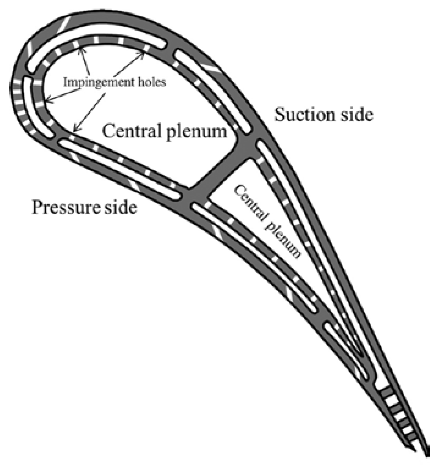
  • Heat transfer enhancement of the wall’s jet region with poor heat transfer performance without considering the influence of the cross flow, as this will be weak in double-wall blades.
  • An AM cooling structure, making maximum use of features that can very accurately determine the positional relationship between impingement nozzles and heat transfer enhancement ribs.
Based on the above-mentioned considerations, circular ribs and vortex generators (VG) were installed in the wall-jet region of single-hole impingement cooling in this study and the heat transfer enhancement in the wall-jet region was investigated. Circular ribs are one method of promoting heat transfer utilizing the forced separation on the top of the rib and reattachment of the flow. The heat transfer coefficient of the reattachment point, where a new boundary layer starts, is very high. The VG utilizes another effect, namely the heat transfer enhancement induced by the strong shear flow due to the generated secondary flow.

2. Experimental Method

The distribution of the heat transfer coefficient on the target plate by the impingement jet from the single circular nozzle was measured using the naphthalene sublimation method. A schematic of the experimental apparatus used for the heat transfer experiment is shown in Figure 2. Dry air was supplied from a compressor into the test section through a heat exchanger, a mass flow controller, and a pressure gauge. The test section has an entrance section with a mesh screen followed by a contraction section to realize a uniform flow upstream of the impingement jet cooling. The air flows out from a single-hole impingement nozzle. Water at a constant temperature of 20 °C, supplied from a constant temperature water circulation device, flows to the heat exchanger and the temperature of the cooling air is thus maintained at 20 °C during the experiment.
A target plate is placed at a certain distance to the impingement nozzle. The cooling air supply part containing the nozzle is movable so as to change this distance. The nozzle plate and the target plate are parallel, and the cooling air impinges on the center of the target plate and subsequently flows out of the test section from all sides. The nozzle diameter D = 32 mm, the exit of which is orifice shaped with an L/D ratio of approximately unity. The distance between the nozzle and the target plate is H/D = 3. The target plate is made of acryl and has a square shape with sides of 400 mm each. A part of the target plate was cut out and a naphthalene container made of aluminum and measuring 230 × 70 mm was attached so as to be level with the target plate surface. The area of the naphthalene within the container covers 210 × 50 mm, and the naphthalene that was cast into the container was carefully checked to ensure a fully smooth transition to the surrounding acrylic surface. Two thermocouples are embedded in the aluminum container to record the temperature of the naphthalene during the test.
Table 1 shows the dimensions of the circular rib used to enhance the heat transfer by detaching and reattaching the boundary layer flow in the wall jet region. The ribs are of square cross section, and three rib heights e/δ = 0.58, 1.0, 1.42 were prepared with a constant circular rib radius of r/D = 3.5. A second set of tests had the goal of setting the rib height to be the same as the boundary layer thickness δ at the position where the circular rib is installed. In this case, heat transfer tests to investigate the effect of the rib location were conducted using five kinds of circular ribs at r/D = 1.6, 2.0, 2.2, 2.5, 3.5 and 4.5. These all maintained the ratio of the rib height e and the boundary layer thickness e/δ = 1.0.
Figure 3 shows the circular ribs and the VG used to enhance heat transfer by attaching them to the wall jet region. The VGs’ dimensions are listed in Table 2. As shown in Figure 4, 12 VGs were arranged radially in a 30° interval on the target plate around the stagnation point of the impingement jet.

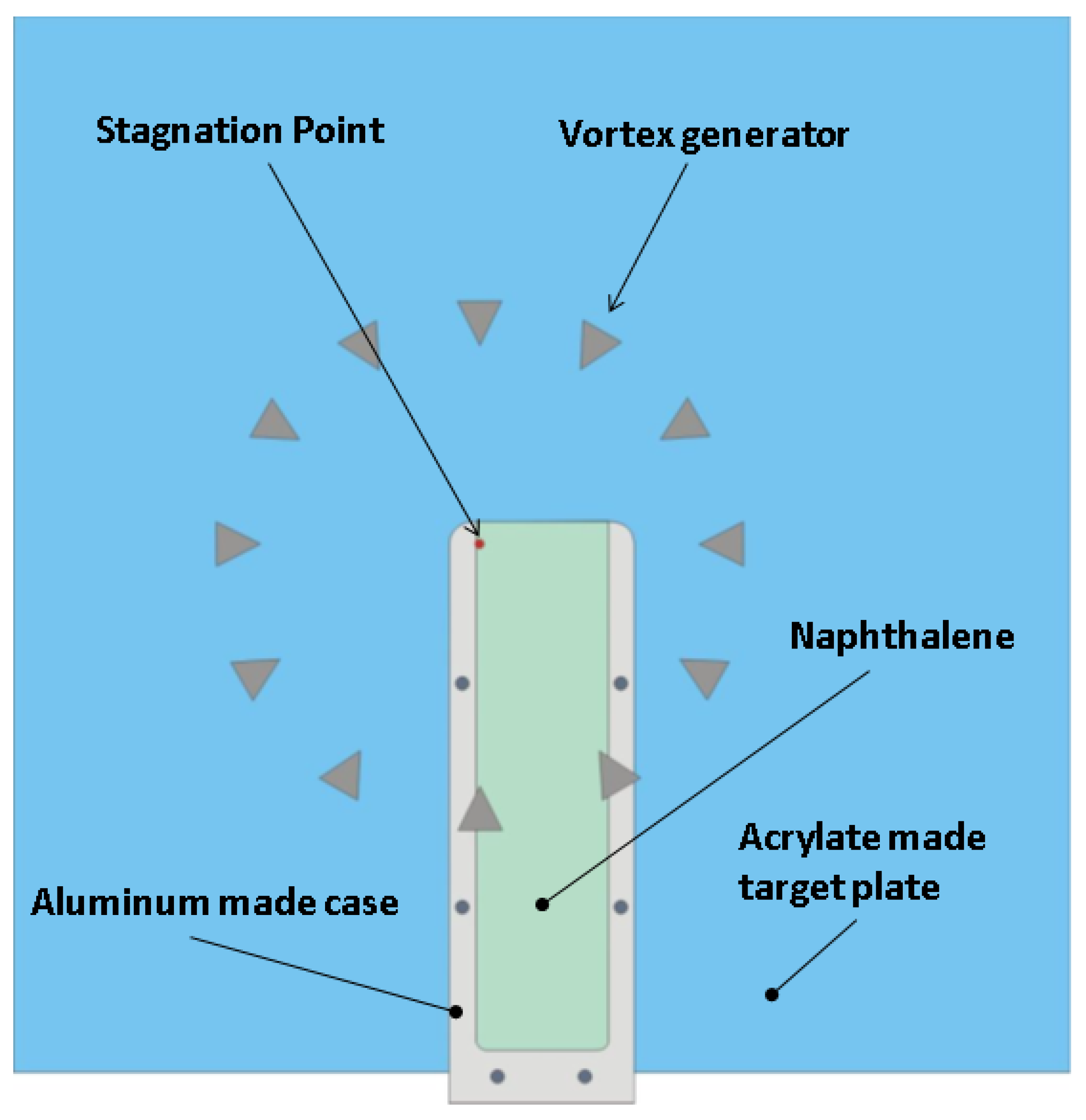
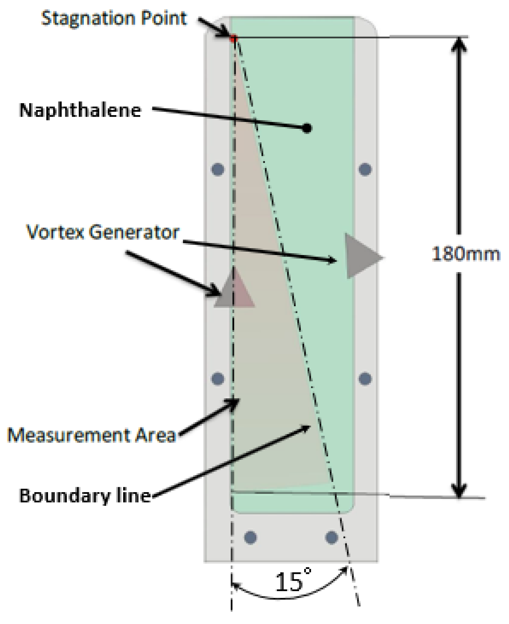
Naphthalene Sublimation Method

The initial surface profile of the naphthalene was scanned using two-axis auto-traverse equipment with a resolution of 1 μm and a laser displacement sensor, which has a measurement depth of focus ±1 mm with a resolution of 0.1 μm and a linearity error of 0.3%. After the test, in which air was blown onto the surface for 40 to 120 min, the surface profile was scanned again. The duration of the test depended on the fluid temperature and flow velocity in order to keep the sublimation depth less than 100 μm. Then, the local naphthalene sublimation depth was calculated as the local change of the surface position from the initial values.
The local mass transfer coefficient was calculated from the following relation:
hd = (RTw/pw)·(ρsδz/te)
The thermo-physical properties of naphthalene were obtained from [17]. The local mass transfer coefficient can be converted to the local heat transfer coefficient by using the analogy between heat and mass transfer.
h = hdρCp(Sc/Pr)1−n
where n is an empirical constant which is 0.4 in this experiment. This value is in line with [2], who take n as 0.42 for the whole region of interest when using naphthalene sublimation, and [9], who state that 0.4 is the correct value for the area between the impingement point and the first rib.
Using the partial derivative method described by [18], an uncertainty analysis was performed on the measured values of the local heat transfer coefficient h based on the uncertainties associated with the measured depth of the naphthalene sublimation, its temperatures, the flow rate and operation time. The precision uncertainties of the naphthalene sublimation depth measured by the laser displacement sensing system, the temperature measured by K-type thermocouples, the flow rate measured by a mass flow controller, and the total operation time were ±0.3%, ±0.1 °C, ±0.8%, and ±5 s, respectively. Combining these uncertainties, the total uncertainty of the local heat transfer coefficient, δh, was found to be 5.5–8.3% over a ReD range of 10,000–70,000.
The area-averaged Nu is calculated by integrating the local Nu distribution.

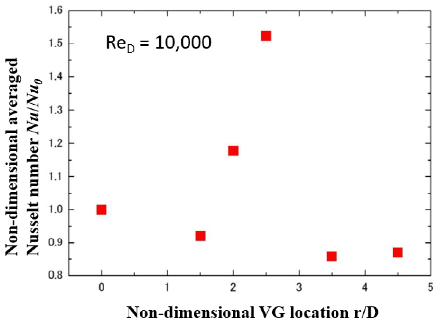
3. Results and Discussion

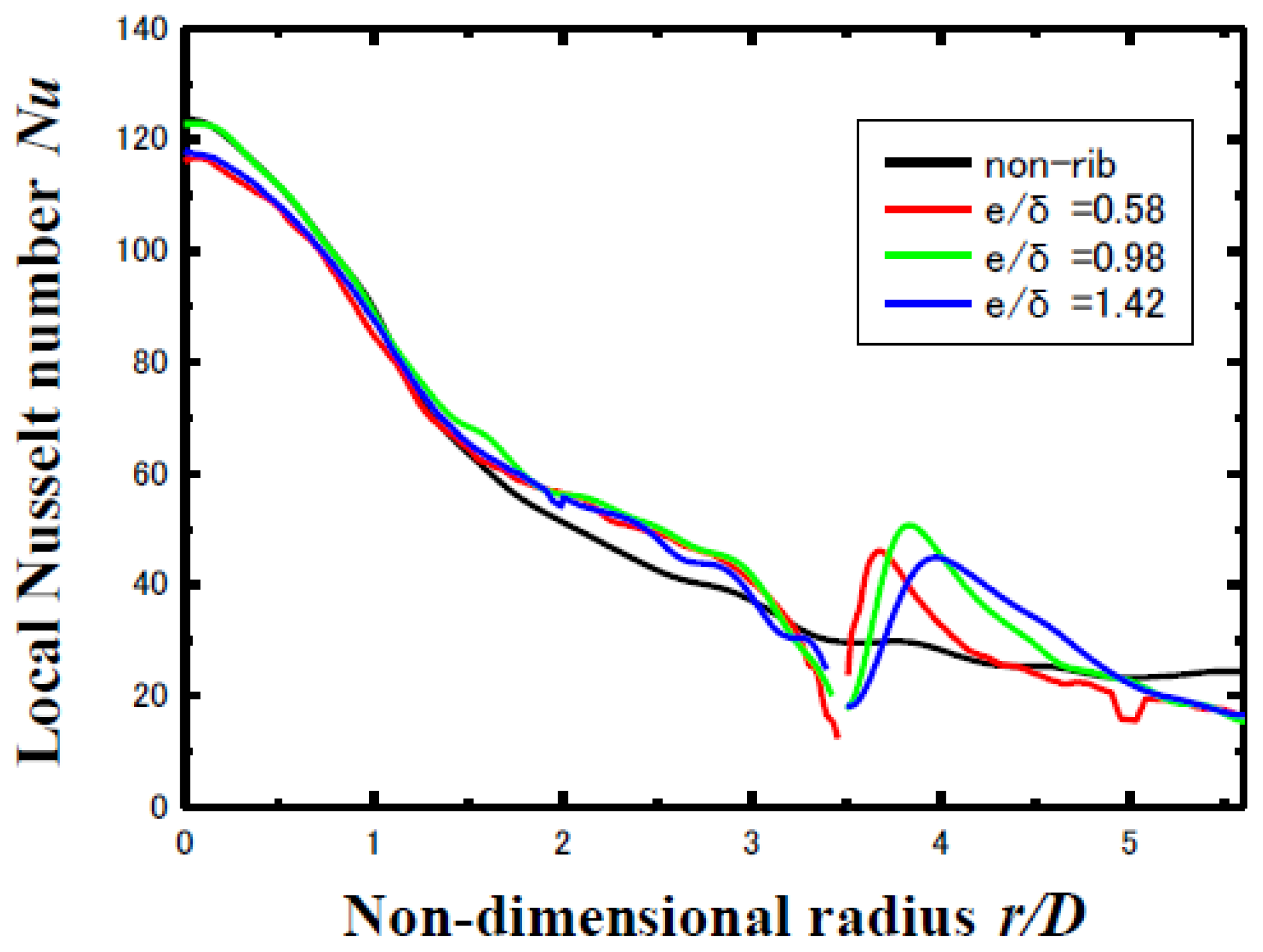
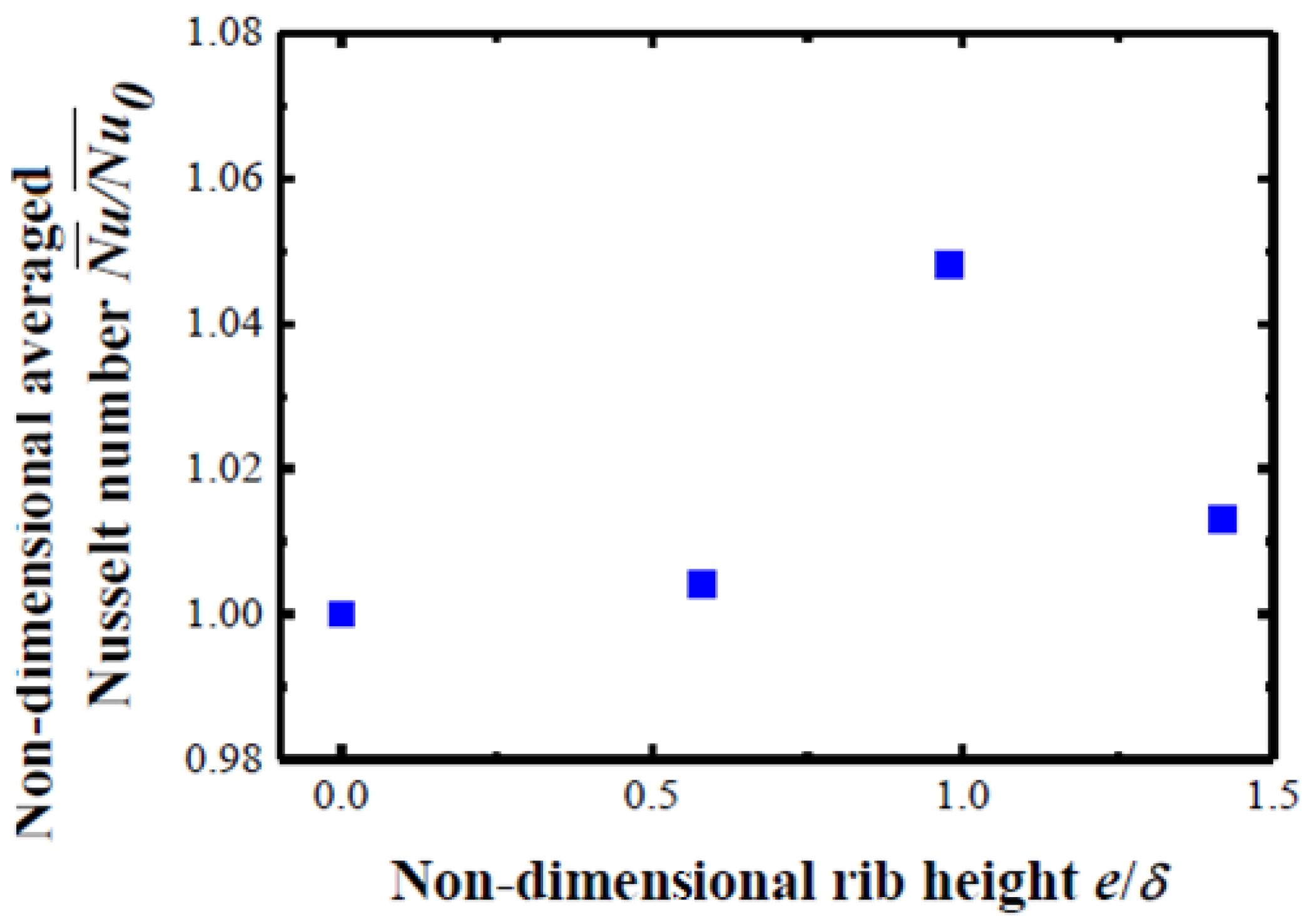
3.1. Effect of the Height of the Circular Ribs on the Enhancement of Heat Transfer

The boundary layer thickness δ in the wall jet region of a circular single jet was measured by a hot wire and empirical Equation (3) established using the measured data.
δ = 0.02r
At location r/D = 3.5, heat transfer experiments were conducted by changing the height of the circular rib between e/δ = 0.58, 1.0 and 1.42. The experimental conditions are shown in Table 3.
Figure 5 shows the results of the measurement of the local Nu distribution in radial direction using the naphthalene sublimation method under the aforementioned experimental conditions. Figure 6 shows the area-averaged Nu integrated over the whole area of 0 ≦ r/D ≦ 5.6 with the dimensionless rib height as the parameter on the x-axis. The y-axis is normalized by Nu0 of the configuration without a circular rib. As shown in Figure 6, when the value of the rib height e of the circular rib is about the same as the boundary layer thickness δ at the position where the rib is located, the area-averaged Nu reaches its maximum value. This is in line with experiments on impingement jets using two-dimensional nozzles conducted prior to the current research [4]. These were also confirmed by LES and DNS calculations [9]. This is, thus, when the flow rate which is blocked by the front face of the rib is smallest. A forced separation flow on the top of the rib is generated on the upper face of the rib at the outer edge of the boundary layer where the maximum flow velocity is reached. A high heat transfer coefficient on the target plate is achieved near the reattachment point, where a strong shear flow is generated.

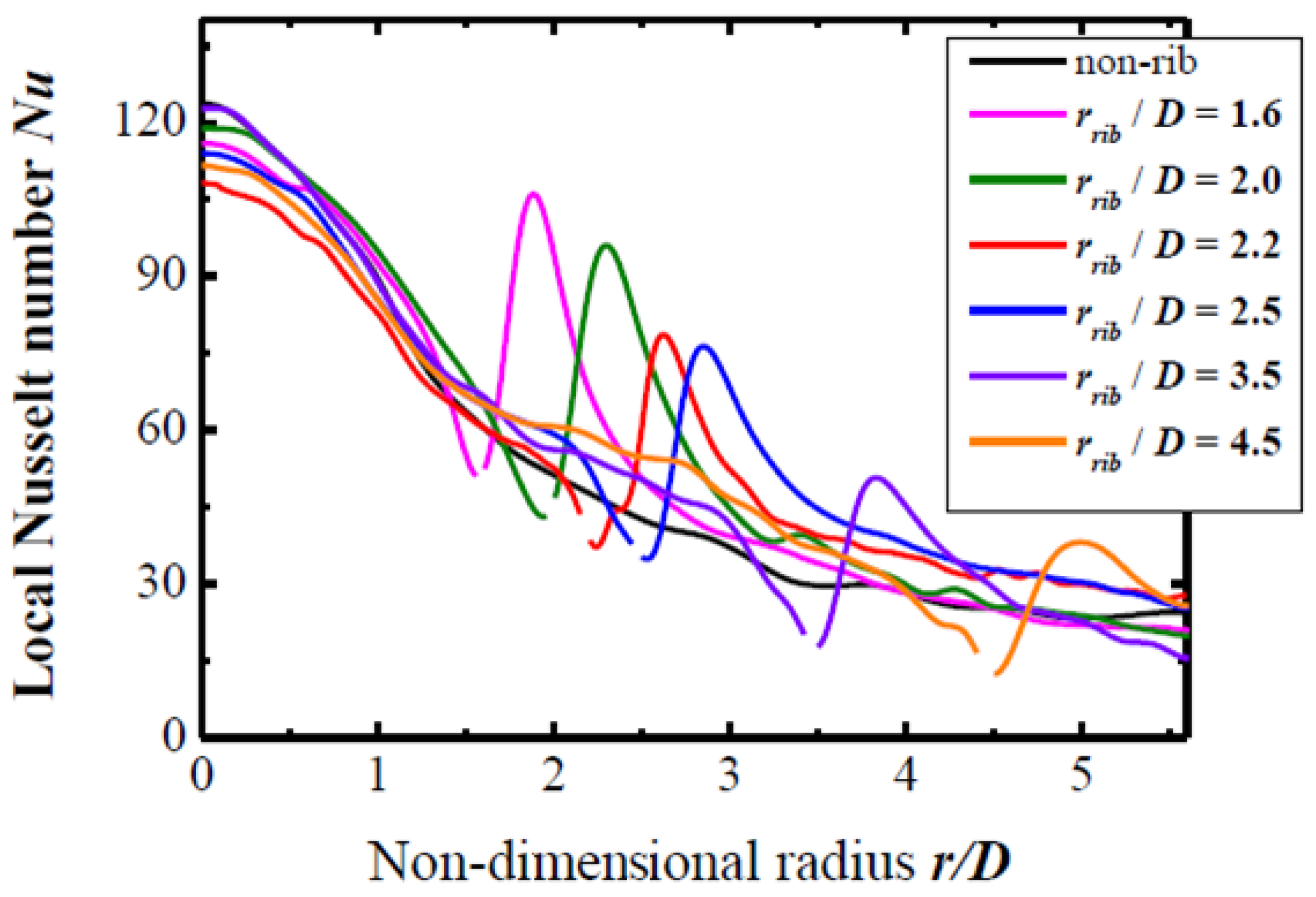
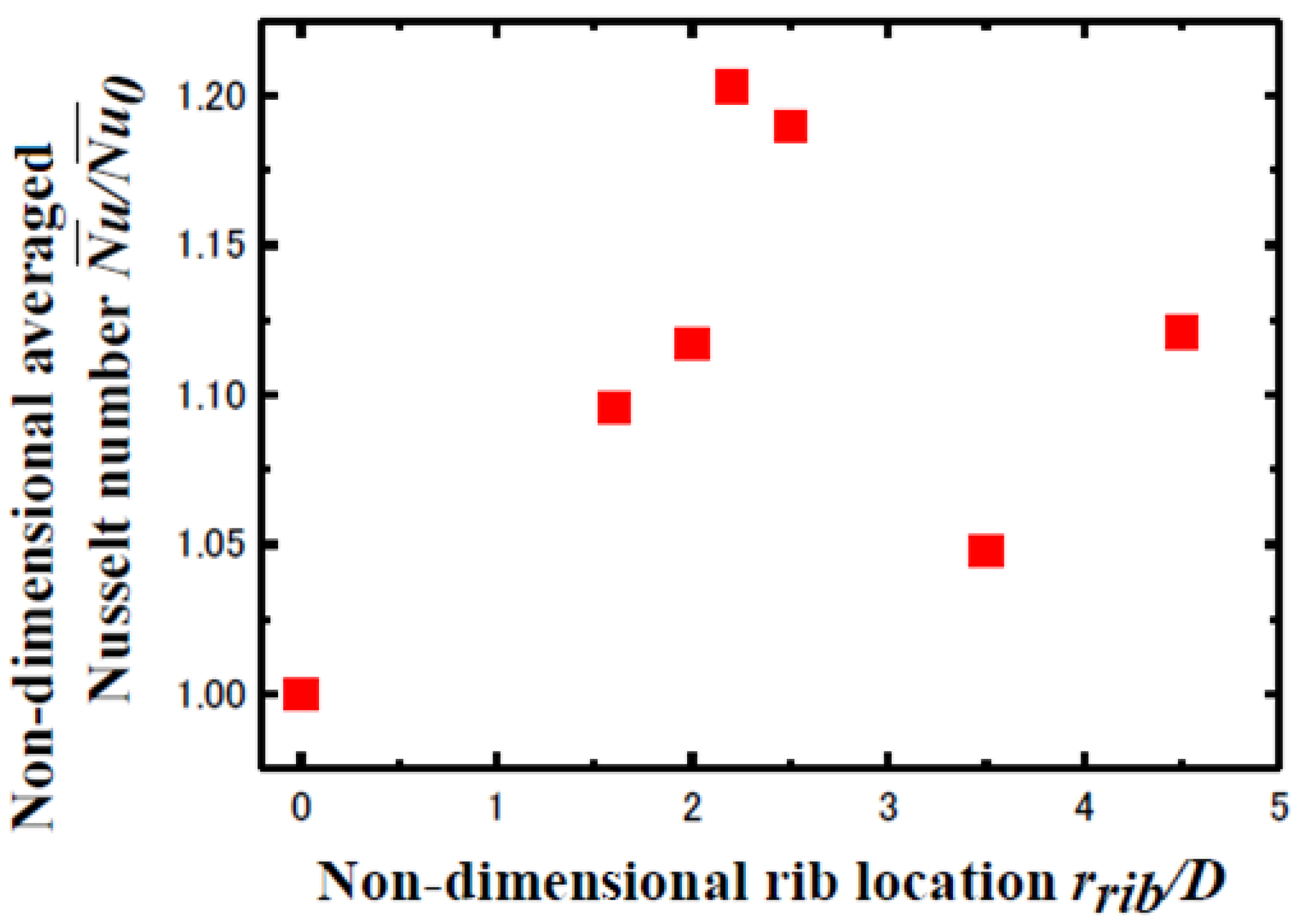
3.2. Effect of Circular Rib Location on Heat Transfer Enhancement

In the previous section it was shown that the area-averaged Nu attains its maximum when the rib height e of the circular rib coincides with the boundary layer thickness δ at the position of the rib. Based on this result experiments were conducted that aimed at influencing the local heat transfer coefficient by changing the position at which the circular rib was installed. At every radius, the rib height e was equal to the boundary layer thickness δ at the point of installation. Table 4 shows the experimental conditions for this set-up.
Figure 7 shows the distribution of the local Nu number that can be achieved by changing the position of the circular rib with a rib height optimized according to the insights mentioned previously. The naphthalene sublimation method was used again. Although the values for heat transfer enhancement of the ribs just before and just after r/D ≈ 2 fall within the experimental uncertainty, the substantial difference in enhancement after r/D ≈ 2 is well beyond this.
Figure 8 shows the results of the calculation of the area-averaged Nu by integrating the measured local Nu distribution over 0 ≦ r/D ≦ 5.6. It can be seen from Figure 8 that the area-averaged Nu attains a local maximum near r/D = 2. From Figure 7 it may seem that the local Nu reached its maximum when the position of the circular rib is closer to the stagnation point at r/D = 1.6. However, when the area-averaged Nu is calculated taking the weighted annular area at which the various local Nu are achieved into account, as shown in Figure 8, the maximum Nu is reached near r/D = 2.2. The area-averaged Nu tends to increase with increasing r/D again after a sharp drop immediately after the maximum value around r/D = 2.2. The reason that the area-averaged Nu at r/D = 4.5 is larger than at r/D = 3.5 is that, although the local Nu at the reattachment point is lower for the former than for latter position, the annular area at r/D = 4.5 is much larger.

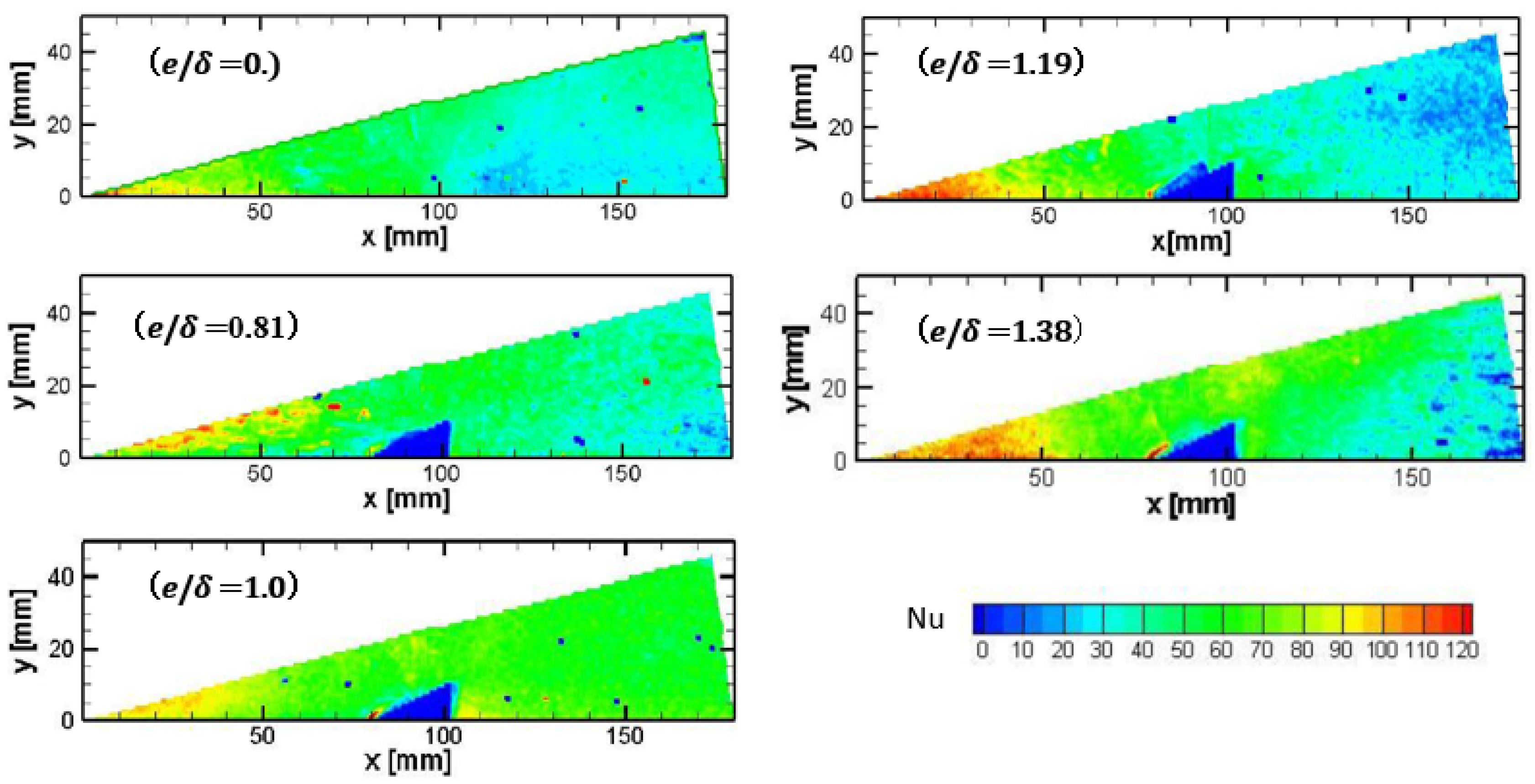
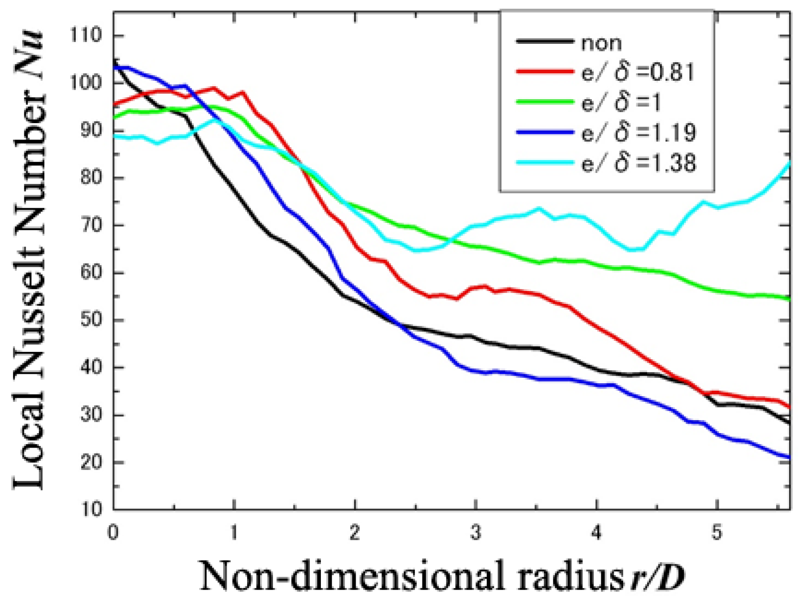
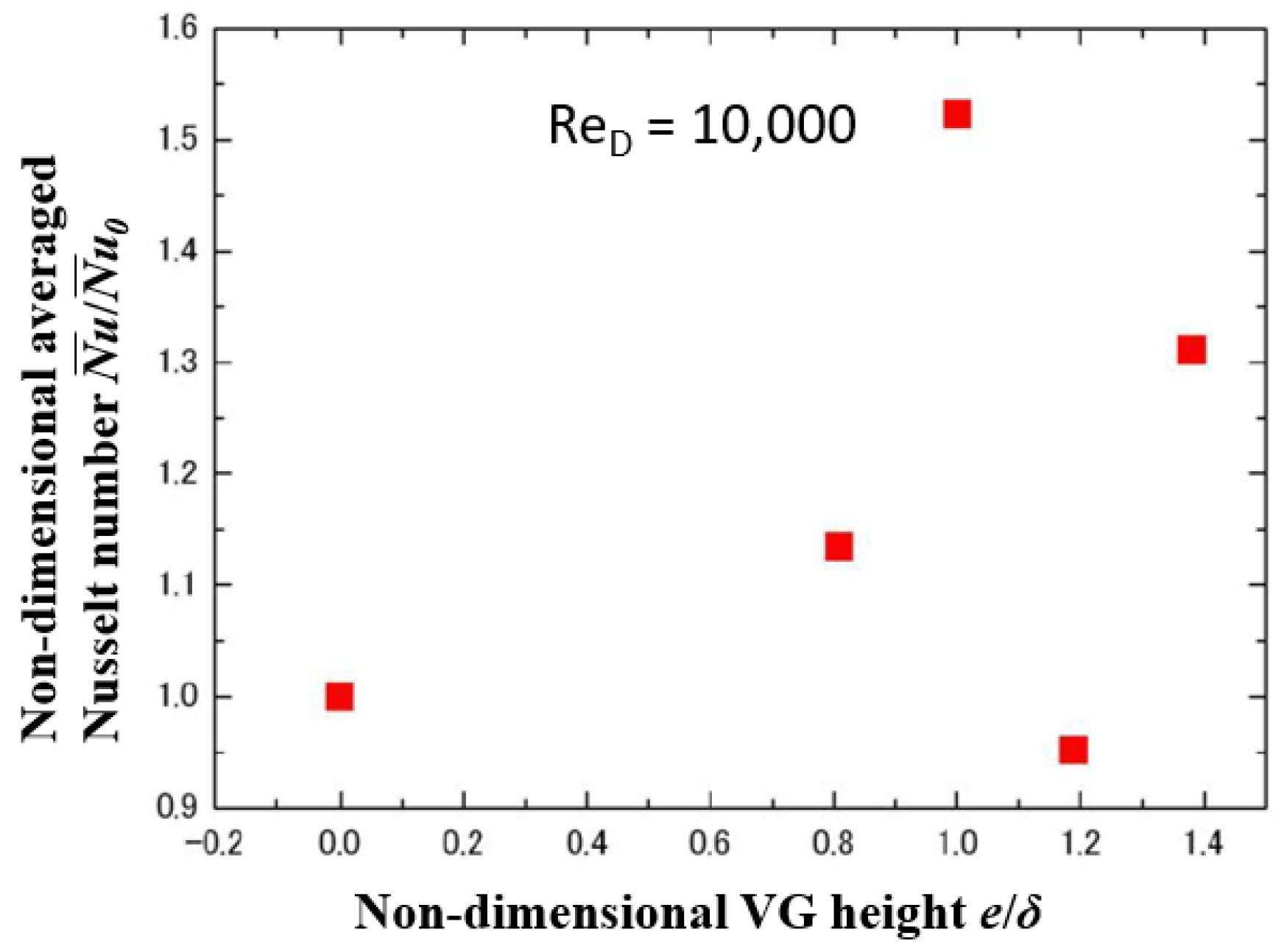
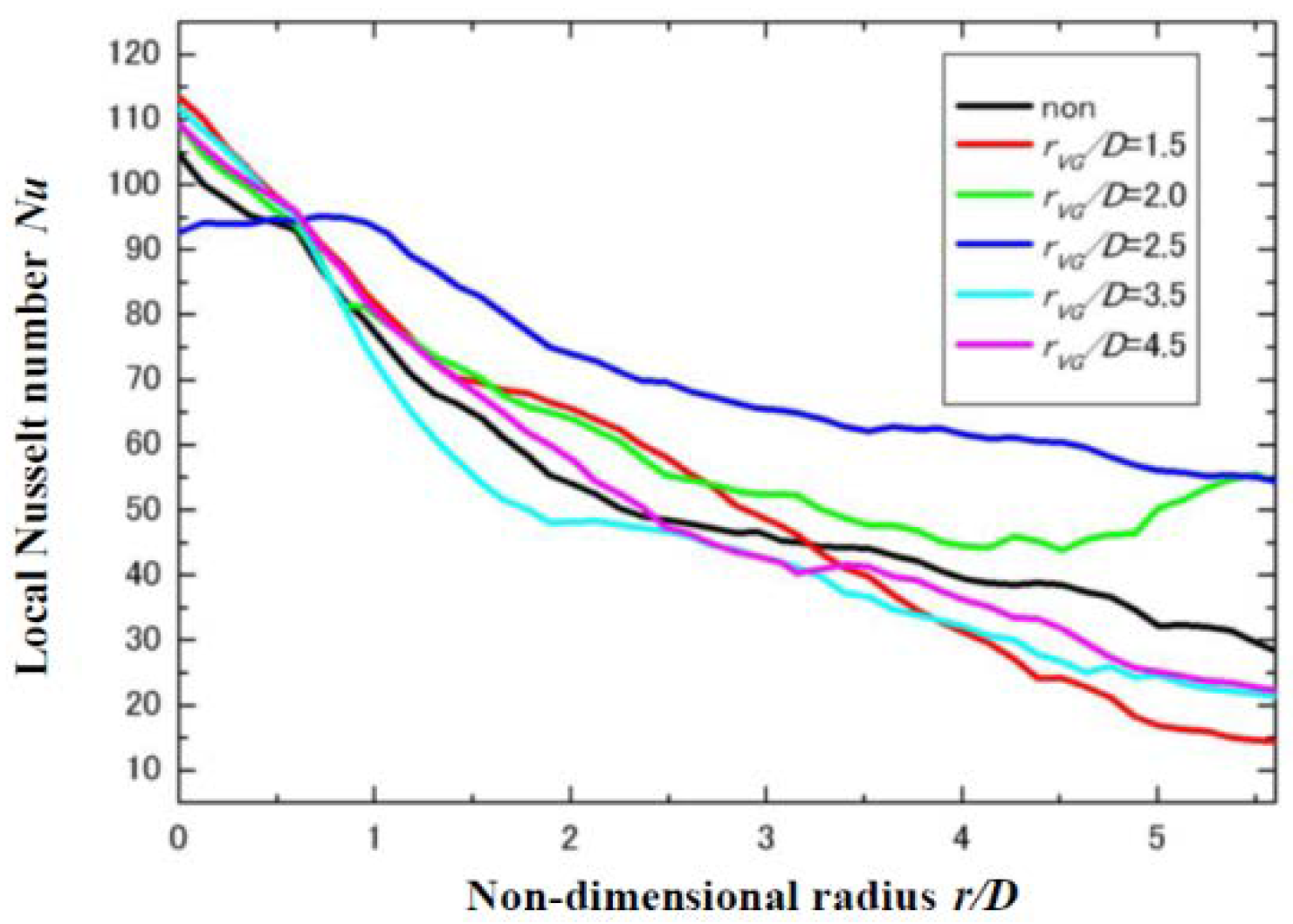
3.3. Effect of VG on the Enhancement of Heat Transfer

As shown in Figure 4, this experiment was carried out by locating 12 VGs at intervals of 30 degrees at a certain radius around the stagnation point. Figure 9 shows the locations in the set-up where the naphthalene substrate and VG for measuring the local heat transfer coefficient distribution are installed. This measurement was conducted within the fan shaped area of 0° to 15° indicated in Figure 9.
In addition to investigating the influence of the rib height of the circular rib on heat transfer, the influence of the height of the VG on the heat transfer was investigated. Table 5 shows the experimental conditions aimed at examining this influence. In the experiment using a VG with a shape as shown in Figure 3, the local heat transfer coefficient is measured by the naphthalene sublimation method. The ratio e/δ with the boundary layer thickness δ at the position where the VG is installed, and the height e of the VG were used to define the dimensionless height of the ribs.
The area-averaged Nu was calculated from the integration of the local Nu. Figure 10 shows the distribution of the latter with e/δ = 0 (i.e., no VG) to 1.38 at r/D = 2.5. The distribution of the local Nu measured along the boundary line between the VGs shown in Figure 9 is depicted in Figure 11. Furthermore, the area-averaged Nu was calculated over 0° to 15° at r/D = 0 to 5.63, i.e., the whole measurement area in Figure 9, and this result is shown in Figure 12.
It can be concluded from Figure 10 that heat transfer is promoted by the vortex flow generated by the VG. Since this is a three-dimensional flow, the trend of the Nu boundary line between the VGs cannot be predicted. However, it is clear that heat transfer was promoted by the VG installed at r/D = 2.5. Although this effect is confirmed at e/δ = 1.0, the effect of the VG is not as good at e/δ = 1.19. Surprisingly, a high heat transfer enhancement was again observed at e/δ = 1.38. It is assumed that for e/δ = 1.19 the swirling flow generated by the VG does not come into contact with the target plate and, thus, it does not lead to an enhancement by reattachment to the target plate.
As shown in Figure 12, when e/δ = 1.0 the area-averaged Nu reaches its maximum. Therefore, the influence of the VG on the local heat transfer coefficient was investigated using the installation position of the VG as a parameter while keeping the height e of the VG at the installation position at e/δ = 1.0. Table 5 shows the experimental conditions for investigating the influence of the position of the VG on local Nu. Figure 13 shows the results for the distribution of local Nu on the boundary line between the VGs. The ratio of Nu/Nu0 is shown in Figure 14. Again, Nu is integrated from the local Nu distribution with θ = 0° to 15°, r/D = 0 to 5.63, and Nu0 is the area-averaged value in the same region to which no VG is added. It is difficult to determine the exact location of r/D where Nu/Nu0 reaches its maximum value because of the small amount of data, but from Figure 14 it is obvious that, when the position of the VG is near r/D = 2.5, the area-averaged Nu reaches a local maximum. This tendency is the same as Nu/Nu0 reaching its maximum near r/D = 2.2 when using the position as a parameter for the circular rib, as shown in Figure 8.

4. Conclusions

A study aimed at enhancing heat transfer in the wall jet region of impingement cooling suitable for adoption in future double wall airfoils was conducted. The local heat transfer coefficient distribution was measured using the naphthalene sublimation method. The following conclusions can be drawn from the investigation of the heat transfer enhancement effect of circular ribs or VG in the wall jet region of such jets.
  • If the rib height e of a circular rib is set to be approximately the same as the boundary layer thickness δ, the heat transfer coefficient reaches a maximum.
  • A rib with a height approximately equal to the boundary layer thickness and at the position r/D = 2.2 leads to a local maximum value of the averaged Nu.
  • When VGs are arranged radially around the stagnation point and heat transfer enhancement is investigated by changing their height, then the configuration with e/δ = 1.0 and r/D = 2.5 achieves a global maximum. This trend is similar to that of the circular ribs.
  • It was possible to improve the area-averaged Nu with up to 21% for circular ribs and up to 51% for VGs within the range of the experiments. Although VG may have little effect in some cases, with the right set of parameters they constitute a means of effective heat transfer enhancement.
  • For future impingement cooling structures that can be manufactured using AM, the positional relationship between the impingement nozzle and features such as the heat transfer enhancement ribs on the target surface can be controlled very accurately. The research discussed in this study provides a very useful way of thinking of new designs for impingement cooling for AM geometries such as double wall airfoils.

Author Contributions

Conceptualization and methodology, K.-I.T.; validation, K.-I.T., and Y.O.; formal analysis, K.-I.T., R.K., Y.O. and Y.I.; investigation, Y.O. and Y.I.; resources, K.-I.T.; data curation, Y.I.; writing—original draft preparation, T.K., R.K.; writing—review and editing, R.K.; visualization, R.K.; supervision, K.-I.T.; project administration, K.-I.T.; funding acquisition, K.-I.T. All authors have read and agreed to the published version of the manuscript.

Funding

This research received no external funding.

Conflicts of Interest

The authors declare no conflict of interest.

Nomenclature

erib height [mm]
hheat transfer coefficient [W/(m2·K)]
hDmass transfer coefficient [m/s]
pwsaturated vapour pressure [Pa]
rdistance from stagnation point [mm]
rribradius of a circular-rib [mm]
teexperimental time [s]
x, y, zcoordinates [mm]
Cpspecific heat [kJ/(kg·K)]
Dnozzle diameter [mm]
Hdistance between nozzle and target plate [mm]
Twwall temperature [K]
Rgas constant of naphthalene [kJ/(kg·K)]
NuNusselt number [-]
PrPrandtl number [-]
ReReynolds number based on D [-]
ScSchmidt number [-]
δboundary layer thickness [mm]
δznaphthalene sublimation thickness [mm]
λthermal conductivity [W/(k·K)]
θazimuth [degrees]
ρdensity of air [kg/m3]
ρsdensity of naphthalene [kg/m3]

References

  1. Hada, S.; Yuri, M.; Masada, J.; Ito, E.; Tsukagoshi, K. Evolution and Future Trend of Large Frame Gas Turbines—A New 1600 Degree C, J Class Gas Turbine. In Proceedings of the ASME Expo 2012, Copenhagen, Denmark, 11–15 June 2012. Paper No. GT2012-68574. [Google Scholar]
  2. Schlünder, E.U.; Gnielinski, V. Wärme- und Stoffübertragung zwischen Gut und aufprallendem Düsenstrahl. Chem. Ing. Tech. 1967, 39, 578–584. [Google Scholar] [CrossRef]
  3. Annerfeldt, M.O.; Persson, J.L.; Torisson, T. Experimental Investigation of Impingement Cooling with Turbulators or Surface Enlarging Elements. In Proceedings of the ASME Turbo Expo 2001, New Orleans, LA, USA, 4–7 June 2001. Paper No. 2001-GT-0149. [Google Scholar]
  4. Sugimoto, S.; Takeishi, K.; Oda, Y.; Harada, T. A Study on Heat Transfer Enhancement of Jet Impingement Cooling by Turbulence Promotors. In Proceedings of the 9th International Gas Turbine Congress (IGTC2007), Tokyo, Japan, 2–7 December 2007. TS-116. [Google Scholar]
  5. Haiping, C.; Dalin, Z.; Taiping, H. Impingement Heat Transfer from Rib Roughened Surface within Arrays of Circular Jets: The Effect of the Relative Position of the Jet Hole to the Ribs. In Proceedings of the ASME Expo 1997, Orlando, FL, USA, 2–5 June 1997. Paper No. 97-GT-331. [Google Scholar]
  6. Son, C.; Dailey, G.; Ireland, P.; Gillespie, D. An Investigation of the Application of Roughness Elements to Enhance Heat Transfer in an Impingement Cooling System. In Proceedings of the ASME Turbo Expo 2005, Reno, NV, USA, 6–9 June 2005. Paper No. GT2005-68504. [Google Scholar]
  7. Spring, S.; Xing, Y.; Weigand, B. An Experimental and Numerical Study of Heat Transfer from Arrays of Impinging Jets with Surface Ribs. ASME J. Heat Transf. 2012, 134, 082201-1. [Google Scholar] [CrossRef]
  8. Trabold, T.A.; Obot, N.T. Impingement Heat Transfer within Arrays of Circular Jets. Part II: Effects of Crossflow in the Presence of Roughness Element. In Proceedings of the International Gas Turbine & Aeroengine Congress & Exhibition, Anaheim, CA, USA, 31 May–4 June 1987. Paper No. 87-GT-200. [Google Scholar]
  9. Oda, Y.; Takeishi, K. Concurrent Large-Eddy Simulation of Wall-Jet Heat Transfer Enhanced by Systematically-Deformed Turbulence Promoter. In Proceedings of the 15th International Heat Transfer Conference (IHTC-15), Kyoto, Japan, 10–15 August 2014. [Google Scholar]
  10. Lutum, E.; Semmler, K.; von Wolfersdorf, J. Cooled Blade for a Gas Turbine. U.S. Patent 2001/0016162 A1, 23 August 2001. [Google Scholar]
  11. Dailey, G.M.; Evans, P.A.; McCall, R.A.B. Cooled Aerofoil for a Gas Turbine Engine. European Patent EP 1 022 432 B1, 23 March 2005. [Google Scholar]
  12. Liang, G. Turbine Airfoil with Multiple Near Wall Compartment Cooling. U.S. Patent 7,556,476 B1, 7 July 2009. [Google Scholar]
  13. Liang, G. Stator Vane with Near Wall Integrated Micro Cooling Channels. U.S. Patent 8,414,263 B1, 9 April 2013. [Google Scholar]
  14. Terzis, A.; Cochet, M.; von Wolfersdorf, J.; Weigand, B.; Ott, P. Detailed Heat Transfer Distributions of Narrow Impingement Channels with Varying Jet Diameter. In Proceedings of the ASME Turbo Expo 2014, Düsseldorf, Germany, 16–20 June 2014. Paper No. GT2014-25910. [Google Scholar]
  15. Stoakes, P.; Ekkad, S. Optimized Impingement Configurations for Double Wall Cooling Applications. In Proceedings of the ASME Turbo Expo 2011, Vancouver, BC, Canada, 6–10 June 2011. Paper No. GT2011-46143. [Google Scholar]
  16. Li, W.; Li, X.; Ren, J.; Jiang, H. A Novel Method for Designing Fan-Shaped Holes With Short Length-to-Diameter Ratio in Producing High Film Cooling Performance for Thin-Wall Turbine Airfoil. J. Turbomach. 2018, 140, 091004. [Google Scholar] [CrossRef]
  17. Goldstein, R.J.; Cho, H.H. A Review of Mass Transfer Measurements Using Naphthalene Sublimation. Exp. Therm. Fluid Sci. 1995, 10, 416–434. [Google Scholar] [CrossRef]
  18. Moffat, R.J. Describing the Uncertainties in Experimental Results. Exp. Therm. Fluid Sci. 1988, 1, 3–17. [Google Scholar] [CrossRef] [Green Version]
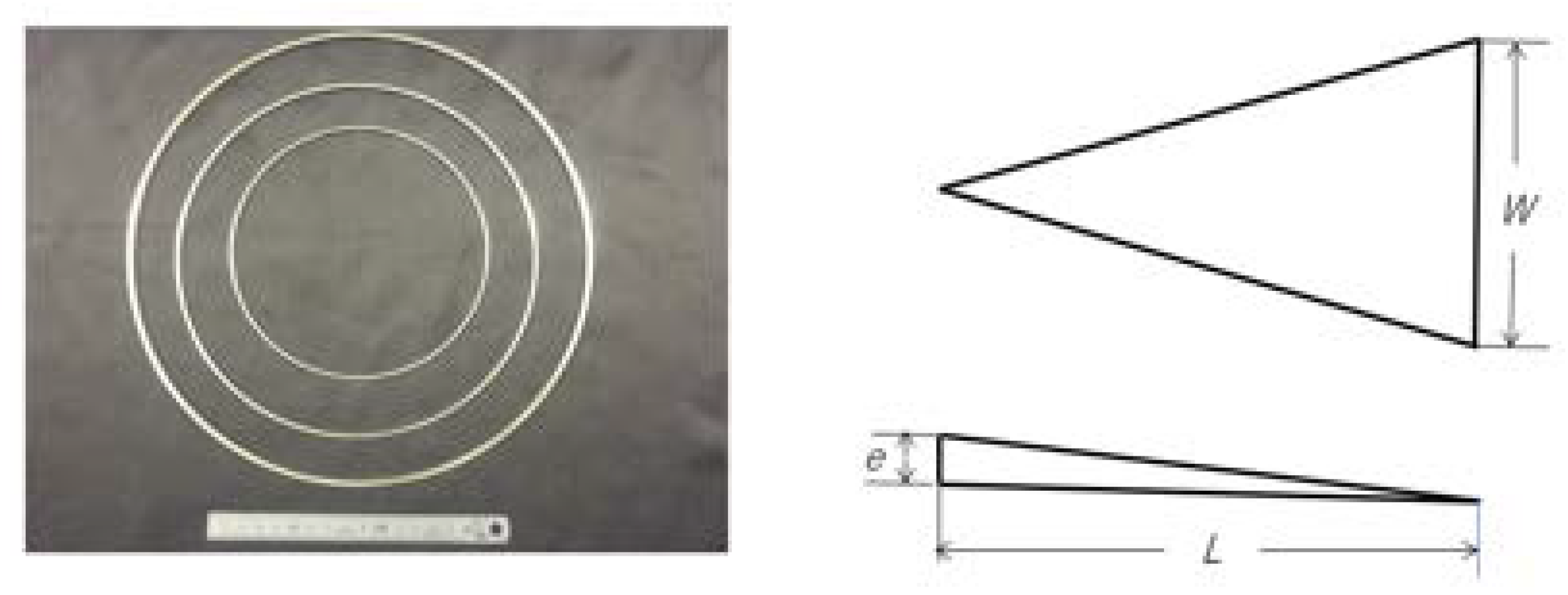
Figure 1. Double wall cooling vane from [16].
Ijtpp 05 00017 g001
Figure 2. Experimental apparatus.
Ijtpp 05 00017 g002
Figure 3. Circular ribs and vortex generator.
Ijtpp 05 00017 g003
Figure 4. Layout of VGs on the target plate.
Ijtpp 05 00017 g004
Figure 5. Effect of circular rib height on the local Nu at r/D = 3.5.
Ijtpp 05 00017 g005
Figure 6. Effect of circular rib height on the averaged Nu (at the fixed circular rib location of r/D = 3.5).
Ijtpp 05 00017 g006
Figure 7. Effect of the circular rib locations on local Nu (at the fixed circular rib height of e/δ = 1.0).
Ijtpp 05 00017 g007
Figure 8. Effect of circular rib location on the averaged Nu (at the fixed circular rib height of e/δ = 1.0).
Ijtpp 05 00017 g008
Figure 9. Location of VGs on the naphthalene target plate.
Ijtpp 05 00017 g009
Figure 10. Effect of VG height on the Nu distribution (at the fixed VG location r/D = 2.5, ReD = 10,000).
Ijtpp 05 00017 g010
Figure 11. Effect of VG height on the local Nu distribution along boundary line in Figure 9 (fixed VG location: r/D = 2.5).
Ijtpp 05 00017 g011
Figure 12. Effect of VG height on the averaged Nu (fixed VG location: r/D = 2.5).
Ijtpp 05 00017 g012
Figure 13. Effect of VG location on the local Nu distribution along boundary line in Figure 9 (fixed VG height: e/δ = 1.0).
Ijtpp 05 00017 g013
Figure 14. Effect of VG location on the averaged Nu (fixed VG height: e/δ = 1.0).
Ijtpp 05 00017 g014
Table 1. Dimensions of circular ribs.
Radius of Ribs rrib
(rrib/D)
Rib Height e
(e/δ)
51.2 mm (1.6)1.0 mm (=1)
61.4 mm (2.0)1.3 mm (=1)
70.4 mm (2.2)1.4 mm (=1)
89.0 mm (2.5)1.6 mm (=1)
112 mm (3.5)1.3 mm (=0.58)
2.2 mm (=1)
3.2 mm (=1.42)
144 mm (4.5)2.9 mm (=1)
Table 2. Dimensions of VGs.
Length L
[mm]
Width W
[mm]
Height e
[mm]
22221.0
1.3
1.6
1.9
2.2
2.9
Table 3. Experimental conditions of circular ribs.
Reynolds Number Re10,000
Distance H/D3.0
Boundary layer thickness δ2.0
Location of circular ring r/D3.5
Height of circular rings e/δ0.58, 0.98, 1.42
Table 4. Experimental conditions for locations of circular ribs.
Reynolds Number Re10,000
Distance H/D3.0
Boundary layer thickness δ2.0
Location of circular ring r/D1.6, 2.0, 2.2, 2.5, 3.5, 4.5
Height of circular rings e/δ1.0
Table 5. Experimental conditions for locations of VG.
Reynolds Number Re10,000
Distance H/D32.0
Boundary layer thickness δ3.0
Location of VG’s r/D1.5, 2.0, 2.5, 3.5, 4.5
Height of VG’s e/δ1.0

