1. Introduction
Decades of research in the topic of hot gas ingestion point towards disc pumping, circumferential annulus pressure asymmetries and, more recently, rim seal flow instabilities as the main drivers for hot gas ingestion. These three mechanisms are depicted in
Figure 1. Ingress of high temperature flow from the main gas path is undesired. Rotor discs are not thermally insulated and the ingestion of hot gas from the mainstream can significantly damage the mechanical integrity of these highly stressed components and reduce their operating life. To prevent this from occurring, cool air is injected between the stator and rotor discs to purge and pressurise the cavity. However, this comes at the detriment of engine efficiency. The intrinsically convoluted flow field in the turbine rim region creates a complex environment in which fundamental understanding of the basic flow physics becomes paramount to comprehend the synergetic effect of each of the mechanisms mentioned above. This investigation focuses on the performance of a chute rim seal with no blades and vanes in the annulus, such that ingestion is expected to be driven by the effects of rotation. Bru Revert et al. [
1] showed that this scenario is relevant for high pressure turbines at low flow coefficients.
The spacing between the stator ring and the rotor disc is sufficient to allow for separate boundary layers and turbulent flow to develop in the cavity as established by Daily and Nece [
2]. Shear forces transfer angular momentum from the rotating disc to the adjacent fluid and the centrifugal force then projects the flow radially out towards the rim gap. The purge flow introduced in the inner region of the cavity feeds the boundary layer on the rotor disc. A core of rotating inviscid flow develops in the cavity volume inducing a pressure gradient that leads to lower pressures in the cavity than in the annulus. The flow structure inside the cavity volume is influenced by the ingress and egress of flow through the rim seal. To balance any excess of egress over the supplied purge flow rate, mainstream flow from the outside environment may be drawn into the cavity through the rim seal. After mixing with purge flow in the outer part of the cavity, ingressed flow entrains the boundary layer on the stator disc and progresses radially inward. The mixed flow in the stator boundary layer travels axially across the inviscid core to enter the rotor boundary layer.
Initial studies of the disc pumping effect, such as that of Bayley and Owen [
3], derived empirical correlations to quantify the minimum amount of purge flow necessary to fully seal the cavity. With the introduction of the tracer gas technique to study hot gas ingestion, experimental data quantifying sealing effectiveness became available. Several rim seal geometrical arrangements were studied revealing that the radial seal over-performed the axial seal. Chew [
4] developed an orifice model to estimate the sealing effectiveness under dominance of the disc pumping effect. Chew’s correlation could be fitted to different seal geometries by adjusting the empirical constant
k which indicates the ability to prevent ingestion of each rim seal design. The model is detailed in Equation (1), where
Um is the mean flow velocity through the rim seal, Ω is the angular speed and
b is the rotor disc radius.
Further studies simulated more engine-realistic scenarios with pressure asymmetries in the main gas path and showed that the ingestion of annulus flow at the rim seal region could be dominated by rotation or pressure asymmetries, e.g., Phadke and Owen [
5]. Later, advances in computational methods and measurement techniques allowed Cao et al. [
6] to numerically and experimentally identify large scale unsteady flow features in the rim seal cavity that could also dominate ingress of hot gas. Further details of previous work are given in the extensive reviews by Scobie et al. [
7] and Chew et al. [
8].
The results of an investigation of the disc pumping effect in a turbine disc cavity with a chute rim seal arrangement are presented in this paper extending the preliminary study by Bru Revert et al. [
9]. The effect of annulus pressure asymmetries created by the presence of NGVs in the gas path is compared by Bru Revert et al. [
1] to the results of this study. The sealing performance is assessed based on pressure measurements and values of sealing effectiveness derived from readings of gas concentration in the absence of external flow and with an axial axisymmetric annulus flow. The sensitivity of these variables to changes in purge flow, annulus flow, rotor disc speed and seal clearance are discussed.
The experimental configuration of the Oxford Rotor Facility is briefly described first, followed by the discussion of the cavity flow based on steady pressure measurements. Next, the sensitivities of the sealing effectiveness and cavity pressure coefficient to rotor disc speed, purge flow, mainstream flow and seal clearance are thoroughly analysed under different test conditions. A summary of the main findings of the study is given in the concluding section.
2. Experimental Setup
The Oxford Rotor Facility (ORF) was modified to study rim sealing flows and an extensive description of the modifications to the facility was published by Bru Revert et al. [
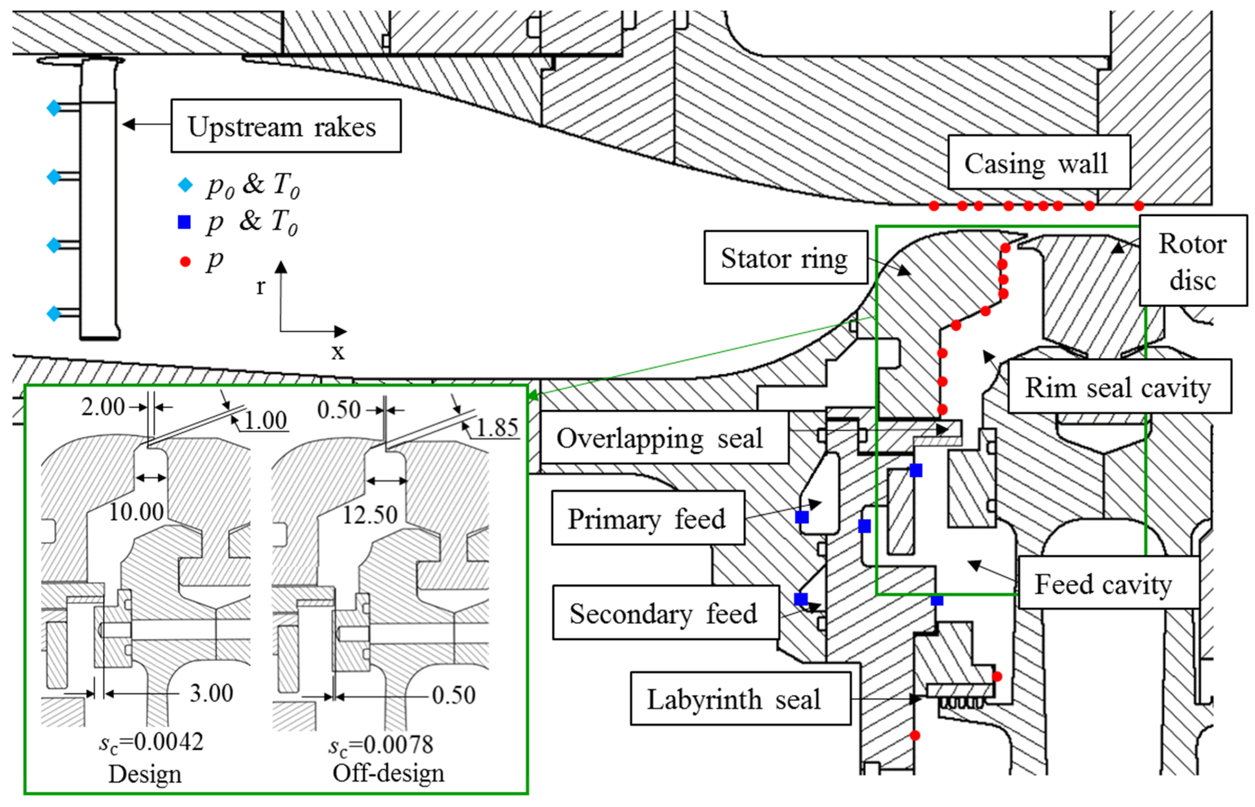
1]. To investigate purely rotationally induced ingestion, the NGVs and rotor blades were not included in the working section and therefore the pressure asymmetries in the annulus were removed. Instead, dummy rotor and stator discs were installed in the facility (see
Figure 2).
A nominal rim gap of 1 mm was studied. This was measured between the stator and rotor surfaces in the angled region of the chute rim seal which corresponded to a 2 mm overlap in the axial direction. An increased seal clearance of 1.85 mm was also studied representing an off-design engine condition in which rear axial displacement of the turbine may occur. The gap increase was achieved by introducing a spacer ring between the shaft and the rotor disc. However, due to the movement of the rotor disc, the overlap was lost and replaced by a 0.5 mm axial displacement. The purge flow was supplied through 60 holes of 2.5 mm diameter in the primary feed with a discourager surface to prevent jetting. A secondary feed was available but was not used.
Pressure and temperature measurements were acquired at strategic points in the working section to monitor the flow conditions as specified in
Figure 2. Temperature measurements were obtained with k-type bare bead thermocouples with exposed tips (uncertainty ±0.45%). Absolute pressures were acquired through First Sensor CTE8000 transducers (uncertainty of ±0.1% of full-scale output), whilst the differential measurements inside the cavity were logged with First Sensor BTEM5000 (±0.2% of full-scale output uncertainty) pressure sensors. Total pressure and total temperature rakes were located upstream of the working section at four circumferential positions to ensure the mainstream flow, when present, was axisymmetric (0.2% maximum deviation from the mean pressure of the four rakes). Likewise, static pressure and total temperature were registered in the purge flow feed system. Pressure taps were distributed radially along the stator wall and were used to log static pressures as well as to sample tracer gas concentration in the cavity. The measurements presented here were recorded at 97° from top dead center in the clockwise direction when looking from downstream. Unsteady pressures were acquired with Kulite
TM XCQ-062 series pressure sensors mounted in the stator wall at equivalent radial positions to those of the steady taps in
Figure 2, with a circumferential offset of 160°. Unsteady pressures were logged for 1 s at a sampling frequency of 1 MHz. The data were filtered after acquisition with a low pass band Butterworth filter.
The tracer gas technique was used to assess the sealing performance of the chute seal. Sample gas from the cavity was extracted and directed, through pneumatic tubes, to the measurement cell of a gas analyser as thoroughly described by Bru Revert et al. [
1]. The Signal Group multi-channel gas analyser provided readings of foreign gas content (CO
2) in the air mixture that were used to derive the sealing effectiveness with Equation (2).
The influence of purge mass flow, rotor disc speed, rim seal gap size and annulus mass flow over the output variables of cavity pressure coefficient,
Cp, and sealing effectiveness,
, has been investigated. The test matrix is summarised in
Table 1. Note that
corresponds to the absence of annulus flow, although in the sealing effectiveness test campaign a weak axial flow vented the gas path to avoid build-up of CO
2 above the rim giving false readings. The axial Reynolds number has been calculated based on the axial chord of the NGVs that would be placed in the gas path,
Cax = 0.034 m, and the equivalent flow coefficient at
10
6 is
Uax/(Ω
b) = 0.45.
3. Cavity Flow Structure
This section provides insight into the flow structure within the rim seal cavity when subject to the disc pumping effect and the supplied purge flow without annulus flow.
The radial distributions of mean pressure coefficient inside the cavity,
Cp, are shown in
Figure 3 at different operating conditions in the absence of external flow.
Cp is included as a measure of the vortex strength in the rim seal cavity, calculated as the pressure difference to the innermost measurement point available in each test case and non-dimensionalised using the dynamic head at the disc rim speed. The radial distribution of
Cp in
Figure 3 indicates coexistence of two different swirl velocities in the cavity rotating core. Lines corresponding to forced vortices at several fractions of disc speed (assuming radial equilibrium) represent vortex rotation and are included to aid visualisation. A change in slope at
r/
b~0.93 reflects an increase in the vortex strength in the outer part of the cavity, consequence of the abrupt change in geometry in the stator wall. For a fixed rotor disc speed, an increase in purge reduces the pressure gradient in the cavity. At the lower purge flow rate, results for two different rotor speeds are almost identical. As shown in
Figure 3, the throughflow parameter
varies from 0.01 to 0.006 at these conditions. A value of λ
T = 0.219 marks the point at which the purge flow rate equals disc pumping flow given by von Kármán’s rotating free disc solution. For the lower values of λ
T, it seems that the influence of purge flow on the cavity flow has severely diminished. Ingestion rates are also expected to vary with λ
T, and the results indicate that effects of ingestion on the mean cavity flow are also small.
The measurements by Beard et al. [
10] evidenced the presence of unsteady flow structures in the axisymmetric rim cavity geometry of the ORF without external mainstream flow. The frequency spectra revealed distinct peaks at
f/Ω~21 that correspond to large scale flow features rotating in the cavity at approximately 80% of the rotor disc speed. The frequency spectra of the fluctuating component of the unsteady pressure acquired during this test campaign can be seen in
Figure 4a. Please note these correspond to the full time history of the signal, including 50 rotor revolutions in the case of
10
6. The rebuild of the facility did not affect the frequency nor the rotating speed of these structures although a reduction in the overall unsteadiness was registered. This was associated with a more axisymmetric geometry of the front face of the rotor disc in the feed cavity.
In addition, the new results are consistent with the increase in distinct peak amplitude with decreasing radius reported by Beard et al. [
10]. They speculated that the measured unsteadiness may originate further inboard, potentially at the overlapping seal. Extended instrumentation was installed in the ORF registering negligible unsteadiness at either side of the overlapping seal as shown in
Figure 4b. This indicated that the unsteady flow features inside the cavity did not originate there. This conclusion agrees with the findings of Gao et al. [
11] who showed that a change in radius is required to generate unsteady inertial waves in seals. Interestingly, the most intense peak in the frequency spectra appears at
r/
b = 0.95, consistent with the change of slope of
Cp in
Figure 3 (note no unsteady pressure measurements were available at
r/
b = 0.93). Relating the findings of
Figure 3 and
Figure 4, it is thought that increased shear between the two different swirl velocities observed in the mean cavity pressure coefficient causes the highest unsteadiness detected at the geometrical discontinuity.
4. Sensitivity Studies
This section presents the impact of the non-dimensional handle variables Cw, , Reax and sc on the steady state output variables , Cp and the flow unsteadiness through the frequency spectra.
4.1. Effect of Rotor Disc Speed
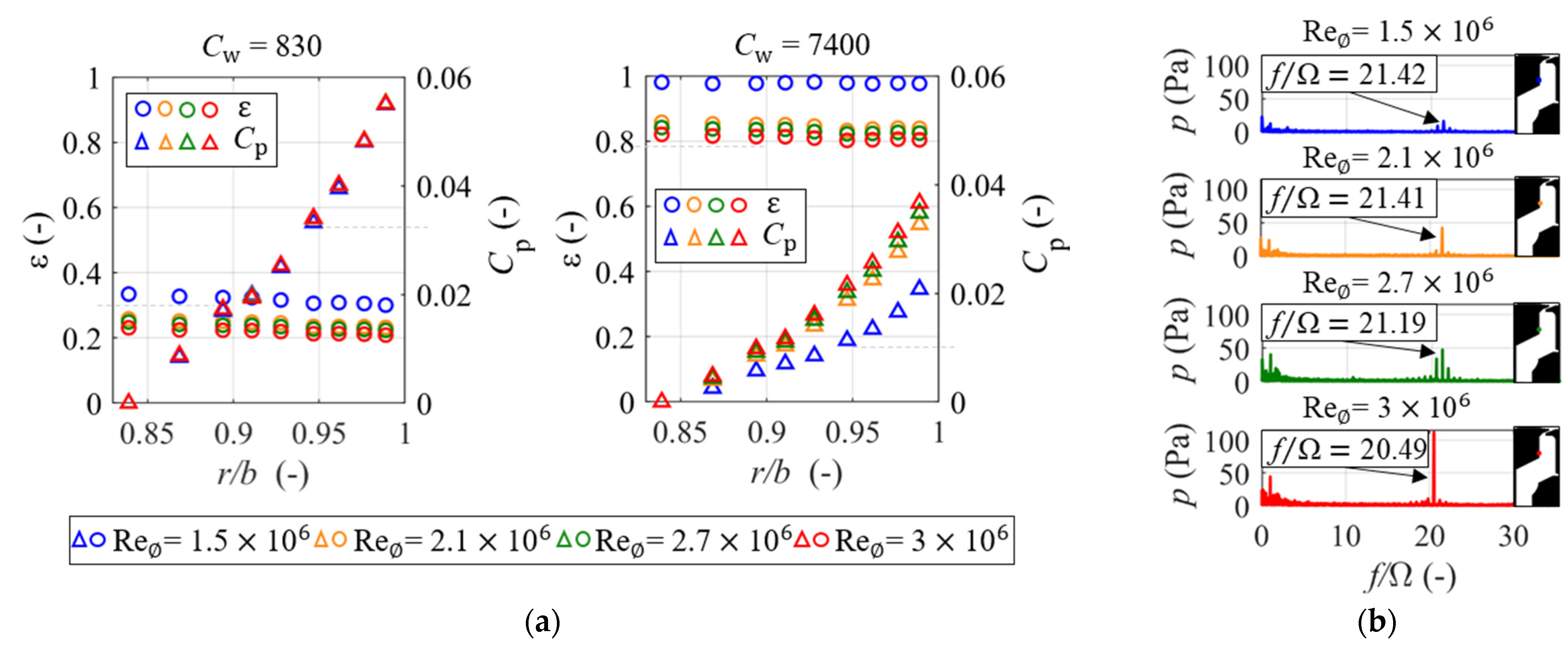
At low rates of purge flow (
Cw = 830),
Figure 5a left shows that disc pumping draws relatively large amounts of external flow through the rim seal, leading to low values of sealing effectiveness. This is due to the pressurisation of the cavity not being sufficient to overcome the disc pumping effect at any of the rotor disc speeds studied.
Figure 5a right shows how a higher non-dimensional purge flow rate (
Cw = 7400) reduces the gradient of the radial pressure distribution. A drastic increase in sealing effectiveness occurs as a direct consequence of the drop in pressure coefficient. A fully sealed cavity is achieved at
= 1.5 × 10
6. Larger sensitivity of both
Cp and sealing performance to the rotational Reynolds number is observed for the highest purge flow supply. A significant contrast in
between results at
= 1.5 × 10
6 and all the other rotor disc speeds is visible in
Figure 5a both at
Cw = 830 and
Cw = 7400, with the difference also being noticeable in the
Cp of the right plot.
The frequency spectra presented in
Figure 5b show an increase in the peak amplitude proportional to the rotor disc angular velocity, typical for all the purge supplies and seal clearances tested. The stronger pressure gradient in the cavity, as a consequence of the intensification of the disc pumping effect, translates into an isolated outstanding peak of higher amplitude and frequency. This confirms that the phenomena is rotationally driven and potentially caused by the increased shear of the cavity vortices at
r/b = 0.93. However, when non-dimensionalised by rotor disc speed, a slight shift towards lower non-dimensional peak frequencies is observed. Please note that the spike at
f/Ω = 1 corresponds to the frequency of the rotating disc and it could be caused by a slight eccentricity of the rotor disc.
4.2. Effect of Purge Flow
Larger supplies of purge flow to the seal increase the cavity pressure and counteract the disc pumping, ultimately preventing ingestion. A rise in sealing effectiveness with purge flow rate at all the radial positions considered is observed in
Figure 6. A decrease in sealing effectiveness for the wider gap is evident when comparing data for constant
Um/(Ω
b) = 0.02 (
Cw = 850) looking at the blue markers across the two plots.
The radial profile of sealing effectiveness can be explained by the cavity flow structure. When ingestion occurs, the external flow that reaches the cavity mixes with the outward purge flow in the outer part of the volume. The combined flow then merges with the stator boundary layer and migrates radially downwards. A constant radial distribution of sealing effectiveness is observed in
Figure 6 at the inner part of the cavity (
r/
b < 0.93) indicating that the flow is fully mixed all along the stator boundary layer. On the contrary, at higher radii (
r/
b > 0.93) radial variations in the sealing effectiveness distribution indicate partial mixing of ingested annulus and cavity flows. It is also worth noting that the geometrical discontinuity of the stator wall joining the flat vertical and angled faces at
r/
b = 0.93 aids this effect and the change consistently takes place at this radial coordinate.
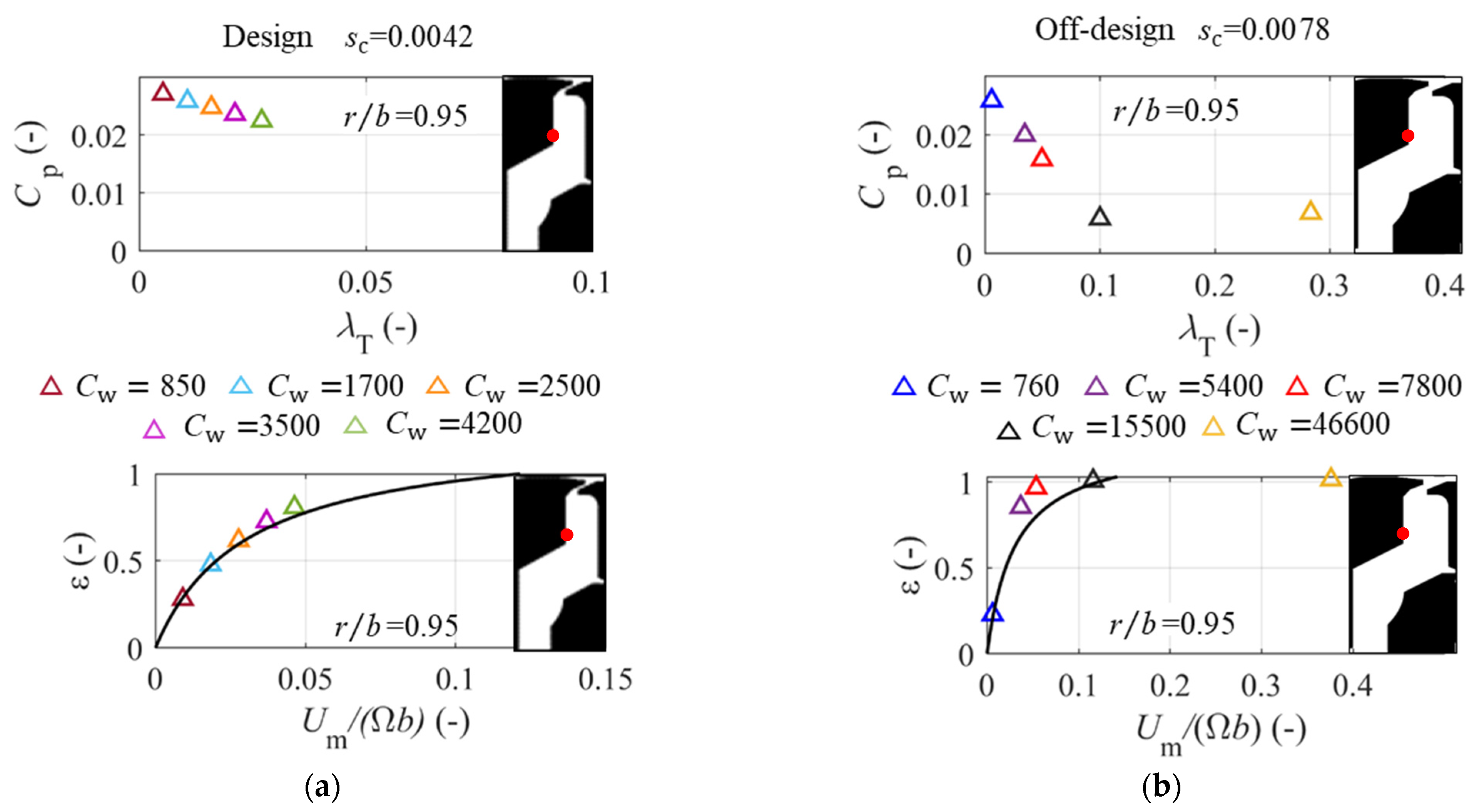
Higher values of turbulent flow parameter, λ
T, reduce the swirl velocity thus generating lower pressure gradients across the cavity. Interestingly,
Figure 7b reveals that for λ
T > 0.1, the pressure coefficient tends to an asymptotic value. When the purge flow satisfies disc pumping for λ
T = 0.219 as shown by Childs [
12], the recirculation and formation of a rotating core in the cavity is suppressed. Estimates of free disc pumping with allowance for the effect of a non-zero inner radius of the disc are consistent with a change of flow behaviour at λ
T~0.1 as reflected in
Figure 7b.
4.3. Effect of Seal Clearance
Figure 7a,b show pressure coefficient and sealing effectiveness results for the two seal clearances at
r/b = 0.95. Sealing effectiveness data show reasonable agreement with the disc pumping correlation derived by Chew [
4] and shown in Equation (1), although the data for the larger seal clearance generally sit above the analytical prediction. This suggests a superior sealing capability of the open rim geometry as shown in
Figure 7b (please note the wider range of purge flows tested at off-design). Here, the empirical constant in the model,
k, is set to 1, as it was shown to best fit the experimental data for a chute seal by Bru Revert et al. [
9]. Therefore, the underprediction for the larger clearance suggests that a slightly lower value of
k is needed to represent this seal. The increase in gap size was achieved by axially displacing the rotor disc rearwards, and consequently the overlap in the chute seal was lost. This change in configuration intrinsically modified the rim seal geometry into an axial seal of 0.5 mm clearance. This is consistent with the comparison against available experimental data of an axial rim seal reported by Bru Revert et al. [
1] that fitted Chew’s orifice model with
k = 0.8.
4.4. Effect of Mainstream Flow
The effect of the annulus flow on the sealing performance of the chute seal has been investigated for a wide range of conditions and is summarised in
Figure 8. Data correspond to
= 1.5 × 10
6 (left) and
= 2.7 × 10
6 (right) for the test cases without and with axial annulus flow. The results presented were measured at the rim,
r/
b = 0.99, for the larger seal clearance,
sc = 0.0078. The imposed annulus flow was purely axial with a Mach number of 0.34 (axial Reynolds number of 2.6 × 10
5 referenced to the nominal NGV axial chord).
Figure 8 reveals that the addition of axial annulus flow aids the sealing performance of the chute seal under certain circumstances. There is a value of
Cw at which the sealing effectiveness under axial annulus flow equals that of the configuration without it. As purge flow rate increases from this point, the presence of mainstream flow seems to exert a beneficial effect on the sealing capability of the chute seal. The pressure coefficient shows little sensitivity to the presence of annulus flow.
The study conducted by Phadke and Owen [
5] reported an improvement of the sealing capability when the external environment presented a weak quasi-axisymmetric flow. Past a certain threshold (
≥ 2 × 10
5 for
sc = 0.01), their data revealed a detrimental effect of the external flow. Note that different definitions of Reynolds number across studies may apply. These results are in broad agreement with the measurements obtained in the ORF. Bear in mind that Phadke and Owen’s experimental set up struggled to achieve an axisymmetric mainstream flow and the pressure non-uniformities in the gas path amplified with higher flow rates.
The sealing effectiveness is sensitive to the annulus flow conditions at high purge flow rates when
. In this particular case, it appears that a purge supply able to satisfy
Cp = 0.04 is sufficient to overcome the disc pumping effect and could benefit the sealing performance. The value of
Cw at which this occurs depends on the rotor disc speed. A stronger pressure gradient in the cavity is generated at higher rotational Reynolds number, thus demanding larger flow rates to pressurise the cavity and outbalance the disc pumping effect. In the specific cases depicted in
Figure 8, values of
Cw~3000 and
Cw~5000 are required to satisfy the condition for the low and high rotational Reynolds number respectively. This improvement in sealing capability in the presence of external flow could be a consequence of the flow recirculation in the rim seal region due to the interaction between purge and annulus flows that intensifies at higher rates of sealing air supply. The flow visualisation technique employed by Phadke and Owen revealed a separation bubble at the rim that reduced the effective separation between the stator and rotor discs therefore restricting ingestion. The CFD analysis of Savov and Atkins [
13] showed that the gap recirculation zone reduced in size and was blown out of the rim seal passage into the main gas path at high flow rates. The turbulent mixing of the purge and annulus flow would then occur in the annulus and ingestion would be inhibited. Experimental evidence supporting this hypothesis is provided here.
The effect of the seal clearance can be assessed by examining
Figure 9a. The gap size appears to more largely impact the amplitude of the frequency spike than the non-dimensional frequency of the peak. This suggests that the intensity of the unsteady pressure fluctuations decreases in the off-design axial-like seal geometry. The methodology detailed by Beard et al. [
10] to obtain the lobe count and rotational speed of the unsteady flow structures was applied to this experimental campaign, obtaining 27 lobes rotating at 76% of rotor disc speed at the highest rotational speed. The results from this study are in good agreement with those previously reported by Beard et al. [
10] and show that at higher rotor disc speeds both the lobe count and the angular speed of the structures slightly reduced.
The frequency spectra of the unsteady pressure signals across the test matrix reveal that the introduction of external axial flow does not have a strong impact on the non-dimensional frequency of the distinct peak (top plots in
Figure 9a,b). However, an increase in the unsteady activity under an axial axisymmetric mainstream flow is registered around
f/Ω~8 and is attributed to the complex interaction and shear between the annulus and purge flows in the rim seal region. Indeed, a lower rotational Reynolds number reduces the intensity of the disc pumping effect as discussed in
Figure 5b which in turn translates into a distinct peak of decreased amplitude. Under the influence of the mainstream annulus flow, the bottom plot in
Figure 9b reveals an intensification of the broadband unsteadiness and the characteristic spike of the disc pumping effect no longer stands out. Interestingly, the increased unsteadiness originated by the interaction of the annulus and purge flows appears at a constant frequency. Nonetheless, the frequency non-dimensionalisation with rotor disc speed gives a false illusion of a shift towards higher frequencies. A more detailed analysis of this dataset will be the subject of a future publication.
5. Conclusions
The Oxford Rotor Facility has been modified to investigate rim sealing flows with more extensive instrumentation installed in the stator-rotor cavity to measure pressure and gas concentration.
Steady pressure measurements have revealed the presence of different vortex strengths in the outer and inner sections of the cavity, implying that the change in geometry in the stator wall is inducing two different, coexisting vortices. The frequency spectra of the unsteady pressure signals present a maximum amplitude peak at r/b = 0.95, which is close to the change in stator wall geometry. Extended radial unsteady pressure transducers investigated the possible origin of the excitation further inboard in the cavity down to the overlapping seal and concluded this was not the source of the unsteadiness. The cavity flow unsteadiness is therefore associated with flow effects of the interface of the two vortices and is linked to rotating flow structures in the rim seal region identified in previous experimental and computational studies.
The effect of the rotor disc speed has been found to be dependent on the purge flow rate: at low supplies of sealing flow a large pressure gradient across the cavity appears to be insensitive to disc speed, whilst rotational effects have been identified at large rates of purge flow. The frequency spectra reveal an increase in the amplitude of the distinct frequency peak with angular speed of the rotor disc, indicating this is a rotationally dominated phenomenon.
The sealing performance is better for the larger seal clearance tested than for that of the smaller gap at the same value of Um/(Ωb). That is, increasing the seal clearance requires a lower increment in purge flow than simple, proportional scaling would suggest. The frequency spectra from the unsteady pressure traces reveal that an increase in the gap size has a larger impact on the amplitude of the pressure fluctuations of the unsteady flow structures than on the speed at which they travel.
The introduction of mainstream annulus flow exerts a beneficial effect in the sealing capability of the chute seal at conditions where sealing effectiveness is greater than ~0.75. At the two conditions investigated this has been found to occur at Cp~0.04. The interaction between the purge and annulus flows has been registered as an excitation of a band of frequencies at f/Ω~8. The broadband unsteadiness is further increased when the effect of the disc pumping effect reduces at lower rotor disc speeds until the distinct peak no longer stands out in the frequency spectra.
The study by Bru Revert et al. [
1] showed that rotationally induced ingestion may be the dominant mechanism in cases of low flow coefficient in which pressure asymmetries derived from NGVs exist in the gas path, such as high pressure turbines. This publication contributes towards an improvement of the understanding of the disc pumping effect and the flow behavior in the rim seal region through a more comprehensive analysis allowed by three different sets of measurement techniques complementing each other.
Author Contributions
Conceptualisation, methodology, formal analysis, investigation, data curation, writing—original draft preparation, A.B.R.; supervision and project administration, P.F.B.; writing—review and editing, P.F.B. and J.W.C. All authors have read and agreed to the published version of the manuscript.
Funding
This research was funded Rolls-Royce plc and Innovate UK through the TSB 113076 grant.
Data Availability Statement
Not applicable.
Acknowledgments
The authors wish to acknowledge the guidance provided by Sebastiaan Bottenheim and Peter Smout as well as the technical support of Gregory King, Sunny Chana and James Carter.
Conflicts of Interest
The authors declare no conflict of interest.
Nomenclature
| disc radius, m | Greeks |
| tracer gas concentration, % | | sealing effectiveness |
| NGV axial chord, m | | turbulent flow parameter |
| non-dimensional purge flow rate | | dynamic viscosity, Pa s |
| cavity pressure coefficient, | | fluid density, kg m−3 |
| rim seal gap size, m | | angular rotational speed, rad s−1 |
| empirical constant | Subscripts |
| mass flow, kg s−1 | 0 | total conditions |
| pressure, Pa | ax | axial component value |
| axial flow Reynolds number | min | minimum value |
| rotational Reynolds number | purge | purge flow value |
| seal clearance | Acronyms |
| temperature, K | CFD | computational fluid dynamics |
| axial velocity, m s−1 | NGV | nozzle guide vane |
| mean flow velocity through seal, , m s−1 | ORF | Oxford Rotor Facility |
References
- Bru Revert, A.; Beard, P.F.; Chew, J.W.; Bottenheim, S. Performance of a Turbine Rim Seal Subject to Rotationally-Driven and Pressure-Driven Ingestion. J. Eng. Gas Turbines Power 2021, 143, 081025. [Google Scholar] [CrossRef]
- Daily, J.W.; Nece, R.E. Dimension Effects on Induced Flow and Frictional Resistance of Enclosed Rotating Discs. J. Basic Eng. 1960, 82, 217–230. [Google Scholar] [CrossRef]
- Bayley, F.J.; Owen, J.M. The Fluid Dynamics of a Shrouded Disk System with a Radial Outflow. J. Eng. Power 1970, 92, 335–341. [Google Scholar] [CrossRef]
- Chew, J.W. A Theoretical Study of Ingress for Shrouded Rotating Disk Systems with Radial Outflow. J. Turbomach. 1991, 113, 91–97. [Google Scholar] [CrossRef]
- Phadke, U.P.; Owen, J.M. An Investigation of Ingress for an “Air-Cooled” Shrouded Rotating Disk System with Radial-Clearance Seals. J. Eng. Power 1983, 105, 178–182. [Google Scholar] [CrossRef]
- Cao, C.; Chew, J.W.; Millington, P.R.; Hogg, S.I. Interaction of Rim Seal and Annulus Flows in an Axial Flow Turbine. J. Eng. Gas Turbines Power 2004, 126, 786–793. [Google Scholar] [CrossRef] [Green Version]
- Scobie, J.A.; Sangan, C.M.; Owen, M.; Lock, G.D. Review of Ingress in Gas Turbines. J. Eng. Gas Turbines Power 2016, 138, 120801. [Google Scholar] [CrossRef]
- Chew, J.W.; Gao, F.; Palermo, D.M. Flow mechanisms in axial turbine rim sealing. Proc. Inst. Mech. Eng. Part C J. Mechan. Eng. Sci. 2018, 233, 7637–7657. [Google Scholar] [CrossRef] [Green Version]
- Bru Revert, A.; Beard, P.F.; Chew, J.W.; Bottenheim, S. Sealing Performance of a Turbine Rim Chute Seal Under Rotationally-Induced Ingestion. J. Phys. Conf. Ser. 2020, 1909, 012035. [Google Scholar] [CrossRef]
- Beard, P.F.; Gao, F.; Chana, K.S.; Chew, J. Unsteady Flow Phenomena in Turbine Rim Seals. J. Eng. Gas Turbines Power 2017, 139, 032501. [Google Scholar] [CrossRef] [Green Version]
- Gao, F.; Chew, J.W.; Marxen, O. Inertial waves in turbine rim seal flows. Phys. Rev. Fluids 2020, 5, 024802. [Google Scholar] [CrossRef] [Green Version]
- Childs, P.R.N. Rotating Flow; Elsevier: Amsterdam, The Netherlands, 2010. [Google Scholar]
- Savov, S.S.; Atkins, N.A.; Uchida, S. A comparison of Single and Double Lip Rim Seal Geometries. J. Eng. Gas Turbines Power 2017, 139, 112601. [Google Scholar] [CrossRef]
| Publisher’s Note: MDPI stays neutral with regard to jurisdictional claims in published maps and institutional affiliations. |
© 2021 by the authors. Licensee MDPI, Basel, Switzerland. This article is an open access article distributed under the terms and conditions of the Creative Commons Attribution (CC BY-NC-ND) license (https://creativecommons.org/licenses/by-nc-nd/4.0/).


