1. Introduction
The outflow velocity level of thermal turbomachinery is typically rather high. This high-velocity level can cause substantial exergy losses in subsequently placed heat exchangers, because traditionally, heat exchangers are not designed for high-speed flows. For instance, the layout of a steam power plant is largely affected by exhaust losses due to the combination of a low-pressure steam turbine with a high Mach number exhaust flow and a condenser, as discussed in detail by aus der Wiesche and Joos [
1]. In the case of gas turbines, the thermodynamic benefits of cycles with intercoolers and regenerators are well-known, but this approach is characterized by significant pressure losses in the heat exchangers which makes their use in large power plants challenging. In the case of aero engines, an interesting way to improve the specific fuel consumption is to add a regenerator, but this is normally not performed with gas turbines used for propulsion because of the added weight. One exception was the early Allison T78 turboprop engine, shown in
Figure 1, which was an attempt to build an engine with much lower fuel consumption at partial power [
2,
3,
4]. Today, the reduction in gas turbine-specific fuel consumption using heat exchangers is becoming a topic with increasing importance. In organic Rankine cycle (ORC) power systems, it is usual to add a heat exchanger directly after the ORC turbine to preheat the working fluid, as illustrated by an example shown in
Figure 2. Currently, regarding the regenerator, that approach is extremely disadvantageous because the hot exhaust vapor flow is typically transonic or even supersonic due to the low speed of sound of organic vapors. Hence, significant exergy losses result which reduce the total cycle efficiency [
5].
In all the cases discussed above, the use of a transonic or supersonic flow heat exchanger with low-pressure losses and high convective heat transfer coefficients would be very attractive. Any heat exchanger design based on blunt bodies, such as tubes placed in the high-speed crossflow, would lead to substantial shock losses. An interesting technical solution to that problem might be provided by the use of pillow-plate devices. Pillow-plate heat exchangers (PPHE) are a novel heat exchanger type based on a wavy pillow-like plate geometry, as shown schematically in
Figure 3.
Typically, PPHE are composed of parallel plates arranged as a stack [
7]). One flow path of a PPHE can be designed as a smooth, wavy wall-bounded channel. The smooth changes in the channel profile help to reduce pressure losses. Furthermore, it is known from low-speed flow applications that the convective heat transfer coefficients are comparatively high due to the mixing effect at the welding spots working as heat transfer, increasing dimples in the hot stream path [
8].
In the past, low-speed flows in pillow-plate heat exchangers were investigated in detail (see, for instance, [
7,
8,
9]). The first discussion of high-speed flow phenomena in pillow-plate channels was proposed recently by Passmann et al., who presented computational fluid dynamics (CFD) results for an adiabatic pillow-plate channel flow [
10]. These results qualitatively supported the analytical prediction that this type of flow could be under stood as a kind of Fanno flow. The conclusion that high-speed flows in pillow-plate channels would be described by a quasi-one-dimensional compressible flow model with friction and heat transfer (Fanno–Rayleigh flow) has significant implications for the system behavior, i.e., the operation performance of a combined turbine-heat exchanger device.
This will be pointed out in the following section in more detail. Furthermore, the outcome of an experimental study is used to confirm the validity of the proposed Fanno–Rayleigh flow model. This experimental investigation enables detailed insight into high-speed flow phenomena occurring in pillow-plate channels, and the data validated the CFD analysis method employed by Passmann et al. [
10].
2. One-Dimensional Fanno–Rayleigh Flow Model
In turbomachinery design processes, a mean line analysis is typically performed at the beginning and provides relevant information for more detailed analyses. In the present case, the considered turbomachinery and the hot gas flow through a pillow-plate heat exchanger establish the technical system for which an essentially one-dimensional compressible flow analysis has to be conducted. Such a configuration is shown schematically in
Figure 4, where the turbine is simplified through an equivalent nozzle which creates the inflow conditions (index 1) for the pillow-plate channel. The exit station of the pillow-plate channel is denoted by index 2, and its stream-wise coordinate is denoted by
x. The lateral coordinates would be
y and
z. Although an actual turbine is not a passive nozzle, for the present purpose this simplification is sufficient because the overall characteristic of a high-speed turbine performance is well-approximated by a choking mass flow behavior, similar to a nozzle, as discussed by Dixon and Hall [
11] or Horlock [
12]. The flow with friction (characterized by the friction factor
f) in the pillow-plate channel is subjected to external heat addition or heat loss (denoted by the symbol
q).
Due to the general balance equations, all possible flow states occurring in the pillow-plate channel are on a Fanno–Rayleigh flow line in the
T,
s diagram for a given mass flow rate. The lines for ideal Fanno flow and ideal Rayleigh flow are plotted schematically in
Figure 5. Without friction but with heat transfer, the possible flow states would be described by the Rayleigh flow line in
Figure 5. Cooling processes would move the flow states away from the point
with maximum entropy
s. In the case of subsonic flow (entry Mach number
), lower exit Mach numbers would result due to cooling, whereas in the case of supersonic flow (entry Mach number
), the Mach number would increase due to cooling. For the supersonic branch of the Rayleigh line, a shock could occur in the cooling channel leading to a subsonic flow state, as sketched in
Figure 5 (see John and Keith [
13]). The condition for that shock is given at the common point of the Fanno and the Rayleigh flow lines (at the given mass flow rate).
Considering the fundamental balance equations for an arbitrary control volume along the mean-stream coordinate
x, the following Fanno–Rayleigh flow equation, including channel cross-section area changes, friction, and heat transfer, can be derived for an ideal gas with isentropic exponent
γ:
In Equation (1),
A denotes the effective cross-section area of the pillow-plate channel with
D as the hydraulic diameter. The friction factor
f is defined using the wall shear stress
by
. In the case of fully turbulent pillow-plate channel flow, a relationship between the friction factor
f and the heat transfer coefficient
h exists due to Reynold’s analogy [
13]. The heat transfer term in Equation (1) can be evaluated explicitly for a specific thermal boundary condition. For instance, in the case of a constant wall heat rate, the heat transfer term can be expressed as a function of the total temperature
which is a function of the Mach number
due to the isentropic condition.
For a pillow-plate channel, see
Figure 3, the area term
in Equation (1) is periodic and rather small due to the smooth profiles with its moderate relative area changes. Hence, the overall behavior of the system might be expressed qualitatively by the Fanno–Rayleigh flow without area changes. Skipping the area term in Equation (1) and neglecting heat transfer, it is a straightforward task to obtain the choking limit of the system. Integrating the resulting equation from
(the entry with entry Mach number
) and as suming the choking limit
at the end of the pillow-plate channel at
, a relationship between the entry Mach number and the length
of the pillow late channel results:
Equation (2) relates the pillow-plate channel length L and the entry Mach number for achieving choking conditions at the exit of the channel. For instance, in the case of , the limiting value results for M → ∞. This means that in the case of supersonic inflow, the maximum length of an adiabatic pillow-plate channel might be rather small in terms of (however, the friction factor for supersonic flow past smooth boundaries is of order , and hence the maximum length might be many times the hydraulic diameter ).
The choking condition at the end of a long pillow-plate channel governs the maximum mass flow rate through the system. Due to additional cooling, the maximum mass flow rate can be increased, but in the case of heating, the heat supply leads to a stronger choking effect which reduces the maximum theoretical length. Then, a longer pillow-plate channel would lead to a reduction in the mass flow rate. These mechanisms have important consequences for the turbine exit state (exhaust pressure) and the turbine mass flow rate. The addition of the pillow-plate heat exchanger tends to reduce the mass flow rate through the entire system, and the design of the turbine would be directly affected by the choking effect of the Fanno–Rayleigh flow due to its impact on the resulting pressure distribution.
Although the above discussion (i.e.,
Figure 5 and Equations (1) and (2)) considers explicitly a perfect gas, the main physical mechanism may be assumed for a non-ideal gas or an organic vapor at least in the dilute gas regime, too. Then, the isentropic exponent
would be replaced with a generalized exponent (see, for instance, Kouremenos and Antonopoulos [
14]).
3. Linearized Gas Dynamics and Pillow-Plate Channel Flows
In addition to the above one-dimensional model for compressible flow with friction and heat transfer, valuable information about the bulk flow velocity and pressure distribution within the pillow-plate channel can be obtained through linearized gas dynamics. The linearization of the gas dynamical governing equations is a powerful method in the case of smooth profiles and inviscid flow because analytical results and certain relationships between the flow variables can be derived [
13]. In linearized gas dynamics, it is usual to express the velocity field as a sum of a main, uniform velocity,
U, and a perturbation velocity field which can be calculated from a velocity potential
φ. Wavy-wall effects on the resulting flow are included in the perturbation velocity potential
φ. This perturbation velocity potential
φ can be calculated by solving the (subsonic) perturbation equation.
In Equation (3), is the local Mach number of the undisturbed main flow (with velocity U) in the channel center at (with channel height H) which is a function of the streamwise coordinate x.
3.1. Coherent Pressure Oscillations
The perturbation potential depends on the boundary conditions which are prescribed by the wall surface elevation function
. In the case of pillow plates, the periodic wall-surface elevation function
can be expressed utilizing double Fourier series with modes
. Due to the linear character of the perturbation Equation (3), each elevation mode can be considered separately and the final solution of
φ can be calculated as the sum of modes.
The above solution (4) leads to the result that pressure oscillations that are coherent with the pillow-plate elevation oscillations occur in the case of subsonic flow through the channel. This can be seen by inserting solution (4) into the static pressure coefficient definition.
The sinusoidal wall pressure oscillations due to the wavy wall are exponentially damped with increasing wall distance z in subsonic flow. In the case of a finite channel height H, these oscillations are still observable in the centerline of the channel ().
3.2. Similarity Rules for Subsonic Flow and Incompressible Flow Results
In the scientific literature, many results are available for incompressible flow through pillow-plate channels [
7,
8]. The linearized gas dynamics directly leads to the Prandtl–Glauert and Goethert similarity rules which connects the (subsonic) compressible flow with its incompressible reference [
13]. The following general conclusions can be drawn in the framework of this linearized theory:
In the case of a fixed pillow-plate geometry, the static pressure coefficient (5) can be related to its incompressible flow result Cp,i by the Prandtl–Glauert factor, i.e., . This means that the amplitude of the coherent oscillations increases with increasing Mach number.
The perturbation Equation (3) enables the interpretation that compressible flow in the coordinate system (
x,
y,
z) is equivalent to an incompressible flow (subscript
i) if the transformation
,
and
are assumed. For example, a pillow-plate design characterized by some certain values for its geometric parameters
hmin,
hp, and
sL (see
Figure 3) which would lead to an optimal heat transfer behavior in the incompressible flow regime might be stretched according to the coordinate transformation rules to create a new optimal pillow-plate channel design for compressible flow at a subsonic Mach number
M.
4. Experimental Setup and Procedure
The above theoretical considerations and predictions were checked through an experimental study using an adiabatic pillow-plate channel (the addition or loss of heat in the test channel would require substantial additional efforts which were out of the scope of the present validation study).
The experimental investigations were performed utilizing a blow-down wind tunnel which is schematically shown in
Figure 6 and explained in more detail by Passmann et al. [
15]. The working fluid was compressed air (maximum pressure 8 bar). The filling of the air storage tanks was enabled by the magnetic valve MV1. The temperature and pressure of the storage tank system were recorded continuously. The complete test facility was controlled using a PC and LabView software, from the manufacturer National Instruments, based in Austin, Texas. The blow-down test run was controlled by a coaxial valve CV1, see
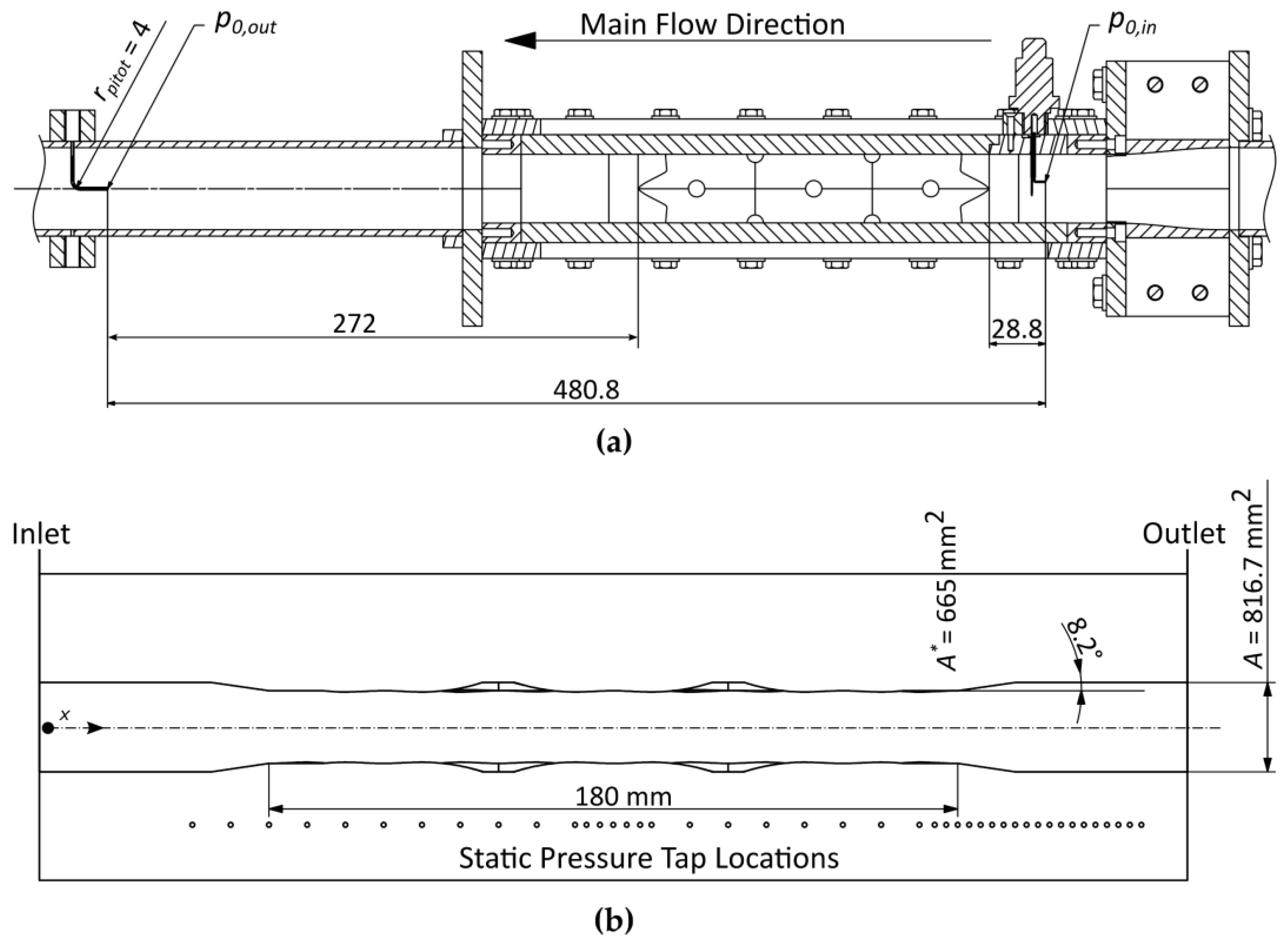
Figure 6. The pillow-plate channel was placed in the test section of the wind tunnel, as illustrated in
Figure 7a.
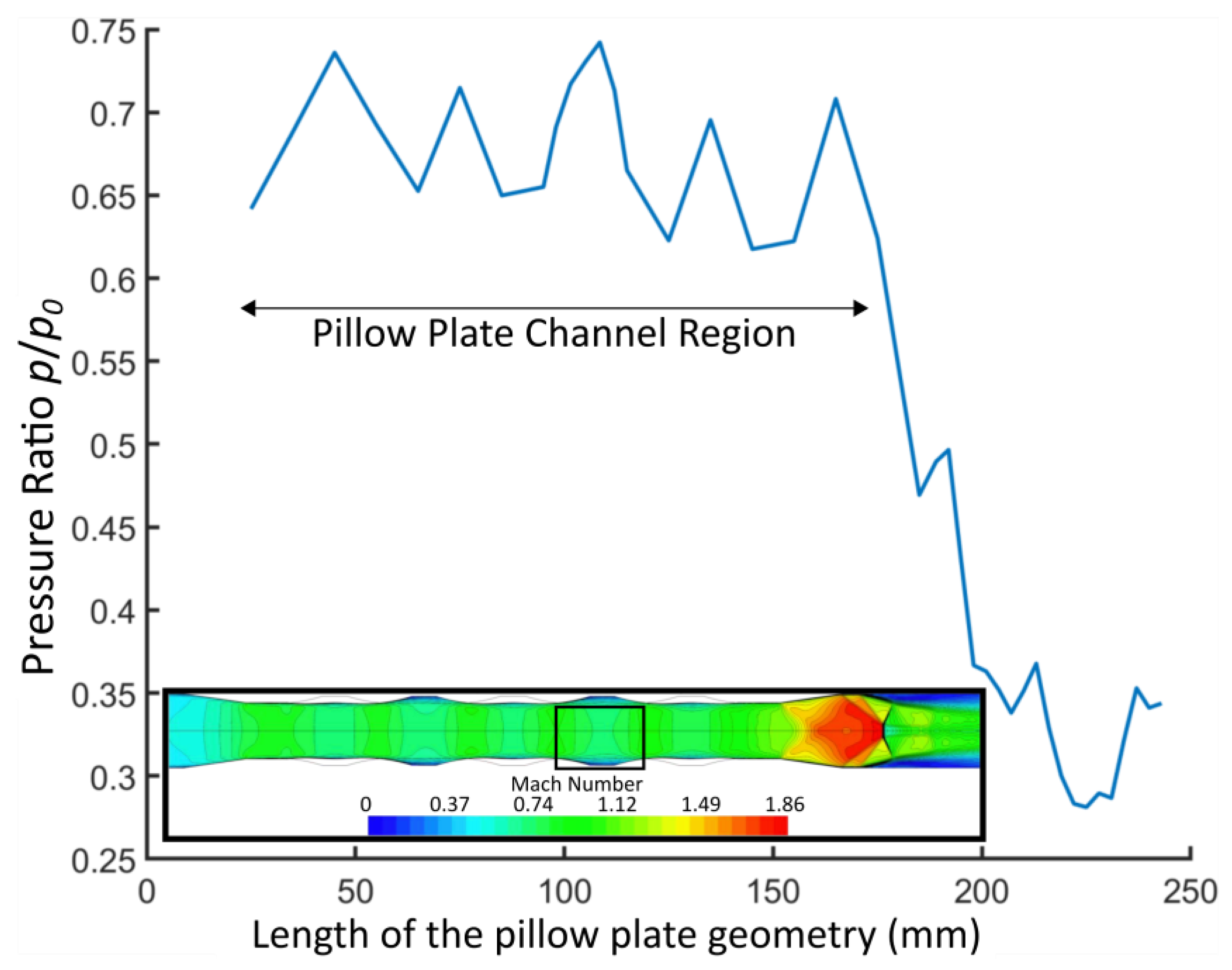
The test section inlet and outlet flow conditions were obtained by static and total pressure measurements. In prior tests, it was found that the inlet Pitot probe did not significantly disturb the inflow. The static pressure distribution along the center of the pillow-plate channel was measured employing 40 taps placed centrally at the pillow-plate channel end wall, see
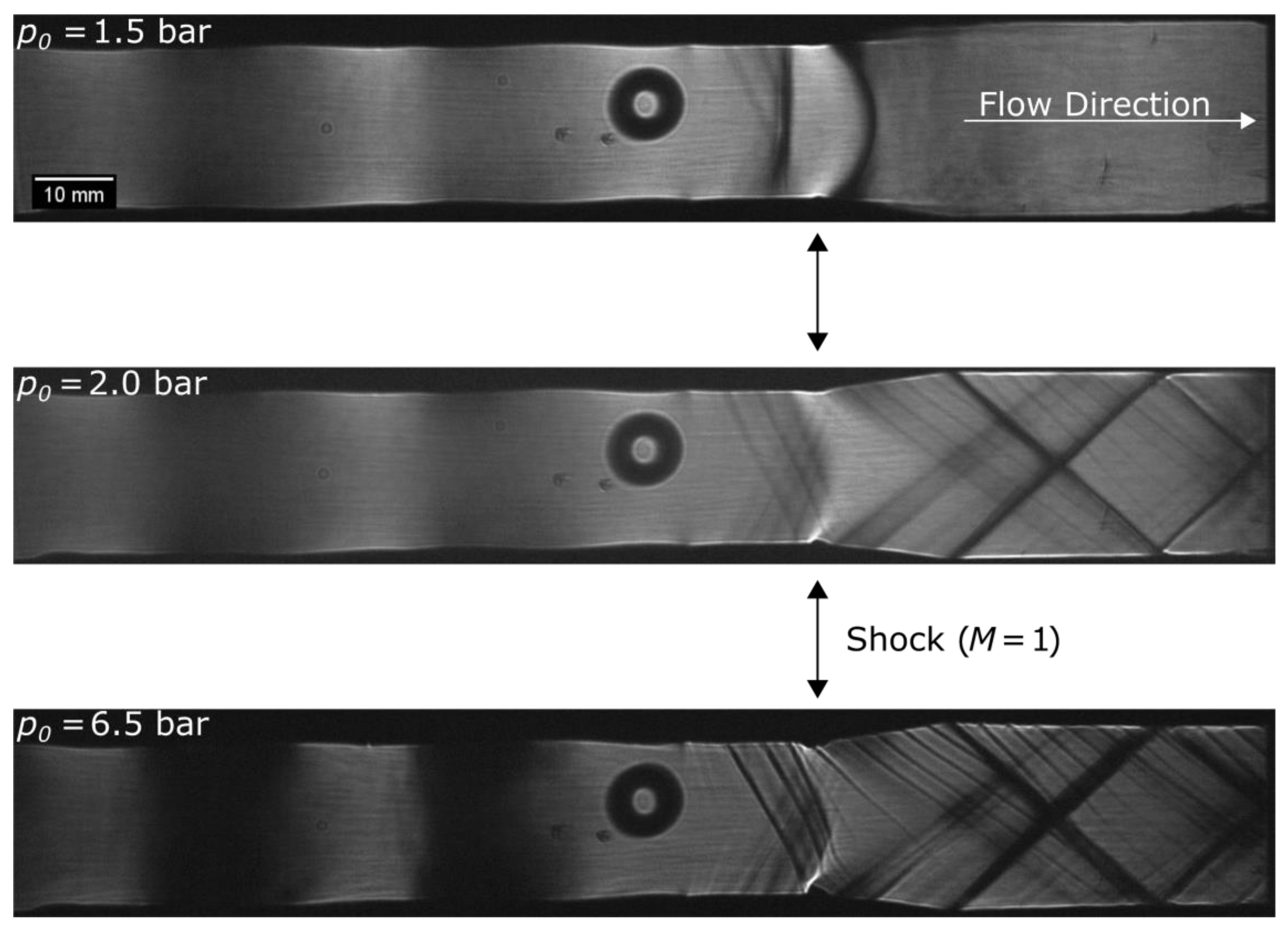
Figure 7b. In addition to static and total pressure measurements, the transparent sidewalls of the pillow-plate channel enabled an optical visualization using both conventional and focusing schlieren optics. Furthermore, surface oil flow visualization studies were performed to obtain a qualitative picture of the flow behavior.
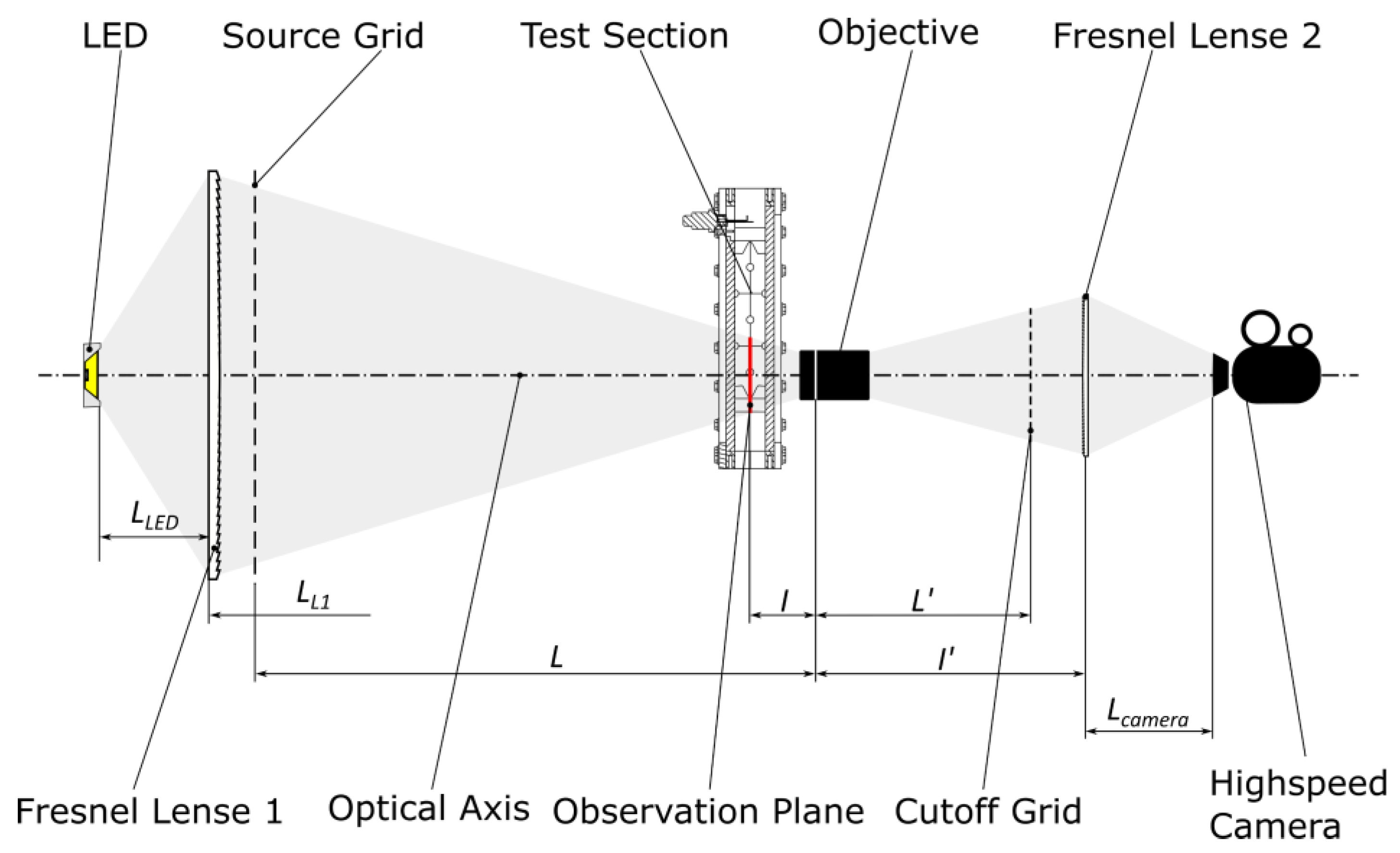
Whereas conventional schlieren optics are treated well in the literature, focusing schlieren optical systems are employed less frequently. The principal setup of the employed focusing schlieren optics is shown in
Figure 8, and details can be found elsewhere (see Weinstein [
16] and Passmann et al. [
17]). In combination with a high-speed camera, the focusing schlieren optics enabled a detailed visualization of transient phenomena at certain observation planes in the test section.
6. Conclusions
In this work, the overall system behavior and high-speed flow details in pillow-plate channels were investigated experimentally. A pillow-plate channel was placed in the test section of a blow-down wind tunnel working with dry air, and the resulting gas dynamics were investigated utilizing conventional and focusing schlieren optics. Further, static and total pressure measurements were performed. The results of this qualitative study were in good agreement with theoretical predictions for compressible flow past pillow-plate channels.
Regarding potential applications of pillow-plate heat exchangers in combination with high-speed turbomachinery, the following conclusions can be drawn:
The compressible flow through pillow-plate heat exchangers can be interpreted as a kind of Fanno–Rayleigh flow. This means that the choking behavior at the end of the channel has to be considered, which affects the exit conditions of the turbomachine. The pressure drop due to friction is comparably low in the pillow-plate channel, but high convective heat transfer coefficients can be expected due to the substantial mixing and vortex structures. These flow phenomena are rather similar to incompressible flow.
In summary, the observed effects suggest that pillow-plate heat exchangers are rather promising candidates for high-speed flow applications.


