Article

Acoustoelastic Modes in Rotor-Cavity Systems: An Overview on Frequency Shift Effects Supported with Measurements

Chair of Turbomachinery, University of Duisburg-Essen, 47057 Duisburg, Germany
*
Author to whom correspondence should be addressed.
Int. J. Turbomach. Propuls. Power 2022, 7(2), 15; https://0-doi-org.brum.beds.ac.uk/10.3390/ijtpp7020015
Submission received: 26 January 2022 / Revised: 31 March 2022 / Accepted: 4 May 2022 / Published: 6 May 2022
(This article belongs to the Special Issue Advances in Critical Aspects of Turbomachinery Components and Systems)

Abstract

:
With an increase in fluid densities in centrifugal compressors, fluid-structure interaction and coupled acoustoelastic modes receive growing attention to avoid machine failure. Besides the vibrational behavior of the impeller, acoustic modes building up in the side cavities need to be understood to ensure safe and reliable operation. In a coupled system, these structure and acoustic dominant modes influence each other. Therefore, a comprehensive overview of frequency shift effects in rotor-cavity systems is established based on findings in the literature. Additionally, experimental results on coupled mode pairs in a rotor-cavity test rig with a rotating disk under varying operating conditions are presented. Measurement results for structure dominant modes agree well with theoretical predictions. The development of a forward and a backward traveling wave is demonstrated for each mode in case of disk rotation. Conducted experiments reveal the occurrence of weakly and strongly coupled mode pairs as frequency shifts are observed that cannot solely be explained by “uncoupled mode effects”, such as the added mass, speed of sound, and stiffening effect, but indicate an additional coupling effect. However, the hypothesis of a bigger frequency shift for stronger coupled modes cannot be corroborated consistently. Only for the strongly coupled four nodal diameter mode pair in the “wide cavity” setup, a coupling effect is clearly visible in the form of mode veering.

1. Introduction

Centrifugal compressors are applied for a wide range of industrial applications, including gas compression for the chemical industry, natural gas extraction and liquefaction, enhanced oil recovery, as well as carbon capture and storage. Required discharge pressures increase continuously, and so do fluid densities inside the machines, increasing the forces acting on the impeller. Besides the vibrational behavior of the impeller, which has been studied extensively over the last decades, these fluid-structure interactions have to be understood. Nowadays, it is well known that natural frequencies of compressor impellers shift due to an increase in gas density of the surrounding fluid. Moreover, acoustic modes building up in the side cavities of radial compressors were found to be another potential source of high cycle fatigue. Recent studies suppose that acoustic and disk vibration modes influence each other, resulting in further frequency shifts in coupled rotor-cavity-systems. However, these effects are not fully understood yet. To ensure a safe and reliable design and avoid machine failure during operation, these coupled natural frequencies have to be predicted accurately, and the excitation and the damping mechanism need to be studied further.
Rotor-cavity systems, consisting of a rotating disk in a fluid-filled cavity, provide a simplified model of centrifugal compressors for fundamental research purposes. Therefore, a comprehensive overview on frequency shift effects in acoustoelastic rotor-cavity systems is established based on findings published in the literature. This provides a robust foundation for a theoretical understanding of the topic, which is then underpinned with measurement data. For this purpose, a rotor-cavity test rig was set up at the Chair of Turbomachinery at the University Duisburg-Essen (Germany) that demonstrates the occurrence of coupled acoustoelastic modes. It enables the researchers to systematically collect and evaluate experimental data on rotor-fluid interaction and the formation of coupled acoustic and structure dominant modes while varying different influencing parameters independently from each other. By doing so, a deeper understanding of coupling and frequency shift effects in rotor-cavity systems is gained.

2. Literature Overview

Some of the earliest works on disk vibration in turbomachinery were conducted by Lamb and Southwell (1921) [1] and Southwell (1922) [2], analyzing the vibrations of a spinning circular disk. A few years later, Campbell (1924) [3] published his fundamental study on the vibrational excitation of rotating turbomachinery, thereby establishing the so-called Campbell diagram. Until today, it remains a widely-used tool to avoid potential vibrational resonances that might result in machine failure. Subsequently, many studies were conducted analyzing the vibrational behavior of rotating disks and compressor impellers. E.g., Eversman and Dodson (1969) [4] published a technical note on the free vibration of spinning, centrally clamped circular disks, and presented an analytical solution of the Eigenvalue equation as a function of hub-to-disk ratio for different spin rigidity parameters and mode shapes. Ewins (1973) [5] published an analytical and experimental study on the vibration characteristics of tuned and detuned bladed disk assemblies, emphasizing the importance of considering the complete bladed disk assembly, instead of disk and blades separately. Irretier [6,7] studied the natural and forced vibrations of a wheel disk and established a numerical model to calculate the Eigen frequencies and mode shapes of the system and later carried out experiments and calculations on the vibrations of rotating radial impellers, which were in good agreement.
One of the first fundamental studies on aero-acoustic excitation sources in turbomachinery was published by Tyler and Sofrin (1962) [8]. They identified rotor-stator interaction as a significant noise generating mechanism and found that both the spinning rotor alone and rotor-stator interaction produce rotating pressure patterns. Since then, these spinning modes are referred to as Tyler-Sofrin modes. Ehrich (1969) [9] derived an analytic model of an annular acoustic cavity to conclude on natural frequencies of acoustic modes in the cavity. It is used to analyze experimental data of a turbomachine over a range of rotational speeds and explain resonance peaks at supersonic and subsonic wheel speeds. Amongst the more recent publications, Eisinger (2002) [10] and Eisinger and Sullivan (2002) [11] address acoustically induced fatigue of impellers of rotating machinery. Coupling of the structural and acoustic modes is discussed that might ultimately lead to structural failure of the impeller. This becomes especially important for impellers in high-density fluids, where disk vibration and acoustic modes cannot be treated separately anymore but need to be analyzed as a coupled system. Magara’s publications [12,13] are of particular interest along this chain of causation as they discuss structural frequencies of radial compressors in a high-density environment. Two analytical models are established to explain the subsequent frequency shift phenomena for a non-rotating and a rotating disk due to mode coupling. Experimental results agree well with numerical ones. Beirow et al. (2015) [14] studied the effect of mistuning on a high-pressure compressor blisk at rest with respect to structural vibration modes and damping ratios. The forced response is analyzed, and it is found that, taking aero-elastic coupling effects into account, damping of the structure generally increases while the response decreases. Based on other theoretic models, Heinrich et al. (2020) [15] proposed a generalized model for the approximation of coupled acousto-mechanical natural frequencies in high-pressure centrifugal compressors, which was later extended to take damping effects into account (Heinrich et al. (2021) [16]). In the latter, the model outcome is further compared to experimental data, yielding excellent agreement regarding the predicted natural frequencies and an acceptable agreement regarding damping ratios.
Examples of aero-acoustic excitation in industrial turbomachinery are, e.g., reported in Hellmich and Seume (2006) [17], where an acoustic resonance in a four-stage axial compressor is explained with a simplified model for helical acoustic modes, as well as König (2009) [18] and Petry et al. (2012) [19], who investigate acoustic Eigenmodes in the side cavities of an industrial centrifugal compressor. Their setup includes one complete compressor stage, from the inlet guide vanes to the return guide vanes. Another case of actual high cycle fatigue in an industrial compressor possibly caused by aero-elastic excitation is described in Eckert (1999) [20], accentuating that the problem of fluid-structure interaction in turbomachinery is of substantial concern in real applications.
The current paper is based on the preceding work of the research group at the Chair of Turbomachinery at UDE, aiming at gathering baseline experimental data on rotor-fluid interaction. Barabas et al. (2015) [21] introduced the test rig and measurement instrumentation in detail and presented first velocity profile measurements, indicating a turbulent flow with high Reynolds numbers inside the cavity. Barabas et al. (2017) [22] presented frequency shifts towards higher and lower frequencies for the two modes of a coupled mode pair for a change in cavity pressure. Moreover, interfering influences of crossing modes were identified. Barabas et al. (2018) [23] then focused on the damping of weakly coupled acoustic dominant modes, which was found to decrease with an increase in fluid pressure, and established a relationship of the damping ratio, the kinematic viscosity, and the natural frequency of the acoustic modes.
It is shown that structural-acoustic mode coupling in rotor-cavity systems is a complex field of research with many interacting effects to be taken into account. Several publications address some of these effects, but so far none has revealed them at large. This paper contributes to a deeper understanding of the coaction of all pertinent frequency shift effects in rotor-cavity systems and thus to the efforts to avoid resonances in centrifugal compressors that might ultimately lead to component failure in turbomachinery.

3. Theory on Frequency Shifts in Rotor-Cavity Systems

3.1. The Rotor-Cavity System

A rotor-cavity (or rotor-stator) system consists of an impeller rotating inside a stationary cavity. It can be used as a simplified model of turbomachine impellers in a casing. The rotating disk divides the fluid volume into two separate cavities, similar to the side cavities in, e.g., centrifugal compressors. The ratio of the cavity’s axial gap width s to the disk radius r d is a characteristic dimension describing the cavity, referred to as non-dimensional axial gap width G .
G = s r d
Between the disk vibration modes and the acoustic modes inside the fluid-filled cavities, fluid-structure interaction occurs if there is a resulting force from one to the other. These interactions present themselves in the form of the out-of-plane structural modes of the disk and fluctuating pressure patterns of the fluid that can only truly be neglected if the disk rotates in a vacuum. Structural and acoustic modes additionally influence each other if a certain mode pair is coupled. This results in a further frequency shift. In the case of coupling, the modes are referred to as structure and acoustic dominant modes.

3.2. Uncoupled Structure/Disk Vibrational Modes

The mode shape of disk vibration modes, also called structural modes, is characterized by the number of nodal diameters (diametral modes, or circumferential order) m and the number of nodal circles (or radial order) n. For a rotating disk, a resonance between a natural frequency f m , n of one of its disk modes and an excitation frequency f e , s t occurs when the latter coincides with the rotational frequency of the forward or backward traveling wave of the disk mode as follows [3]:
f e , s t = f m , n ± m × f
with f being the rotational frequency of the rotating disk.
Disk natural frequencies f m , n increase slightly with an increase in disk rotational speed Ω due to the stiffening effect of the centrifugal force field [7]. This effect can be approximated (as, e.g., in [2]) but is often sufficiently small to be neglected [7].
For a mistuned disk, i.e., a non-axisymmetric disk, there are two natural frequencies for one disk mode. However, this frequency splitting is often negligible for practical applications [7]. In general, the above-mentioned considerations also apply to rotating impellers. Nevertheless, mistuning due to geometrical non-uniformities becomes more likely for more complex impeller geometries [5]. Such detuning gives rise to more irregular and complex mode shapes and more resonances than those in equivalent tuned systems [5].

3.3. Uncoupled Acoustic/Cavity Modes

In a fluid-filled cavity, acoustic modes (or cavity modes) can form that establish as fluctuating pressure patterns. In rotating machinery, these acoustic waves are excited by the flow through the machine and can be enhanced by the impeller rotation [10]. Similar to structural modes, acoustic modes are characterized by their number of nodal diameters p, nodal circles q, and additionally, axial nodes r. The frequency of the (p,q) acoustic mode inside a cylinder can be calculated as follows [24]:
f p , q = ( π α ) p , q   c 2 π   r c
where ( π α ) p , q are the dimensionless solutions to the first derivative of the Bessel function for the (p,q) acoustic mode (see Figure 1). From Equation (3) we see that the natural frequency of the acoustic mode is linearly dependent on the fluid’s speed of sound c , and thus on the fluid properties. E.g., an increase in fluid pressure causes a shift in the natural frequency of the acoustic modes. This will be referred to as the speed-of-sound effect in the following. A change in cavity radius r c also results in a change of acoustic frequency; however, according to this model in Equation (3), a change in axial gap width does not.
In a rotor-stator system, disk rotation results in fluid rotation inside the cavity. These flow patterns influence the formation of acoustic modes and can be described depending on the circumferential Reynolds number R e , which is defined as follows:
R e = u   L ν = 2 π   Ω   r d 2 ν
where u is the circumferential velocity, L the characteristic length, and ν the kinematic viscosity of the fluid. The widely used rotor-stator cavity flow model by Daily and Nece (1960) [25] distinguishes between four flow regimes, the two turbulent ones having either merged or separated boundary layers. The latter is predominant for bigger cavity widths or higher Reynolds numbers and is characterized by a core flow, for which an almost constant circumferential velocity is assumed, i.e., the fluid is swirling as a bulk flow. The core rotation can be described by the ratio k 0 of the fluid velocity v f to the impeller circumferential velocity u and only depends on the geometry of the cavity if there is no superimposed through flow [26]. In the case of zero leakage flow, it is also independent of the radius and can be estimated as follows [26]:
k 0 = v f u = 1 1 + ( r c r d ) 2 ( r c r d + 5 t a x r d ) c f , c a s e c f , d 2
where r d and r c are the impeller and the cavity radius, t a x is the cylindrical portion of the impeller side room, and c f , d and c f , c a s e are the friction coefficients of the impeller and casing, respectively. Typically, the core rotation factor takes a value between 0.4 and 0.5, i.e., the fluid rotates at a rotational speed a little less than half of the disk speed.
Analogous to the structural modes, the acoustic modes subject to core rotation form a backward and a forward traveling wave in the cavities that can be calculated as follows:
f e , a c = f p , q ± k 0 × p × f Ω

3.4. Fluid-Structure Interaction

So far, the disk vibration and fluid-filled cavity have been treated separately. However, the influence of the surrounding fluid on the impeller has to be considered. Especially with an increase in fluid pressure and therefore density, significant forces are acting from the fluid on the impeller. Vice-versa, the out-of-plane structural modes also influence the acoustic ones. These effects are called fluid-structure-interaction and cannot be neglected. Of particular practical interest is the influence of an increased fluid density on the turbomachinery impeller, which is addressed by the added-mass-effect: An increase in mass of the surrounding fluid results in a decrease of the natural frequencies of the impeller [12,13,27], as the fluid mass is linearly dependent on the fluid density (and the cavity volume). Hence, while the impeller’s mass does not change, the total mass of the system changes as the fluid mass acting on the impeller varies. The change in natural frequency is anti-proportional to the change in total mass. However, these interactions are not of major concern unless coupling between a pair of acoustic and structural modes exists.

3.5. Coupling

The respective modes need to be excited first off for coupling between an acoustic and a structure mode to occur. While acoustic modes are excited by the fluid flow through the casing passing obstacles, such as vanes or the rotor, the most efficient source of impeller vibration are higher order acoustic modes [10]. In addition, for a setup with two cavities surrounding an impeller or disk, there must be a phase shift between the acoustic modes in these cavities, or in a different notion, an axial node must exist (at the axial position of the disk). Only then is there a resulting force from the fluid acting on the impeller. Therefore, the out-of-plane structural (disk) modes and acoustic (cavity) modes with an axial node have the most potential to influence each other.
The compatibility of mode shapes is a necessary condition for structural-acoustic coupling. This coincidence of mode shapes is especially established through the same number of nodal diameters (m = p) [10]. It is often assumed that each structural mode is only well coupled to one acoustic mode and only weakly to all others [10,28]. The most severe interaction (or complete coincidence) occurs when also the (uncoupled) natural frequencies match [10]. However, any coupling of a pair of acoustic and structure dominant modes results in the shift of their natural frequencies compared to the uncoupled modes. This coupling effect also occurs if the theoretically uncoupled natural frequencies are in a certain proximity to each other. The closer the uncoupled natural frequencies are to each other, the stronger is the coupling effect and thus the resulting frequency shift. According to [10], a 25% minimum separation of natural frequencies is recommended to consider modes as not coupled. In Reference [11], the degree of structural-to-acoustic coupling is expressed by a coupling coefficient, which is zero in the case of uncoupled systems. A small mass of the impeller or a thin cavity increases the coupling, while a bigger mass of the disk and a wider cylindrical cavity facilitate weaker coupling [11].
Still, it should be mentioned that for real turbomachinery impellers or detuned bladed disk assemblies, each excited disk mode contains components of many diametral mode orders. Therefore, an m-engine order excitation might excite not only the pure m-nodal diameter mode but also most other modes [5].

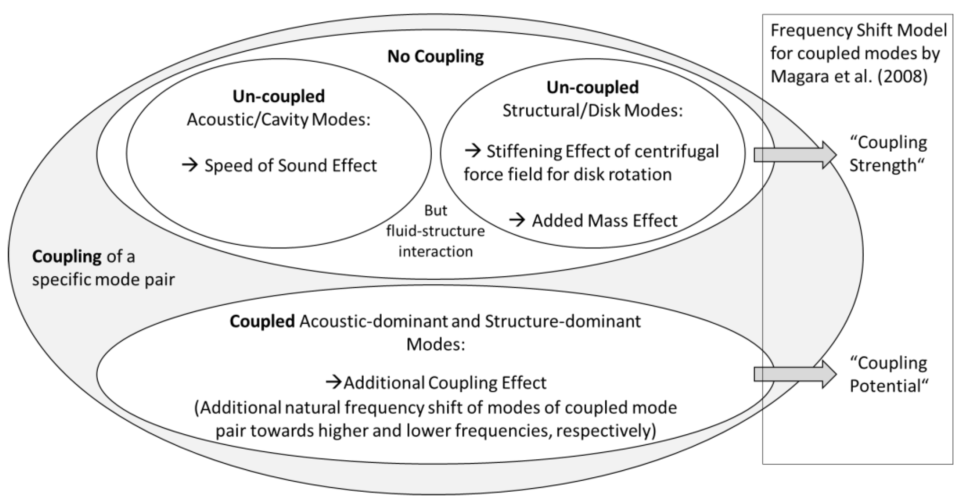
3.6. Existing Frequency Shift Models

One widely used mathematical model aiming at explaining coupling effects in rotor-cavity systems is the model of Magara et al. (2008) [12], which originates from research on frequency shifts of centrifugal compressor impellers in high-density gas applications.
The frequency shift model consists of a parabola, which opens upward (left side of Equation (7)) and a straight line with a positive slope (right side of Equation (7)) if the square of the system frequency f s 2 is indicated on the x-axis (see Figure 2).
( f 1 , u c 2 f s 2 ) ( f 2 , u c 2 f s 2 ) = 2 ρ f   c 2 ρ d   b   s c f s 2
The intersections of the parabola with the x-axis (points A) represent the theoretically uncoupled natural frequencies of the disk and the fluid. Which of them is the lower and which the higher-frequency mode depends on the geometry and cannot be stated generally. Therefore, they are not indicated as acoustic and structure modes, but as f 1 , u c and f 2 , u c . The frequency difference between A 1 and A 2 indicates the coupling potential of the two modes, being bigger the closer the theoretically uncoupled natural frequencies are to each other. The straight line indicates the coupling strength. The slope increases with an increase in fluid density ρ f and speed of sound c and decreases with an increase in disk density ρ d , disk thickness b , and axial cavity width s c . The intersections of the coupling strength term with the parabola (points B and C) represent the two natural frequencies of the coupled system f s . When the coupling strength increases, the intersections are shifted upwards and outwards, i.e., the frequency of the lower-frequency mode decreases (from B 1 to C 1 ) and the one of the higher-frequency mode increases (from B 2 to C 2 ). This frequency shift is bigger, the more the coupling strength increases (the bigger its slope), and the closer the theoretically uncoupled modes are to each other, i.e., the bigger the coupling potential. The latter effect can be illustrated by comparing the frequency shifts of the cases with weak (solid line parabola) and strong coupling potential (dashed line parabola).

3.7. Overview on Frequency Shift Phenomena in a Rotor-Cavity-System

Based on the comprehensive review of structural and acoustic modes, as well as their fluid-structure interaction and coupling in the previous paragraphs, an overview of frequency shift effects in rotor-cavity systems is presented in what follows (Figure 3).
First, there is a group of “uncoupled mode effects”, which occur independently from any coupling of a specific mode pair, i.e., they can be observed for both, uncoupled as well as for coupled modes: The speed of sound effect refers to a shift in the natural frequency of the acoustic mode if the speed of sound changes due to altered fluid properties. Additionally, the stiffening effect of the centrifugal force field might be observed for rotating impellers resulting in a slight upward shift of the structural frequency at higher rotational speeds. Considering fluid-structure interaction effects, which are of particular importance for higher fluid densities surrounding an impeller, the added mass effect plays an important role. It results in a decrease of disk frequencies if the mass of the surrounding fluid increases. In Magara’s coupling model [12], these effects are encompassed by the term “coupling strength”. If two specific modes are coupled, i.e., a structure and an acoustic dominant mode with similar mode shapes and natural frequencies in a certain proximity to each other are excited, this adds additional frequency shifts: For a coupled mode pair, one natural frequency shifts towards higher, the other towards lower frequencies, compared to their uncoupled counterparts. This is referred to as the coupling effect. The smaller the frequency difference of the uncoupled modes is, the bigger is the coupling effect, and thus the frequency shift it effectuates. In Magara’s coupling model [12], these frequency shifts are addressed by the term “coupling potential”.
Based on this, the following can be hypothesized: Any frequency shift that is not caused by the added mass, speed of sound, or stiffening effect (for uncoupled structural or acoustic modes) indicates an additional coupling effect. The coupled modes are then referred to as structure dominant and acoustic dominant modes.
When the frequency difference between two coupled modes decreases subject to, e.g., a change in fluid properties or rotational speed, the two modes approach each other. However, in several cases, they do not intersect (no resonance) but diverge again and approach the theoretically uncoupled frequency path of the other mode. This frequency deflection is called mode veering and reported, e.g., in [27,29].

4. Experimental Setup and Procedure

4.1. Test Rig and Instrumentation

Experimental results presented in this paper are obtained at the rotor-cavity test rig of the Chair of Turbomachinery at the University Duisburg-Essen, Germany, introduced in [21,22,23]. The test rig consists of a plain rotating disk with a constant width b in a cylindrical stationary casing, forming two fluid-filled cavities, which are connected through a small radial gap. A sketch of the test rig, including some measurement equipment, is given in Figure 4. This setup represents a simplified model of the side cavities in radial compressors. The axial gap widths of the front and rear cavity, s c f and s c r , respectively, can be adjusted independently. For the conducted experiments, there is no superimposed through flow in the cavities. The disk is mounted on a shaft connected to a continuously adjustable high-speed electrical drive via a magnetic coupling. Different gases can be passed into the test rig from a pre-mix chamber, allowing for a variation of fluid parameters. The disk’s rotational speed Ω can be varied, and circumferential Reynolds numbers up to 2 × 10⁸ can be achieved with CO2 at maximum speed.
Excitation sources in real turbomachinery, such as rotor-stator interaction, are missing in the test rig due to its simplified (blade- and vane-less) geometry. For that reason, a loudspeaker is installed in the casing of the front cavity. It is capable of exciting both acoustic and structure dominant modes in the front and the rear cavities. The excitation frequency is set by a wave generator connected to an amplifier and adjusted independently from other parameters. The geometry of the test rig is designed so that at least one pair of acoustic and structural modes with the same number of nodal diameters are coupled at ambient conditions.
When interpreting the results, one should notice that the cavity, in which the measurements are taken, is not perfectly closed. There are two small openings in the front cavity, one at the outer radius and one at the inner. Although valves in the connecting pipes are closed so that there is no in- or outflow to or from the cavity, these openings might affect the propagation and reflection of acoustic waves inside the cavity. In future experiments, results for a completely closed cavity and the current setup will be compared to gain further insight into this matter. However, the side cavities in real turbomachines are also not perfectly closed, so that the setup in this work might even represent a more realistic case than that of a perfectly sealed cavity.
To measure acoustic modes that occur in the form of local pressure fluctuations, the test rig is equipped with two pressure transducers in each, the front and rear cavity, as well as one on the disk. To detect structural modes in the form of disk vibration, two strain gauges are mounted on the disk. The following measures are provided for the identification of mode shapes: The number of nodal diameters of the excited mode is traced with an additional traversable pressure sensor installed in the front cavity, which can rotate 300 degrees around the disk’s circumference at a constant excitation frequency. To detect the number of nodal circles, the two pressure sensors in the front cavity are mounted at a different radial position compared to those in the rear cavity. An axial node is detected by identifying a 180 degrees’ phase shift between the pressure patterns in the front and rear cavity. In addition, the test rig and pre-mix chamber are equipped with pressure and temperature sensors to determine the thermodynamic properties of the fluid.
The general uncertainty of the measurement chain of the temperature sensors is determined to be ±1.8 K, and the non-linearity and dynamic uncertainties of the pressure sensors are negligibly small [29]. However, strain gauges are only able to measure dynamic vibrations up to a cut-off frequency of 50 kHz [29]. Additionally, the electrostatic noise increases significantly for experiments with a rotating disk, resulting in a very low signal-to-noise ratio for those strain gauge results. However, pressure sensor results are not affected as much by electromagnetic interferences. Therefore, response functions for the structure dominant modes are also measured with pressure sensors in case of disk rotation. Measurements without disk rotation have shown that this approach does not influence the results as strain gauge and pressure sensor measurements agree well.

4.2. Experimental and Evaluation Procedures

In preparation for the experiments, the test rig is filled with the required gas mixture until the target pressure is reached. The temperature inside the test rig is assumed to be constant, as a maximum friction-induced increase of 0.3% for experiments with high rotational speeds is considered negligible.
All experiments aiming to identify the modal parameters of the excited modes are conducted through frequency sweep experiments. First, the frequency interval and sweep velocity are set. The latter is chosen sufficiently small so that the transducer’s response can be considered stationary. The frequency generator produces the respective harmonic signal, amplified to drive the loudspeaker acting as the excitation source. Sweep experiments are conducted with a constant sweep velocity from low to high frequencies and the rotatable pressure sensor set to a fixed position. Each frequency sweep experiment is repeated three times.
Additional measurements with the rotatable pressure sensor are conducted at a constant excitation frequency for mode order identification. The rotatable pressure sensor traverses to different circumferential positions, where it remains for the duration, during which pressure fluctuations are measured at this position. In this way, pressure patterns in circumferential direction are identified, and the number of nodal diameters is determined. Moreover, a coupled finite element method analysis and an experimental hammer test of the disk have been conducted to have a reference for the modal parameters of the disk vibration modes.
The data from the pressure transducers and strain gauges recorded during the sweep experiments are evaluated by Fourier transformation. Thereby, the raw data is transformed from the time into the frequency domain, and frequency response functions are obtained for each sensor. Natural frequency results are obtained using the peak picking method. However, especially for acoustic dominant modes in the “slim cavity” setup, many modes overlap, influence, cross, and deflect each other. Moreover, interference signals influence the measured frequency response, so that frequency peaks cannot always be identified undoubtedly.

4.3. Conducted Experiments

Experiments are conducted with two different geometrical setups. For both, the rear cavity has a non-dimensional axial gap width of 0.1. The front cavity width in the “wide cavity” setup is symmetrical to the rear cavity, while for the “slim cavity” it has a non-dimensional axial gap width of 0.025. As shown in the following, the front cavity is the “dominant” one, determining the formation of acoustic (dominant) modes, likely because the excitation source is located here.
Different experimental series are conducted, aiming to reveal natural frequency shifts due to different effects discussed theoretically beforehand. In the first test series, “GAP”, a brief comparison of results for different axial gap widths is presented. A change in geometry causes a change in coupling strength by altering the fluid mass acting on the disk. In the second test series “PRESSURE”, the fluid pressure in the cavity is changed, effectuating the coupling strength. Density and speed of sound of the fluid change at the same time. Therefore, an added mass and speed of sound effects are expected. While the first two experimental series are conducted with a non-rotating disk, the third one, “ROTATION”, includes experiments with different disk rotational speeds, changing the coupling potential between modes by altering the frequency difference between them. Through this, the coupling potential is expected to be significantly increased, resulting in much stronger coupling effects than for the previous test series. An overview of the conducted experimental series is given in Table 1.
Based on the preceding remarks, two main hypotheses are stipulated:
  • Any frequency shift that cannot be explained by “uncoupled mode effects” is presumably due to additional coupling effects;
  • The coupling effect is stronger the closer the natural frequencies of the theoretically uncoupled modes are to each other.
To validate these hypotheses, the experimental results in this work are assessed subject to the following approach:
  • Theoretic frequency shifts of “uncoupled mode effects” are quantified and measured frequency shifts corrected for their influence;
  • The remaining frequency shifts are analyzed, which are expected to be due to “coupling effects”.

4.4. Estimation of Coupling Effect

To estimate the coupling effect, i.e., the extent of any frequency shift caused by coupling, a coupling potential parameter C P and a coupling strength parameter C S are introduced as follows:
C P = f a c f s t min ( f a c , f s t )
C S = ρ f   c s c f
The coupling potential parameter C P represents the frequency separation between the coupled modes. A smaller value indicates stronger coupling. It is positive when the acoustic dominant mode has a higher frequency than the structure dominant one, and negative if it is vice versa. In the following, the coupling potential is defined as “strong” when the frequency separation between the structure and acoustic dominant modes is less than 0.3. The coupling strength parameter C S depends on the fluid properties as well as the geometry of the cavity. Both coupling parameters together allow concluding on a possible coupling effect.

4.5. Presentation of Measurement Results

Measurement results are presented in the following way: Instead of absolute natural frequencies f s t and f a c , normalized frequencies f are used in the following, which are frequencies relative to that of the two nodal diameter structure mode in air for the “slim cavity” setup, which serves as a reference frequency f r e f , as follows:
f = f f r e f = f f s t , 2 , 0 ( a i r , 0.1   MPa , 295   K )
Normalized frequencies f can be calculated for any structure (dominant) mode (m,n) and any acoustic (dominant) mode (p,q,r).
For the evaluation of frequency shifts, relative frequency changes Δ f are displayed. These are frequency changes relative to the frequency at a cavity pressure of 0.1 MPa as follows:
Δ f = f f 0 f 0 = f f ( 0.1   MPa ) f ( 0.1   MPa )
Corrected relative frequency changes Δ f s t , c o r r of structural modes (corrected for the added mass effect) are calculated as follows, with m t o t = m d + m f being the total mass of disk and fluid together:
Δ f s t , c o r r ( ρ ) = f s t , c o r r ( ρ ) f s t , 0 f s t , 0 = f s t ( ρ ) m t o t ( ρ ) m t o t , 0 f s t , 0 f s t , 0
Corrected relative frequency changes Δ f a c , c o r r of acoustic modes (corrected for the speed of sound effect) are calculated as follows:
Δ f a c , c o r r ( ρ ) = f a c , c o r r ( ρ ) f a c , 0 f a c , 0 = f a c ( ρ ) c 0 c ( ρ ) f a c , 0 f a c , 0
Corrected relative frequency changes Δ f s t , c o r r and Δ f a c , c o r r can be calculated for any structure (dominant) mode (m,n) and any acoustic (dominant) mode (p,q,r), respectively.

5. Measurement Results and Discussion

Acoustic and structure dominant modes that can be excited in the test rig within the range of analyzed frequencies (150 s−1 to 1400 s−1) are the two to five nodal diameter modes with zero nodal circles. Following the theory of a match of mode shapes [10], only modes with the same mode order are considered as potentially coupled ( m = p , n = q ). Coupled acoustic dominant modes have an additional axial node ( r = 1 ), so that there is a net force acting on the disk. For all analyzed mode pairs, except for the five nodal diameters one in the “slim cavity”, the acoustic dominant mode has a higher frequency than the structure dominant mode. This, along with other characteristic data of the occurring mode pairs, is displayed in Table 2.
The different geometries of the two test rig setups result in slightly different core rotation factors k 0 and thereby different coupling strength parameters C S . The latter is also controlled by the fluid properties. The frequency separation between the theoretically uncoupled structure and acoustic modes with the same number of nodal diameters determines the coupling potential parameter C P . Both coupling parameters then predict the coupling effect. In Table 2, coupling strength parameters C S are exemplarily given for 0.1 MPa and 295 K, and coupling potential parameters C P for standstill of the disk.
From this preliminary estimation of the coupling effect, the coupling strength is expected to be bigger for the “slim cavity” test rig setup compared to the “wide” one; and lower in Helium compared to air. The coupling potential is estimated to be the biggest for the four nodal diameter mode in air for the “wide cavity” setup, followed by the five and four nodal diameter modes in the “slim cavity”. For these mode pairs, frequency shifts are expected to be observable due to the strong coupling potential.
Results of the three different test series (as introduced in Table 1) are presented in the following.

5.1. Variation of Axial Gap Width

In the first experimental series, “GAP”, the axial gap width of the front cavity is varied and thereby is the coupling strength. The disk is non-rotating. With a decrease in (front) cavity width, the fluid mass acting on the disk decreases, and the coupling strength increases (see Table 2 for CS values).
Response functions recorded for the different front cavity widths differ considerably from each other. With a decrease in the cavity width, the natural frequencies of the structure dominant modes change only slightly (max 2%), while the acoustic dominant modes shift significantly towards higher frequencies (5% to 25%). Therefore, it can be concluded that the axial gap width has a significant influence on the occurring acoustic dominant modes. Additionally, more peaks appear to occur in the response functions, and many peaks overlap in the measurements with a smaller front cavity width.
The measured natural frequencies do not reflect the theoretically expected behavior if no coupling is anticipated (slight increase in disk natural frequencies and no change in acoustic dominant modes), neither do they exhibit the expected frequency shifts if coupling is assumed. Consequently, neither the “uncoupled mode effects” nor the coupling models can explain the observed frequency shifts subject to a variation of the axial gap width, i.e., the theory does not explain the measurement results.

5.2. Presure Variation

In the second experimental series “PRESSURE”, with a non-rotating disk, the fluid pressure inside the test rig is changed while all other parameters remain constant. Thereby, the coupling strength is varied (for CS values at 0.1MPa see Table 2), and added mass as well as speed of sound effects are expected to influence measured natural frequencies. In addition, a weak coupling effect might be observable, depending on the excited mode pair (see CP values in Table 2). For all measurement results of the series “PRESSURE”, corrected relative frequency changes Δ f c o r r are displayed as defined in Equations (11)–(13).
A measurement series using the “wide cavity” setup and helium as the fluid is conducted as disk vibration modes measured in helium can be considered approximately uncoupled due to the big frequency separation to the respective acoustic modes (see Table 2). If no further coupling is assumed, the frequencies should not change subject to a change in fluid density after being corrected for the added mass effect. As shown in Figure 5, natural frequencies of the measured three and four nodal diameter structure modes decrease slightly with an increase in fluid density. Corrected for the added mass effect, an insignificant decrease of 0.3% and 0.2% remains for the (3,0) and (4,0) structural modes, respectively, if the fluid density is increased approximately 15-fold. This remaining decrease in frequency is considered as negligible, and therefore these modes in helium can be considered as practically constant and thus uncoupled.
Measurements using the “slim cavity” setup and air as the fluid are conducted to analyze the excited modes for potential coupling. As mode pairs in air exhibit a higher coupling potential than those in helium, frequency shifts attributed to coupling effects are expected to be bigger in air, but dependent on the coupling potential of each mode pair. Corrected relative frequency changes of the structure dominant modes Δ f s t , c o r r are presented in Figure 6. For the modes with two to four nodal diameters, the natural frequencies of the disk decrease about 4% to 5% for a 12-fold increase in fluid density, while the frequency of the five nodal diameter structural mode increases about 5%. These frequency changes are considerably bigger than those measured in the almost uncoupled case for helium, and it can be concluded that there must be an additional coupling effect. Measured frequency shifts agree qualitatively with the coupling model of Magara et al. (2008) [12], indicating a decrease in the frequency of the structure dominant modes in case of f s t < f a c , and an increase for the opposite case (for the five nodal diameter mode). However, the frequency changes appear to be very similar for the two, three and four nodal diameter modes, although those have different coupling potentials.
While most frequency peaks are well visible for structural modes, this is not the case for most acoustic modes; the two nodal diameter mode is the only exception. To show potential coupling influences, both (acoustic and structure dominant) modes of the two nodal diameter mode pair are displayed in Figure 7. After the structural mode is corrected for the added mass effect and the acoustic mode for the speed of sound effect, both still exhibit a decreasing and a slightly increasing trend, respectively, when plotted over the fluid density. This behavior supports the hypothesis that weak coupling is present between the disk and the surrounding fluid, and the trends agree qualitatively with those in Magara’s [12] coupling model.
It should be noted that the frequency change of the acoustic dominant mode differs slightly depending on the pressure sensor’s location in the test rig. It is smaller (+2.2% (S9) and +1.3% (S8 on disk)) than that of the structure dominant mode (−5.5%) for the approximately 14-fold increase in density.
Altogether, for the measurement series “PRESSURE”, frequency shifts of structure dominant modes are observed that exceed the “uncoupled mode effects” and thus indicate a coupling effect, even for modes that are only weakly coupled. However, no clear picture about frequency shifts of acoustic dominant modes is obtained, and the hypothesis of a more pronounced coupling effect for stronger coupled modes could not be confirmed on the base of the measurement series with a variation in fluid pressure.

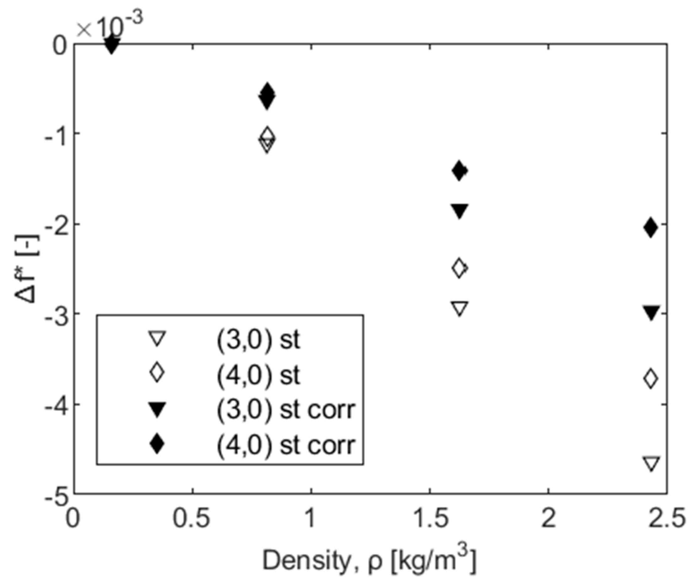
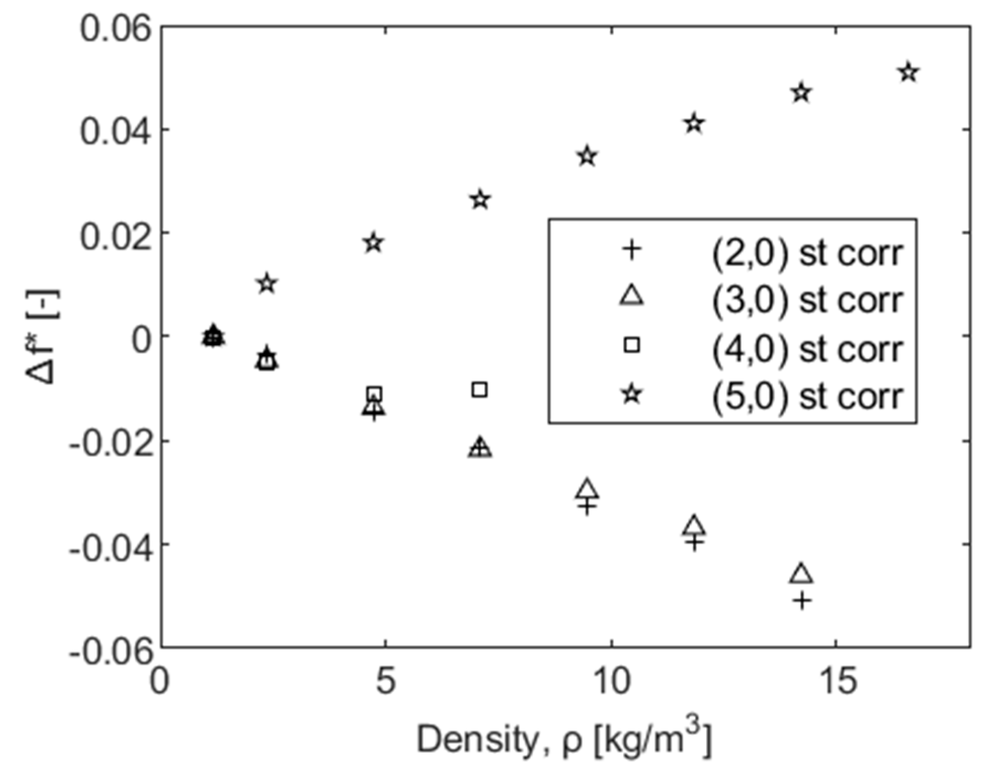
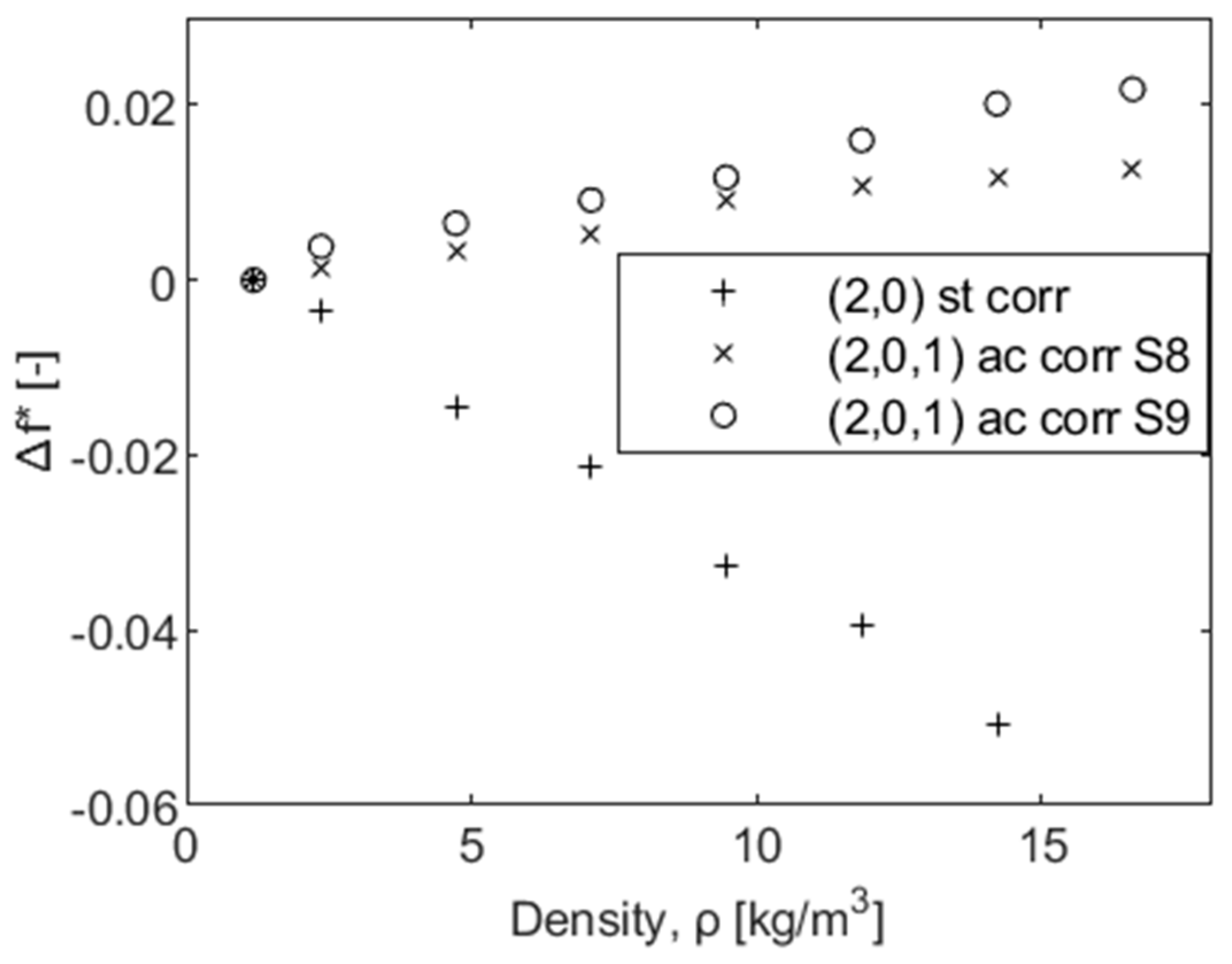
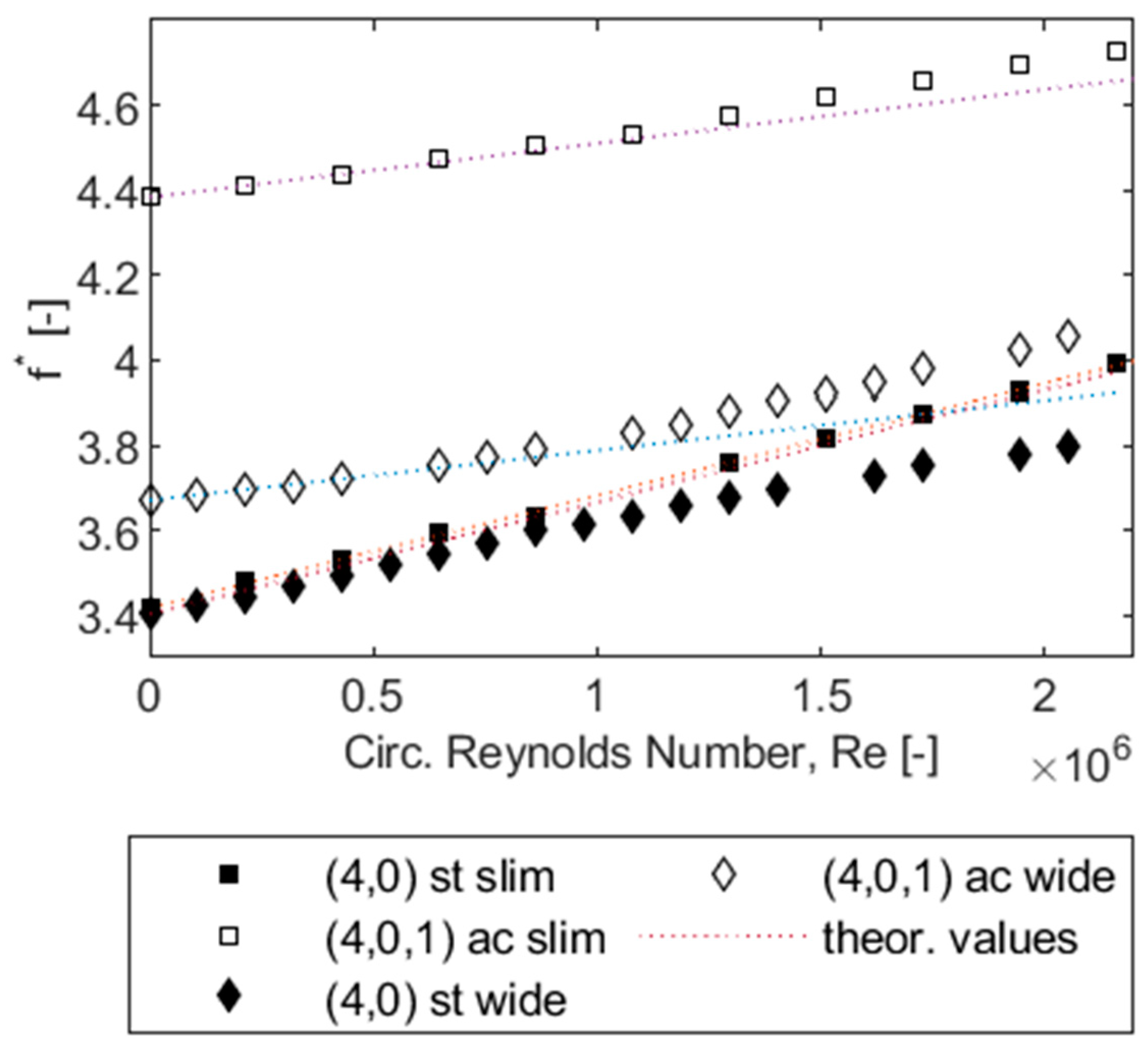
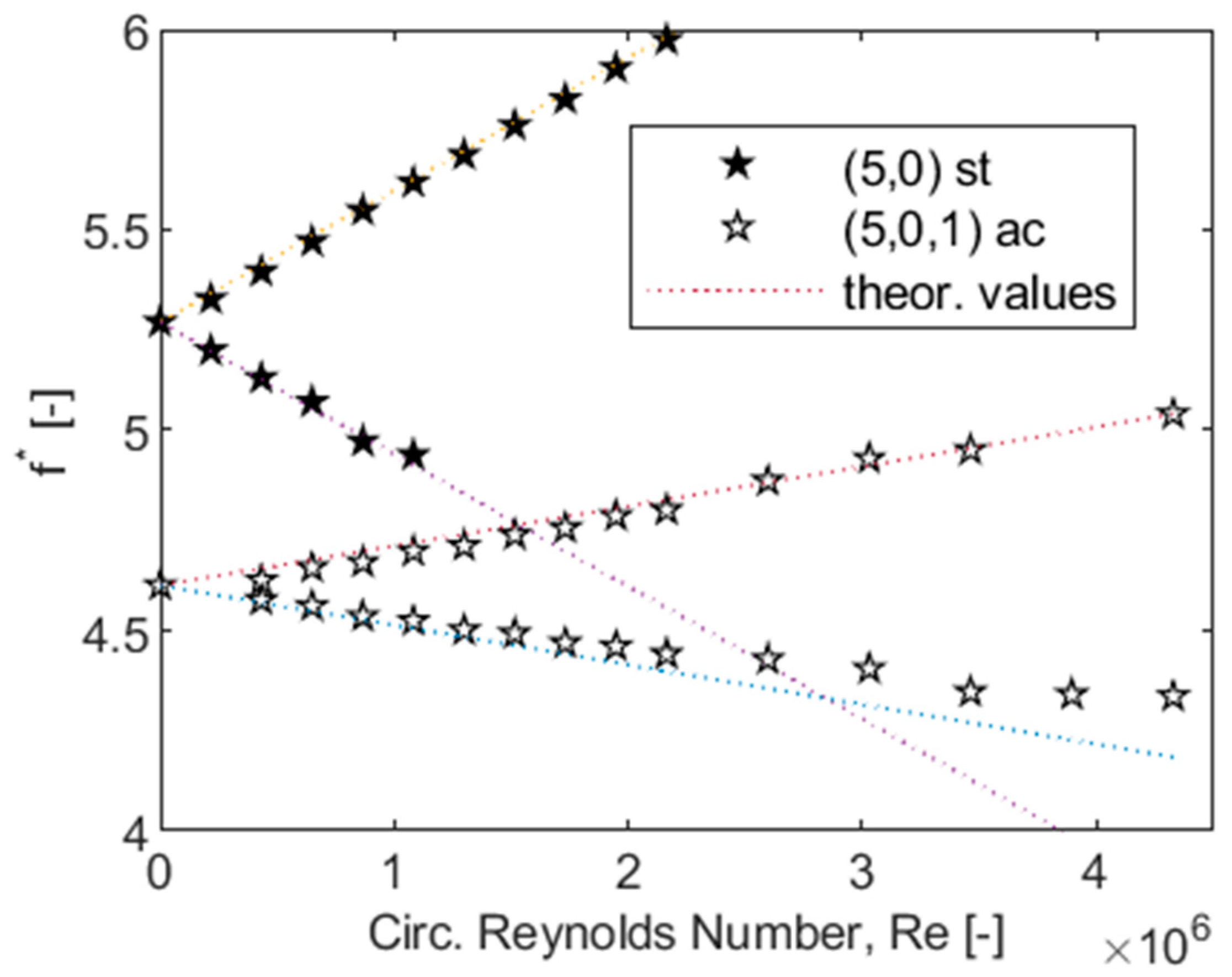
5.3. Variation of Disk Rotational Speed

In the third experimental series, “ROTATION”, the disk rotational speed is varied, while the fluid pressure (0.1 MPa, air) and all other parameters remain constant. By this means, the coupling potential is changed as frequency differences between potentially coupled acoustic and structure dominant modes are varied (rotating case C P values differ from standstill values in Table 2). There is no added mass or speed of sound effect. However, a small effect of the stiffening effect of the centrifugal force field of the impeller might be observable, but measurement values are not explicitly corrected for its influence.
Disk rotation results in the formation of two modes for each mode order, one forward and one backward traveling wave. While disk modes theoretically travel at the disk rotational speed, cavity modes travel at the fluid’s rotational speed in the cavity. Assuming bulk flow in the cavity at approximately half the disk’s rotational speed, frequencies of acoustic and structure dominant modes approach each other subject to a change in disk rotational speed. These effects are shown in the following, first for structure, then for acoustic dominant modes, and last for specific mode pairs. For all measurement results of the series “ROTATION”, normalized frequencies f are displayed as defined in Equation (10). In addition to the measurement results, theoretical values for the natural frequencies of structure and acoustic dominant modes at the respective disk rotational speed are given, calculated according to Equations (2) and (6), respectively. Utilized core rotation factors for the acoustic dominant modes are listed in Table 2.
As shown in Figure 8, the development of a forward and a backward traveling wave is clearly visible for each mode, and the measured frequency splits of the disk vibration modes subject to rotation agree well with the theoretical values.
Natural frequencies of the acoustic dominant modes are much less apparent in the measurement results than the disk vibration modes, as they are often overlapping with neighboring modes or deflected by them. However, the formation of a forward and a backward traveling wave is evident for the acoustic dominant modes with three, four, and five nodal diameters, as shown in Figure 9. Measured and theoretic frequency splits of the acoustic dominant modes subject to disk rotation do not agree well. Moreover, there is no consistent trend noticeable; measured frequency splits for the (3,0,1) and the (5,0,1) modes are smaller than the theoretical values, while the frequency split of the (4,0,1) mode is slightly bigger. Moreover, core rotation factors adopted to match theoretic values of the three and five nodal diameter acoustic waves with the experimental ones appear to be outside of the usual range. Possibly, the core rotation factors are different from the ones calculated theoretically from Equation (5). Additionally, the number of nodal diameters might influence the natural frequency of the traveling waves, in a way different from that stated in Equations (3) and (6). However, for all analyzed modes, the forward wave appears to exhibit a bigger frequency difference to the non-rotating case than the backward wave.
To assess the coupling effect for coupled mode pairs, the respective acoustic and structure dominant modes are presented together in the following. Disk rotation further increases the coupling potential (compared to the standstill values in Table 2), making coupling effects observable. The mode pair with three nodal diameters (displayed in Figure 10) is very well visible for all analyzed rotational speeds. However, the coupling potential is estimated to be low ( C P = + 0.9 ), and thus the expected coupling effect relatively small. Theoretically, the forward traveling waves of the structure and acoustic dominant modes would cross at very high disk rotational speeds while the backward waves veer away from each other. However, within the range of analyzed rotational speeds, the coupling potential remains weak. If the theoretic values are adjusted to approximately fit the backward wave of the measured acoustic dominant mode, which is assumed to be less influenced by coupling, a core rotation factor of about 0.25 must be adopted (as shown in Figure 10). Compared to the backward wave, the acoustic dominant forward wave appears to be deflected towards higher frequencies. This might be due to the increased but still relatively small coupling potential at higher rotational speeds.
The strongest coupling potential of all measured modes is predicted for the four nodal diameter mode pair in the “wide cavity” test rig setup ( C P = + 0.08 ). Therefore, frequency shifts due to the strong coupling effect are expected to be observable. As can be seen in Figure 11, mode veering is visible, confirming this assumption. The forward modes strongly influence and deflect each other. Instead of crossing at a circumferential Reynolds number of approximately 1.7 × 10⁶, the forward traveling waves approach each other until a minimum normalized frequency difference of 0.2 is reached and then veer apart, increasing their frequency separation again. For the “slim cavity” test rig setup, this behavior cannot be observed, as the acoustic dominant mode is shifted towards higher frequencies resulting in a weaker coupling potential ( C P = + 0.28 ). The structure dominant mode follows the theoretical values well, and the acoustic dominant one only exhibits a slight upward deflection. This is a clear indication that a stronger coupling effect is present for stronger coupled modes, i.e., those in closer proximity to each other.
The four and five nodal diameter mode pairs, which are estimated to be strongly coupled in the “slim cavity” setup ( C P values of +0.28 and −0.14, respectively, see Table 2), are not very well visible in the measurement results. With disk rotation, the coupling potential becomes even bigger, but the response peaks of the structure dominant modes are poorly visible and diminish at a certain rotational speed. As shown in Figure 12, the backward wave of the structure dominant five nodal diameter mode disappears once it comes close to the forward acoustic wave and therefore does not come in closer proximity to the potentially coupled backward acoustic dominant wave. The same happens for the forward wave of the structure dominant four nodal diameter mode, which is no longer visible at Reynolds numbers higher than 2 × 10⁶, where it crosses the backward wave of the acoustic dominant mode (see Figure 8 and Figure 9). Therefore, it does not come close to the coupled forward wave of the acoustic dominant mode. Consequently, no conclusion on the coupling effect and possible veering behavior of the modes with a strong coupling potential can be drawn for the “slim cavity” test rig setup.
Nevertheless, it should be noted that the concept of bulk flow inside the cavity that can be estimated by a core rotation factor is a theoretical idea that does not exist in real cavities. Moreover, measurement results presented in this work are characterized by circumferential Reynolds numbers slightly lower than values for well-established bulk flow. Therefore, most measurement results actually classify into the transitions area between merged and separated boundary layer regimes according to [25], and the applicability of the core rotation concept should be further investigated. Using a fluid with lower kinematic viscosity or conducting measurements with disk rotation at higher pressures could be options to reach higher Reynolds numbers in future experiments.

6. Conclusions and Future Work

In the first part, fundamental concepts necessary to understand the formation of structural and acoustic modes and their coupling in a rotor-cavity system are compiled, and existing coupling models are reviewed. Based on a comprehensive literature review, an overview of frequency shift effects in rotor-cavity systems with a rotating disk is established, including effects for uncoupled and coupled modes. A procedure to analyze those frequency shift effects is developed and later applied to the analysis of experimental results. Moreover, an attempt to quantify the expected coupling effects is made by establishing a coupling strength and a coupling potential parameter.
In the second part of this work, measurement results of acoustic and structure dominant modes are presented, including a test series with varying cavity pressure and one with different disk rotational speeds. For the latter, the development of a forward and a backward traveling wave is demonstrated for each mode. All excited mode pairs in the test rig are at least weakly coupled in air, i.e., frequency shifts are observed that cannot solely be explained by “uncoupled mode effects”, such as the added mass, speed of sound, and stiffening effect, but indicate an additional coupling effect. However, the hypothesis of a bigger coupling effect (bigger frequency shift) for stronger coupled modes cannot be corroborated consistently. By varying the disk rotational speed, the frequency difference between coupled modes, and thus their coupling potential, can be varied additionally. However, the expected coupling effect is not observable for all mode pairs. Only the four nodal diameter mode pair in the “wide cavity” exhibits a strong coupling effect. Mode veering is visible, i.e., with an increase in disk rotational speed, the coupled modes approach each other, and then veer apart instead of crossing.
Generally, measurement results for structure dominant modes agree well with theoretical predictions. However, measured acoustic dominant modes do not always exhibit the expected theoretic behavior. It requires further research to clarify whether or not the underlying assumptions on core rotation apply to the flow conditions in the cavity during the measurements. For future research, a different fluid or a higher pressure could be considered to ensure higher Reynolds numbers and further validate the bulk flow concept as well as examine boundary layer influences. Additionally, the influence of the small opening of the cavity needs further investigation.
The next essential step in the line of this research will be to investigate the damping of coupled acoustic and structure dominant modes, as resonances cannot always be avoided and the damping ratio determines the response amplitudes of the system and thus the risk of impeller material failure. Eventually, the transferability of the results to real machines needs to be proven. However, this work poses an essential step towards a better understanding of acoustoelastic coupling effects in the side cavities of centrifugal compressors under varying operating conditions.

Author Contributions

Conceptualization, T.U.; Data curation, T.U.; Formal analysis, T.U.; Funding acquisition, D.B.; Investigation, T.U.; Methodology, T.U.; Supervision, D.B.; Visualization, T.U.; Writing—original draft, T.U.; Writing—review & editing, D.B. All authors have read and agreed to the published version of the manuscript.

Funding

This project is funded by Deutsche Forschungsgemeinschaft (DFG). The authors are grateful for the financial support under project number 429153912.

Data Availability Statement

Not applicable.

Conflicts of Interest

The authors declare no conflict of interest. The funders had no role in the design of the study; in the collection, analyses, or interpretation of data; in the writing of the manuscript, or in the decision to publish the results.

Nomenclature

b disk/impeller thickness, m
c speed of sound, m/s
c f friction coefficient
C P coupling potential parameter
C S coupling strength parameter
f frequency, 1/s
f = f f r e f normalized frequency relative to the frequency f r e f = f s t , 2 , 0 ( a i r ,   0.1   MPa , 295   K )
Δ f = f f 0 f 0 relative frequency change relative to the frequency f 0 = f ( 0.1   MPa )
f rotational frequency of rotating disk, 1/s
G = s r d non-dimensional axial gap width of cavity
k 0 core rotation factor
L characteristic length, m
m mass, kg
( m , n ) number of nodal diameters, nodal circles of structure (dominant) mode
( p , q , r ) number of nodal diameters, nodal circles, axial nodes of acoustic (dominant) mode
r radius, m
R e circumferential Reynolds number
s axial gap width of cavity, m
t a x cylindrical portion of impeller side room, m
u disk/impeller circumferential velocity, m/s
v velocity, m/s
Ω rotational speed of disk, 1/min
( π α ) p , q dimensionless solutions to the first derivative of the Bessel function for the (p,q) acoustic mode
ν kinematic viscosity of the fluid, m2/s
ρ density, kg/m3
Subscripts
a c acoustic (dominant)
c , c f , c r cavity, front cavity, rear cavity
c o r r corrected
d disk
e excitation
f fluid
s system
s t structure (dominant)
t o t total
u c uncoupled

References

  1. Lamb, H.; Southwell, R.V. The vibrations of a spinning disk. Proc. R. Soc. A 1921, 99, 272–280. [Google Scholar]
  2. Southwell, R.V. On the free transverse vibrations of a uniform circular disc clamped at its centre; and on the effects of rotation. Proc. R. Soc. A 1922, 101, 133–153. [Google Scholar]
  3. Campbell, W. Protection of Steam Turbine Disk Wheels from Axial Vibration; General Electric Company: New York, NY, USA, 1924. [Google Scholar]
  4. Eversman, W.; Dodson, R.O., Jr. Free vibration of a centrally clamped spinning circular disk. AIAA J. 1969, 7, 2010–2012. [Google Scholar] [CrossRef]
  5. Ewins, D.J. Vibration characteristics of bladed disc assemblies. J. Mech. Eng. Sci. 1973, 15, 165–186. [Google Scholar] [CrossRef]
  6. Irretier, H. The natural and forced vibrations of a wheel disc. J. Sound Vib. 1983, 87, 161–177. [Google Scholar] [CrossRef]
  7. Irretier, H. Experiments and calculations on the vibrations of rotating radial impellers. J. Vib. Acoust. Stress Reliab. 1988, 110, 137–142. [Google Scholar] [CrossRef]
  8. Tyler, J.M.; Sofrin, T.G. Axial Flow Compressor Noise Studies; No. 620532. SAE Trans. 1962, 70, 309. [Google Scholar]
  9. Ehrich, F.F. Acoustic resonances and multiple pure tone noise in turbomachinery inlets. J. Eng. Power 1969, 91, 253–262. [Google Scholar] [CrossRef]
  10. Eisinger, F.L. Acoustic fatigue of impellers of rotating machinery. J. Press. Vessel. Technol. 2002, 124, 154–160. [Google Scholar] [CrossRef]
  11. Eisinger, F.L.; Sullivan, R.E. Acoustically-induced structural fatigue of impeller discs: A Brief Note. Turbo Expo Power Land Sea Air 2002, 3610, 1063–1069. [Google Scholar]
  12. Magara, Y.; Mitsuhiro, N.; Kazuyuki, Y.; Naohiko, T.; Tetsuya, K. Natural frequencies of centrifugal compressor impellers for high density gas applications. ASME Int. Mech. Eng. Congr. Expo. 2008, 48661, 107–114. [Google Scholar]
  13. Magara, Y.; Yamaguchi, K.; Miura, H.; Takahashi, N.; Narita, M. Natural frequency shift in a centrifugal compressor impeller for high-density gas applications. J. Turbomach. 2013, 135, 011014. [Google Scholar] [CrossRef]
  14. Beirow, B.; Kühhorn, A.; Figaschewsky, F.; Nipkau, J. Effect of mistuning and damping on the forced response of a compressor blisk rotor. ASME Turbo Expo 2015: Turbine Technical Conference and Exposition. Am. Soc. Mech. Eng. Digit. Collect. 2015, 56772, V07BT32A001. [Google Scholar]
  15. Heinrich, C.R.; Kühhorn, A.; Steff, K.; Petry, N. Generalized Model for the Approximation of Coupled Acousto-Mechanical Natural Frequencies in High-Pressure Centrifugal Compressors. J. Eng. Gas Turbines Power 2021, 143, 071022. [Google Scholar] [CrossRef]
  16. Heinrich, C.R.; Unglaube, T.; Beirow, B.; Brillert, D.; Steff, K.; Petry, N. Surrogate Models for The Prediction of Damping Ratios in Coupled Acoustoelastic Rotor-Cavity Systems. In Proceedings of the ASME Turbo Expo 2021: Turbine Technical Conference and Exposition, online, 7–11 June 2021. GT2021-58835. [Google Scholar]
  17. Hellmich, B.; Seume, J.R. Causes of acoustic resonance in a high-speed axial compressor. ASME Turbo Expo 2006: Power for Land, Sea, and Air. Am. Soc. Mech. Eng. Digit. Collect. 2006, 4241, 377–387. [Google Scholar]
  18. König, S. Acoustic eigenmodes in the side cavities of centrifugal compressors. Turbo Expo Power Land Sea Air 2009, 48876, 547–557. [Google Scholar]
  19. Petry, N.; König, S.; Benra, F.-K. Influence of the Swirling Flow in the Side Cavities of a High-Pressure Centrifugal Compressor on the Characteristics of Excited Acoustic Modes. Turbo Expo Power for Land, Sea, and Air. Am. Soc. Mech. Eng. 2012, 44748, 627–639. [Google Scholar]
  20. Eckert, L. High Cycle Fatigue Cracks at Radial Fan Impellers Caused by Aeroelastic Self-Excited Impeller Vibrations: Part I—Case History, Root Cause Analysis, Vibration Measurements. International Design Engineering Technical Conferences and Computers and Information in Engineering Conference. Am. Soc. Mech. Eng. 1999, 19777, 1135–1146. [Google Scholar]
  21. Barabas, B.; Stefan, C.; Sebastian, S.; Friedrich-Karl, B.; Hans-Josef, D.; Dieter, B. Experimental and numerical determination of pressure and velocity distribution inside a rotor-stator cavity at very high circumferential Reynolds numbers. In Proceedings of the 11th European Conference on Turbomachinery Fluid dynamics & Thermodynamics, Madrid, Spain, 23–27 March 2015. [Google Scholar]
  22. Barabas, B.; Dieter, B.; Hans-Josef, D.; Friedrich-Karl, B. Identification of Coupled Natural Frequencies in a Rotor-Stator Test-Rig for Different Gas Properties. In Proceedings of the 12th European Conference on Turbomachinery Fluid dynamics & Thermodynamics, Stockholm, Sweden, 3–7 April 2017. [Google Scholar]
  23. Barabas, B.; Dieter, B.; Hans-Josef, D.; Friedrich-Karl, B. Damping Behavior of Acoustic Dominant Modes in an Aeroacoustic Test Rig Representing a Simplified Geometry of a High Pressure Radial Compressor. Turbo Expo: Power for Land, Sea, and Air. Am. Soc. Mech. Eng. 2018, 51159, V07CT36A018. [Google Scholar]
  24. Norton, M.P.; Frederick, C.N. Fundamentals of Noise and Vibration Analysis for Engineers; Cambridge University Press: Cambridge, UK, 1998. [Google Scholar]
  25. Daily, J.W.; Nece, R.E. Chamber dimension effects on induced flow and frictional resistance of enclosed rotating disks. J. Basic Eng. 1960, 82, 217–230. [Google Scholar] [CrossRef]
  26. Gülich, J.F. Disk friction losses of closed turbomachine impellers. Forsch. Im Ing. 2003, 68, 87–95. [Google Scholar] [CrossRef]
  27. Sigrist, J.-F.; Daniel, B.; Christian, L. Dynamic analysis of a nuclear reactor with fluid–structure interaction: Part i: Seismic loading, fluid added mass and added stiffness effects. Nucl. Eng. Des. 2006, 236, 2431–2443. [Google Scholar] [CrossRef]
  28. Fahy, F.J. Vibration of containing structures by sound in the contained fluid. J. Sound Vib. 1969, 10, 490–512. [Google Scholar] [CrossRef]
  29. Barabas, B.; Friedrich-Karl, B.; Nico, P.; Dieter, B. Experimental Damping Behavior of Strongly Coupled Structure and Acoutic Modes of a Rotating Disk with Side Cavities. In Proceedings of the ASME Turbo Expo 2021: Turbine Technical Conference and Exposition, online, 7–11 June 2021. GT2021-58782. [Google Scholar]
Figure 1. Non-dimensional solutions to Bessel functions for acoustic frequencies inside a cylinder and respective mode shapes for different numbers of nodal diameters and nodal circles.
Ijtpp 07 00015 g001
Figure 2. Coupling model of Magara et al. (2008) [12].
Ijtpp 07 00015 g002
Figure 3. Overview of frequency shift effects in rotor-cavity systems [12].
Ijtpp 07 00015 g003
Figure 4. Test rig setup and measurement equipment.
Ijtpp 07 00015 g004
Figure 5. Corrected relative frequency changes of structure modes in helium for “wide cavity” over fluid density. Raw values and values corrected for added mass effect.
Ijtpp 07 00015 g005
Figure 6. Corrected relative frequency changes of structure dominant modes in air for “slim cavity” over fluid density. Values corrected for added mass effect.
Ijtpp 07 00015 g006
Figure 7. Corrected relative frequency changes of two nodal diameter mode pair in air for “slim cavity” over fluid density. Values corrected for added mass effect and speed of sound effect, respectively. Sensors: S8 on disk, S9 in front cavity.
Ijtpp 07 00015 g007
Figure 8. Normalized natural frequencies of structure dominant modes in air at 0.1MPa for “slim cavity” over circumferential Reynolds number. Experimental and theoretical results.
Ijtpp 07 00015 g008
Figure 9. Normalized natural frequencies of acoustic dominant modes in air at 0.1MPa for ”slim cavity” over circumferential Reynolds number. Experimental and theoretical results.
Ijtpp 07 00015 g009
Figure 10. Normalized natural frequencies of three nodal diameter mode pair in air at 0.1MPa for “slim cavity” over circumferential Reynolds number. Experimental and theoretical results (a core rotation factor of 0.25 is adopted for the theoretic values of the acoustic wave).
Ijtpp 07 00015 g010
Figure 11. Normalized natural frequencies of forward waves of four nodal diameter mode pair in air at 0.1 MPa for “wide” and “slim cavity” over circumferential Reynolds number. Experimental and theoretical results (core rotation factors of 0.44 and 0.48 are adopted for the theoretic values of the acoustic waves for “slim” and “wide cavity” setup, respectively).
Ijtpp 07 00015 g011
Figure 12. Normalized natural frequencies of five nodal diameter mode pair in air at 0.1 MPa for “slim cavity” over circumferential Reynolds number. Experimental and theoretical results (a core rotation factor of 0.30 is adopted for the theoretic values of the acoustic wave).
Ijtpp 07 00015 g012
Table 1. Overview of conducted test series and expected frequency shift effects.
Test SeriesDescriptionAltered Coupling
Influence
Expected Frequency Shift
Effect(s) for Uncoupled Modes
Possible Further Frequency Shift Due to Coupling
“GAP”Variation of axial gap widthVariation of coupling strengthAdded mass effectWeak coupling effect
“PRESSURE”Variation of fluid pressureVariation of coupling strengthAdded mass effect, speed of sound effectWeak coupling effect
“ROTATION”Variation of disk rotational speedVariation of coupling potentialStiffening effect of centrifugal force fieldCoupling effect
Table 2. Overview of excited mode couples (with n = q = 0) in test rig at UDE. The coupling strength is calculated for 0.1 MPa and 295 K. Values of the coupling strength parameter are normalized as a ratio of the respective value to that for the case of air in the “slim cavity”.
Test Rig Setup k 0 Fluid C S / ( C S s l i m , a i r ) Nodal
Diameters (m = p)
f s t f a c C P Estimated
Coupling Effect
Wide Cavity0.44helium0.10131.998.86 *+3.45uncoupled
43.4410.75 *+2.13uncoupled
air0.25021.012.41+1.37weak
31.993.02+0.52weak
43.403.66+0.08(very) strong
Slim Cavity0.48air121.002.53+1.53weak
31.983.78+0.90weak
43.424.38+0.28strong
55.264.61−0.14strong
* Frequencies of the acoustic modes in helium are outside of the measured frequency interval, and therefore estimated based on fluid properties and first derivative of Bessel function.
Publisher’s Note: MDPI stays neutral with regard to jurisdictional claims in published maps and institutional affiliations.

