Article

UHBR Open-Test-Case Fan ECL5/CATANA †

1
Ecole Centrale de Lyon, Univ. Lyon, CNRS, Univ. Claude Bernard Lyon 1, INSA Lyon, LMFA, UMR5509, 69130 Ecully, France
2
Ecole Centrale de Lyon, Univ. Lyon, CNRS, UMR5513, LTDS, 69130 Ecully, France
*
Author to whom correspondence should be addressed.
This paper is an extended version of our paper published in Proceedings of the European Turbomachinery Conference ETC14 2021, Paper No. 625 and 626, Gdansk, Poland, 12–16 April 2021.
Int. J. Turbomach. Propuls. Power 2022, 7(2), 17; https://0-doi-org.brum.beds.ac.uk/10.3390/ijtpp7020017
Submission received: 25 January 2022 / Revised: 5 May 2022 / Accepted: 17 May 2022 / Published: 31 May 2022

Abstract

:
The application of composite fans enables disruptive design possibilities but increases sensitivity to multi-physical resonance between aerodynamic, structure dynamic and acoustic phenomena. As a result, aeroelastic problems increasingly set the stability limit. Test cases of representative geometries without industrial restrictions are a key element of an open scientific culture but are currently non-existent in the turbomachinery community. In order to provide a multi-physical validation benchmark representative of near-future UHBR fan concepts, the open-test-case fan stage ECL5 was developed at Ecole Centrale de Lyon. The design intention was to develop a geometry with high efficiency and a wide stability range that can be realized using carbon fibre composites. This publication aims to introduce the final test case, which is currently fabricated and will be experimentally tested. The fan blades are composed of a laminate made of unidirectional carbon fibres and epoxy composite plies. Their structural properties and the ply orientations are presented. To characterize the test case, details are given on the aerodynamic design of the whole stage, structure dynamics of the fan and aeroelastic stability of the fan. These are obtained with a state-of-art industrial design process: static and modal FEM, RANS and LRANS simulations. Aerodynamic analysis focuses on performance and shows critical flow structures such as tip leakage flow, radial flow migration and flow separations. Mechanical modes of the fan are described and discussed in the context of aeroelastic interactions. Their frequency distribution is validated in terms of resonance risk with respect to synchronous vibration. The aeroelastic stability of the fan is evaluated at representative operating points with a systematic approach. Potential instabilities are observed far from the operating line and do not compromise experimental campaigns.

1. Introduction

With the application of modern lightweight blade geometries, aeroelastic coupling phenomena tend to reduce the operating range of compressors and fans in aircraft propulsion engines. As synchronous excitation mechanisms are well understood today, the most challenging aeroelastic phenomena for future turbomachinery applications are of a non-synchronous (not a multiple of the shaft rotation speed) nature. A list of these phenomena is presented as follows. This paper is an extended version of our paper published in Proceedings of the European Turbomachinery Conference ETC14 2021, Paper No. 625 and 626, Gdansk, Poland, 12–16 April 2021 [1,2].
Flutter is defined as self-excited blade vibration and usually involves blade-to-blade coupling. It is considered as initially small-amplitude blade oscillation in a specific eigenmode that exponentially amplifies through a positive feedback loop with the aerodynamic field (negative aerodynamic damping). Linear modelling approaches are capable of predicting the onset of this mechanism and of determining critical modes and developing countermeasures. The disturbance is only dependent on the blade vibration and disappears as soon as the vibration stops. For large vibration amplitudes, limit-cycle oscillation may occur due to aerodynamic or structure dynamic non-linearity. For turbo-engine fans, critical modes are typically dependent on swirling acoustic modes that develop between the inlet and the fan stage [3].
Buffeting describes the interaction between an aerodynamic instability (typically vortex shedding) that comprises a characteristic frequency and the blade vibration in a specific eigenmode. Typically, no circumferential blade-to-blade coupling is necessary, but often planar acoustic duct modes establish and synchronize the phase of the aerodynamic instabilities leading to a zero-nodal-diameter vibration [4].
Rotating stall is a purely aerodynamic phenomenon occurring due to overloading of a blade row and subsequent flow separation, leading to the establishment of circumferentially propagating stall cells. It typically excites structural eigenmodes due to unsteady loading, but for small amplitudes the propagation is not coupled with the blade vibration [5].
Non-synchronous forced response is a non-synchronous coupling mechanism in multistage compressors that has been observed between a trapped acoustic mode and a coincident structural vibration pattern [6]. The phenomenon is less relevant for fan applications.
Convective non-synchronous vibration (NSV) typically occurs close to the stability limit but before the onset of rotating stall. A complex lock-in mechanism between propagating aerodynamic vorticity disturbances and blade vibration is described under the term NSV [7,8]. Blade vibration leads to a change in free vorticity, or even the formation of radial vortices in the passage flow, which are convected from blade to blade if a sufficient blockage is present in the passage. Interaction with trailing blades leads to modal forcing and the shedding of subsequent vorticity. Propagating aerodynamic disturbances can lock in with structural vibration patterns and lead to a coherent fluid–structural interaction. The phenomenon must be differentiated from flutter, as the aerodynamic disturbance appears without blade vibration and has a characteristic convective propagation speed (typically described under the term rotating instability).
For all the described phenomena, the flow structure in the tip region, particularly the influence of the tip leakage flow and the passage shock, is of great importance. Significant blockage enables the circumferential transport of disturbances or provokes separation of the boundary layer, which may be susceptible to acoustic or structure-dynamic feedback.
For high-speed fans, rotating stall, buffeting and flutter are the most common instability mechanisms and are well understood today. The establishment of UHBR configurations with low-speed fans, however, leads to a substantial change in the relevant characteristics.
  • Low-speed fans predominantly operate on the flat part of the compression characteristic, making them more susceptible to stall-driven instability [9].
  • The flutter frequencies (in the stationary frame) are lower compared to high-speed designs. Acoustic liners in the intake, which are designed to attenuate higher-frequency community noise, do not affect the modes relevant for aeroelastic instability.
  • The intake length is shorter for low-speed fans, leading to stronger inflow asymmetry and altered acoustic interactions [10]. This gives rise to stronger broadband excitation and shifted resonance frequencies.
  • The relative Mach number and shock strength are lower, and the tip clearance relative to the blade chord and solidity (solidity = blade chord length/pitch) are smaller than for conventional direct-drive fans and more sensitive to geometric variability [11].
  • A strongly non-linear fluid–structure interaction has been observed at low frequencies for fans with low solidity related to the pressure untwist of the blades. Under transonic conditions, slight deviations of the local stagger angle at the blade tip can cause a fundamentally different shock structure between adjacent blades that affects the stability of distinct rotor sections [12]. This circumstance affects the applicability of promising methods such as intentional blade mistuning [13] for suppressing the development of circumferentially propagating modes.
A selection of state-of-the-art high-bypass-ratio engines is presented in Figure 1 (image sources (accessed on 20 September 2021): (a) https://www.geaviation.com/commercial/engines/ge90-engine; (b) https://www.geaviation.com/commercial/engines/genx-engine https://c-fan.com/products/; (c) https://www.cfmaeroengines.com/engines/leap/; (d) https://www.flugrevue.de/flugzeugbau/getriebefan-triebwerke-pratt-whitney-will-probleme-beseitigen/; (e) https://www.airlineratings.com/news/a350s-trent-xwb-engine-hits-twin-milestones/). The propulsion industry has focused on different strategies but all show common goals: a reduction in tip speed, a reduction in the number of blades and a reduction in individual blade weight. General Electric started in the 1990s with the establishment of layered carbon fibre composite fan blades in the GE90 engine for wide-body aircraft and is the only manufacturer with in-service composite fans. The more recent GEnx shows a reduced blade number of 18. Following this development, the CFM LEAP engine was established for the A320neo class, with 18 blades constructed from 3D woven carbon fibres. Pratt & Whitney introduced the first geared turbofan with 20 (hybrid) metallic blades, also for the A320neo class. Still following a conventional approach in fan design, recent Rolls-Royce engines comprise hollow titanium blades, but technology demonstrators based on variants of the Trent 1000 engine incorporate composite fibre fan blades. The fan of the Trent XWB engine for the Airbus A350 high-bypass engine with 22 blades is shown as an example in Figure 1 (Trent 7000 has 20 blades).
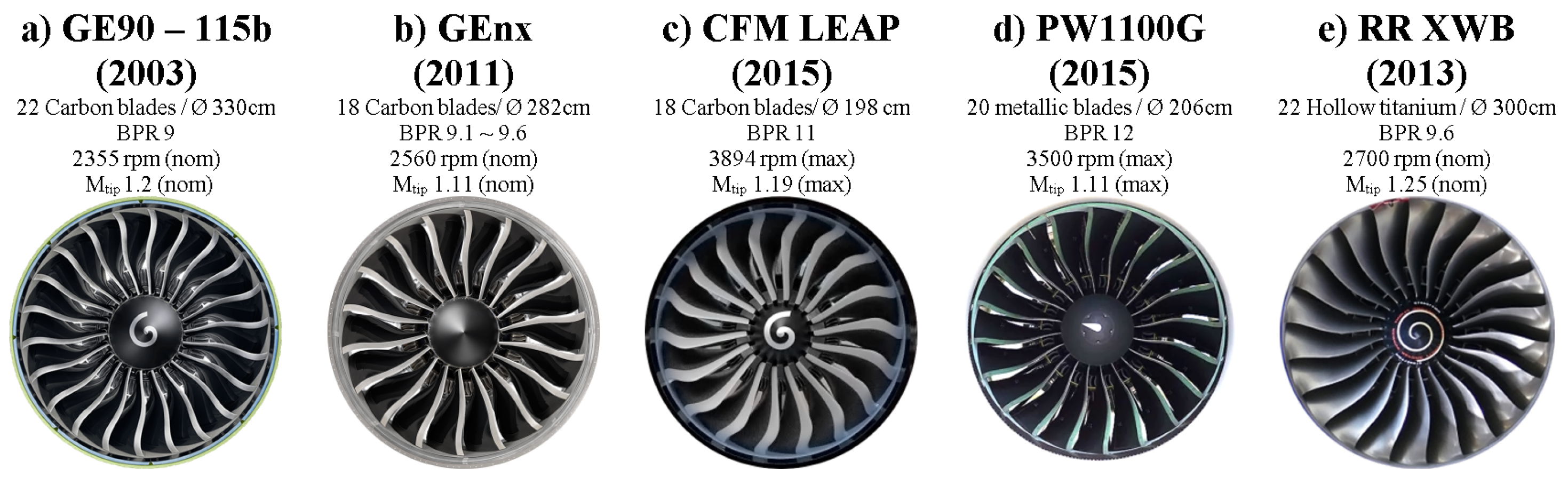
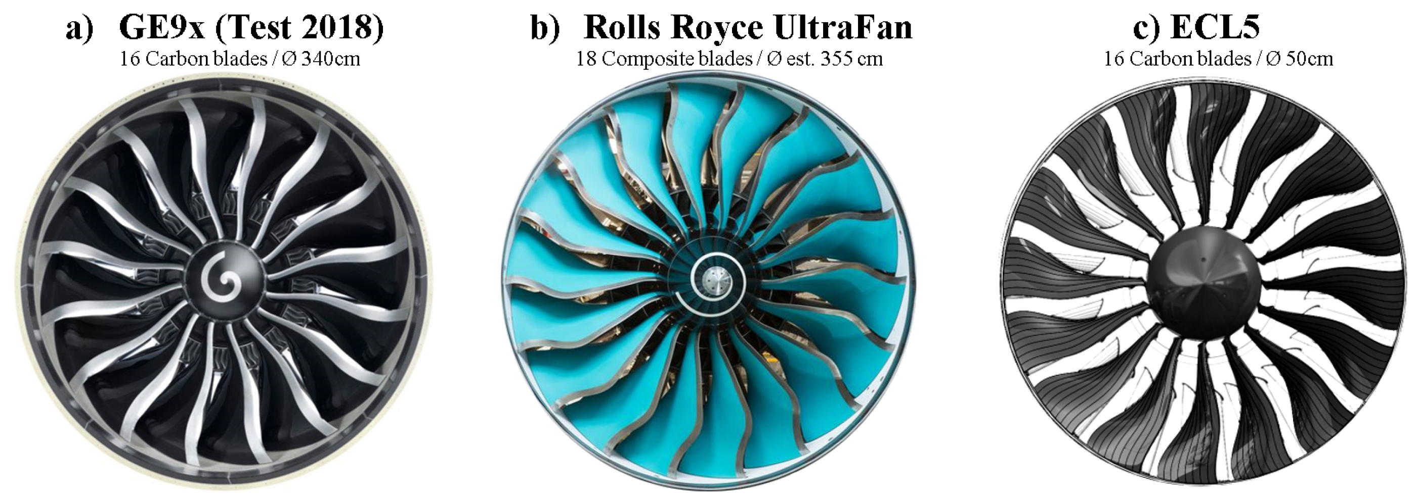
All the fan blades shown have significant 3D features, particularly forward sweep, which is known to be beneficial for aerodynamic performance but emphasizes aeroelastic sensitivity for torsional or chord-wise bending modes and particularly NSV. Recent research [14,15] has shown that the use of the anisotropic properties of composites in fans could help to improve both the mechanics and aerodynamics. Composites also present the potential to control flutter by modification of the eigenmodes [16].
In order to enable further technological advancements in this direction, extensive research is necessary to identify and characterize the relevant instability mechanisms for the novel type of low-speed fan. In particular, the complex flow structure at part load and part speed is challenging for state-of-the-art numerical approaches and requires experimental benchmark data on representative geometries.
To address these research objectives, an extensive research program with collaboration between Ecole Centrale de Lyon and the Von Karman Institute for Fluid Dynamics has been initiated. A fan module, ECL5, fabricated from composite material, has been developed as an open test case. It will be investigated, with a focus on non-synchronous coupling mechanisms between aerodynamics, acoustics and structure dynamics, within the European Clean Sky 2 project CATANA (Composite Aeroelastics and Aeroacoustics, catana.ec-lyon.fr). The fan stage was designed at Ecole Centrale de Lyon and was intended to be representative of near-future composite low-speed fans in terms of the following:
1.
General aerodynamic design parameters (Mach number, blade loading, solidity, aspect ratio, hub-to-tip ratio, mass flow density, etc.)
2.
Aerodynamic flow structure, due to its influence on instability mechanisms (shock patterns, radial flow migration, secondary flow, separations, etc.)
From the current point of view, the most promising research configuration is a UHBR low-speed fan stage with high subsonic design speed, designed to be installed in midrange jets (such as Airbus A320neo). Hence, the open-test-case ECL5 that will be introduced in the following was developed from an extrapolation of industrial concepts for current low-speed designs. In Figure 2, (image sources (accessed on 20 September 2021): (a) https://www.additivemanufacturing.media/mission-critical/; (b) https://www.air-cosmos.com/article/rolls-royce-tests-ultrafan-low-pressure-system-592, image flipped), the final design is shown in comparison to the recently certified GE9x and the Rolls Royce UltraFan technology demonstrator.
In the following, the final design and the composite structure of the fan are presented. Details are given on the modelling strategies used to simulate the different physics: stationary flow simulations (RANS), mechanical simulations (FEM) and time-linearized simulations (LRANS). Finally, the aerodynamic behaviour and structural dynamics of the fan are deduced, and its aeroelastic stability is assessed.

2. ECL5 Description

2.1. Design Approach

Based on an initial design [17], the final design was obtained with the use of a modularly coupled design chain, including a parametric blade geometry generator, automatic meshing, a steady RANS solver and structural FEM simulations. The fan geometry fulfils the following design objectives:
  • A blade number of 16 (lowest blade count in technology demonstrators as shown above).
  • A fan diameter of 508 mm to enable integration into the test facility PHARE-2, with blade root compatible with the existing disk from Project ENOVAL [18].
  • Aerodynamic design point (fan only) at peak efficiency with a pressure ratio of 1.36, a mass flow density maximum of 200 kg/s/m 2 and a rotation speed of 11,000 rpm.
  • Near-sonic relative tip Mach number at the design point.
  • Isentropic efficiency (fan only) exceeding 94 % at the design point.
  • At peak pressure at the design speed, no flow separation at the trailing edge.
  • Peak efficiency at 105 % and speed not lower than 92 % (transonic speedline).
  • Nominal tip clearance of ∼1 mm ( 1.1 % tip chord) to ensure stall inception and surge experiments without casing contact. Future experiments are planned with further reduced tip clearance.
  • Fan to be fabricated without integration of a metallic leading edge.
For the OGV, no specific design criteria were set except for a minimization of the (numerical) corner separation under highly loaded conditions and minimum losses at the design point. The blade number was fixed at 32 in the optimization process and reduced to 31 for the final design, to avoid the establishment of planar acoustic interactions.
Stage inlet and outlet geometry is similar to previous installations [18]. The same applies to the casing geometry in the fan section. The OGV is located far downstream of the fan to minimize interactions, as the focus of the research project was on the fan. As the facility comprises only a single flow channel, engine-representative OGV aerodynamics are not intended; only axial stage outflow and homogeneous radial conditions are required to ensure detailed performance analysis and to enable future research projects with a fundamental background in noise generation.
The development process is described in detail in Pagès [19]. The hubline, from nosecone to OGV outlet, was open for optimization. A section of the design is presented in Figure 3. Figure 4 shows the blade profiles at different span heights, clearly emphasizing the transonic blade design at the fan tip and the wide chord geometry around midspan. At the hub, the relative tangential velocity and the rotational speed have the same direction at the trailing edge, which is necessary in order to meet the design criteria laid out above but creates a challenging flow field with high swirl velocities upstream of the OGV.
The tip clearances for various rotation speeds are presented in Table 1:

2.2. Fan Composite Structure

The blade is exclusively made of unidirectional carbon fibres and epoxy composite plies stacked into a laminate with intentional ply orientations. A ply is considered to be made of orthotropic material. The three material orthotropy directions are defined locally as follows: direction 1 is the orientation of the carbon fibres, direction 2 is orthogonal to direction 1 within the ply and direction 3 is orthogonal to the ply. The constitutive law of the composite material is described classically by nine constants, as listed in Table 2 (indicated by the composite manufacturer).
The maximum thickness of the blade (at the root) is 13.3 m m . The thickness of a ply is 0.15 m m , so the maximum number of plies is 88. The internal structure is symmetric with respect to the laminate midplane, to minimize the coupling of in-plane and out-of-plane movements. Each point of the midplane is associated with a number of plies defined by the local blade thickness. Plies are ranked by their size from largest to smallest (see Figure 5).
For the design process, plies were divided into two families. The 18 largest plies are called blade plies and the others—the smallest—are called core plies. To reduce the number of degrees of freedom for the design, the orientation of core plies was set, considering half a blade, in the sequence ( 0 / 90 ) 6 ( 0 / 90 / 0 ) 4 ( 0 / 0 ) s , with 0 defined as the radial direction. Their influence on global elastic properties is minor; they mainly contribute to thickness adjustment. Thus the total number of fibre orientations to be defined was set to 18. These orientations are listed in Table 3. The orientation of a ply is defined as illustrated in Figure 5b. The orientation is imposed on a chosen point at the root of the blade. Local orientation along the blade is determined by the draping of the surface [20].
The manufacturing process consisted of three steps. First, each pre-impregnated ply was cut to the predefined shape. Secondly, the plies were stacked into two half-molds. Then, both molds were pressed together before heating to start the epoxy polymerisation process.
The plies were stacked in a particular way to improve the manufacturing process and the final resistance to delamination. This was an alternation of blade plies and core plies, as illustrated in Figure 5a. One particular feature is that Ply 1 (the largest, Figure 5b) was placed at the external surface of the blade. Thus, the external surface is composed of only one ply and has a very low surface roughness with no sharp step.

3. Modelling Strategies

3.1. Aerodynamics

For the aerodynamic simulations, a structured mesh was created using AutoGrid (https://www.numeca.com, accessed on 20 September 2021). A single passage of the fan domain contains 3.5 million cells, with 141 layers in the radial direction, and 41 layers are used in the tip gap. The OGV domain contains 1.7 million cells, with 101 layers in the radial direction and no tip gap. The fan meshing is illustrated in Figure 6.
Stationary flow simulations were conducted using the RANS solver FineTurbo (https://www.numeca.com, accessed on 20 September 2021). The wall resolution of this mesh is below y + = 1 for design conditions. A k ω SST turbulence model was used for the simulations presented in the following. This methodology was validated in a study on a comparable low-speed fan for the operating range between choke and peak pressure [18]. A study on mesh convergence is presented in [19].

3.2. Mechanics

The FEM solver Ansys was used for the mechanical simulations (https://www.ansys.com/products/structures/ansys-mechanical, accessed on 20 September 2021). The simulation domain and boundary conditions are presented in Figure 7a. A cyclic symmetry condition is imposed on the faces of the disk sector (in purple) since the fan should be tuned and all blades should be identical. The shaft of the test facility is not modelled. To represent the contact between the disk and the shaft, the disk is clamped in the blue area and the axial displacement is set to zero in the green area. The aerodynamic pressure field is imposed on the red surface. Static simulations include large deflection.
The blade composite laminate was modelled by a hexaedric 3D mesh (Ansys ACP (https://www.ansys.com/products/structures/composite-materials, accessed on 20 September 2021)) and a dedicated procedure to model the ply alternation. To reduce the mesh size, a stack of plies was modelled with an equivalent element. Each half-thickness was modelled by an equivalent element (see Figure 7b) with orthotropic properties, homogenized by classical laminate theory [21].

3.3. Aeroelasticity

3.3.1. Energy Method

The aeroelastic stability was investigated with the energy method [22]. This approach is based on the assumption that flow fluctuations do not affect the structural dynamics and are linear with respect to the vibration amplitude. It consists of two steps. First, eigenmodes and natural frequencies are determined. Secondly, an unsteady flow simulation is performed to compute the harmonic variations of the flow caused by the vibration. Aeroelastic stability is determined by the energy transfer from the structure to the flow. It is assessed by the pressure-force work W per vibration cycle. For positive work ( W > 0 ), the blade releases energy to the fluid, so that vibrations are damped. For negative work ( W < 0 ), energy is transferred from the fluid into the structure, thus exciting the blade vibration and leading to aeroelastic instability. In agreement with industrial convention, the aerodynamic damping value is defined in the following as:
ζ = W 4 π E k = W 2 π M 0 ω 0 2
where E k is the modal kinetic energy of the travelling wave, M 0 is the modal mass and ω 0 is the vibration angular frequency.

3.3.2. Time-Linearized Simulations

An isolated fan was considered for the stability study, according to common practice for fan flutter studies based on self-excitation [3,23,24]. The OGV is at a distance of one chord downstream of the fan, so its potential influence is significantly reduced.
To assess the stability of the fan, a time-linearized method (LRANS) was used. Based on the assumption of small harmonic perturbations, the coordinates of the grid vertices, as well as the flow solution, can be decomposed into a steady part and a time-dependent harmonic perturbation. These two parts were simulated separately.
The steady flow necessary for LRANS simulations was obtained with the compressible RANS solver elsA (http://elsa.onera.fr/, accessed on 20 September 2021). The solver relies on a cell-centred finite volume method on multi-block structured grids. Convective fluxes are obtained using the Jameson scheme with artificial dissipation. The turbulence was modelled by a k ω Kok model with vorticity-based computation of turbulent kinetic energy production. A single passage of the fan domain was reduced to 2.3 million cells, with 101 layers in the radial direction and with 21 layers used in the tip gap. The wall resolution remains below y + = 1 . A comparison of the steady-state results with those obtained with FineTurbo was carried out and showed few disparities, resulting in differences lower than 0.3% in the total pressure ratio and 0.3% in the isentropic efficiency for the studied operating points.
The unsteady flow was obtained with the solver Turb’Lin [25]. The solution was obtained in the frequency domain. This vertex-centred LRANS solver has been validated for transonic separated flows [25,26]. The turbulence model was linearized (see [27] for a comparison with results for a frozen turbulence assumption). Upstream and downstream of the fan, the mesh was extended by numerous fan diameters with strongly reduced axial resolution, to attenuate acoustic reflections.

4. Results

4.1. Aerodynamic Characteristics

The stage characteristics of steady RANS calculations throttled via static pressure at the stage outlet are presented in Figure 8. It can be seen that the overall peak efficiency is well located at the 100 % speedline, at a point where the total pressure characteristic is almost flat. For high speedlines above 100 % of the design speed, choke occurs in the fan; otherwise, it occurs in the OGV. Towards low mass flows, the speedlines are rolled over and limited by numerical convergence. This is comparable to the case presented by Rodrigues et al. [18], showing that through the application of a choked nozzle far downstream, the numerical stability limit can be further extended while still not reaching the stability limit of the experiment. Under highly throttled conditions, the performances in the experiments are expected to significantly deviate from the numerical results. In this paper, five operating points representative of the different flow topologies and limits are presented. OP-A is the design point, OP-B is the maximum pressure ratio and OP-C presents a choked flow at 100 % speed. OP-D and OP-E are operating points near the maximum pressure ratio at 80 % speed.
A detail of the 100 % speedline is given in Figure 9, showing the pressure and efficiency characteristics as well as the radial profiles at the rotor exit (aerodynamic simulations were for a constant 1.5 mm tip clearance, and the fabricated fan had tip clearance according to Table 1). In a wide range between OP-B and OP-C (representing 19 % of the design mass flow, depicted in cyan in Figure 9), the fan produces a flat efficiency characteristic above 88 % . The evolution between the low-throttled operating point OP-C and the higher-throttled conditions shows that the fan is barely affected between the hub and midspan. The maximum pressure ratio is observed near the midspan, and throttling increases the loading of the blade tip. At design point OP-A, the efficiency profile is almost constant between 20 % and 80 % span. The influence of the tip leakage flow is observed between 85 % and 100 % span for all conditions shown.
In Figure 10, the flow structure is presented in more detail for design point OP-A. The isentropic Mach number distribution on the suction side shows the shock structure from midspan and emphasizes the reduced loading at the blade tip. Surface streamlines are homogeneous, without indications for flow separations but with moderate radial migration towards the trailing edge. The blade-to-blade view of the relative Mach number and radial velocity at 95% span indicates low blockage in the tip region and a clearly depicted tip leakage vortex that interacts mildly with the shock.
This situation changes at the maximum pressure condition OP-B, where the pre-shock Mach number strongly increases, and the surface streamlines show signs of boundary-layer separation between 70% span and the casing. In addition, radial migration is accentuated, leading to low relative Mach numbers below 0.2 at the trailing edge at lower channel heights. The blade-to-blade view depicts a strong blockage zone enclosed by the emphasized tip clearance flow. Here, a stronger interaction with the shock is indicated.
The same illustration is given for the maximum pressure point at the 80% speedline, OP-D. Here, the flow is mostly subsonic. The supersonic zone (without shock) in the isentropic Mach number distribution is due to the circumvention of the leading edge. Surface streamlines indicate significant local backflow at the leading edge for higher channel heights. The blockage region at the fan tip is more severe than at the design speed, with a widely inclined zone of negative radial velocity. Radial flow migration is highly accentuated at this condition, particularly close to the casing. However, due to the low relative velocity, the amplitude of the radial velocity close to the casing is lower than for the higher speedline.

4.2. Mechanics

4.2.1. Static Mechanics

Hot shapes of the fan blade were determined for each speedline along the working line. Due to the use of the anisotropic properties of the composite, the maximal blade displacement was 1.15 m m at maximal speed, corresponding to 1.0 % of the chord. This is comparable to the optimization presented by Schmid et al. [15]. The maximum static stress in the fibre direction does not exceed 17 % of the elastic limit. The static stress is therefore low compared to the elastic limit, which allows a sufficiently high level of dynamic stress during the experimental campaign.

4.2.2. Mode Shapes

Regarding the synchronous excitation phenomena, intake distortions are the predominant sources. The potential effects of the OGV are negligible because of the axial distance from the fan of more than one chord. Experience on similar configurations shows that above the 6th engine order, forced response amplitudes are negligible [18,28]. At 105 % of nominal rotation speed, the frequency of the 6th engine order is 1155 Hz . Mode 3 and Mode 4 frequencies are around 900 Hz and 1500 Hz , respectively, at maximal rotation speed, so only the first three modes are considered in the following.
Modal data are presented only for positive nodal diameters, because they are identical for both co-rotative and contra-rotative modes. Modal frequencies are given in Figure 11a for each nodal diameter (ND). Frequency variations are less than 2%, except for low nodal diameters between modes of the same family. The Mode 1ND0 frequency is lowered by 9 % compared to the other NDs. The Mode 2ND1 and Mode 3ND1 frequencies are also reduced by 12 % and 14 % , respectively. To assess the mode shape variations between nodal diameters, the modal assurance criterion (MAC) was used [29]. For each mode, the mode shape was compared to its ND8 counterpart. The MAC value is equal to 1 if the mode shapes are identical and 0 if they are inconsistent. The MAC values are represented in Figure 11b. Except for ND1, the three modes are superimposed at 1. Modes 2ND1 and 3ND1 are very different from the other NDs due to the high disk contribution. The Mode 1ND0 mode shape is comparable, although its frequency is slightly different. These significant variations between nodal diameters must be taken into account in aeroelastic studies. Furthermore, the accuracy of the prediction can be affected by the support stiffness and gyroscopic effects. Thus, the choice to model the disk without the shaft could have an important impact on this nodal diameter (ND1) and must be addressed in further studies.
The mode shapes at ND2 are shown in Figure 12. ND2 is representative of all nodal diameters except ND1. Mode 1 is a bending mode with a very low torsional component. The displacement is almost purely circumferential without an axial component. Mode 2 shows a pronounced torsional component at the blade tip, which is known to be critical for fluid–structure interactions [8,30]. Mode 3 represents a torsional mode with the torsional centre positioned at half-chord at midspan and at the leading edge at the tip.
Mode shapes at ND1 are shown in Figure 13. As identified in Figure 11b, Mode 2ND1 and Mode 3ND1 are very different from the other equivalent NDs. In particular, the mode shape of 3ND1 is closer to Mode 2 than to Mode 3.

4.2.3. Campbell Diagram

The Campbell diagram obtained for the fan is presented in Figure 14. The crossings of the different modes with EO lines are highlighted. Modal frequencies were adjusted during the design process—as a result of the carbon fibre orientations—to prevent crossings above 100% speed. These are sufficiently distributed in frequency to enable safe tests, i.e., without fatigue caused by resonance, at low part-speed (∼50%), high part-speed (∼80%) and full speed (100% and above). Experience shows that the predicted frequencies are slightly higher than those of manufactured blades. Fans produced by the same manufacturer show that the frequency predictions are nearly 5% higher for torsional modes [18,28]. Moreover, in previous experimental campaigns, crossing with engine orders higher than 3 did not prevented speedline exploration. Hence, the 80% speedline could be safely investigated, despite the crossing of Mode 3.

4.3. Overall Stability Analysis

4.3.1. Strategy

To be representative of industrial configurations and to enable comprehensive experimental campaigns, it is necessary that the fan presents stable operating conditions at every planned experimental rotation speed. An exhaustive review would test every nodal diameter of every mode at each rotation speed. Even with the LRANS method, this exceeds the scope of a design study. The systematic stability analysis is limited to four operating points. The design point OP-A serves as a reference and must be stable in any case. OP-B, OP-C and OP-D are representative of the different flow limits (see Figure 8).
Flutter events detected on modern fans mostly involve the first bending mode at low nodal diameter [3,23,24]. However, it was shown by Stapelfeldt and Brandstetter [8] that torsional mode shapes could lead to aeroelastic instability for a convective mechanism, denoted as non-synchronous vibration. Thus, all three modes were investigated. Table 4 gives the reduced tip frequencies (see Equation (2)) based on the chord and the upstream relative velocity at both considered speeds.
k r = f r c U t i p
To reduce the number of aeroelastic configurations simulated, only even numbers of nodal diameters were simulated in a first step. The nodal diameters ± 1 were added because their aeroelastic behaviour cannot be deduced from other nodal diameters, due to their mode shape (see Figure 12 and Figure 13). Odd nodal diameters were simulated if discontinuities in aerodynamic damping curves were observed.

4.3.2. Aerodynamic Damping

Figure 15 and Figure 16 show the aerodynamic damping ratio ζ as function of the nodal diameter at operating points OP-A to OP-D. The minimal values of each curve are shown in Table 5. At OP-A, the design point, the aerodamping is always positive and the minimal value reached is 1.38 % . Mode 1 aerodamping variations as function of nodal diameter are smooth for every operating point. The smallest value occurs between ND0 and ND2, and it exceeds 5% for high NDs. For every operating point studied, Mode 1 is globally more stable than Mode 2 or Mode 3, especially at high NDs. Aerodamping curves for Mode 2 and Mode 3 are more erratic, and minimal values are reached for various NDs. Only one point was found to be unstable: Mode 2ND5 at OP-D. Among all other simulated configurations, the aerodamping is always higher than 0.69 % .

4.3.3. Influence of Mode Frequency and Mode Shapes on Damping

Abrupt changes are observed in the damping curves. Among the possible reasons could be the change of mode shape and frequency for low nodal diameters (see Figure 11). This dependency is quantified at OP-A in Figure 15a. The aerodynamic damping was computed with the same frequency and mode shape as ND8 (uniform modes), which is similar to ND2, as shown Figure 12. It is compared to the aerodynamic damping obtained with modes from FEM (real modes). The resulting curves with uniform modes are smoother. The aerodamping is mainly impacted at Mode 2 ND ± 1 and Mode 3 ND ± 1 , whose modal shapes and frequencies are very different from other NDs. Mode 1ND0 has a shift in frequency of 9 % ; however, the impact on the stability behaviour is marginal. The erratic changes observed between nodal diameters 2 and 2 are mostly due to mode shape variations.

4.4. Instability Analysis

Upstream and downstream acoustic conditions can produce discontinuities in the stability behaviour of the blades [31]. At the operating points studied, numerous switches between cut-on and cut-off conditions can be observed, but only three discontinuities were identified related to acoustic behaviour that could lead to instability: nolistsep
  • For Mode 2ND-3 at OP-A, the stability curve is flat at each side of the discontinuity and the fan remains stable (see Figure 15a).
  • For Mode 3ND-3 at OP-C, the stability reaches a minimum but the fan remains stable (see Figure 16a).
  • For Mode 2ND5 at OP-D, the fan is predicted to be unstable (see Figure 16b). The stability behaviour for ND4 to ND6 is investigated in the following.

4.4.1. Aeroelastic Instability of Mode 2 at OP-D

For Mode 2ND5 at OP-D, the fan is predicted to be unstable and the aerodamping reaches a negative minimum at ζ = 5.6 % . The local work at the surface of the blade, normalized according to the global work by U = 4 π E k (see Equation (1)), is plotted (Figure 17) for ND4 to ND6. The local work is mostly located at the tip of the blade due to the mode shape (see Figure 12b). Corresponding flow fluctuations at ND5 are more than one order of magnitude higher than for adjacent nodal diameters. For example, if the displacement is arbitrarily set to 1.0 % of the chord at the tip, the maximal pressure fluctuations are 65 % of the inlet static pressure. At ND5, fluctuations cannot be analysed quantitatively because this lies outside the hypothesis of small perturbations on which the linearized method is based.
At ND4 and ND6, the hypothesis of small perturbations remains valid, and the work distribution can be analysed. Figure 17 shows that both the suction side and the pressure side are equivalently involved in the overall stability of the blade. The local work patterns between ND4 and ND6 on the pressure side are similar but of opposite sign. On the suction side, the patterns are different. At ND4, the work is negative then positive near the leading edge, with high values, whereas the work is mildly positive at ND6 over a large area. This important change in behaviour between these nodal diameters indicates resonance, which is reached near ND5. The damping value obtained at ND5 is questionable due to resonance. However, it still shows that instability could be expected under these operating conditions, which must be investigated with caution during experiments.

4.4.2. Acoustic Propagation Conditions

The propagation conditions [32] of Mode 2 at OP-D are presented in Figure 18. This figure provides an understanding of the acoustics in the duct. An acoustic pressure wave generated by a vibrating fan can propagate axially if the frequency in the steady frame of reference f s is higher than a frequency f c u t , called the cut-off frequency, where f s is determined by Equation (3).
f s = | f r + Ω ND |
where f r is the frequency in the rotating frame of reference (i.e., the modal frequency). With the assumptions of uniform flow in the radial direction, rigid-body flow and a hard-walled duct, the acoustic cut-off frequency for a subsonic axial flow can be estimated according to Hellmich and Seume [32] as:
f c u t = k r a 2 π 1 M x 2 ± M θ
where M x and M θ are the axial and circumferential Mach number, a is the sound speed and k r is the radial modal wave number calculated from Bessel functions. M x and M θ are determined by the mean value far upstream and downstream of the blade. The propagation conditions are shown in Figure 18 and were verified in the linearized simulation results. Upstream, acoustic waves propagate at ND0 to ND6. Downstream, acoustic waves propagate at ND4 but not at ND5 or ND6. In the opposite direction, propagation occurs at neither ND5 nor ND6. Vibration patterns that fulfil this condition of being cut on only in one axial direction are known to be critical for aeroelastic stability [6,33]. The discontinuity observed in the aerodamping curve (Figure 19) for OP-D seems to coincide with the change in the acoustic propagation conditions shown in Figure 18.

4.4.3. Influence of Operating Point

The aeroelastic stability is compared between OP-D and OP-E for Modes 2ND4 to 2ND6. At OP-E, the mass flow is 3.8 % higher than at OP-D, and the leading-edge separation size is reduced to 25 % of the chord. The acoustic cut-off frequencies at OP-E are not shown in Figure 18, because the differences from OP-D (less than the symbol size) are not significant compared to the model accuracy. It was verified in simulations that the acoustic propagation conditions upstream and downstream for ND4 to ND6 were the same for both operating points. The normalized local work distributions are presented in Figure 20. In contrast to OP-D (see Figure 17), the results show very little influence of the nodal diameter at this operating point and only stabilizing aerodynamic damping higher than 2.0 % (see Figure 19). On the suction side, the work repartition resembles ND4 at OP-D but with lower amplitude. Unlike the results at OP-D, the work on the pressure side is one order of magnitude lower than on the suction side. Here, the stability of the blade is driven by the suction side. The shift of 3.8 % in the mass flow leads to a stable system and suppresses the strong influence of nodal diameter on fan stability. Thus, even if the acoustic conditions are similar, the fan remains stable closer to the operating line. Based on the presented study, it is not clear whether the acoustic conditions are the dominant driver for instability or whether a convective mechanism as described by Stapelfeldt and Brandstetter [8] leads to aeroelastic lock-in (non-synchronous vibrations). The latter case is not unlikely, as the ND5 pattern can be in resonance with a backward-travelling aerodynamic disturbance of wave-number 11 (aliased on a 16-blade rotor). This disturbance would propagate with a speed of ≈60% of the fan speed in the absolute frame of reference, which is well within the range of reported convective disturbances [18]. However, it has not been investigated before using time-linearized methods. Nevertheless, the detected instability at OP-D does not prevent experimental exploitation of the speedline, as it occurs only close to the stall limit and in cases where convective lock-in limit-cycle oscillations are expected.

5. Conclusions

A fan representative of modern UHBR fans was designed and presented as an open test case. The fan blades were made of unidirectional carbon fibres and epoxy composite plies. To enable an analysis of the dynamic behaviour, the structural properties, manufacturing process and ply orientations were presented.
The second mode of the fan had a significant torsional component at the blade tip which makes it likely to be critical for fluid–structure interactions. Modes of the same family vary significantly at low nodal diameters. The impact of this disparity was quantified in aeroelastic studies. The fan stability was systematically investigated over representative operating points using a time-linearized method. At nominal speed, no aeroelastic instabilities were predicted. Thus, it was possible to investigate highly loaded operating conditions. At part-speed, a potential instability was identified under throttled conditions, and this will be investigated in more detail in future work. It was shown that the instability area remained localized far from the operating line, and this will be the focus of the planned experimental campaign which is expected to start in mid-2022.

Author Contributions

Conceptualization: V.P., P.D., S.A., L.B., P.F., X.O. and C.B.; methodology: V.P., P.D., S.A., L.B., P.F., X.O. and C.B.; investigation: V.P., P.D., S.A., L.B., P.F., X.O. and C.B.; writing—original draft preparation: V.P. and C.B.; writing—review: P.D., S.A., L.B., P.F. and X.O.; review and editing: V.P. and C.B.; visualization: V.P. and C.B.; supervision: P.D., S.A., L.B., P.F., X.O. and C.B.; project administration/funding acquisition: S.A., X.O. and C.B. All authors have read and agreed to the published version of the manuscript.

Funding

This project received funding from the Clean Sky 2 Joint Undertaking (JU) under grant agreement No. 864719. The JU receives support from the European Union’s Horizon 2020 research and innovation programme and the Clean Sky 2 JU members other than the Union. This publication reflects only the authors’ view, and the JU is not responsible for any use that may be made of the information it contains. The development of the open-test-case fan is supported by CIRT (Consortium Industrie-Recherche en Turbomachine).

Institutional Review Board Statement

Not applicable.

Informed Consent Statement

Not applicable.

Data Availability Statement

The geometry, experimental results and available simulations are accessible to European research institutes and international researchers upon negotiation. Registration at catana.ec-lyon.fr, accessed on 20 September 2021.

Acknowledgments

The authors are grateful for the continuous support of Safran Aircraft Engines, particularly the contribution of Laurent Jablonski during the design phase of the open test case.

Conflicts of Interest

The authors declare no conflict of interest.

Abbreviations

The following abbreviations are used in this manuscript:
EOEngine Order
FEMFinite Element Method
LRANSLinearized Reynolds-Averaged Navier–Stokes
NDNodal Diameter
NSVNon-Synchronous Vibration
OGVOutlet Guide Vanes (Stator)
OPOperating Point
RANSReynolds-Averaged Navier–Stokes
UHBRUltra-High Bypass Ratio

References

  1. Brandstetter, C.; Pagès, V.; Duquesne, P.; Ottavy, X.; Ferrand, P.; Aubert, S. UHBR Open-Test-Case Fan ECL5/CATANA, Part 1: Geometry And Aerodynamic Performance. In Proceedings of the European Turbomachinery Conference ETC14 2021, Paper No. 625, Gdansk, Poland, 12–16 April 2021; Available online: https://hal.archives-ouvertes.fr/hal-03257374 (accessed on 20 September 2021).
  2. Pagès, V.; Duquesne, P.; Ottavy, X.; Ferrand, P.; Aubert, S.; Blanc, L.; Brandstetter, C. UHBR Open-Test-Case Fan ECL5/CATANA, Part 2: Mechanical And Aeroelastic Stability. In Proceedings of the European Turbomachinery Conference ETC14 2021, Paper No. 626, Gdansk, Poland, 12–16 April 2021; Available online: https://hal.archives-ouvertes.fr/hal-03257377 (accessed on 20 September 2021).
  3. Vahdati, M.; Cumpsty, N. Aeroelastic Instability in Transonic Fans. J. Eng. Gas Turbines Power 2015, 138, 022604. [Google Scholar] [CrossRef]
  4. Lee, B.H.K. Self-sustained shock oscillations on airfoils at transonic speeds. Prog. Aerosp. Sci. 2001, 37, 147–196. [Google Scholar] [CrossRef]
  5. Dodds, J.; Vahdati, M. Rotating Stall Observations in a High Speed Compressor—Part I: Experimental Study. J. Turbomach. 2015, 137, 051002. [Google Scholar] [CrossRef]
  6. Fiquet, A.L.; Vercoutter, A.; Buffaz, N.; Aubert, S.; Brandstetter, C. Acoustic resonance in an axial multistage compressor leading to non-synchronous blade vibration. In Proceedings of the ASME Turbo Expo 2020 & Turbomachinery Technical Conference and Exposition, Online, 21–25 September 2020; ASME: London, UK, 2020. [Google Scholar]
  7. Kielb, R.E.; Barter, J.W.; Thomas, J.P.; Hall, K.C. Blade Excitation by Aerodynamic Instabilities: A Compressor Blade Study. In Proceedings of the ASME Turbo Expo 2003, Collocated with the 2003 International Joint Power Generation Conference, Atlanta, GA, USA, 16–19 June 2003; American Society of Mechanical Engineers Digital Collection; American Society of Mechanical Engineers: New York, NY, USA, 2003; Volume 4, pp. 399–406. [Google Scholar] [CrossRef] [Green Version]
  8. Stapelfeldt, S.; Brandstetter, C. Non-synchronous vibration in axial compressors: Lock-in mechanism and semi-analytical model. J. Sound Vib. 2020, 488, 115649. [Google Scholar] [CrossRef]
  9. Lee, K.B.; Wilson, M.; Vahdati, M. Validation of a Numerical Model for Predicting Stalled Flows in a Low-Speed Fan—Part I: Modification of Spalart–Allmaras Turbulence Model. J. Turbomach. 2018, 140, 051008. [Google Scholar] [CrossRef]
  10. Peters, A.; Spakovszky, Z.S.; Lord, W.K.; Rose, B. Ultrashort Nacelles for Low Fan Pressure Ratio Propulsors. J. Turbomach. 2015, 137, 021001. [Google Scholar] [CrossRef] [Green Version]
  11. Wilson, M.J.; Imregun, M.; Sayma, A.I. The Effect of Stagger Variability in Gas Turbine Fan Assemblies. J. Turbomach. 2006, 129, 404–411. [Google Scholar] [CrossRef]
  12. Lu, Y.; Green, J.; Stapelfeldt, S.C.; Vahdati, M. Effect of Geometric Variability on Running Shape and Performance of a Transonic Fan. J. Turbomach. 2019, 141, 101012. [Google Scholar] [CrossRef]
  13. Zhai, Y.; Bladh, R.; Dyverfeldt, G. Aeroelastic Stability Assessment of an Industrial Compressor Blade Including Mistuning Effects. J. Turbomach. 2012, 134, 060903. [Google Scholar] [CrossRef]
  14. Goerke, D.; Le Denmat, A.L.; Schmidt, T.; Kocian, F.; Nicke, E. Aerodynamic and Mechanical Optimization of CF/PEEK Blades of a Counter Rotating Fan. In Proceedings of the ASME Turbo Expo 2012: Turbine Technical Conference and Exposition, Copenhagen, Denmark, 11–15 June 2012; ASME: Copenhagen, Denmark, 2012; Volume 7: Structures and Dynamics, Parts A and B, pp. 21–33. [Google Scholar] [CrossRef]
  15. Schmid, T.; Lengyel-Kampmann, T.; Schimdt, T.; Nicke, E. Optimization of a carbon fiber composite blade of a counter-rotating fan for aircraft engines. In Proceedings of the 13th European Conference on Turbomachinery Fluid Dynamics & Thermodynamics, Lausanne, Switzerland, 8–12 April 2019; European Turbomachinery Society: Lausanne, Switzerland, 2019. [Google Scholar]
  16. Reiber, C.; Blocher, M. Potential of aeroelastic tailoring to improve flutter stability of turbomachinery compressor blades. In Proceedings of the 12th European Conference on Turbomachinery Fluid Dynamics & Thermodynamics, Stockholm, Sweden, 3–7 April 2017; European Turbomachinery Society: Stockholm, Sweden, 2017. [Google Scholar] [CrossRef] [Green Version]
  17. Rendu, Q. Modélisation des Écoulements Transsoniques Décollés pour L’étude des Interactions Fluide-Structure. Ph.D. Thesis, Université de Lyon, Lyon, France, 2016. [Google Scholar]
  18. Rodrigues, M.; Soulat, L.; Paoletti, B.; Ottavy, X.; Brandstetter, C. Aerodynamic Investigation of a Composite Low-Speed Fan for UHBR Application. J. Turbomach. 2021, 143, 101004. [Google Scholar] [CrossRef]
  19. Pagès, V. Conception du Fan UHBR ECL5 pour une Analyse des Mécanismes D’interactions Multi-physiques à L’origine du Flottement. Ph.D. Thesis, Ecole Centrale de Lyon, Lyon, France, 2021. [Google Scholar]
  20. Wang, J.; Paton, R.; Page, J.R. The draping of woven fabric preforms and prepregs for production of polymer composite components. Compos. Part A Appl. Sci. Manuf. 1999, 30, 757–765. [Google Scholar] [CrossRef]
  21. Barbero, E.J. Finite Element Analysis of Composite Materials Using ANSYS®, 2nd ed.; CRC Press: Boca Raton, FL, USA, 2013. [Google Scholar]
  22. Carta, F.O. Coupled Blade-Disk-Shroud Flutter Instabilities in Turbojet Engine Rotors. J. Eng. Power 1967, 89, 419–426. [Google Scholar] [CrossRef]
  23. Sanders, A.J.; Hassan, K.K.; Rabe, D.C. Experimental and Numerical Study of Stall Flutter in a Transonic Low-Aspect Ratio Fan Blisk. J. Turbomach. 2004, 126, 166–174. [Google Scholar] [CrossRef]
  24. Aotsuka, M.; Murooka, T. Numerical Analysis of Fan Transonic Stall Flutter. In Proceedings of the ASME Turbo Expo 2014: Turbine Technical Conference and Exposition, Düsseldorf, Germany, 16–20 June 2014; ASME: Düsseldorf, Germany, 2014;B: Structures and Dynamics; Volume V07BT35A020; Volume 7. [Google Scholar] [CrossRef]
  25. Rendu, Q.; Philit, M.; Rozenberg, Y.; Labit, S.; Chassaing, J.C. Time-linearized and harmonic balance navier-stokes computations of a transonic flow over an oscillating bump. In Proceedings of the 14th International Symposium on Unsteady Aerodynamics, Aeroacoustics & Aeroelasticity of Turbomachines, Stockholm, Sweden, 8–11 September 2015; ISUAAAT: Stockholm, Sweden, 2015; p. 14. [Google Scholar]
  26. Philit, M.; Ferrand, P.; Labit, S.; Chassaing, J.C.; Aubert, S.; Fransson, T. Derivated Turbulence Model to Predict Harmonic Loads in Transonic Separated Flows over a Bump. In Proceedings of the 28th International Congress of the Aeroanautical Sciences, Brisbane, Australia, 23–28 September 2012; ICAS: Brisbane, Australia, 2012; p. 11. [Google Scholar]
  27. Duquesne, P.; Aubert, S.; Rendu, Q.; Ferrand, P. Effect of nodal diameter on the local blades vibration on the choke flutter instability in transonic UHBR fan. In Proceedings of the 15th International Symposium on Unsteady Aerodynamics, Aeroacoustics and Aeroelasticity of Turbomachines, Gothenburg, Sweden, 16–17 October 2018; p. 10. [Google Scholar]
  28. Brandstetter, C.; Paoletti, B.; Ottavy, X. Compressible Modal Instability Onset in an Aerodynamically Mistuned Transonic Fan. J. Turbomach. 2019, 141, 031004. [Google Scholar] [CrossRef]
  29. Allemang, R.J. The Modal Assurance Criterion—Twenty Years of Use and Abuse. J. Sound Vib. 2003, 37, 14–23. [Google Scholar]
  30. Duquesne, P.; Mahieux, B.; Aubert, S.; Ferrand, P. Sensitivity of the aerodynamics damping coefficient prediction to the turbulence modelling conjugated with the vibration mode shape. In Proceedings of the 13th European Conference on Turbomachinery Fluid Dynamics & Thermodynamics ETC13, Lausanne, Switzerland, 8–12 April 2019; European Turbomachinery Society: Lausanne, Switzerland, 2019; p. 12. [Google Scholar]
  31. Ferria, H.; Ferrand, P.; Pacull, F.; Aubert, S. Numerical investigation of flutter stability in subsonic space turbine blisk with emphasis on cut-on/cut-off modes and interblade phase angles. J. Therm. Sci. 2012, 21, 492–499. [Google Scholar] [CrossRef]
  32. Hellmich, B.; Seume, J.R. Causes of Acoustic Resonance in a High-Speed Axial Compressor. J. Turbomach. 2008, 130, 031003. [Google Scholar] [CrossRef]
  33. Atassi, H.M.; Fang, J.; Ferrand, P. Acoustic blockage effects in unsteady transonic nozzle and cascade flows. In Proceedings of the 33rd Aerospace Sciences Meeting and Exhibit, Reno, NV, USA, 9–12 January 1995; AIAA: Reno, NV, USA, 1995; Volume 95-0303, p. 9. [Google Scholar]
Figure 1. Selection of established modern (ultra)-high-bypass-ratio engines.
Ijtpp 07 00017 g001
Figure 2. Modern industrial low-speed composite fans and open-test-case ECL5/CATANA (CAD).
Ijtpp 07 00017 g002
Figure 3. Section of ECL5 fan stage.
Ijtpp 07 00017 g003
Figure 4. Fan profiles at different span heights.
Ijtpp 07 00017 g004
Figure 5. Plies of ECL5 fan (coloured in green): (a) ply alternation; (b) Ply 1—blade, wrap; (c) Ply 6—blade; (d) Ply 19—core.
Ijtpp 07 00017 g005
Figure 6. Views of structured mesh for aerodynamic simulations: (a) blade to blade; (b) meridional; (c) O-mesh around the leading edge and the matching tip-clearance mesh.
Ijtpp 07 00017 g006
Figure 7. Mechanical model: (a) boundary conditions; (b) blade thickness meshing.
Ijtpp 07 00017 g007
Figure 8. Stage compressor map with operating points of interest.
Ijtpp 07 00017 g008
Figure 9. Detail of flow conditions at different operating points at 100% speed.
Ijtpp 07 00017 g009
Figure 10. Detail of flow conditions at different operating points.
Ijtpp 07 00017 g010
Figure 11. Nodal diameter influence on modes at 100% speed: (a) frequency; (b) MAC in comparison with ND8.
Ijtpp 07 00017 g011
Figure 12. Normalized modal displacement amplitude at ND2: (a) Mode 1; (b) Mode 2; (c) Mode 3.
Ijtpp 07 00017 g012
Figure 13. Normalized modal displacement amplitude at ND1: (a) Mode 1; (b) Mode 2; (c) Mode 3.
Ijtpp 07 00017 g013
Figure 14. Campbell diagram at ND2.
Ijtpp 07 00017 g014
Figure 15. Aerodynamic damping as a function of nodal diameter: (left) OP-A; (right) OP-B.
Ijtpp 07 00017 g015
Figure 16. Aerodynamic damping as a function of nodal diameter: (left) OP-C; (right) OP-D.
Ijtpp 07 00017 g016
Figure 17. Local work at OP-D for Modes 2ND4 to 2ND6: (left three blades) suction side; (right three blades) pressure side.
Ijtpp 07 00017 g017
Figure 18. Mode 2 (red dots) acoustic conditions at OP-D and OP-E.
Ijtpp 07 00017 g018
Figure 19. Mode 2 aerodynamic damping at OP-D and OP-E.
Ijtpp 07 00017 g019
Figure 20. Local work at OP-E for Modes 2ND4 to 2ND6: (left three blades) suction side; (right three blades) pressure side.
Ijtpp 07 00017 g020
Table 1. Tip clearance as predicted by FEM model (tip chord = 90 m m ).
Rotation SpeedTip Clearance (mm)Tip Clearance (% Tip Chord)
( 100 % = 11,000 rpm)Leading EdgeTrailing EdgeLeading EdgeTrailing Edge
0 % 1.00 1.50 1.11 1.67
50 % 0.98 1.30 1.09 1.45
80 % 0.87 1.12 0.97 1.25
100 % 0.78 0.99 0.87 1.10
105 % 0.77 0.92 0.86 1.02
Table 2. Material properties.
ρ E 1 E 2 = E 3 G 23 G 12 = G 13 ν 23 ν 12 = ν 13
1560 kg/m3 123.0 GPa 9.3 GPa 5.0 GPa 4.5 GPa 0.3 0.26
Table 3. Blade ply orientations.
Ply Nr.123456789
Orientation 45 45 15 30 15 15 70 0 0
Ply Nr.101112131415161718
Orientation 15 0 0 60 60 0 0 60 60
Table 4. Reduced frequency on working line (ND8).
Speedline 80 % 100 %
Mode 1 0.09 0.08
Mode 2 0.22 0.19
Mode 3 0.30 0.24
Table 5. Minimum of aerodynamic damping. Unstable condition marked in red.
Operating PointMode 1Mode 2Mode 3
OP-A ( 100 % , 36.0 k g / s ) 1.50 % 1.38 % 2.64 %
OP-B ( 100 % , 32.0 k g / s ) 1.20 % 1.15 % 1.64 %
OP-C ( 100 % , 38.9 k g / s ) 1.47 % 1.28 % 0.69 %
OP-D ( 80 % , 26.0 k g / s ) 0.83 % 5.60 % 0.89 %
Publisher’s Note: MDPI stays neutral with regard to jurisdictional claims in published maps and institutional affiliations.

