1. Introduction
In attempts to decrease latency, and increase security and reliability, some new AI solutions are gradually being deployed and executed on the edge. Stoica et al. [
1] and Carcillo et al. [
2] discuss challenges related to the field of AI, and list both edge computing and security as important topics of research. The term
edge intelligence is often used to describe the confluence of the edge computing and AI fields [
3].
Moving AI solutions to the edge may be required for systems that operate in environments where access to high-speed internet connections is either limited or non-existent, and available bandwidth is too low for effective data transportation. For instance, on-boat computer systems that operate in remote locations such as international waters and Antarctica rely on satellite connection to communicate with on-land services outside their environment. The development of 5G networks may improve connectivity in the future, but global coverage is not likely due to its short range [
4].
Deploying an AI system on the edge comes with certain challenges, particularly for monitoring and surveillance systems that are concerned with privacy regulations and agreements. Systems deployed at physically remote edge locations may be prone to attacks from malicious actors in the environment, and the consequences of data leaks are more severe when sensitive and private data are being generated and stored. AI systems that deal with private data of users also need to satisfy the requirements of privacy-governing laws such as the General Data Protection Regulation (GDPR) [
5] and constitutional rights to privacy. This places restrictions on the monitoring and data-collection process, while also heightening requirements of confidentiality and resilience to hostile attacks.
This article presents Áika, a robust system for executing distributed AI applications on the edge. Áika is developed and evaluated in a scientific context as a concrete edge computing platform specially targeting support for real-time AI systems with special security and fault-tolerance properties. A key property of Áika is how it remains active and performs continuous analysis of data during various component failures. We investigate how to provide efficient data analytics in an unstable and non-trusted edge environment.
Our work on the Áika system is motivated by the need for highly automated continuous AI-based monitoring and privacy-preserving surveillance of fishing vessels at sea. Fish is considered one of the most important food sources in the world, and it is estimated that it currently makes up around 17% of the current production of edible protein on a global scale [
6]. At the same time, the fishing industry has fallen victim to crime in the form of illegal fishing and over-exploitation. According to the United Nations Office on Drugs and Crime, crimes in the fishery industry are typically organized and transnational in nature, and include money laundering, illegal fishing, document fraud, and drug trafficking [
7]. The system is developed and evaluated in the context of surveillance and monitoring off the shore of Norway for the purpose of enforcing sustainable resource management and fish harvesting in the Arctic.
This computing environment is assumed to be both unstable and untrusted. Systems operating in it have elevated risk of faults and intrusions compared to stationary or cloud-connected systems. Factors that contribute to this risk include low and unpredictable bandwidth, high latency, unstable connections, remote locations, and uncertain time frames between physical interaction with the components of the system, in addition to the potential threat of malicious actors. The challenging weather conditions in the Arctic that such fishing vessels operate in are also a concern. This increases the importance of designing a robust and secure system that not only is able to tolerate faults, but can also detect and monitor them.
The main contributions of the work presented in this paper encompass the design of the Áika system, which enables the expression and execution of distributed AI applications, by utilizing a set of reusable design patterns for structuring distributed computations on the edge. We show that AI solutions can be executed in untrusted edge environments through a graph computation model, through our fault-tolerant middleware system that can detect, recover from, and report abnormal behavior.
In the following sections, we will discuss the motivation and architecture of our proposed system, followed by experiments, related work, and discussions.
2. Background
The sustainability issues and economic challenges related to illegal fishing have caused several governments to propose surveillance systems to track the activities of workers [
8,
9,
10], which has been characterized as privacy infringing and mass surveillance by some of those working on fishing vessels [
11]. The Dutkat framework [
12] was designed to retain some of the sustainability benefits of these programs [
13] while preserving the privacy of fishing vessel crew.
Solutions for distributed video analysis have been presented in several works related to surveillance, traffic monitoring, and smart city applications [
14]. Some deploy lightweight edge sensors that encrypt data before transmission [
15], while others choose to perform object detection and privacy preservation directly at edge nodes [
16]. Reliance on connectivity to a cloud service is common for these monitoring platforms; it is sufficient to perform transformations to reduce bandwidth usage or ensure privacy at the edge before performing the most computationally intense tasks in a more centralized and connected environment. However, the domain of fishing monitoring comes with a greater challenge of connectivity, and the bandwidth available for offshore fishing vessels is not sufficient to provide a satisfactory real-time transfer of video data [
17]. This calls for a system specialized for this domain, which can be deployed on resourceful vessels that continuously move in and out of edge environments with low bandwidth, high latency, and unreliable connectivity.
Nodes are expected to move into areas where they are unreachable from mainland services, which heightens requirements of fault tolerance and fault detection. Áika aims to recover from faults quickly in order to resume any interrupted computation processes and restore the system state. Manual inspections of the system during runtime may be challenging, or prohibitively expensive, due to the remote locations of nodes. As such, detected faults must be logged and classified for evaluation of its severity and probability of resulting from interference of malicious actors, to aid in decision making regarding the need for manual intervention or inspection.
Loading AI models into memory can be time consuming, which might negatively affect the recovery time. The system should therefore support resilient schemes by redundancy where replicated components process the same data, simultaneously. If one component fails, other components should still be processing its data, ensuring that throughput remains stable despite failures. The system should support configuration of resilient algorithms such as triple-modular redundancy, if a user wants to apply them to the system.
The domain of maritime surveillance involves storage and processing of data from various sources, including video and sensor data. Two practical storage challenges arise from this use-case and environment: First, nodes are geographically distributed and will be hindered by latency and bandwidth during retrieval of remotely stored data. It cannot be assumed that every node has access to all relevant data at all times. Second, the physical location of nodes, and the information they store locally, can be subject to varying juridical requirements and agreements. It is assumed that input data can contain sensitive information that is prone to privacy agreements and legal regulations. A distributed computation pipeline in an unstable environment may require geographic replication and redundancy to remain operative. At the same time, a system processing sensitive data may depend on agreements and regulations that restrict data consumption and movement, based on the information contained in input streams, particularly those containing videos and images of humans.
There are several systems that provide data storage and processing facilities. Client-Edge-Server for Stateful Network Applications (CESSNA) is a protocol developed to achieve resilient networking on a stateful edge computing system [
18]. The protocol provides consistency guarantees for stateful network edge applications and allows offloading of computations from clients and servers. This leads to a reduction in response latency, backbone bandwidth, and computational requirements for the client.
FRAME is a fault-tolerant and real-time messaging system for edge computing [
19] based on a publish–subscribe architecture, with a duplicated broker to avoid having a single point of failure. FRAME leverages timing bounds to schedule message delivery and replication actions to meet needed levels of assurance. The timing bounds are thus able to capture relation between traffic/service parameters and loss-tolerance/latency requirements. The architecture is implemented on top of the TAO real-time event service [
20].
Norwegian Army Protocol (NAP) is a scheme for fault tolerance and recovery of itinerant computations [
21]. The runtime architecture resolves around having a landing pad thread and a failure detection thread within each process. The landing pad is responsible for maintaining a NAP state object that stores information about mobile agents hosting execution or serving a rear guard. The landing pad thread is responsible for informing the failure detection thread which landing pad needs to be monitored. NAP uses a linear broadcast strategy that refines the strategy implemented by Schneider et al. [
22].
Falcon Spy [
23] provides distributed failure detection and recovery using a network of spies in the application, operating system, virtual machine, and network switch layers on the system being monitored. The spies are deployed at the different layers to hinder disruption. The motivation behind Falcon Spy is to enable effective failure detection and improve the previous method (end-to-end timeouts).
Dryad is a general-purpose distributed execution engine developed by Microsoft, used to execute coarse-grained data-parallel applications [
24]. One of Dryad’s key features is to allow the user to construct an execution DAG through a custom graph description language. The Dryad runtime maps the graph onto physical resources. The graph vertices allow an arbitrary number of inputs and outputs, unlike MapReduce [
25], which only supports single inputs and outputs. A job manager contains the application-specific code used to construct the communication graph. It also schedules work across available physical resources, which are maintained by a name server.
Cogset [
26] is a high-performance engine that builds on the principles of MapReduce [
25], but uses static routing while preserving non-functional properties. Cogset provides a few fundamental mechanisms for reliable and distributed storage of data and parallel processing of statically partitioned data at its core.
The Staged Event-Driven Architecture (SEDA) [
27] simplifies the construction of well-conditioned and highly concurrent Internet services. SEDA applications are constructed as a network of stages. A stage is defined as an application component that consists of three sub-components: an event queue that handles incoming events, an event handler, and a thread pool.
3. System Overview
Áika is designed to execute multiple distributed AI pipelines in a Directed Acyclic Graph (DAG) computation format on edge clusters, supporting a large range of complex distributed analytics executing on edge devices. Because Áika is intended to run in potentially hostile edge environments, actors cannot be fully trusted to fatefully execute any specified protocol and access to high-speed Internet may be limited. Fault tolerance is necessary to ensure that the system does not fail at runtime. Limited Internet connections can also lead to data being generated at a higher rate than the connection can transport. The solution is to move the analytical process to the edge, which is where the data are generated by sensors.
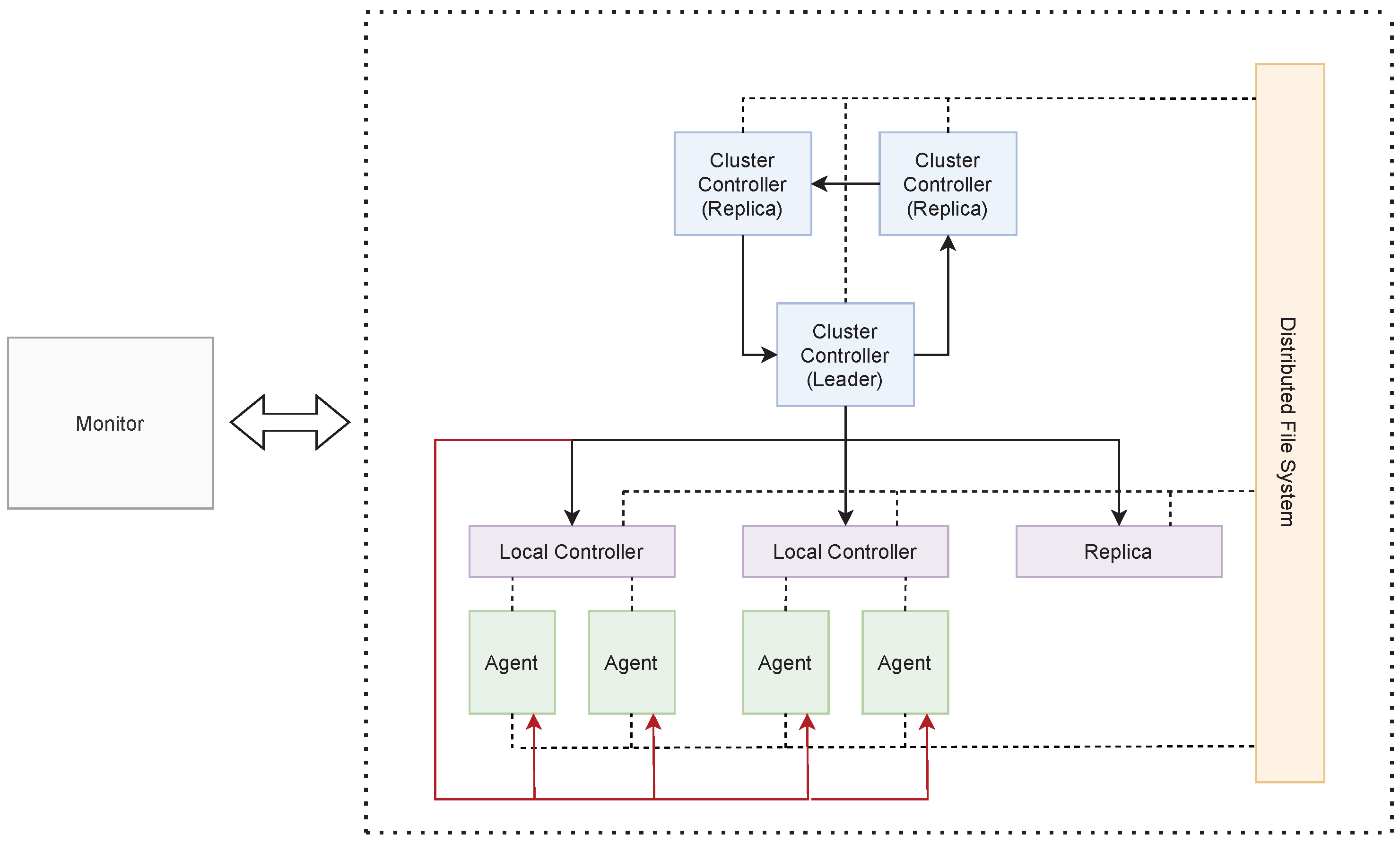
To support our requirements, we design Áika as a hierarchical system where a controller is responsible for monitoring the remaining part of the system and executing recovery when a component fails. The overall system is composed of multiple processes that communicate in a cluster. Each process has a specific role and it is not changed during runtime. The processes are as following:
Agent The agent is responsible for processing data. The agent can either fetch this data from the disk itself, or receive data from other agents.
Local Controller The local controller is responsible for monitoring the agents that reside on the same physical node as the local controller itself. Each physical device has at least one local controller running. A local controller without any agent to monitor is referred to as a replica. This type of local controller can be used for recovery if an entire physical node fails.
Cluster Controller The cluster controller is responsible for managing the entire cluster. It communicates with the local controllers to ensure that each physical node is running. If a physical node shuts down, the cluster controller is responsible for initiating recovery, either directly on the node where the failure occurred, or on a replica.
Monitor This is an additional process that is meant to be physically located on a trusted location, unlike the system itself. The monitor is responsible for communicating with the system to ensure that it is up and running. In the case of failure, the monitor may notify personnel or authorities about this.
3.1. System Components Structure
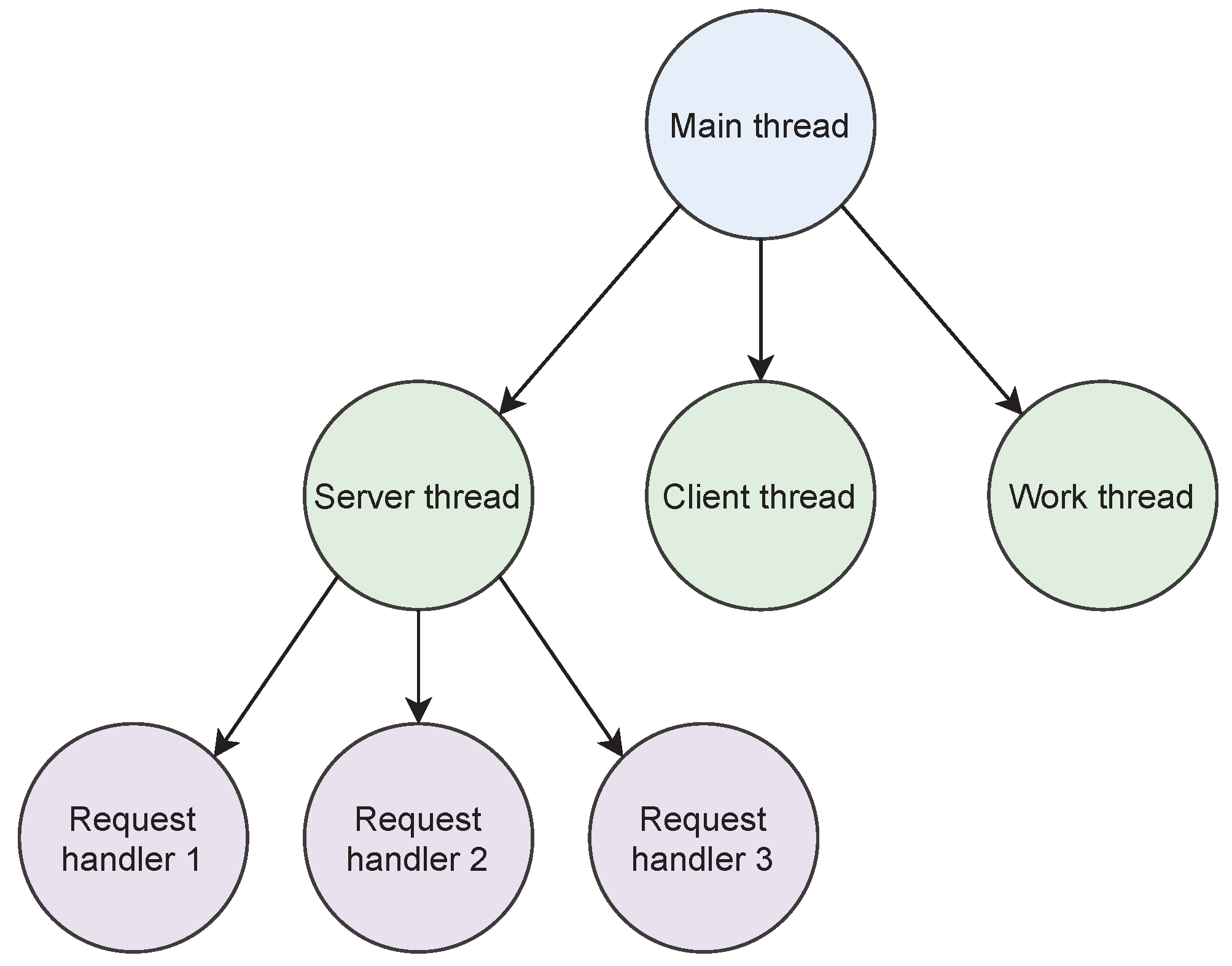
We design Áika using a hierarchical structure, as shown in
Figure 1. This structure also applies to each individual components. Each individual component is designed as a multi-threaded process. A main thread is responsible for initializing and monitoring child threads, where the child threads execute some type of behavior in the system. This can, for example, be to initialize a multi-threaded server, communicate with another component in the system through a client, or execute some form of custom work. This varies from component to component. If any of the child threads fail, they will be restarted by the main thread.
If a main thread shuts down, its child threads are also shut down and the entire process will fail. This approach ensures that servers are shut down if the main thread fails. This simplifies the recovery process, since no thread can be partially available and occupy resources after failure.
Figure 2 illustrates how processes can be organized into a hierarchy of threads.
3.2. Controllers
Áika implements a hierarchical multi-layered Controller/Agent design, where agents are managed by local controllers residing on each physical device. The local controllers are managed by a cluster controller that manages the remaining components in the system.
3.2.1. Local Controller
The local controller is responsible for monitoring the agents residing on the same physical nodes. It ensures that each agent is running and, in the case of crash failure, restarts the agent that crashed. It also logs the crash and the time of detection. In the event of a physical device crashing, a replica local controller will be responsible for restarting and recovering the local agents that crashed. This type of recovery process is initiated by a cluster controller.
3.2.2. Cluster Controller
The cluster controller is responsible for monitoring the entire cluster of computers that runs the system. The cluster controller has a Controller/Agent relationship with the local controller, where the local controller functions as the agent. Whenever a remote monitor attempts to connect to the cluster controller, it must provide a response to it to ensure the monitor that the system is running.
If a local controller fails, the cluster controller will attempt to recover it. The cluster controller initiates node failure recovery if it fails to recover the failed local controller. This means that the configuration of the failed local controller is forwarded to a replica local controller.
The cluster controller is duplicated to avoid complete system failure in the case where it crashes. The cluster controllers are organized into a chain (see
Figure 3) where each cluster controller responds to ping requests from their predecessor while pinging their successor. Each cluster controller has the full system configuration and therefore knows about all components. If the cluster controller in the chain fails completely and cannot be recovered, the predecessor will remove the cluster controller from its configuration and move to the next cluster controller in the chain.
If the main cluster controller fails, the duplicated controller that monitors the leader will attempt to recover it. If it fails the attempted recovery, it will instead become the new leader.
3.3. Agents
The agents are responsible for working with and processing the data, and they make up the core building blocks of the DAG computation model. The general task of each agent is thus to receive or fetch work (either from another agent or from file), then process data based on the work received before passing the results further ahead in the graph. Work items are transferred over client/server connections.
Figure 4 shows the general structure of the agents. A client or server thread is used to request or receive data from the previous agent. The thread continuously puts work items received on an input queue, which a work thread retrieves items from, before performing some type of work on the item. The result is put on an output queue. Another client or server thread is then used to forward the result to the next agent in the graph.
Preserving data integrity despite failure is achieved through the use of persistent queues, as they continuously write items to file as they are being inserted into the queue. In the case of failure, an agent will always be able to resume from the previous checkpoint upon recovery, as long as it is connected to the distributed file system. By writing the persistent queues to a file, a replica local controller will also be able to resume the work if the physical node shuts down, since it also will be connected to the same file system. A mechanism in the queue enables items to only be removed from file after work on the item has been completed and the result has been forwarded to the next queue. This mechanism is used both during work and during communication between agents to ensure that items are not lost.
The agents constitute the building blocks for a DAG, which is configured by the user. The DAG can be configured to be complex and, for instance, consist of nodes that receive data from multiple sources, or pass data forward to multiple sources. A set of base agents has therefore been created, which uses different combinations of client and server threads at each end. Each agent has particular use cases where they are useful. Note that the figures of each individual agent has abstracted the persistent queues between client and work away for simplicity.
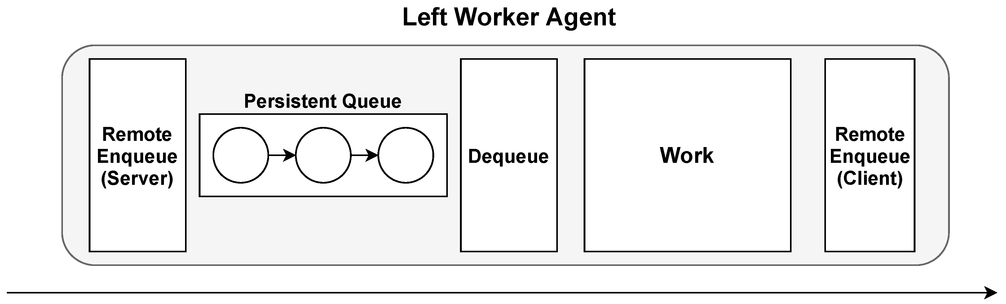
3.3.1. Left Worker Agent
The left worker agent is composed of a server thread on the left side, where items are received, and a client on the right side, where items are forwarded. This is illustrated in
Figure 5, where other agents can put items on the left agent’s input queue by making a request of the left agent’s server. The left agent is responsible for forwarding the item to another agent itself by performing its own remote enqueue call to the agent.
This type of agent is useful in cases where data are received from multiple sources. The client on the right side enables the agent to forward the same item to multiple sources. An example use case for the left agent could be to use it as a voter agent for implementing N-modular redundancy.
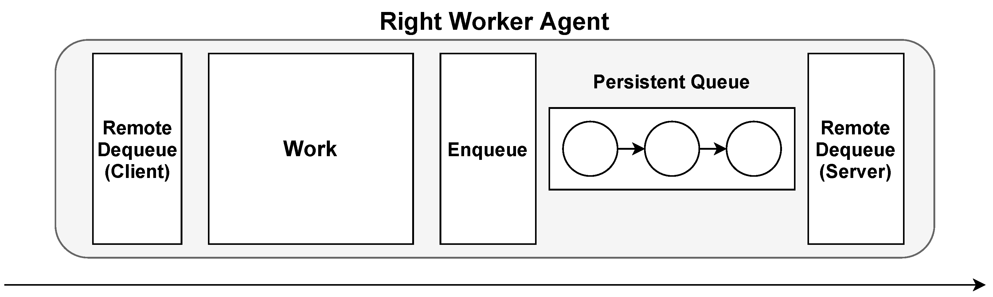
3.3.2. Right Worker Agent
The right worker agent is composed of a client on the left side and a server on the right side (see
Figure 6). This means that the agent fetches items itself from a single agent through a remote dequeue call, while items are forwarded when other agents request them.
The server on the right side enables the agent to scatter items to different agents. This is useful in situations where load balancing is required due to upcoming computation heavy work. The consequence of using the right worker agent is that the client enables it to fetch data from a single source only.
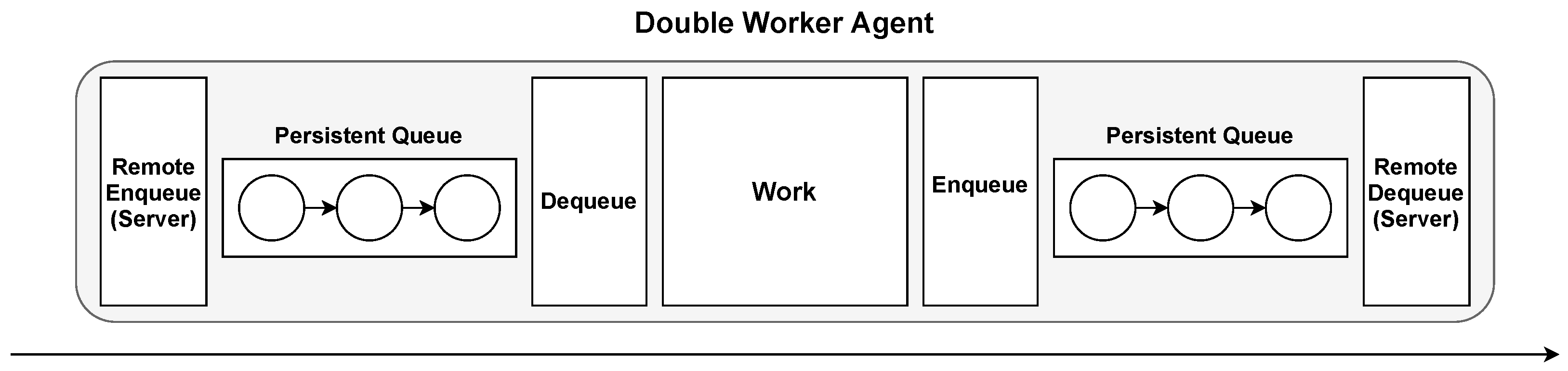
3.3.3. Double Worker Agent
This type of agent contains servers both before and after processing the item (see
Figure 7). This makes the agent completely passive, as messages are only received and forwarded through requests from other agents. This type of agent can be useful in cases where it receives messages from and scatters messages to multiple sources.
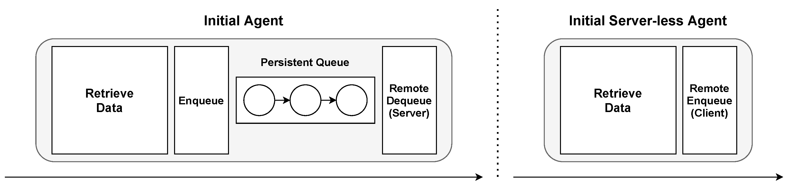
3.3.4. Initial Worker Agents
The purpose of the initial agent is to fetch data from some location in a custom manner (implemented by the application developer), before forwarding them to the next pipeline stage. The data flow is illustrated in
Figure 8. It is meant to be used as the first stage in the pipeline. Initial agents can either use a client or a server to forward items further into a pipeline. In
Section 4.5, we demonstrate how the initial server agent can be used for load balancing for counting words in a textual document.
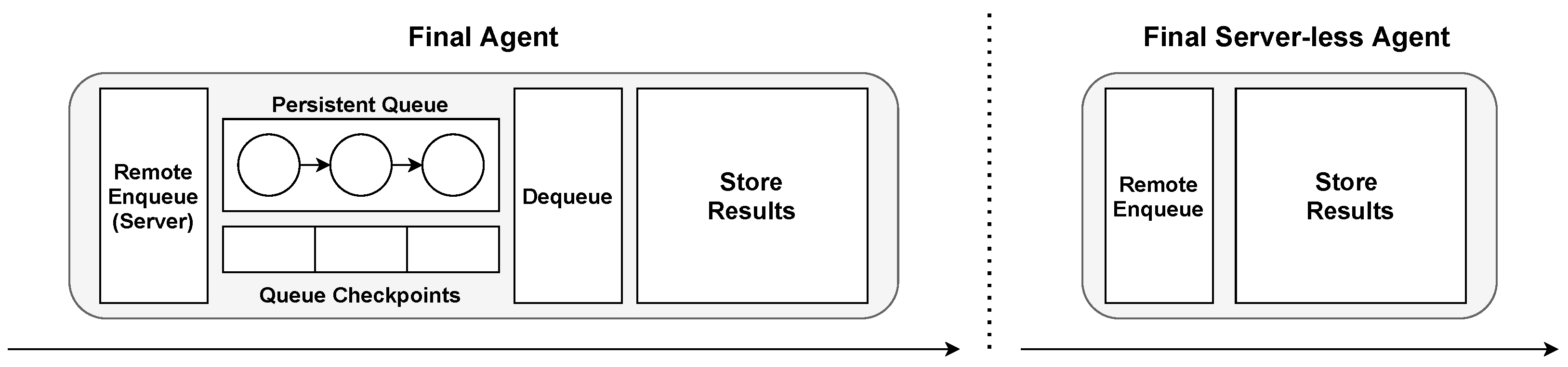
3.3.5. Final Worker Agents
The purpose of the final worker agent is to carry out the final work on an item at the end of a pipeline within the DAG. Because of this, it does not have any output queue, or client/server thread after work. The final agent can utilize a client for fetching items, or a server for receiving them. These two types of final worker agents are illustrated in
Figure 9.
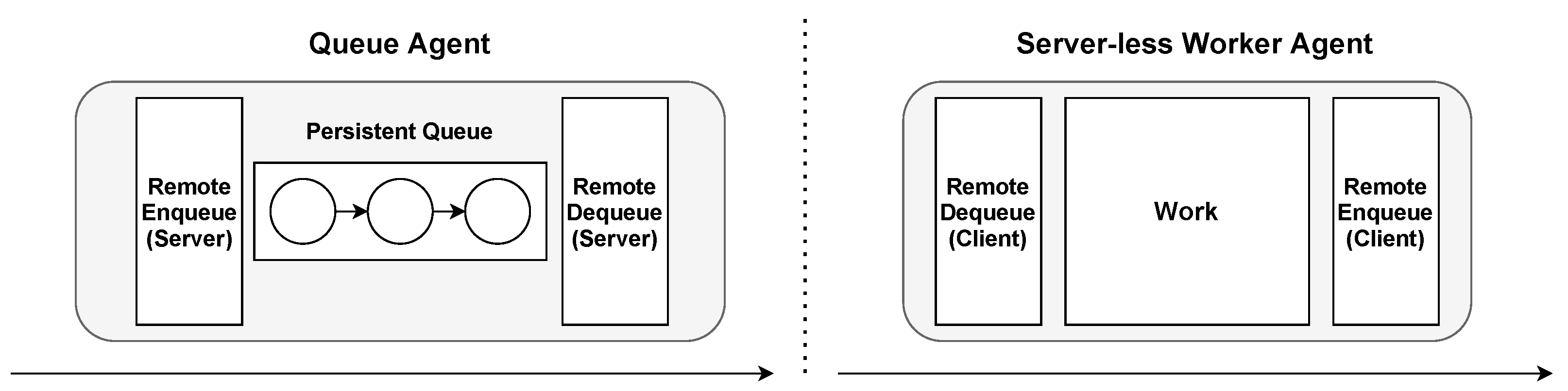
3.3.6. Queue Agent and Server-less Agent
The queue agent is only composed of one scheduling queue, which leaves the responsibility of enqueueing and dequeueing messages entirely up to other agents. It is passive, like the double queue agent, and it is also useful in similar cases where work is not required to be performed on the item in between. It can be used as a collection point for data from multiple sources that are scattered afterwards.
The server-less agent contains only clients and is therefore responsible for both fetching items from another agent and forwarding items after processing (see
Figure 10). In
Section 4.6, we demonstrate how a server-less agent can be used to retrieve items from a load balancing queue on another agent and forward the item to feature extraction models on multiple agents to increase performance.
3.4. Monitor
The remote monitor resides at a physically remote location relative to the edge system and is responsible for communicating with the system, potentially over low bandwidth. The reason for using a remote monitor is that it is not possible to fully control the physical equipment completely from an untrusted edge. The equipment is subject to potential physical harm and signal interference, and can be difficult to reach and recover.
The remote monitor is used as a safety device that resides within a safe location that can monitor the system state. By continuously communicating with a cluster controller in the system, the monitor can receive information such as which physical devices are running, if any known crashes have occurred, or additional information regarding the system. If the remote monitor fails to reach the system, it may classify this as an abnormal event and report it to system administrators or authorities. Information such as the context surrounding the failure can aid in determining the need for further investigation or inspection of the remote nodes.
3.5. File System
All nodes connect to the same distributed file system for storage and retrieval of input data and checkpoints. As data generated at edge locations can contain sensitive information, privacy agreements determining the permitted handling and use of data must be respected both by end-users and by data movement in software. The Dorvu file system [
17] is used as a storage platform for data and checkpoints in Áika for this reason.
While the communication and recovery scheme of Áika assumes the total access of requested data through a file system interface, the storage platform can enforce access control policies that respect restrictions such as the permitted geographical storage locations of files. Policies can be configured to only apply for certain files depending on the semantic information contained in them, enabling a fine-grained access control scheme. For instance, policies expressed in Dorvu can allow the transfer of files to certain locations on the condition that specific information is removed beforehand. Dorvu achieves this by executing custom policy programs at the time of file creation, and encrypting various parts of the file with different keys depending on access level. This transparently enforces policy compliance for each component in the Áika system.
4. Experimental Setup and Evaluation
In this section, we describe several experiments for evaluating the performance of Áika. All experiments are carried out at on a local Rocks cluster (version 7.0) running CentOS 7. The internal transfer rate between machines in the cluster is expected to be approximately 100 MB/s. The experiments are performed on a subset of homogeneous cluster nodes consisting of 55 Lenovo P310 computers with one Intel Core(TM) i7-6700 @ 3.40 GHz with 4 cores, 32 GB RAM, and a Nvidia GM107GL (Quadro K620) GPU each.
4.1. Micro-Benchmarks
To gain insight on the performance and overhead of the individual component of Áika and how time is spent on the various tasks, we ran several micro-benchmarks. These benchmarks are summarized in
Table 1.
We experienced that the cluster controller took approximately 300 milliseconds to start a single local controller on a separate node with an SSH client. After setting up one local controller, the time increases with approximately 150 milliseconds per additional local controller. The local controller, however, takes approximately between 20 and 40 milliseconds to start an agent. This demonstrates that the local controller not only can be used to offload the workload of the cluster controller, but can also manage to recover agents in a shorter amount of time, leading to a more efficient recovery procedure. This is especially relevant if agents shut down often.
Passing integer items from one agent to the next in a pipeline takes approximately 8 milliseconds. During this time, the item moves through two persistent queues and one TCP stream.
4.2. Persistent vs. In-Memory Queues
To understand the overhead of the persistent queues used by Áika to store information between computation steps, we measure the end-to-end throughput of the system within regular time frames at the end of a pipeline. The effects of runtime failures on performance is simulated by inducing crashes.
For these experiments, we configure Áika in a single pipeline setup consisting of one initial agent, five worker agents, and one final agent. The initial agent creates the workload data by forwarding integers into the pipeline. Worker agents retrieve and increment these integers before forwarding them to the next pipeline steps. To simulate work time, a worker agent may also sleep after an integer has been incremented. The final agent receives the data and increments its counter of received requests. A separate processing thread writes the number of requests received every five seconds to a log file. By batching these disk writes, we reduce the impact measurement logging has on system performance.
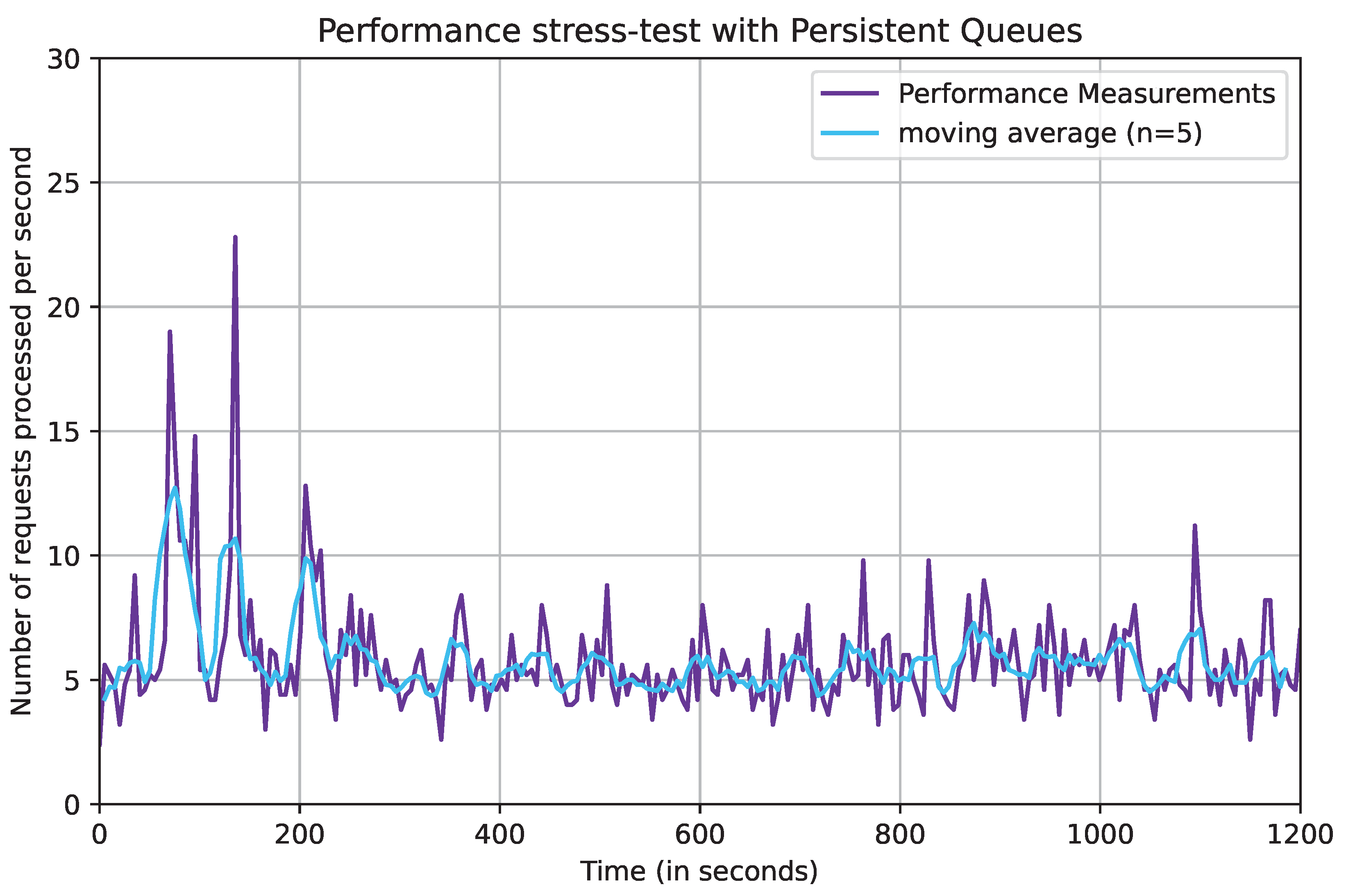
The observed number of requests received when running the pipeline configuration for 1200 s (20 min) can be seen in
Figure 11. Because the data are highly varied, the figure also includes the moving average using a sliding window size of
.
From the figure, we can observe that the system has a high throughput in the initial stages of the process, before it becomes relatively stable at around 250 s, where the number of requests processed ranges between four and eight requests per second. This demonstrate the system’s maximum throughput on our current hardware infrastructure.
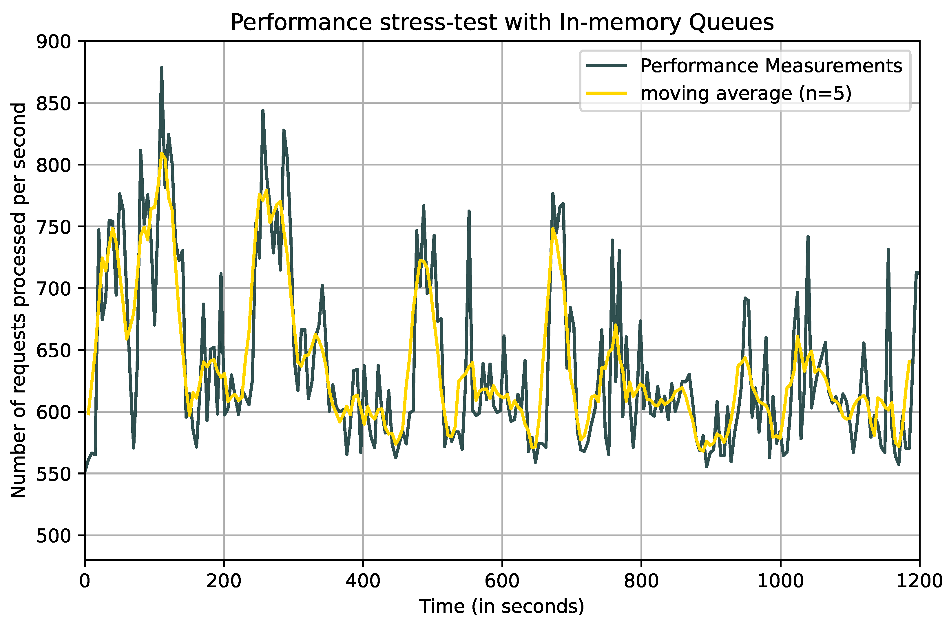
Next, we perform a similar experiment, but using in-memory queues in the agents instead of persistent disk-based queues. The in-memory queue is configured to hold a maximum of 100 items. The observed end-to-end throughput is plotted in
Figure 12.
As can be observed in the figure, the system clearly has a higher performance when using in-memory queues. This is not unexpected, as any form of computation on a data item should be performed faster when the item is fetched from volatile memory instead of disk. The figure shows that the performance with in-memory queues can be up to 100 times better compared to the system with persistent queues.
4.3. Computationally Demanding Workloads
To simulate applications with a higher computational load, we configure each worker to sleep for between 0.9 and 1.1 s before incriminating and forwarding the integers. The observed throughput is shown in
Figure 13 for both persistent queues and in-memory queues.
Contrary to our previous observations, persistent queues performs better than in-memory queues when jobs are more computationally demanding. The performance also appears more stable, ranging mostly between 0.6 and 1 request per second for persistent queues and between 0.4 and 1 requests per second for in-memory queues.
The results illustrate that the overhead created when writing the queues to file continuously becomes negligible with regards to the overall performance. Despite this, the queues for these measurements only contain integers. With such small values, the time spent writing to file will be significantly reduced compared to, for instance, images. It is therefore important to consider the size of the data when working out a system configuration with optimal performance for carrying out the desired task.
4.4. Failure Experiment
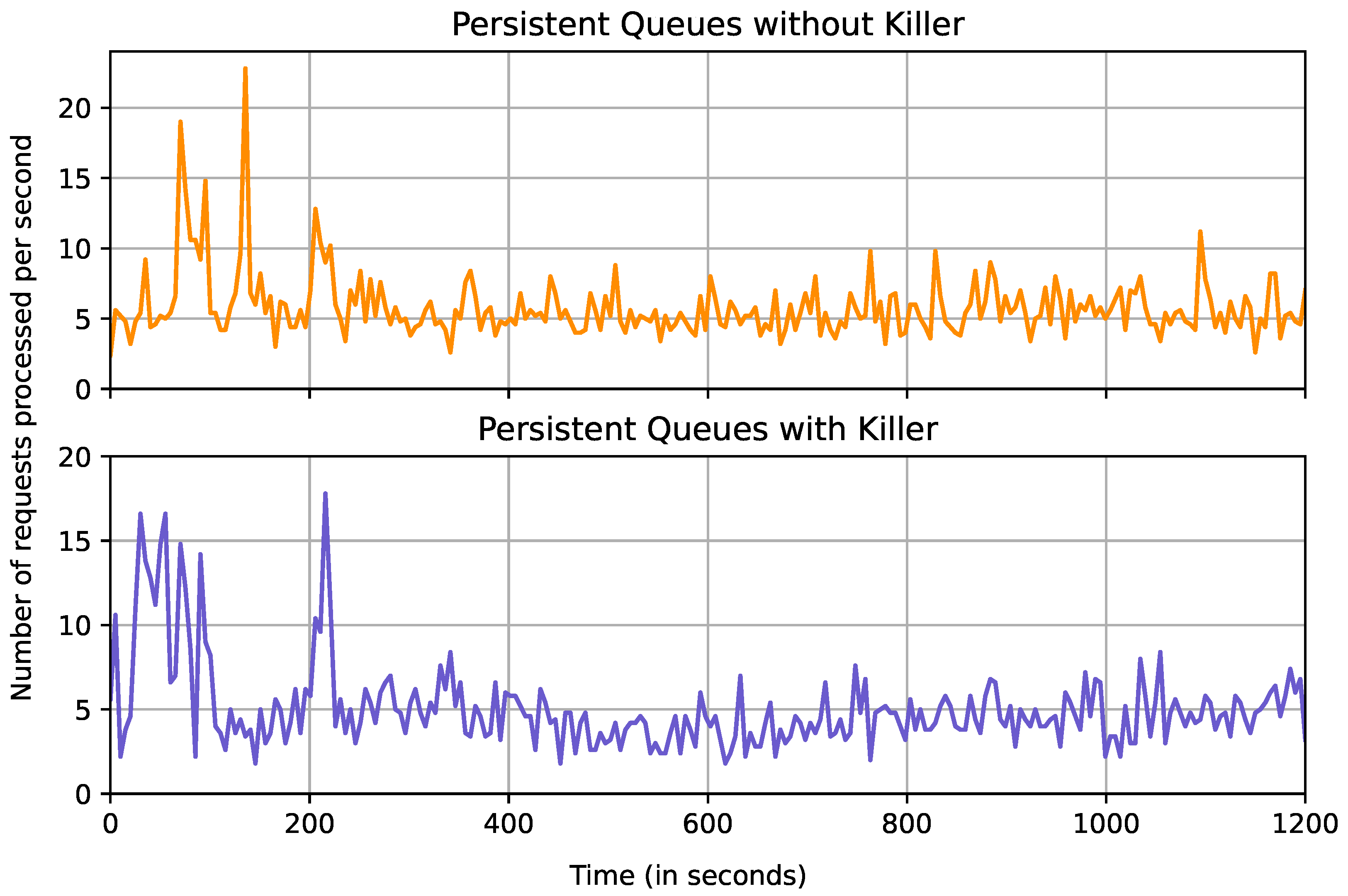
The purpose of the failure experiment is to gain insight into how the performance is affected when working agents are being regularly shut down. We also investigate to what degree the system manages to remain stable when agents are being shut down and recovered.
Figure 14 illustrates the different performance results obtained when stress testing the system while simulating failures. In our failure simulation experiments, a Killer process is instructed to pick one random worker agent or initial agent at 15 s intervals and terminate that process. The Killer runs for the entire duration of the experiment when deployed.
Measurements with and without the Killer process are similar both in terms of the series shape and the performance. When the Killer is deployed, the measurements do, however, become slightly worse. Despite the agents being terminated every 15 s, the performance still remains relatively similar in terms of stability. Agents being terminated every 15 s and the number of requests received being measured every 5 s means that the performance should decrease in every third measurement. This could explain the lack of visible dips in performance.
Table 2 summarizes the observation for the various experiments. These measurements confirm the overhead created when using persistent queues becomes negligible when the workload is increased. Not only are the results more stable for persistent queues (standard deviation 0.18 versus 0.22), it also performs better overall with an average of 0.88 requests processed per second compared to 0.80 s for the in-memory queue. The performance does decrease slightly, from 5.82 requests per second during the stress test to 5.08 requests per second during the same test with the Killer component deployed. The stability of the system also seems to decrease slightly, as the standard deviation changes from 2.29 to 2.58 requests per second when the Killer component is deployed.
It is important to note that despite the performance gain from using in-memory queues, the potential consequence of this is that the system remains unable to properly recover from faults if any component shuts down during the runtime. A local controller may resume an agent that crashes, enabling it to continue working. When using in-memory queues, the data stored will, however, be lost if the agent itself is to crash. This requires a complex recovery routine, where the agent initializing the pipeline has to re-retrieve the specific items that have been lost during the crash and propagate them through the entire pipeline all over again. In the case where the system operates in a trusted environment where the runtime does not last long or is communication intensive, it could benefit the user to use in-memory queues in favor of persistent queues.
The observations in
Figure 14 show that Áika provides a stable performance despite worker agents being terminated. The local controllers are constantly monitoring the agents and could therefore explain why the system manages to remain stable. Despite this, the performance of the system is still affected, and having processes killed between small intervals could be fatal for the performance of the system.
4.5. Distributed Word Counter
To evaluate if Áika can handle simple analytical tasks that do not necessarily involve highly complex computations, we deploy a distributed application with a computation pipeline that follows a MapReduce pattern. While MapReduce-computations are often conceptually simple, specialized frameworks for expressing these problems are needed to orchestrate data distribution, parallelization, and failure handling [
28]. To implement a MapReduce-like problem on Áika, we deploy a distributed word-counting application. The application counts the words contained in the input text file. The input dataset is generated by sampling random words from the list of the 1000 most common words in the English language according to Education First [
29]. The purpose of this experiment is to show that Áika can be configured to express and perform general MapReduce-like operations. Three types of agents are used:
Split worker divides into distinct and independent units.
Map workers tokenize input text and iterate counting every word.
The counted values are stored in a simple Python dictionary.
Reduce workers combine input dictionaries from the mappers into a total dictionary.
We configure Áika to use a single splitter to initialize the word counting, between 1 and 16 number of mappers, and a single reducer that combines the results from all the mappers. The system is configured with static load balancing, where each map worker fetches one job from the split workers queue, respectively. This also means that each worker performs their work in one single iteration. The experiment is repeated 15 times so that the stability of the system can be measured as well.
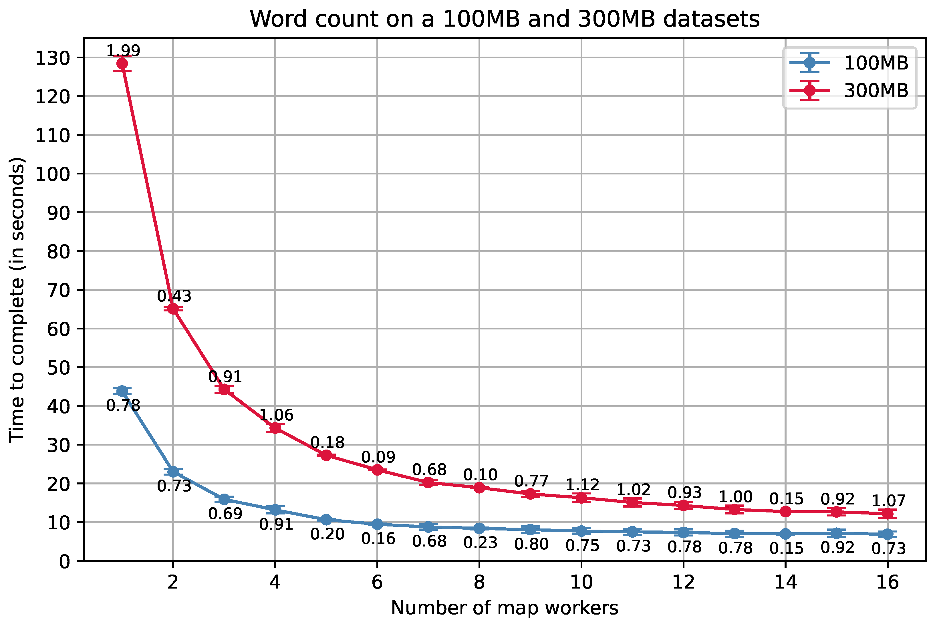
The results obtained from running word counting on a 100 MB and a 300 MB dataset can be found in
Figure 15. The figure indicates that the system is able to scale well in terms of handling embarrassingly parallel algorithms, due to the slope having an expected concave shape. Despite this, the slope starts to flatten at around 8–9 s. One reason for this is that creating more map workers is more time consuming for the system, as the workers are instantiated by local controllers, which are further instantiated from a single cluster controller. In addition to this, the use of a single reducer could lead to a minor bottleneck, since it is responsible for combining results from all map workers.
As the micro-benchmarks shows, the cluster controller spends approximately 0.30 s starting up a single local controller. Afterwards, it spends approximately 0.15 s extra for each additional local controller. The local controller, on the other hand, spends approximately between 0.02 and 0.04 s to start a single agent. This in total makes up over 1 s of overhead when the number of map workers is six or more, which partly explains the overhead observed in the graph. Furthermore, it is necessary to take into account communication overhead, file reading and writing (due to the persistent queues), and the startup wait time for each agent. A part of the overhead could also be explained by the fact that each mapper loads their entire partition into memory before mapping. When the size of the dataset increases, the overhead may therefore also increase.
4.6. Distributed Deep Feature Extraction
The purpose of the Distributed Deep Feature Extraction experiment is to evaluate Áika’s ability to extract features from image data with multiple deep learning models, using two approaches. Another purpose of the experiment is to investigate the system’s ability to scale with these two approaches.
For these experiments, we use the STL-10 image dataset to perform the feature extractions [
30]. The STL-10 dataset is inspired by the CIFAR-10 dataset [
31], although there are some differences between them, such as the images having a higher resolution (
instead of
). The feature extractions are performed on the entire dataset of 113,000 images in batches, with 500 images per batch. The use of batches could give an indication of how the system performs with larger scaled images.
The system extracts features from the data with the use of three pre-trained Keras [
32] models. We evaluate two different approaches:
All three models are loaded into N workers that perform feature extraction on all three models, sequentially.
The three models are distributed among three workers, such that the feature extraction process can be performed in parallel (This experiment was performed on CPUs instead of GPUs due to compatibility issues).
The sequential feature extraction graph consists of an initial agent that divides work among a set of workers. Each worker extracts features from the given data with three feature extraction models, sequentially. The distributed feature extraction graph replaces the workers with a sub-graph where each feature extraction model is put on a respective worker. This enables the feature extraction process to be performed in parallel.
Feature extractions on all 113,000 images take approximately 3336 s when configured to run on a single machine. This experiment was repeated three times. The computation time for the same task run on Áika in batches of 500 images using the two approaches described above can be found in
Figure 16. Both approaches seem to scale at a similar rate in terms of number of sub-graphs. The distributed feature extraction approach is clearly more efficient, but also requires more workers.
One interesting finding is that the sequential feature extraction approach performs better compared to the single machine benchmark, even when using a single worker. At the data point with one sub-graph, the sequential feature extraction experiment has the same work distribution as the single machine benchmark, while expected to have additional overhead that the sequential feature extraction approach receives due to latency. The reason could also be due to varying processing frequency or memory management in Python.
These experiments show that Áika’s method of distributing the feature-extraction models across several workers is beneficial for performance. It is, however, important to note that the distribution sub-graph requires three workers instead of a single one. The results from running the experiment with three single workers instead of a sub-graph of three workers proves to be more beneficial in terms of pure performance. The reason for this is that the VGG-16 model spends more time extracting features compared to the other two models, which makes the system scale less evenly. However, if the system was to further utilize a classifier that blocks until all features extracted for the batch of data have been received, the distributed approach may prove to be more beneficial for rapidly classifying features.
5. Conclusions
Monitoring of resources in world oceans and the Arctic is a technological challenge that requires domain-specific systems. The edge environments that offshore fishing vessels traverse are characterized by their lack of stable connections, high latency, low bandwidth, and difficulty of manual intervention. This paper describes Áika: a prototype system for executing distributed AI applications in these domain-specific edge environments. We investigate how a system supporting AI inference in these environments can be built to support a wide range of computational graphs through a DAG computation model, while making the system tolerant to failures.
Áika provides application developers with generalized building blocks that can be used to construct complex distributed computational tasks with robustness and privacy properties. Through a hierarchical design, we utilize local controllers on physical nodes to perform quick recovery when failure occurs. A cluster controller is used to further invoke node recovery, where agents from a failed physical node are moved to a replica. The cluster controller is replicated in a chain to avoid having a single point of failure, and communicates with a remote monitor that logs failures and classifies the system state when sufficient bandwidth is available.
Our experimental evaluations demonstrate that Áika has a stable throughput despite potential agent crashes. For data-intensive tasks, we show that persistent queues can be beneficial compared to in-memory queues, in cases where the workload on an item exceeds the time spent transporting the item. We demonstrate how Áika can be used to create DAGs of varying complexity with load balancing, and distribute work among agents to optimize performance. We implement two experiments with computational tasks relevant for the targeted domain, namely a MapReduce task and a deep-learning-based feature extraction task. The results from these experiments demonstrate that Áika is scalable and supports different computational graph designs that can be used in the domain of fishery monitoring and surveillance.
Author Contributions
Conceptualization, J.A.A., A.B.O. and D.J.; methodology, J.A.A. and D.J.; software, J.A.A. and A.B.O.; validation, J.A.A., investigation, J.A.A., A.B.O. and D.J.; data curation, J.A.A.; writing—original draft preparation, J.A.A. and M.A.R.; writing—review and editing, J.A.A., A.B.O., T.-A.S.N., H.D.J., M.A.R., P.H. and D.J.; visualization, J.A.A.; supervision, H.D.J. and D.J.; project administration, H.D.J., M.A.R., P.H. and D.J.; funding acquisition, H.D.J. and D.J. All authors have read and agreed to the published version of the manuscript.
Funding
This work is partially funded by the Research Council of Norway project numbers 274451 and 263248, and Lab Nord-Norge (“Samfunnsløftet”).
Institutional Review Board Statement
Not applicable.
Informed Consent Statement
Not applicable.
Data Availability Statement
Not applicable.
Conflicts of Interest
The authors declare no conflict of interest. The funders had no role in the design of the study; in the collection, analyses, or interpretation of data; in the writing of the manuscript, or in the decision to publish the results.
References
- Stoica, I.; Song, D.; Popa, R.A.; Patterson, D.A.; Mahoney, M.W.; Katz, R.H.; Joseph, A.D.; Jordan, M.; Hellerstein, J.M.; Gonzalez, J.; et al. A Berkeley View of Systems Challenges for AI; Technical Report UCB/EECS-2017-159; EECS Department, University of California: Berkeley, CA, USA, 2017. [Google Scholar]
- Carcillo, F.; Le Borgne, Y.A.; Caelen, O.; Kessaci, Y.; Oblé, F.; Bontempi, G. Combining unsupervised and supervised learning in credit card fraud detection. Inf. Sci. 2021, 557, 317–331. [Google Scholar] [CrossRef]
- Deng, S.; Zhao, H.; Yin, J.; Dustdar, S.; Zomaya, A.Y. Edge Intelligence: The Confluence of Edge Computing and Artificial Intelligence. IEEE Internet Things J. 2020, 7, 7457–7469. [Google Scholar] [CrossRef] [Green Version]
- Liu, J.; Sheng, M.; Liu, L.; Li, J. Network Densification in 5G: From the Short-Range Communications Perspective. IEEE Commun. Mag. 2017, 55, 96–102. [Google Scholar] [CrossRef] [Green Version]
- European Union. Regulation (EU) 2016/679 of the European Parliament and of the Council of 27 April 2016 on the protection of natural persons with regard to the processing of personal data and on the free movement of such data, and repealing Directive 95/46/EC (General Data Protection Regulation). Off. J. Eur. Union 2016, 119, 1–88. [Google Scholar]
- Costello, C.; Cao, L.; Gelcich, S.; Cisneros-Mata, M.A.; Free, C.M.; Froehlich, H.E.; Golden, C.D.; Ishimura, G.; Maier, J.; Macadam-Somer, I.; et al. The future of food from the sea. Nature 2020, 588, 95. [Google Scholar] [CrossRef] [PubMed]
- UNODC. Fisheries Crime: Transnational Organized Criminal Activities in the Context of the Fisheries Sector; UNODC: Vienna, Austria, 2016. [Google Scholar]
- Ministry of Trade, Industry and Fisheries. Framtidens Fiskerikontroll; NOU 21:19; Ministry of Trade, Industry and Fisheries: Oslo, Norway, 2019.
- Márcia Bizzotto. Fishing Rules: Compulsory CCTV for Certain Vessels to Counter Infractions. European Parliament Press Release. Available online: https://www.europarl.europa.eu/news/en/press-room/20210304IPR99227/fishing-rules-compulsory-cctv-for-certain-vessels-to-counter-infractions (accessed on 8 August 2021).
- Ingilæ, Ø. Fiskere Settes Under Overvåkning. Kyst og Fjord. Available online: https://www.kystogfjord.no/nyheter/forsiden/Fiskere-settes-under-overvaakning (accessed on 8 August 2021).
- Martinussen, T.M. Danske Fiskere Samler Seg Mot Kamera-overvåKning i Fiskeriene. Fiskeribladet. Available online: https://www.fiskeribladet.no/nyheter/danske-fiskere-samler-seg-mot-kamera-overvakning-i-fiskeriene/2-1-839478 (accessed on 8 August 2021).
- Nordmo, T.A.S.; Ovesen, A.B.; Johansen, H.D.; Riegler, M.A.; Halvorsen, P.; Johansen, D. Dutkat: A Multimedia System for Catching Illegal Catchers in a Privacy-Preserving Manner. In Proceedings of the 2021 Workshop on Intelligent Cross-Data Analysis and Retrieval, Taipei, Taiwan, 21 August 2021; Association for Computing Machinery: New York, NY, USA, 2021; pp. 57–61. [Google Scholar] [CrossRef]
- van Helmond, A.T.; Mortensen, L.O.; Plet-Hansen, K.S.; Ulrich, C.; Needle, C.L.; Oesterwind, D.; Kindt-Larsen, L.; Catchpole, T.; Mangi, S.; Zimmermann, C. Electronic monitoring in fisheries: Lessons from global experiences and future opportunities. Fish Fish. 2020, 21, 162–189. [Google Scholar] [CrossRef]
- Ananthanarayanan, G.; Bahl, P.; Bodík, P.; Chintalapudi, K.; Philipose, M.; Ravindranath, L.; Sinha, S. Real-time video analytics: The killer app for edge computing. Computer 2017, 50, 58–67. [Google Scholar] [CrossRef]
- Fitwi, A.; Chen, Y.; Zhu, S.; Blasch, E.; Chen, G. Privacy-preserving surveillance as an edge service based on lightweight video protection schemes using face de-identification and window masking. Electronics 2021, 10, 236. [Google Scholar] [CrossRef]
- Dsouza, S.; Bahl, V.; Ao, L.; Cox, L.P. Amadeus: Scalable, Privacy-Preserving Live Video Analytics. arXiv 2020, arXiv:2011.05163. [Google Scholar]
- Ovesen, A.B.; Nordmo, T.A.S.; Johansen, H.D.; Riegler, M.A.; Halvorsen, P.; Johansen, D. File System Support for Privacy-Preserving Analysis and Forensics in Low-Bandwidth Edge Environments. Information 2021, 12, 430. [Google Scholar] [CrossRef]
- Harchol, Y.; Mushtaq, A.; McCauley, J.; Panda, A.; Shenker, S. CESSNA: Resilient Edge-Computing. In Proceedings of the 2018 Workshop on Mobile Edge Communications, Budapest, Hungary, 20 August 2018; Association for Computing Machinery: New York, NY, USA, 2018; pp. 1–6. [Google Scholar] [CrossRef]
- Wang, C.; Gill, C.; Lu, C. FRAME: Fault Tolerant and Real-Time Messaging for Edge Computing. In Proceedings of the 2019 IEEE 39th International Conference on Distributed Computing Systems (ICDCS), Dallas, TX, USA, 7–9 July 2019; pp. 976–985. [Google Scholar] [CrossRef]
- Harrison, T.H.; Levine, D.L.; Schmidt, D.C. The Design and Performance of a Real-Time CORBA Event Service. SIGPLAN Not. 1997, 32, 184–200. [Google Scholar] [CrossRef]
- Johansen, D.; Marzullo, K.; Schneider, F.; Jacobsen, K.; Zagorodnov, D. NAP: Practical fault-tolerance for itinerant computations. In Proceedings of the 19th IEEE International Conference on Distributed Computing Systems (Cat. No.99CB37003), Austin, TX, USA, 5 June 1999; pp. 180–189. [Google Scholar] [CrossRef] [Green Version]
- Schneider, F.B.; Gries, D.; Schlichting, R.D. Fault-tolerant broadcasts. Sci. Comput. Program. 1984, 4, 1–15. [Google Scholar] [CrossRef] [Green Version]
- Leners, J.; Wu, H.; Hung, W.L.; Aguilera, M.; Walfish, M. Detecting failures in distributed systems with the Falcon spy network. In Proceedings of the Twenty-Third ACM Symposium on Operating Systems Principles, Cascais, Portugal, 23–26 October 2011; pp. 279–294. [Google Scholar]
- Isard, M.; Budiu, M.; Yu, Y.; Birrell, A.; Fetterly, D. Dryad: Distributed Data-Parallel Programs from Sequential Building Blocks. SIGOPS Oper. Syst. Rev. 2007, 41, 59–72. [Google Scholar] [CrossRef]
- Dean, J.; Ghemawat, S. MapReduce: Simplified Data Processing on Large Clusters. In Proceedings of the OSDI’04: Sixth Symposium on Operating System Design and Implementation, San Francisco, CA, USA, 6–8 December 2004; pp. 137–150. [Google Scholar]
- Valvåg, S.V.; Johansen, D.; Kvalnes, Å. Cogset: A high performance MapReduce engine. Concurr. Comput. Pract. Exp. 2013, 25, 2–23. [Google Scholar] [CrossRef] [Green Version]
- Welsh, M.; Culler, D.; Brewer, E. SEDA: An Architecture for Well-Conditioned, Scalable Internet Services. SIGOPS Oper. Syst. Rev. 2001, 35, 230–243. [Google Scholar] [CrossRef]
- Dean, J.; Ghemawat, S. MapReduce: Simplified data processing on large clusters. Commun. ACM 2008, 51, 107–113. [Google Scholar] [CrossRef]
- 1000 Most Common Words in English. 2011. Available online: https://www.ef.com/wwen/english-resources/english-vocabulary/top-1000-words/ (accessed on 11 November 2021).
- Coates, A.; Ng, A.; Lee, H. An analysis of single-layer networks in unsupervised feature learning. In Proceedings of the Fourteenth International Conference on Artificial Intelligence and Statistics, Fort Lauderdale, FL, USA, 11–13 April 2011; pp. 215–223. [Google Scholar]
- Krizhevsky, A. Learning Multiple Layers of Features from Tiny Images; Citeseer: Princeton, NJ, USA, 2009. [Google Scholar]
- Keras: Deep Learning for Humans. 2015. Available online: https://github.com/fchollet/keras (accessed on 28 April 2022).
Figure 1.
Áika’s architecture. Arrows represent client/server communication. Red arrows represent communication that may only occur during recovery. The figure does not include communication between agents. All nodes in the cluster are connected to a distributed file system that enables file sharing across the nodes. This is practical for recovery.
Figure 2.
The general process structure of Áika’s components. Each process is organized in a hierarchy of threads, where a main thread starts several child threads. Child threads are restarted by the main thread if they fail. Servers spawn multiple request handler threads to enable requests from multiple sources to be handled concurrently.
Figure 3.
The cluster controller is replicated and connected in a chain.
Figure 3.
The cluster controller is replicated and connected in a chain.
Figure 4.
Shows the general structure of the agents.
Figure 4.
Shows the general structure of the agents.
Figure 5.
Left worker agent. A worker agent that dequeues messages from a local queue before the analysis process, but enqueues the result remotely.
Figure 5.
Left worker agent. A worker agent that dequeues messages from a local queue before the analysis process, but enqueues the result remotely.
Figure 6.
Right worker agent. A worker agent that dequeues messages from a remote queue before the analysis process, but enqueues the result on a local queue.
Figure 6.
Right worker agent. A worker agent that dequeues messages from a remote queue before the analysis process, but enqueues the result on a local queue.
Figure 7.
Double worker agent. A worker agent containing servers both before and after processing the item.
Figure 7.
Double worker agent. A worker agent containing servers both before and after processing the item.
Figure 8.
Initial worker agents. This type of agent is used to initiate one or several pipelines. This is achieved by having the agent continuously retrieve data from a source and then forward it to either a local (see left figure), or a remote (see right figure) queue.
Figure 8.
Initial worker agents. This type of agent is used to initiate one or several pipelines. This is achieved by having the agent continuously retrieve data from a source and then forward it to either a local (see left figure), or a remote (see right figure) queue.
Figure 9.
Final worker agents. This type of agent is used to finalize one or several pipelines. The agent retrieves the end results from either a local or a remote queue, then handles the result in a customized manner.
Figure 9.
Final worker agents. This type of agent is used to finalize one or several pipelines. The agent retrieves the end results from either a local or a remote queue, then handles the result in a customized manner.
Figure 10.
Queue agent and server-less worker agent. The agent to the left contains a single queue without any analysis. The agent to the right does not have any servers and receives items by making requests through clients on both sides.
Figure 10.
Queue agent and server-less worker agent. The agent to the left contains a single queue without any analysis. The agent to the right does not have any servers and receives items by making requests through clients on both sides.
Figure 11.
The obtained results from stress-testing the system with persistent queues over the course of 1200 s. The number of requests are measured and reset every 5 s. The plot shows the average number of requests processed per second over each 5 s interval. The moving average is computed with a window size .
Figure 12.
The results obtained by stress testing the system with in-memory queues over the course of 1200 s. Number of requests are measured and reset every 5 s. The plot shows the average number of requests processed per second over each 5 s interval. The moving average is computed with a window size .
Figure 13.
Results obtained when measuring the number of requests received where worker agents in the pipeline sleep for one second after processing an item. Measurements are carried out with persistent queues (top) and in-memory queues (bottom). The number of requests received is measured and reset every 5 s. The plot shows number of requests per second over each 5 s interval.
Figure 14.
Results obtained when measuring the number of requests received during stress-testing over the course 1200 s without (top) and with (bottom) the killer deployed. The number of requests received is measured and reset every 5 s. The plot shows the average number of requests per second over each 5 s interval.
Figure 15.
Results obtained from counting the words in datasets with sizes of 100 MB and 300 MB. Standard deviation is shown as an error bar, and the corresponding standard deviation value is displayed above each data point.
Figure 15.
Results obtained from counting the words in datasets with sizes of 100 MB and 300 MB. Standard deviation is shown as an error bar, and the corresponding standard deviation value is displayed above each data point.
Figure 16.
Results obtained from performing feature extraction with pre-trained VGG-16, DenseNet-121, and ResNet-50 models, where the models are either distributed among three workers (Distributed Feature Extraction), or put in a sequence on a single worker (Sequential Feature Extraction). The images have been processed with a batch size of 500. The standard deviation is shown as an error bar and value at each data point.
Table 1.
Results from micro-benchmarks.
Table 1.
Results from micro-benchmarks.
| Micro-Benchmark | Time (milliseconds) |
|---|
| Local Controller Initial Startup | 300 |
| Local Controller Further Startup | 150 (per local controller after the first) |
| Agent Startup | 20–40 |
| Pass integer item from agent to agent | 7–9 |
Table 2.
A summary derived from the continuous performance experiments explained previously. The table contains the minimum, maximum, mean, median, and standard deviation of all requests per second measured for each benchmark.
Table 2.
A summary derived from the continuous performance experiments explained previously. The table contains the minimum, maximum, mean, median, and standard deviation of all requests per second measured for each benchmark.
| Queue Type Used | Min Value | Mean Value | Standard Deviation | Median Value | Max Value |
|---|
| Persistent Queue (No sleep) | 2.40 | 5.82 | 2.29 | 5.40 | 22.80 |
| In-memory Queue (No sleep) | 551.40 | 636.89 | 68.67 | 612.30 | 878.60 |
| Persistent Queue (Kill every 15 s) | 1.8 | 5.08 | 2.58 | 4.6 | 17.8 |
| Persistent Queue (Sleep 0.9–1.1 s) | 0 | 0.88 | 0.18 | 1 | 1.2 |
| In-memory Queue (Sleep 0.9–1.1 s) | 0 | 0.80 | 0.22 | 0.8 | 1.2 |
| Publisher’s Note: MDPI stays neutral with regard to jurisdictional claims in published maps and institutional affiliations. |
© 2022 by the authors. Licensee MDPI, Basel, Switzerland. This article is an open access article distributed under the terms and conditions of the Creative Commons Attribution (CC BY) license (https://creativecommons.org/licenses/by/4.0/).


 ,
, 


