Modeling and Simulating the Static Structural Response and Lift Off of a Preloaded Bolted Joint on a Flange †


Department of Mechanical Engineering, College of Engineering, Umm Al-Qura University, Makkah 24224, Saudi Arabia
†
Presented at the 14th International Conference on Interdisciplinarity in Engineering—INTER-ENG 2020, Târgu Mureș, Romania, 8–9 October 2020.
Proceedings 2020, 63(1), 10; https://0-doi-org.brum.beds.ac.uk/10.3390/proceedings2020063010
Published: 11 December 2020
(This article belongs to the Proceedings of The 14th International Conference on Interdisciplinarity in Engineering—INTER-ENG 2020)
Abstract
:The present paper describes the structural analysis performed on a preloaded bolted joint. The first joint modeled was comprised of a conventional cylindrical flange that was sliced to simplify the analysis for two bolts in lieu of four. This involved an L-shaped flat segment flange. Parametric studies were performed using elastic, large-deformation, non-linear finite element analysis to determine the influence of several factors on the bolted-joint response. The factors considered included bolt preload, contact surfaces, edge boundary conditions, and joint segment length in this first approach. The second model applied the previous preloaded torque on a complex flange to study the flange lift off. Joint response is reported in terms of displacements, gap opening, and surface strains. Most of the factors studied were determined to have minimal effect on the bolted joint response.
1. Introduction
In the International Journal of Mechanical Engineering, Welch argues that the preloaded (or pre-tensioned) bolted joints are sufficiently tightened to create joint closure while aligning the connecting components, which are tightened further to yield the required bolt preload and (more critically) a faying surface compressive load [1]. The faying face of a joint section is the prepared face (fabricated or ground) that connects with the faying face of a different joint component. Preloaded joints are essential in providing stiff joints that do not slip. The bolts possess substantial mean stress but have a lower range of working stress, which confers preloaded joints excellent fatigue functionality. Therefore, this research aims at analyzing the structural response and preloaded bolt joint lift off on flanges based on Welch argument [1].
We used elastic, large-deformation, non-linear finite element analysis to achieve this goal. We used two kinds of flanges to implement the technique: An L-shaped flat section flange and a sophisticated flange. The investigation was simulated using Ansys Workbench, while the Inventor Autodesk was used to build the geometry.
According to Oldfield and to Knight, eccentric loading to the fasteners greatly facilitates the separation of bolted joints. Such behavior of joints increases the possibility of bolt fatigue, principally because of the moments the bolts carry during lifting [2,3]. Thoppul and Somasundaram contend that many traditional flanges exert some quantity of eccentric weight on the fasteners [4,5].
Integrated Systems Research, Inc. analyzed the reaction of eccentrically loaded bolted joints by investigating the relative advantages of different features of joints on increasing separation resistance [6]. There was a presentation of the findings of surface analysis behavior of traditional cylindrical design of a flange. Just like any vital bolted connection, finite element analysis should be used to finalize the preliminary design.
The study should integrate any safety issues, partial safety issues, and design factors, or allowable design stresses and loads requirement of the local regulations during the design of the equipment to satisfy specific needs and should precede any similar considerations that this paper proposes.
2. Materials and Methods
2.1. Joint Arrangement
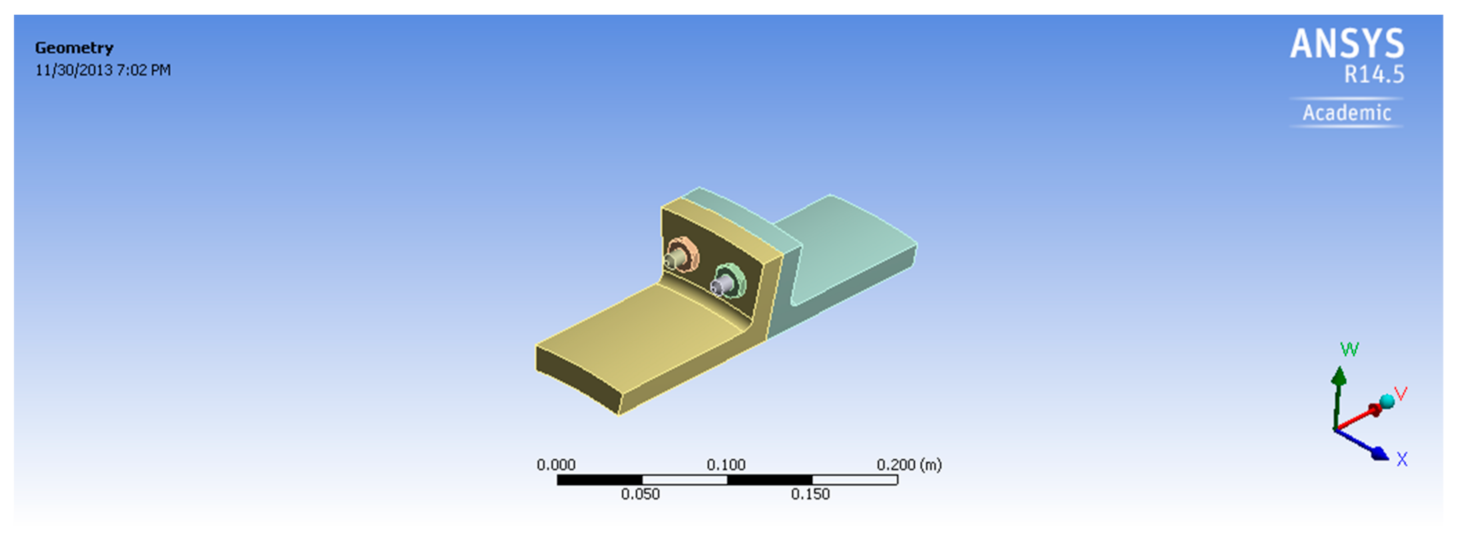
Figure 1 illustrates the configuration of the preloaded bolted joint. It has two 5-inch flange sections of 0.656-inch-thick material. A 3/8-inch-diameter bolt in a large-diameter cylindrical casing is used to connect the flange specimens. It is normal not to know the exact preload force of the bolt. Nevertheless, the estimated preload torque was 300–600 ft-lb. The flanges were split for the simulation to be conducted using just two bolts to simplify the investigation.
2.2. Material Characteristics
It was assumed that the bolted joint material was (ABI 5L X52) carbon steel, which yielded 52 ksi of stress [7]. Because elastoplastic investigations were expected, it needed the material information as a type of actual stress being the function of plastic stress [8]. Medium carbon steel (SAE Grade 5), which yielded strain of 120 ksi, was assumed to be the material for the bolts and nuts [7]. The bolts and nuts in these investigations were postulated to have a linear elastic response and thus had no explicit modeling.
2.3. Stress Estimation in a Bolt
An evaluation of bolt stress depends on a simple material strength technique for the bolt and speculates a maximum use of bolt material before damage or failure, for instance, when the entire bolt cross-sectional area produces stress. The assumptions of bolt preload constitute a particular preload torque T. Preload Axial force, F, relates to the preload torque [9] as:
where k is a nut factor to account for threads friction between nut and bolts [10]. d is the bolt diameter. For permanent links:
where Sp is the bolt’s strength; At, the area of tensile stress, can be illustrated as:
where d represents the nominal diameter in inches, while n is thread numbers in each inch (pitch).
T = k × F × d,
F = 0.9 × At × Sp,
At = 0.7854 × (d − 0.9743/n)2,
A preloaded bolt with an axial force of 5927 lb produces a nominal preload torque of 444 ft-lb and a nut factor of 0.2. The force gives the initial bolt stress because of the preload of 92 ksi. Thus, the full stress of the bolt is calculated as the total of the stresses from the mechanical loads and preload stresses. Therefore, the total estimation of the bolt stress is 70 ksi. This result is entirely below the bolt material yield stress of 120 ksi. The definition of developing bolt yield force is a preload force capable of completing the cross-sectional yielding of a bolt (i.e., bolt yield stress multiplied by the cross-sectional area of the bolt), which equals 53,000 lb.
2.4. Assumptions During Modeling
The development of these stress analysis models has several common assumptions. This simulation makes two key assumptions that should be discussed. First, the finite components did not have an explicit representation of the bolts and nuts; their effect was rather simulated. One-dimensional elastic beams represented the bolts. Second, the efforts to compute the finite element models were lowered by splitting the flange for the analysis of just two bolts as Figure 1 indicates. This reduced the CPU processing time and simplified the investigation.
3. Method of Analysis
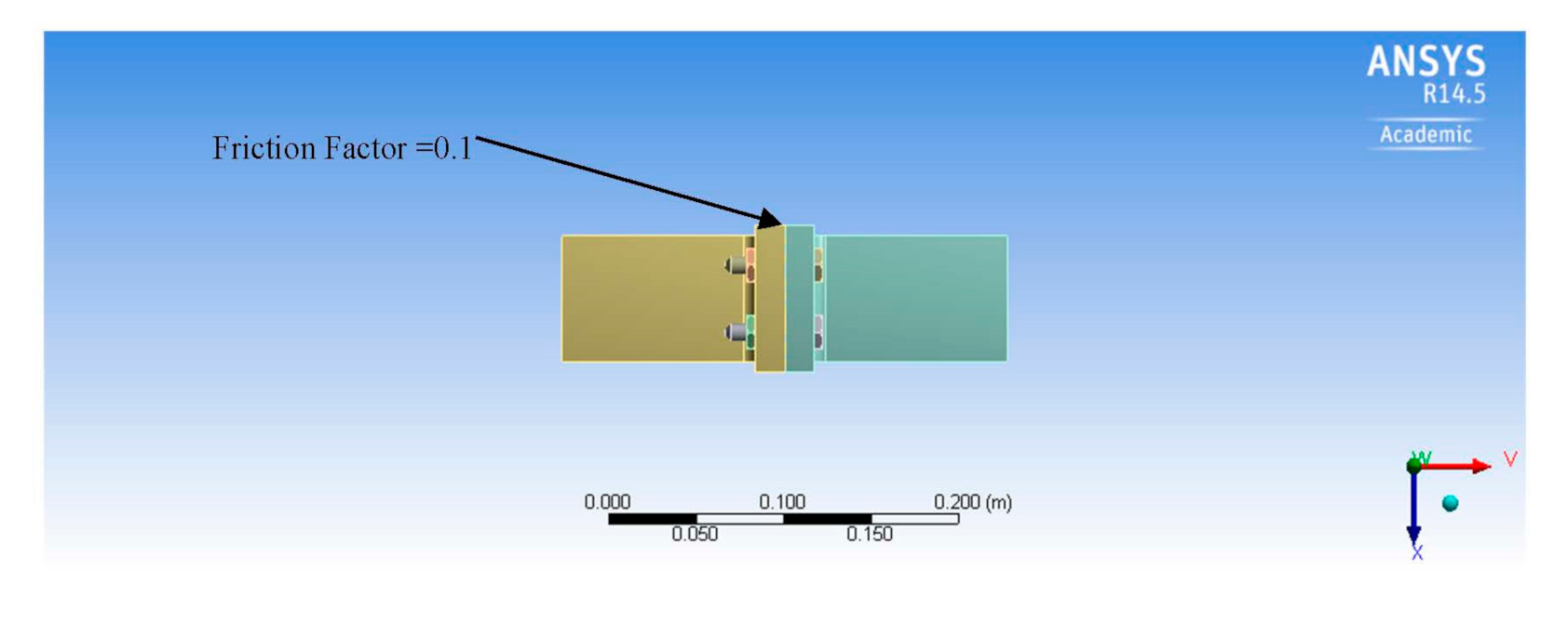
A pipe with an internal pressure of 1 MPa was used to connect the flanges. Internal pressure was used as a second load in the simulation after the application of bolt pre-tension. Figure 2 shows the development of a non-linearity problem in connected areas. A 0.1 friction factor was assigned to the area of contact between the two flanges [11]. It sat asymmetrically, meaning the contacting regions will have a single side manifestation. The flanges were clamped by tightening the bolts and nuts.
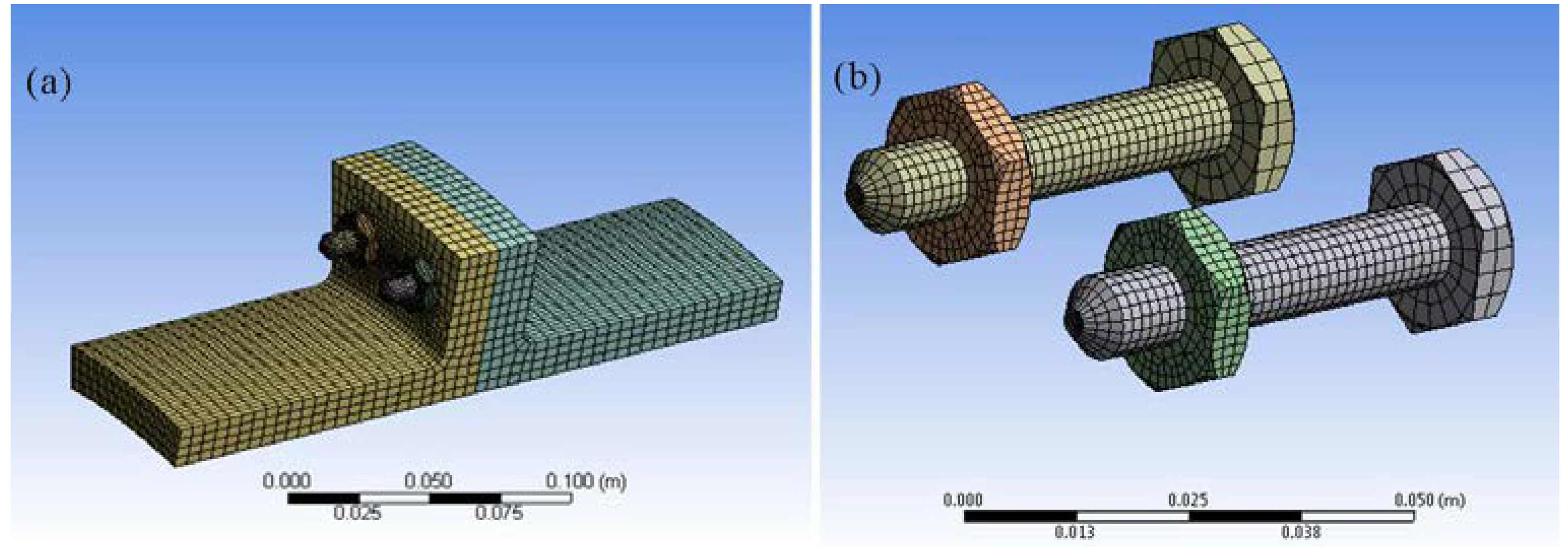
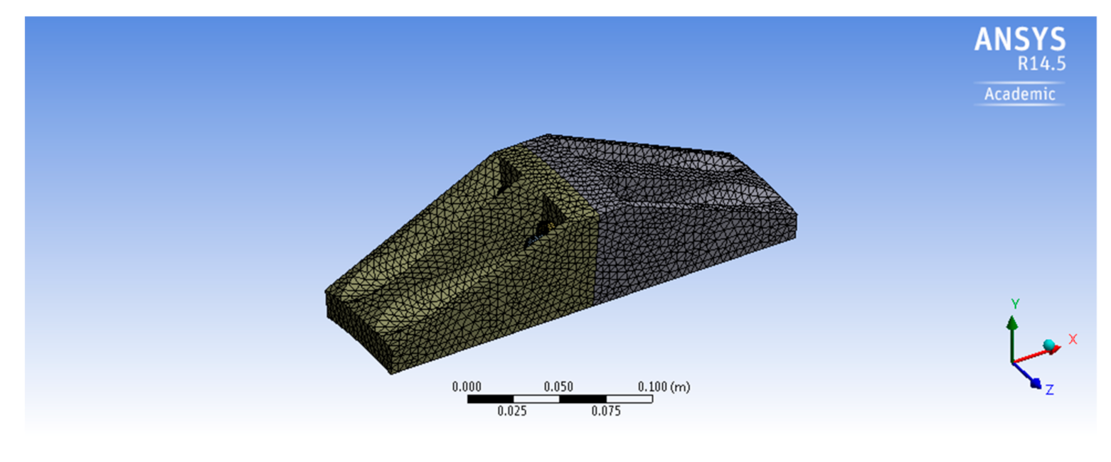
Meshing is an essential factor in modeling, with bolts being vital maximum stress areas. Figure 3 shows the mapping and meshing of geometry using a Hexahedron connection. After the experiment, the geometry was altered by making it stiffer to achieve a more complex geometry for the investigation and comparison of joint behavior; see Figure 4.
Numerical Results
The utilization of various computer-assisted engineering investigation tools was needed in the engineering examination of the bolted joint arrangement. The tools included those that represented geometry, produced the models for infinite elements, performed analysis of the structure, and those that refined the computed findings. Besides this, system response was studied through analysis to determine modeling challenges to facilitate the precise bolted joint structure simulation and to offer pre-investigation predictions, should these need to arise. Various measures such as the bolt axial load function, fixed end reaction force, separation of flanges (or lift-off), lateral joint displacement, and strains were used to characterize the joint behavior.
Ansys Workbench 14.5 was used for all the analyses. There are two primary stages involved in the investigation. First was the application of bolt preload axial force at a particular value and watch local damage and stress response. Second, internal pressure application acted on the wall of the pipe. These were non-linear analyses as a result of explicit association modeling between the surfaces of the flanges.
4. Solutions for Static Structures
Figure 5 shows the structural behavior of a preloaded bolted joint. The bolt load is a function of the applied torque. The baseline analysis has two phases. Application of (5927 lb) preload onto the modeled flanges and monitoring its behavior to the initial stress is the first phase. This tightens them in a manner that simulates how a bolted joint tightens. Simulating water through a (1 Mpa) internal pressure pipe is the second phase.
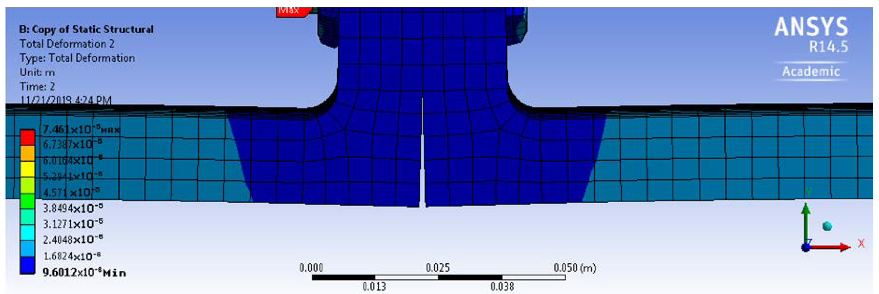
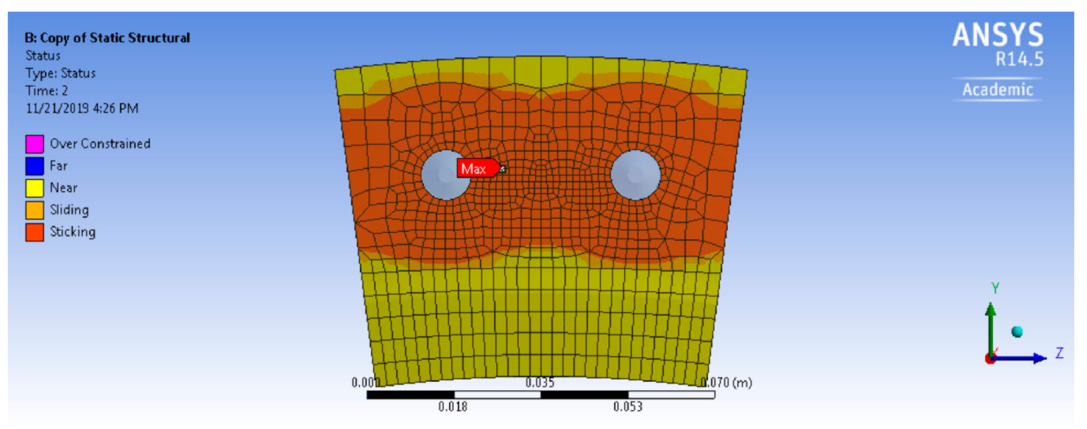
Figure 6 shows flange separation (or lift-off) based on the reaction force. There is a non-linear increase of the lift-off, and the opening of the gap nearly reaches 0.005 inches with the application of the 5927 lb load. Nevertheless, there was no total separation of the flanges. Figure 7 shows flanges gliding atop and around the bolts.
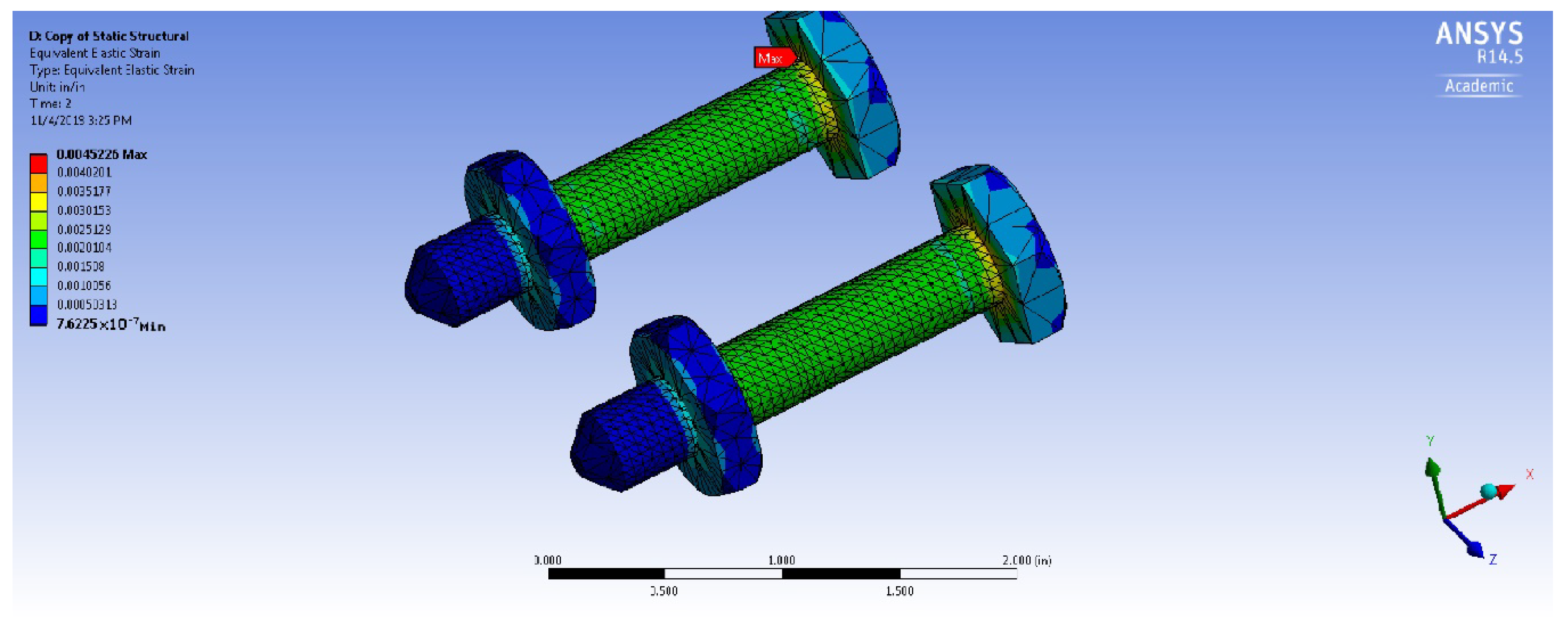
Figure 8 shows the bolt equivalent static strains. The strains originate from the center of the bolt between the head of the bolt and the nut. The average value of the strain depicts the nominal stress of the membrane. The specimen has minimal surface strain extent at the design load locations. Besides this, these strain findings reveal significant joint bending behavior at the reaction load.
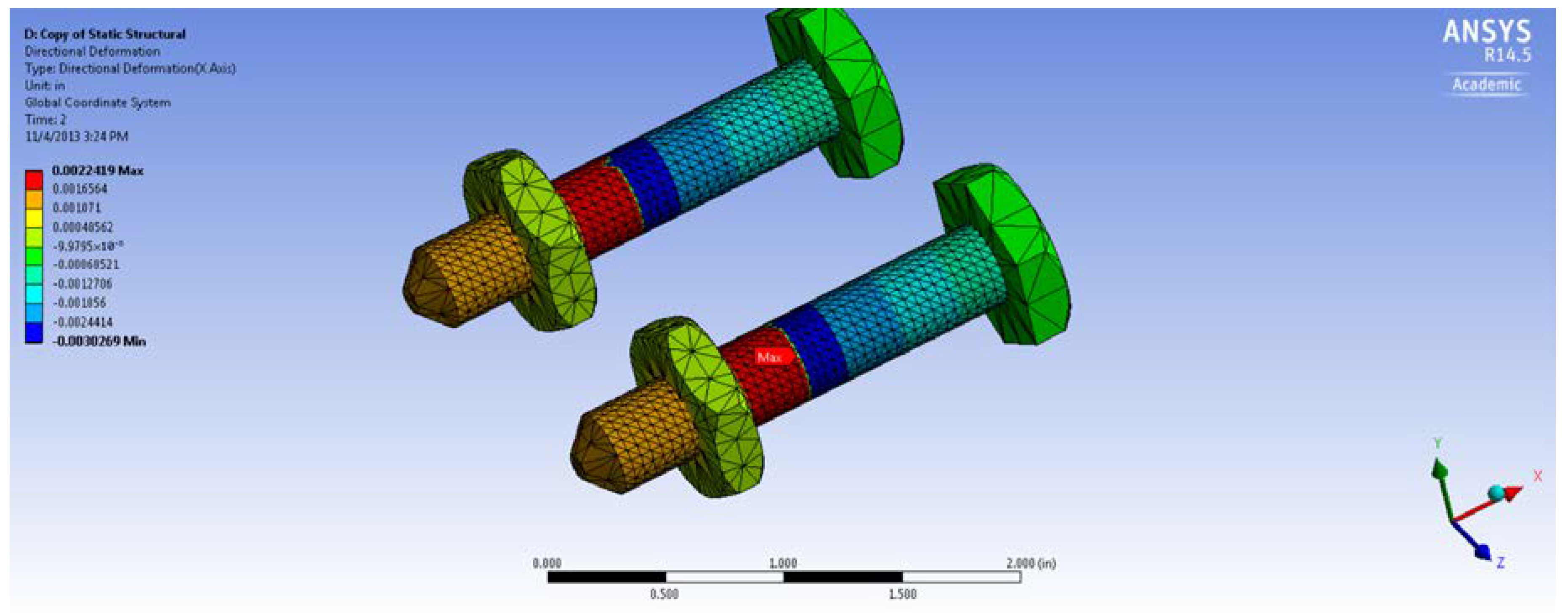
Figure 9 shows the joint’s lateral displacement. The front surface is used to measure the lateral movement at the joint interface; it is uniform across the joint width. Positive measures show a standard direction displacement of the joint to the back surface, while negative results show a standard movement of the joint to the front surface. These findings indicate an outward displacement of the bolted joints (the front face direction).
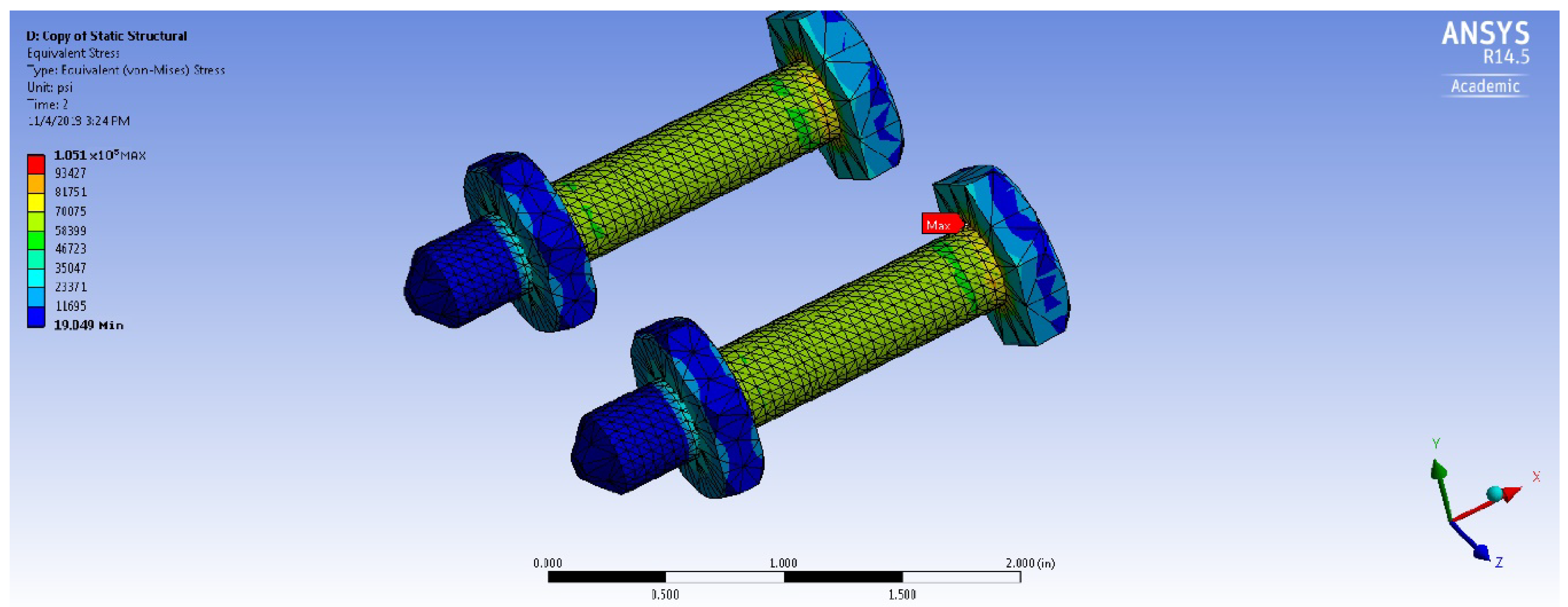
Figure 10 and Figure 11 show the axial deformation and the load von Mises stress σvm. These figures show the results for the 5927 lb load, including low von Mises levels of stress on the flanges. Many high-stress results are as a result of the flange bolts experiencing preload states. The corner of the head of the bolt also exhibits high stress as a result of the sharp model ends, which are absent in a real bolt.
These findings show that it is easy to simulate the primary structural behavior of a preloaded joint. The technique is to first evaluate the condition of the preloaded joint, then to apply the external mechanical loads. In this investigation, a uniform internal loading pressure was imposed as the external loading. Next, parametric investigations are conducted to identify the factors that have significant effects on predicting the structural behavior of the joint.
Application of simple geometry (L-shape) bolt preload torque was the first modeling hypothesis to be considered. In the model for finite analysis, the preload axial force, computed using Equation (1), was specified instead of the preload torque. Nevertheless, in an ordinary bolted joint, a torque wrench is used to measure the preload torque. The joint structural behavior is indicated based on the bolt load and the induced internal pressure but assuming a 0.2 nut factor.
Influences of Complex Geometry
Analyzing similar circumstances on a complex geometry that Figure 4 shows was the second hypothesis of modeling. It was to investigate the influence of increasing stiffness and reduce the lift-off behavior.
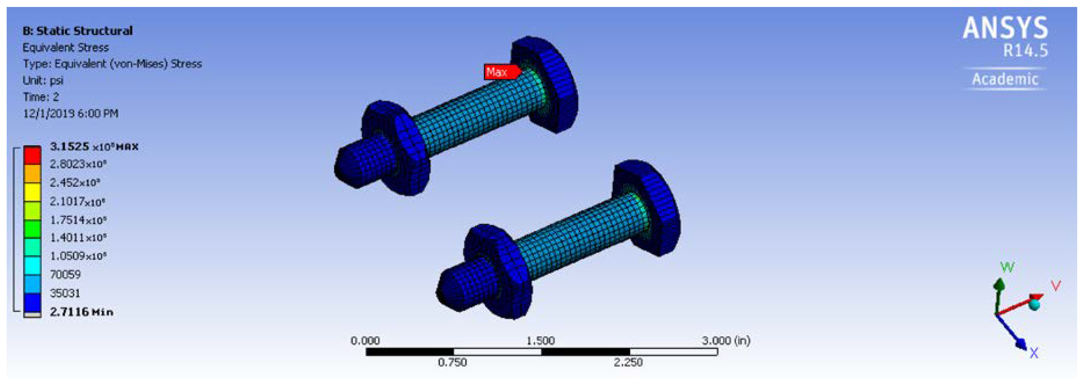
The findings show that there was an improvement in the primary structural behavior of the preloaded bolted joint. Both nut and bolt stresses were reduced; this facilitated the adjusted geometry to maintain a higher load, as shown in Figure 12. Figure 13 clearly shows that there was a reduction of the lift-off response, while the flanges stuck to each other.
5. Conclusions and Discussion
This paper explains the analysis of structural bolted joint arrangement to describe primary modeling and the requirements for investigations, and determines that the arrangement significantly influences the behavior. The Ansys Workbench 14.5 code was used to perform an elasto-plastic, large-deformation, non-linear finite element analysis. Various factor analyses were conducted, and it revealed that the bolts were the most significant factor affecting the response of the bolted joint. It was determined that modifying the flanges could diminish the response of the preloaded bolts. The parametric study results offer insights to lead future bolted flanges modeling and simulations. There are some uncertainties in the simulation of structural joint and connection behavior such as the ones in these experiment models, which can be averted by calibrating the results of this analysis with test findings.
Funding
This research received no external funding.
Conflicts of Interest
The author declares no conflict of interest.
References
- Welch, M. A Paradigm for the Analysis of Preloaded Bolted Joints. Stroj. Časopis-J. Mech. Eng. 2019, 69, 143–152. [Google Scholar] [CrossRef]
- Oldfield, M.; Ouyang, H.J.; Mottershead, J.E.; Kyprianou, A. Modelling and Simulation of Bolted Joints under Harmonic Excitation. Mater. Sci. Forum. 2003, 440–441, 421–428. [Google Scholar] [CrossRef]
- Knight, N.; Phillips, D.; Raju, I. Simulating the Structural Response of a Preloaded Bolted Joint. In Proceedings of the 49th AIAA/ASME/ASCE/AHS/ASC Structures, Structural Dynamics, and Materials Conference, Schaumburg, IL, USA, 7 April 2008. [Google Scholar]
- Thoppul, S.D.; Gibson, R.F.; Ibrahim, R.A. Phenomenological modeling and numerical simulation of relaxation in bolted composite joints. J. Compos. Mater. 2008, 42, 1709–1729. [Google Scholar] [CrossRef]
- Somasundaram, D.S.; Trabia, M.B.; O’Toole, B.J. A methodology for predicting high impact shock propagation within bolted-joint structures. Int. J. Impact Eng. 2014, 73, 30–42. [Google Scholar] [CrossRef]
- Zeng, G.Y.; Zhao, D.F. Simulation and Experiment of Dynamics of Flange Structure with Bolted Joint. Adv. Mater. Res. 2011, 335−336, 543–546. [Google Scholar] [CrossRef]
- ToolBox, E. Bolt Stretching and Tensile Stress. Available online: https://www.engineeringtoolbox.com/bolt-stretching-d_1164.html (accessed on 2 May 2020).
- Fan, H.; Malsbury, J. Handbook for Bolted Joint Design, NCSX-CRIT-BOLT-00 14 February 2007. Available online: https://ncsx.pppl.gov/NCSX_Engineering/Design_Criteria/BoltedJoint/NCSX-CRIT-BOLT-00-Signed.pdf (accessed on 3 May 2020).
- Shigley, J.E. Shigley’s Mechanical Engineering Design; Tata McGraw-Hill Education: New York, NY, USA, 2011. [Google Scholar]
- Chambers, J.A. Preloaded Joint Analysis Methodology for Space Flight Systems; NASA Technical Memorandum: Cleveland, OH, USA, 1995. [Google Scholar]
- Daniel, P.H. The Design and Fabrication of a Passive and Continuously Repositionable Joint. Ph.D. Thesis, Massachusetts Institute of Technology, Cambridge, MA, USA, 2013. [Google Scholar]
Figure 1.
Two bolts were used to simulate the preloaded bolted joint of the flange.

Figure 2.
The friction factor at the area of contact between the two flanges that develops the non-linearity problem.
Figure 2.
The friction factor at the area of contact between the two flanges that develops the non-linearity problem.

Figure 3.
Hexahedron connection was used to map and mesh the (a) the flange (b) the bolts and nuts.

Figure 4.
A complex geometry is generated to make a stiffer joint.

Figure 5.
The phases of the structural behavior of a preloaded bolted joint.

Figure 6.
The flanges separation under load.

Figure 7.
The flanges gliding atop and around the bolts.

Figure 8.
The bolt equivalent static strains as a function of the reaction load.

Figure 9.
The joint’s lateral displacement as a reaction force function.

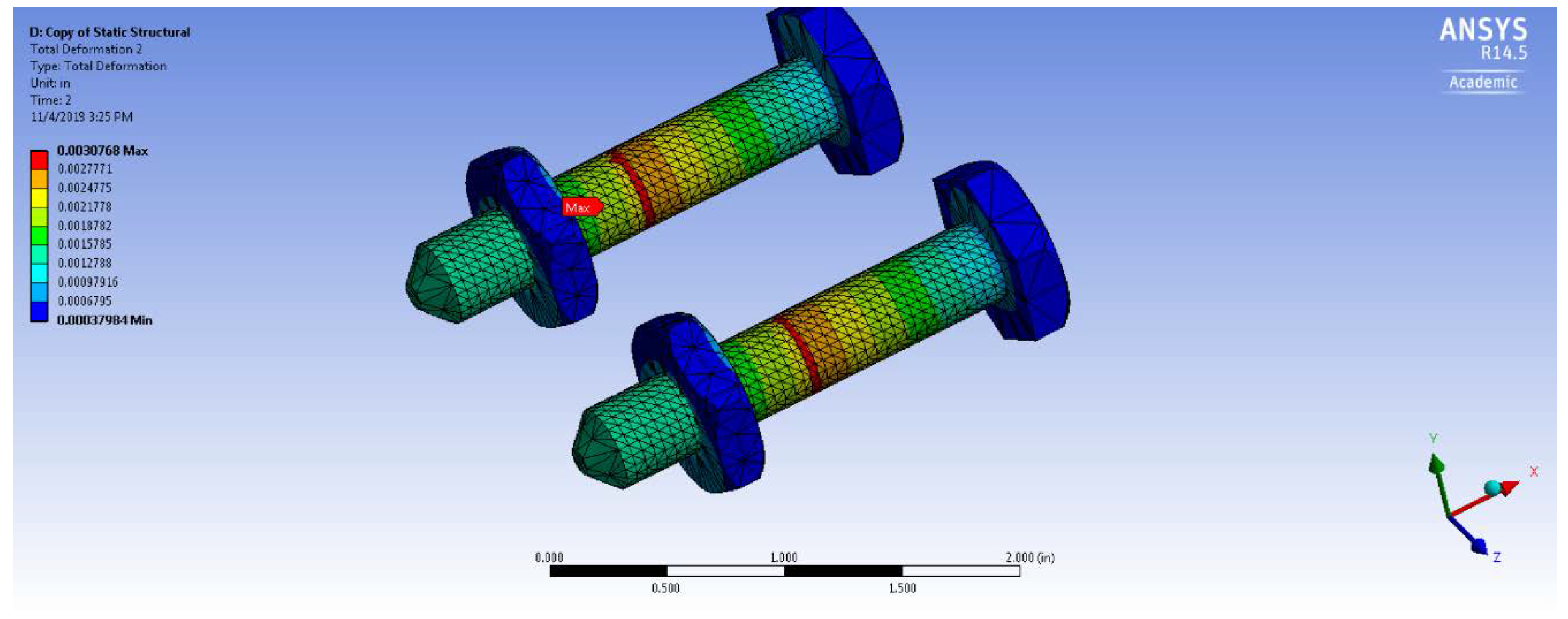
Figure 10.
The axial deformation of a preloaded bolted joint.

Figure 11.
The equivalent stress (von Mises) of a preloaded bolted joint.

Figure 12.
The equivalent stress (von Mises) of a preloaded bolted joint on the complex flanges.

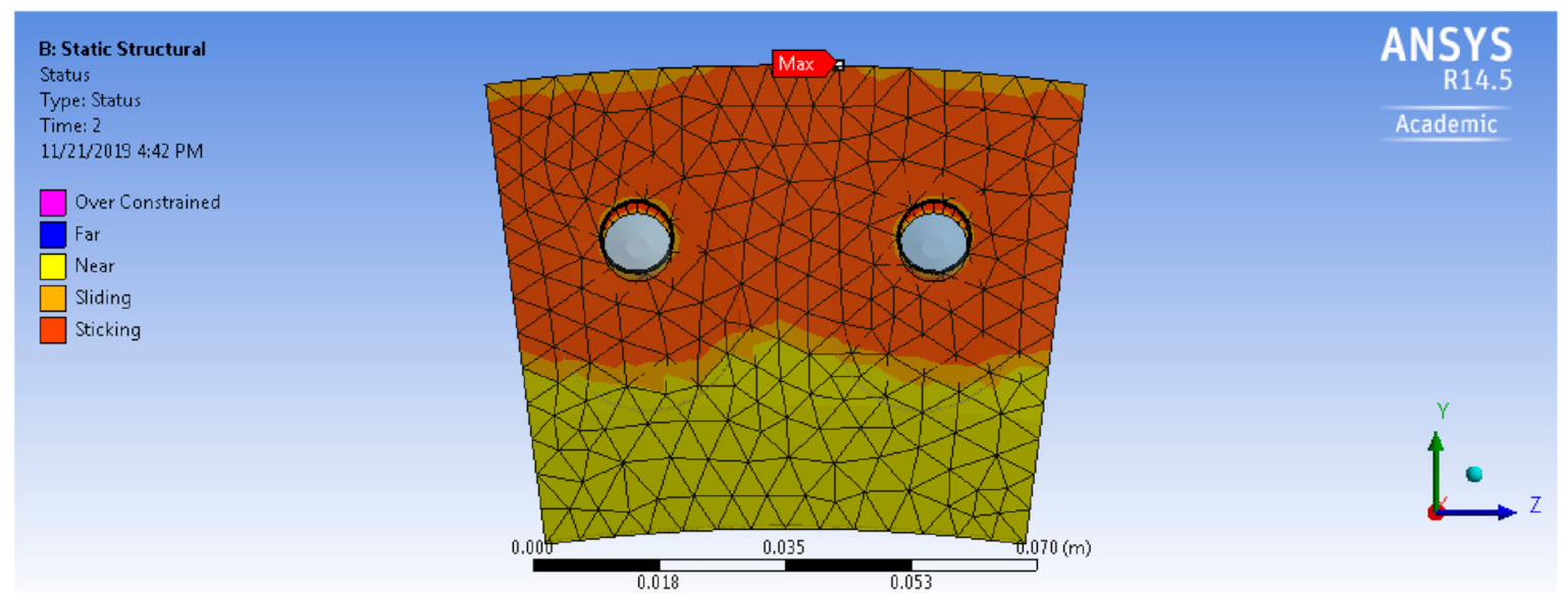
Figure 13.
The complex flanges gliding atop and around the bolts.

Publisher’s Note: MDPI stays neutral with regard to jurisdictional claims in published maps and institutional affiliations. |
© 2020 by the author. Licensee MDPI, Basel, Switzerland. This article is an open access article distributed under the terms and conditions of the Creative Commons Attribution (CC BY) license (http://creativecommons.org/licenses/by/4.0/).
Share and Cite
MDPI and ACS Style
Alfattani, R. Modeling and Simulating the Static Structural Response and Lift Off of a Preloaded Bolted Joint on a Flange. Proceedings 2020, 63, 10. https://0-doi-org.brum.beds.ac.uk/10.3390/proceedings2020063010
AMA Style
Alfattani R. Modeling and Simulating the Static Structural Response and Lift Off of a Preloaded Bolted Joint on a Flange. Proceedings. 2020; 63(1):10. https://0-doi-org.brum.beds.ac.uk/10.3390/proceedings2020063010
Chicago/Turabian StyleAlfattani, Rami. 2020. "Modeling and Simulating the Static Structural Response and Lift Off of a Preloaded Bolted Joint on a Flange" Proceedings 63, no. 1: 10. https://0-doi-org.brum.beds.ac.uk/10.3390/proceedings2020063010