Coal and Biomass Co-Combustion: CFD Prediction of Velocity Field for Multi-Channel Burner in Cement Rotary Kiln †


Faculty of Sciences of Tétouan, University Abdelmalek Essaadi, BP. 2121, Tetouan 93002, Morocco
*
Author to whom correspondence should be addressed.
†
Presented at the 14th International Conference on Interdisciplinarity in Engineering—INTER-ENG 2020, Târgu Mureș, Romania, 8–9 October 2020.
Proceedings 2020, 63(1), 18; https://0-doi-org.brum.beds.ac.uk/10.3390/proceedings2020063018
Published: 11 December 2020
(This article belongs to the Proceedings of The 14th International Conference on Interdisciplinarity in Engineering—INTER-ENG 2020)
Abstract
:This paper represents the medialization of alternative fuels co-combustion, in a cement rotary kiln, established on the commercial computational fluid dynamic (CFD) software ANSYS FLUENT. The focus is placed on the key issues in the flow field, mainly on how they are affected by turbulence models and co-processing conditions. Real data, from a Moroccan cement plant, are used for model input. The simulation results have shown a potential effect of the physics model on turbulent and gas-solid flow prediction. The CFD results can be taken as a guideline for improved co-processing burner design and reduce the effect of using alternative fuels.
1. Introduction
Alternative fuels (AF) have different chemical and physical properties compared to fossil fuels [1]. Thus, AF particles differ from coal in shape and size, their aerodynamics, and their heating up and combustion mechanism. Co-firing coal/OP (olive pomace) modeling in a cement kiln burner is an intricate process that includes gas and particle phases as well as a turbulence effect on the combustion mechanism and heat transfer.
Although much work [2,3,4,5,6] has been done on AF co-combustion, few researches on CFD (computational fluid dynamic) modeling of co-firing AF under rotary cement kiln burner conditions are available in the literature. Even though the efficiency of different K-epsilon models has been improved in recent years on predicting PF combustion, most improvements have been achieved by minimizing the calculation cost. Nonetheless, it is possible to further improve efficiency by comparing these models to choose a well-predicting model for novel alternative fuel. With this goal, this work seeks to develop a comparison between the three K-epsilon models (standard (STD), RNG (re-normalization group), and RKE (realizable K-epsilon)) combined with the eddy dissipation model, in a 2D modeling case of co-firing coal with olive pomace, under real rotary cement kiln burner conditions. The object is to explore how the flow field is affected by the turbulence models and how the co-processing environment can change the turbulence shape in the rotary kiln. The goal is to have a model that could well predict the turbulence behavior in the kiln environment, could take into account the difference in physical properties of AF versus coal, and could be able to give an overview of the kiln process parameters when changing the co-firing rate.
2. Mathematical Models
The co-combustion in rotary cement kiln burner startup by carried combustibles particles, from the pulverizer to the furnace, using pressurized air. The flow in the rotary kiln is a gas-solid turbulent flow with chemical reactions. The Eulerian-Lagrangian approach is usually used and recommended for modeling dilute gas-solid flows in pulverized fuels (PF) combustion applications. In the Eulerian-Lagrangian approach, the motion of the continuous phase is modeled using the Eulerian framework, and the motion of dispersed-phase particles is modeled using the Lagrangian framework [7]. In this work, the focus was placed on the comparison of K-epsilon model varieties coupled with turbulence-chemistry interaction model (FR/ED (finite rate/eddy dissipation), i.e., how each model impacts the flow field).
2.1. Gas-Phase Governing Equations
The time-averaged steady-state Navier–Stokes equations, as well as the mass and energy conservation equations, are solved. The governing equations for the conservations of mass, momentum, energy, and species are given as:
The source Sm in Equation (1) is the mass added to the continuous phase due to the combustion of particles. Equation (2) is the steady-state momentum equation, where P is static pressure, is the shear forces, and it is called a stress tensor. The third term on the right-hand side (RHS) represents the gravitational body force and the last term is the drag force source term. The first three terms on the RHS of the energy equation in Equation (3) represent the energy transfer due to conduction, species diffusion, and viscous dissipation, respectively. is a source term including the heat of chemical reaction and radiation. Radiation heat transfer is calculated using the P1 model, and the absorption coefficient is evaluated by the weighted sum of the gray gas model (WSGG) [8,9]. Equation (4) is the species mass fraction conservation equation for the species. is the chemical reaction production rate of species (this rate will be calculated by the FR/ED turbulence-chemistry interaction models) and is the source term added from the dispersed phase. is the turbulent diffusion flux of species [10].
2.2. Particle-Phase Governing Equations
Alternative fuels are bigger, lighter in density, and are less spherical compared to coal, which affects the motion of particles in the furnace. In the present work, for simplification, we considered AF as a spherical particle; also, the AF and coal particles were modeled separately with two discrete phases following a Rosin-Rammler size distribution [11]. The particles were tracked in Lagrangian frame reference using a stochastic model [12] as shown in Equation (5).
where is the gravitational force, and is the drag coefficient, which is an empirical function of as described by Morsi and Alexander [13]. Here is the relative Reynolds number, and it’s written as,
In this work, the combustion of solid particle conversion is treated as heating, devolatilizing, and char burning process. For computing volatilization, the single kinetic rate model [14] was used. The kinetic-diffusion limited model [15] was used for char combustion modeling. For both volatilization and char combustion, only convection and heat released by reactions were computed.
3. Numerical Computation and Strategy
3.1. Geometry and Grid Description
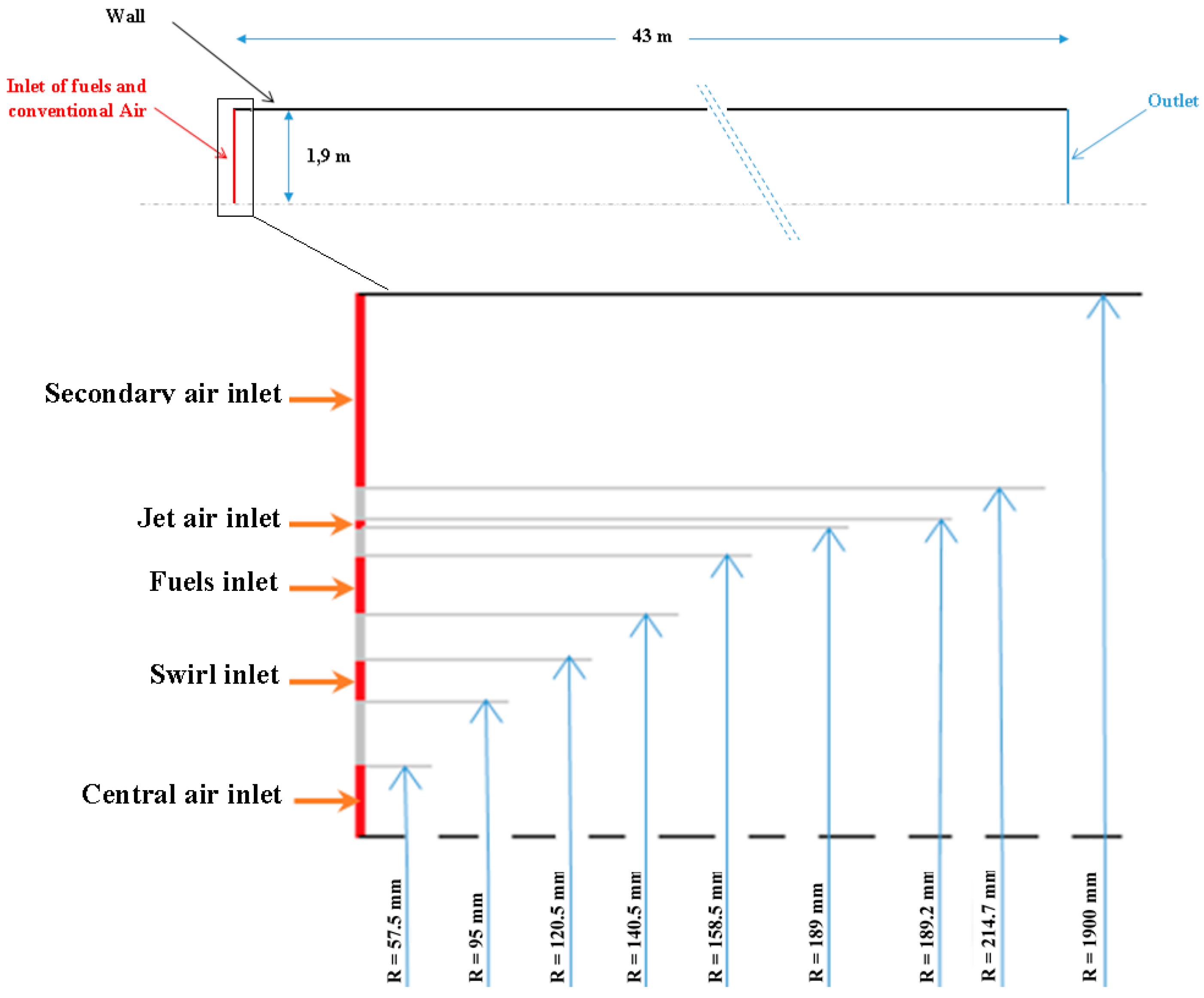
The rotary kiln used in this paper was assimilated to a real kiln with 46 m in length and 3.8 m in diameter, and it was specially equipped with a multichannel burner (see Figure 1). For simplification, the calculation was started from the fuel injection (i.e., from the burner nozzle end). Therefore, the domain of calculation considered was a 2D axisymmetric rectangle with a multi-entry for fuels and airs. Also, the burner entry geometry was modified for modeling facilities (for more details, see [16]).
Based on the geometric and calculation purposes, a structured non-uniform mesh was used, and a fine grid with 14,040 elements was selected, based on the mesh independence. To optimize convergence, the mesh had a higher density near to the burner and on the axial direction, and was coarse at the rest of the domain.
3.2. Numerical Method and Boundary Condition
The simulation of the 2D domain was implemented on the commercial CFD tool, ANSYS Fluent, based on the finite volume method. A pressure-based coupled algorithm (Coupled) was used to solve the Lagrangian-Eulerian model for gas and particle equations. To achieve numerical stability, the under-relaxation factors were carefully modified for each k-epsilon model. The limited residuals values were taken as 10−3 for continuity, 10−5 for energy and radiation, and 10−4 for all the rest of the parameters.
To be consistent with the real kiln operating condition, the inlet for temperature and velocity was similar to the real case data (see Table 1). A velocity inlet was specified at all the inlet boundaries with direction normal to boundary except for the swirl inlet that had two velocity components inlet. All the walls were treated as adiabatic and no-slip walls. The outlet was set as a pressure outlet condition. The K and epsilon inlet conditions were computed from the turbulent intensity and hydraulic diameter.
3.3. Case Study
As mentioned earlier, this paper discusses the effect of the different K-epsilon turbulence models on the velocity field prediction in a cement rotary kiln under co-combustion parameters. To this aim, six different cases were investigated and are summarized in Table 2.
4. Results and Discussion
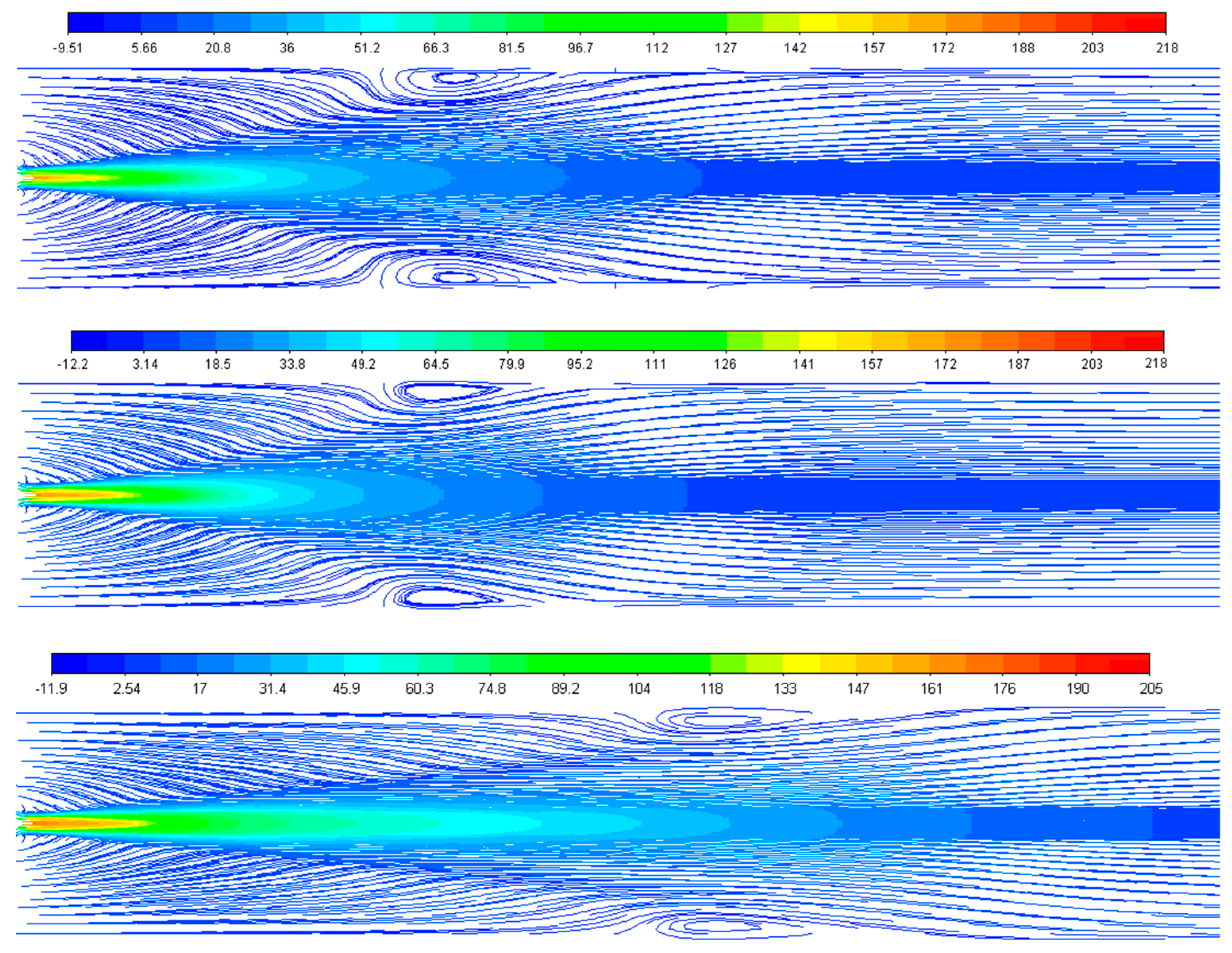
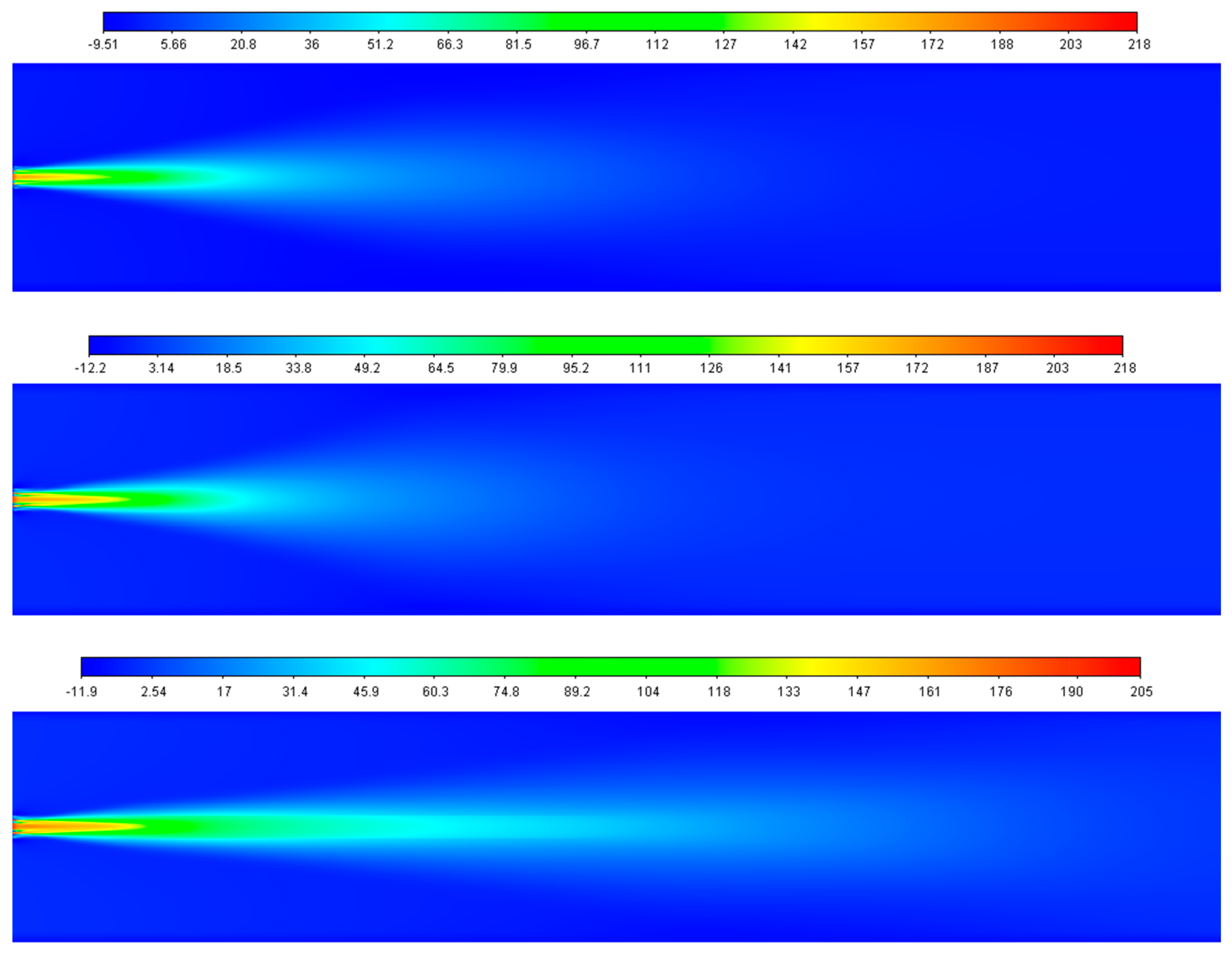
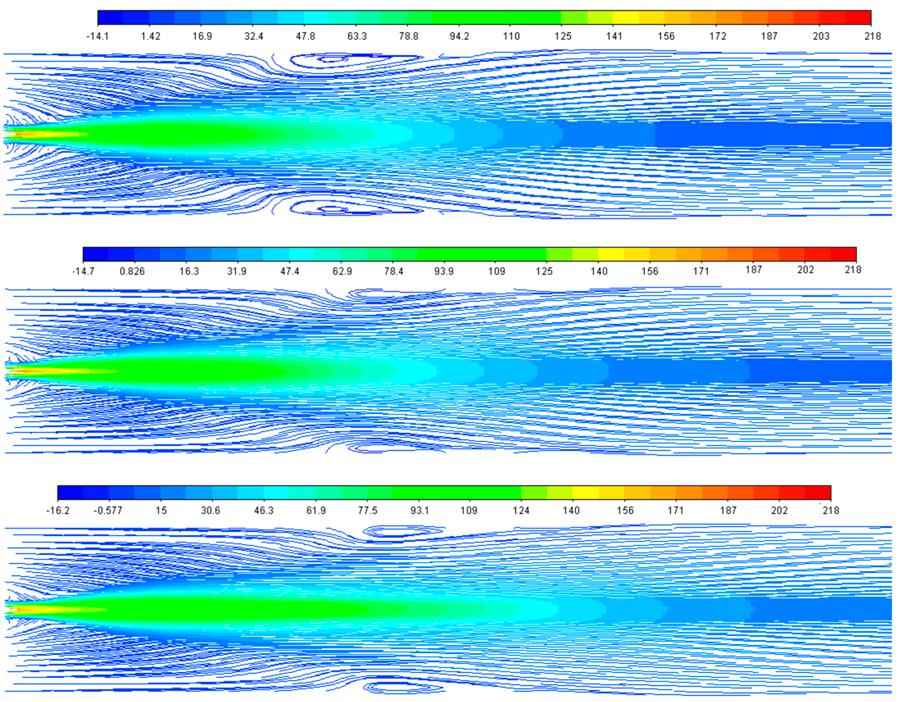
To investigate the effect of the turbulence model on the flow field, we started with an initial test without the DPM model and species reaction for the three k-epsilon models. Figure 2 shows the axial velocity streamlines without the DPM model and species reaction simulations. One can observe that the STD and RNG models predict the overall flow field similarly, however, the velocity field in RKE simulation extends further into the rotary kiln than STD and RNG, before taking a uniform distribution (see Figure 3).
The three models differ in the capture of the recirculation zone length. The RNG has a wide inner bubble recirculation zone compared to the STD and RKE at around 6.8–10.6 m. The RKE simulation gives a small inner bubble recirculation zone but a longer recirculation circle at around 9.7–14 m. The recirculation zone given by the STD is around 4.5 m. The difference comes from the epsilon equation forms and the solution method.
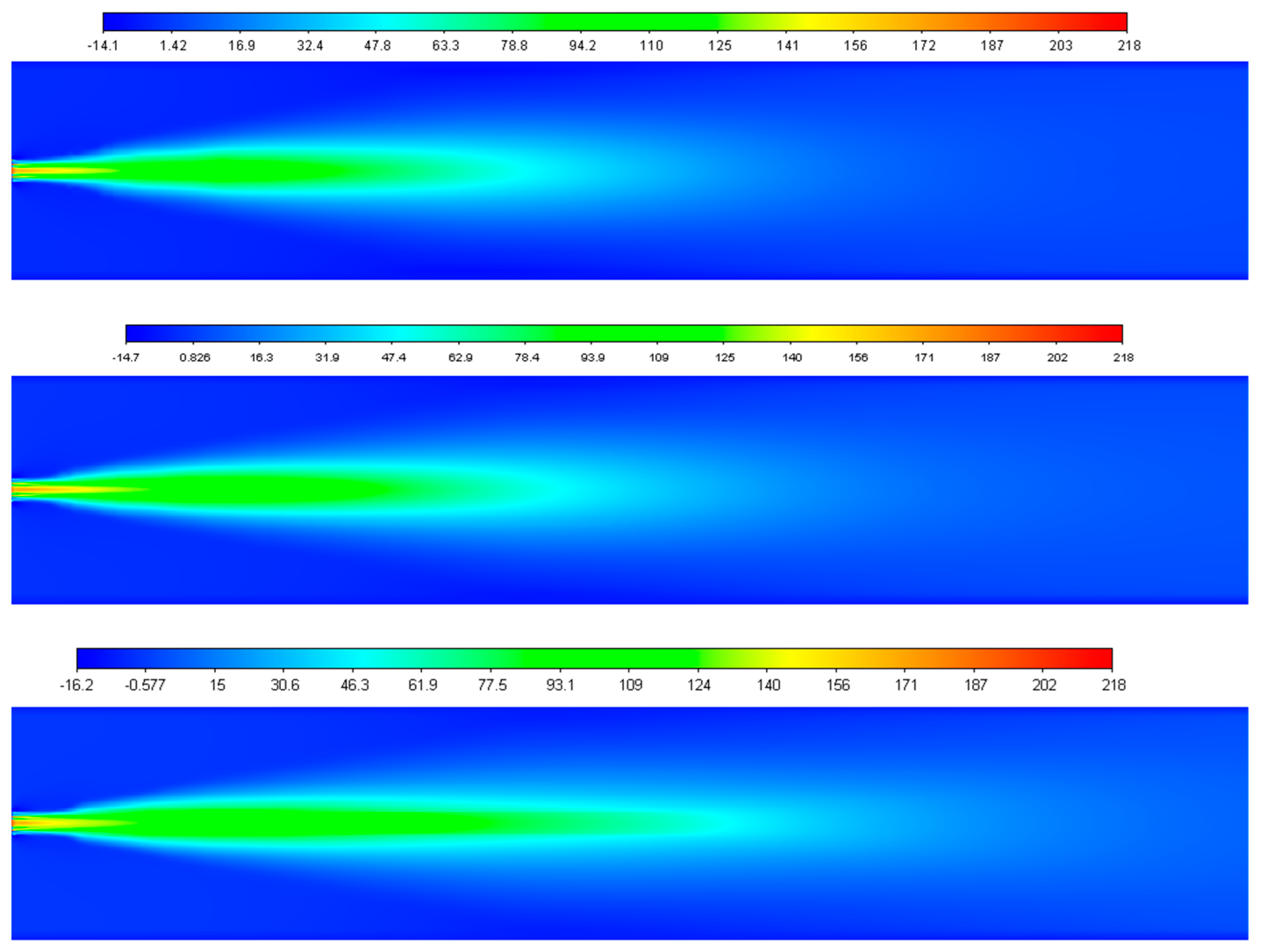
From Figure 4, for the STD and RNG cases, it can be seen that when the pulverized particles mixe into the flow, the uniform velocity field is deteriorated from 13.24 to 9.21 m/s for STD and from 10.8 to 8.58 m/s for RNG. Also, the recirculation zone is smaller than the cases without DPM as shown in Figure 5; this is due to the interaction of particle-flow.
Generally, particles interact with the flow through the drag forces and thermodynamics effect, causing a reduction in the gas turbulence and an increase in the dissipation rate of that energy which explain the decay of velocity; for more details, see [17]. For the RKE model case, we remark that the uniform velocity is higher in the case with particle injection than the DPM-off case (7.22 m/s vs. 2.54 m/s).
From the results illustrated, it is clear that the RKE model in both test cases gives the lower velocity compared to the RNG and STD models, which may be due to the dissipative nature of the RKE model. Another important point is that the STD and RNG give the lower reverse velocities, as shown in Figure 5, ensuring a speedy mixture of the hot gases with cold burner stream and the stabilization of the flame in the kiln compared to the RKE cases, which impacts the species and temperature distribution that will be discussed in another paper. Current numerical simulations of AF co-combustion are compared with the numerical results obtained by [18,19] who have investigated the simulation of oxy-coal combustion with RANS (Reynolds averaged Navier stokes) and LES (Large eddy simulation) models. The results obtained for the standard and RNG models show the same trend.
5. Conclusions
The effect of the turbulence model (i.e., STD, RNG, and RKE K-epsilon models) on the prediction of the velocity field of the real rotary kiln case was investigated.
Six different cases were simulated and predicted results were verified with available literature study. Results of the size and the position of the recirculation zone closer to the wall showed the sensitivity of the velocity field to the particle-flow interaction, especially in the RKE cases. A longer recirculation circle at around 9.7–14 m was remarked in RKE case and the recirculation zone given by the STD was around 4.5 m. Nevertheless, the STD and RNG models gave a good estimation of the flow field and recirculation zone size and length, while the RKE model performed best.
References
- Ngadi, Z.; Lahlaouti, M.L. Impact of Using Alternative Fuels on Cement Rotary Kilns: Experimental Study and Modeling. Procedia Eng. 2017, 181, 777–784. [Google Scholar] [CrossRef]
- Guessab, A.; Aris, A.; Bounif, A. Simulation of turbulent piloted methane non-premixed flame based on combination of finite-rate/eddy-dissipation model. Mechanika 2013, 19, 657–664. [Google Scholar] [CrossRef]
- Collazo, J.; Porteiro, J.; Míguez, J.L.; Granada, E.; Gómez, M.A. Numerical simulation of a small-scale biomass boiler. Energy Convers. Manag. 2012, 64, 87–96. [Google Scholar] [CrossRef]
- Yang, Y.B.; Newman, R.; Sharifi, V.; Swithenbank, J.; Ariss, J. Mathematical modelling of straw combustion in a 38 MWe power plant furnace and effect of operating conditions. Fuel 2007, 86, 129–142. [Google Scholar] [CrossRef]
- Djurović, D.; Nemoda, S.; Repić, B.; Dakić, D.; Adzić, M. Influence of biomass furnace volume change on flue gases burn out process. Renew. Energy 2015, 76, 1–6. [Google Scholar] [CrossRef]
- Tumsa, T.Z.; Chae, T.Y.; Yang, W.; Paneru, M.; Maier, J. Experimental study on combustion of torrefied palm kernel shell (PKS) in oxy-fuel environment. Int. J. Energy Res. 2019, 43, 7508–7516. [Google Scholar] [CrossRef]
- Ranade, V.V.; Gupta, D.F. Computational Modeling of Pulverized Coal Fired Boilers; CRC Press: Boca Raton, FL, USA, 2015; ISBN 9781482215359. [Google Scholar]
- ANSYS Fluent theory guide. In ANSYS Fluent Theory Guide 15.0; Ansys Inc.: Canonsbourg, PA, USA, 2013; p. 193.
- Cassol, F.; Brittes, R.; França, F.H.R.; Ezekoye, O.A. Application of the weighted-sum-of-gray-gases model for media composed of arbitrary concentrations of H2O, CO2 and soot. Int. J. Heat Mass Transf. 2014, 79, 796–806. [Google Scholar] [CrossRef]
- Spalding, D.B. Mixing and chemical reaction in steady confined turbulent flames. Symp. (Int.) Combust. 1971, 13, 649–657. [Google Scholar] [CrossRef]
- Rosin, P.; Rammler, E. The laws governing the fineness of powdered coal. J. Inst. Fuel 1933, 7, 29–36. [Google Scholar]
- Shuen, J.-S.; Chen, L.-D.; Faeth, G.M. Evaluation of a stochastic model of particle dispersion in a turbulent round jet. AIChE J. 1983, 29, 167–170. [Google Scholar] [CrossRef]
- Morsi, S.A.; Alexander, A.J. An investigation of particle trajectories in two-phase flow systems. J. Fluid Mech. 1972, 55, 193. [Google Scholar] [CrossRef]
- Badzioch, S.; Hawksley, P.G.W. Kinetics of Thermal Decomposition of Pulverized Coal Particles. Ind. Eng. Chem. Process Des. Dev. 1970, 9, 521–530. [Google Scholar] [CrossRef]
- Baum, M.M.; Street, P.J. Predicting the Combustion Behaviour of Coal Particles. Combust. Sci. Technol. 1971, 3, 231–243. [Google Scholar] [CrossRef]
- Hiromi Ariyaratne, W.K.W.K.; Malagalage, A.; Melaaen, M.C.; André Tokheim, L. CFD Modeling of Meat and Bone Meal Combustion in a Rotary Cement Kiln. Int. J. Model. Optim. 2014, 4, 263–272. [Google Scholar] [CrossRef]
- Vaillancourt, P.A.; Yau, M.K. Review of Particle–Turbulence Interactions and Consequences for Cloud Physics. Bull. Am. Meteorol. Soc. 2000, 81, 285–298. [Google Scholar] [CrossRef]
- Yilmaz, H.; Cam, O.; Tangoz, S.; Yilmaz, I. Effect of different turbulence models on combustion and emission characteristics of hydrogen/air flames. Int. J. Hydrogen Energy 2017, 42, 25744–25755. [Google Scholar] [CrossRef]
- Chen, L.; Yong, S.Z.; Ghoniem, A.F. Oxy-fuel combustion of pulverized coal: Characterization, fundamentals, stabilization and CFD modeling. Prog. Energy Combust. Sci. 2012, 38, 156–214. [Google Scholar] [CrossRef]
Figure 1.
Scheme of the 2D axisymmetric geometry and the simplified burner details.

Figure 2.
Streamlines of axial velocity without DPM (STD, RNG, and RKE respectively from the top).

Figure 3.
Axial velocity contours without DPM (STD, RNG, and RKE respectively from the top).

Figure 4.
Axial velocity contour with particle injection (STD, RNG, and RKE respectively from the top).
Figure 4.
Axial velocity contour with particle injection (STD, RNG, and RKE respectively from the top).

Figure 5.
Streamlines of axial velocity with particle injection (STD, RNG, and RKE respectively from the top).
Figure 5.
Streamlines of axial velocity with particle injection (STD, RNG, and RKE respectively from the top).


Table 1.
Operating condition data.
| Boundaries | Velocity m/s | Temperature °K |
|---|---|---|
| Secondary air inlet | 5 | 1126 |
| Jet air inlet | 218 | 500 |
| Fuels inlet | Transport air 30 Coal and AF 30 | 500 |
| Swirl inlet | Axial 212 Tangential 45 | 500 |
| Central air inlet | 200 | 500 |
Table 2.
Investigated cases details.
| Case | Turbulence Model | Turbulence Chemistry Interaction Model | Discrete Phase Model (DPM) |
|---|---|---|---|
| 1 | STD | OFF | OFF |
| 2 | ON | ON | |
| 3 | RNG | OFF | OFF |
| 4 | ON | ON | |
| 5 | RKE | OFF | OFF |
| 6 | ON | ON |
Publisher’s Note: MDPI stays neutral with regard to jurisdictional claims in published maps and institutional affiliations. |
© 2020 by the authors. Licensee MDPI, Basel, Switzerland. This article is an open access article distributed under the terms and conditions of the Creative Commons Attribution (CC BY) license (http://creativecommons.org/licenses/by/4.0/).
Share and Cite
MDPI and ACS Style
Ngadi, Z.; Lahlaouti, M.L. Coal and Biomass Co-Combustion: CFD Prediction of Velocity Field for Multi-Channel Burner in Cement Rotary Kiln. Proceedings 2020, 63, 18. https://0-doi-org.brum.beds.ac.uk/10.3390/proceedings2020063018
AMA Style
Ngadi Z, Lahlaouti ML. Coal and Biomass Co-Combustion: CFD Prediction of Velocity Field for Multi-Channel Burner in Cement Rotary Kiln. Proceedings. 2020; 63(1):18. https://0-doi-org.brum.beds.ac.uk/10.3390/proceedings2020063018
Chicago/Turabian StyleNgadi, Zakia, and Mohamed Lhassan Lahlaouti. 2020. "Coal and Biomass Co-Combustion: CFD Prediction of Velocity Field for Multi-Channel Burner in Cement Rotary Kiln" Proceedings 63, no. 1: 18. https://0-doi-org.brum.beds.ac.uk/10.3390/proceedings2020063018