Innovation of Pull and Torque Testing Device for Cable Cords †

Faculty of Engineering and Information Technology, “George Emil Palade ” University of Medicine, Pharmacy, Science, and Technology of Targu Mures, Nicolae Iorga street, No. 1, RO-540088 Targu Mures, Romania
†
Presented at the 14th International Conference on Interdisciplinarity in Engineering—INTER-ENG 2020, Târgu Mureș, Romania, 8–9 October 2020.
Proceedings 2020, 63(1), 28; https://0-doi-org.brum.beds.ac.uk/10.3390/proceedings2020063028
Published: 11 December 2020
(This article belongs to the Proceedings of The 14th International Conference on Interdisciplinarity in Engineering—INTER-ENG 2020)
Abstract
:The paper presents in the first part a diagnosis of the frequency per year of the pull and torque test followed by an analysis of the average time given to each attempt, a comparison of the average time spent on the torqueing and pulling test and the average times to perform the other tests. In the second part there is a forecast of the times spent performing the test following the optimization. The optimization is performed in the first phase at project level in the Inventor Professional 2018 program. The testing method is not foreign to companies that produce cable cord, and is it described in at least two standards. The latest developments in the electronics field show an optimization on two separate devices for each stress, pull and torque. The goal of this paper is to present an optimization of the device for pull stress testing, in order to proceed with both of the stresses on one device. The optimization aims to reduce the time spent by the quality tester in the metrological laboratory on this test. Following the optimization, in the forecast it was found that the quality of work was improved by reducing working hours and removing human assistance as much as possible in order to eliminate the errors caused by it.
1. Introduction
In modern industry, any company producing electrical cables must set its quality goals as paramount in order to remain a market leader [1]. In order to maintain its place on the market, the company must ensure the quality [2] of the products with a set of qualitative tests performed in the metrological laboratory. The tests must have a large scale to cover any possibility of premature failure and to ensure the efficiency of the product. Real attention should be paid to the potential for fires caused by wiring and its characteristics [3,4], and thermal aging [5], which reduces the safety of the electrical system [6].
One goal is the policy of continuous improvement [7], which aims to optimize the process, innovation, research and development as well as optimize working hours in the production process.
Optimization of the device aims to facilitate the work of the quality team in the metrological laboratory and to reduce the time used normally for this kind of test.
2. Innovation Need
Several analyses were carried out by the company in order to have a view of the entire time spent on the test in the metrological laboratory.
The method [8] helped to confirm the integrity of the product in the following four cases of application:
- Stumbling on the cord cable when the socket is positioned at the bottom of the wall. For example, the cord is attached to a vacuum cleaner and the user moves the appliance, creating a tension of the cable through which it no longer sits on the floor but will be taut above the floor.
- Pulling the product from its cable, in cases where the user tries to unplug the appliance by pulling directly on the appliance or pulling on the cable, instead of unplugging it by the plug.
- Transporting or lifting the product by its cable. If the appliance is small, this includes appliances weighing 1 kg or less, such as hair dryers or curlers.
- Attempting to move a product that is still electrically connected in cases where an appliance such as a vacuum cleaner is pulled from the cable.
The cables tested were the usual types, for daily use in house appliances.
The research was based on diagnosing the current condition of the cord to determine the level at which it operates. The diagnosis was based on three major points: (1) determination of the place of the test in relation to the other test performed in the laboratory, (2) determination of the average time spent on each test, and (3) determination of the time spent on the pull and torque test.
2.1. Frequency of The Test
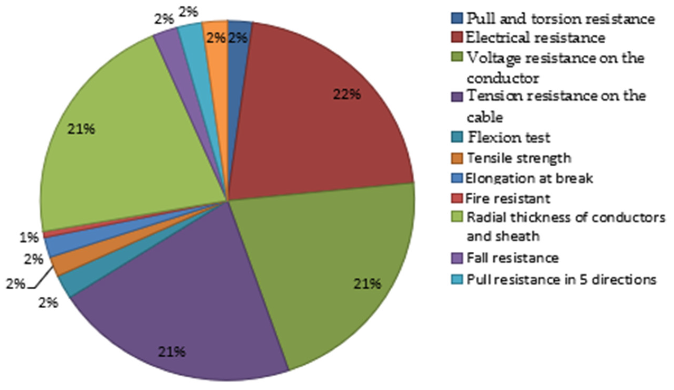
Determination of the annual number of tests was made in order to ascertain its position in relation to the other tests performed in the metrology laboratory. In Figure 1 shows all the tests performed in the laboratory and their frequency during 2019.
The diagram shows that routine or sample tests were performed at a higher frequency, routine tests being performed in the continuous flow of production and sample tests being performed on each sample to ensure product compliance. Type tests are tests that are performed on the product before delivery to ensure that the product is consistent with the requirements.
The pull and torque test is a type test performed at a frequency of 2% in a year; compared to the other tests performed, it had a much lower rate, but considering the time spent on this operation, it took longer than the sample ones. The sample test had a 21–22% rate, which was 118 times, compared to 12 times for the pull and torque test.
2.2. Time Spent on Each Test
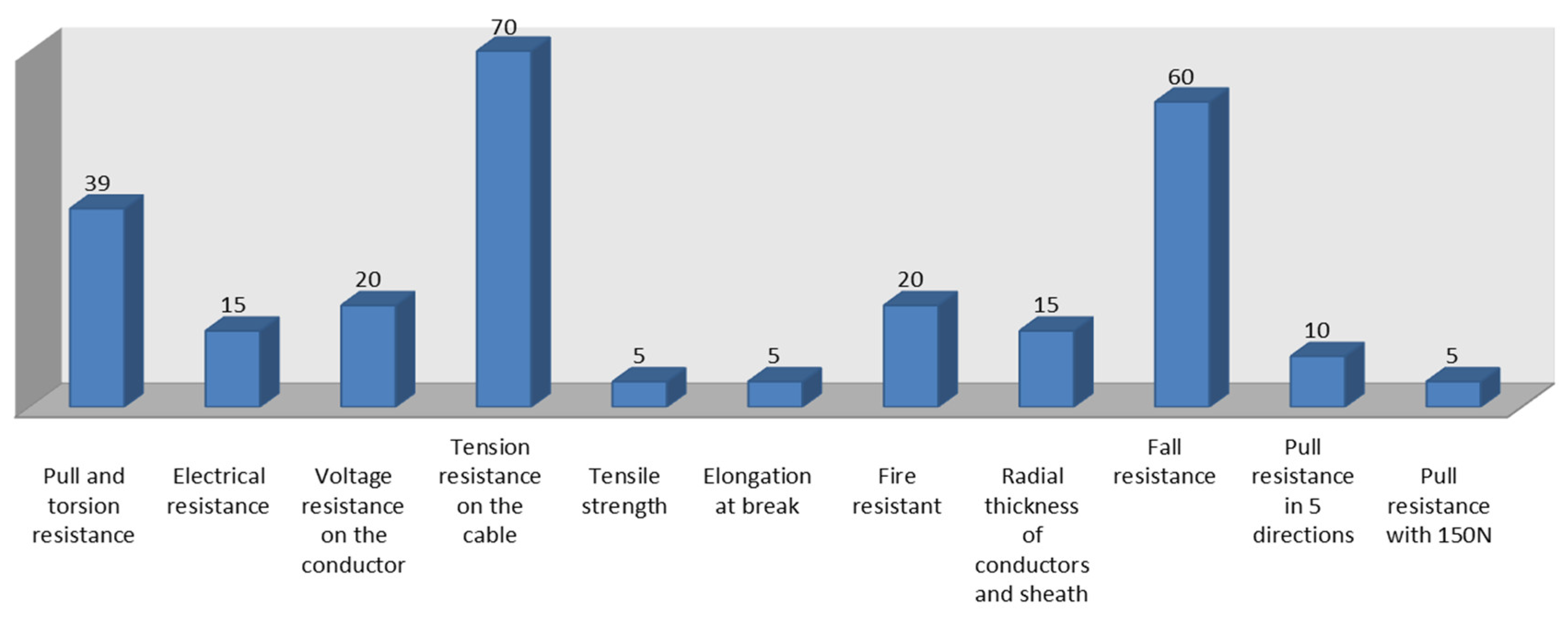
When analyzing the average time of testing it was observed that the most time spent by the operator was on the test to determine the resistance to voltage in the cable and the resistance to falling (Figure 2). For the pull and torque test, the laboratory technician spent 39 min to determine the conformity of the product.
Compared to other tests that were performed in the laboratory, this test required twice as much time as the electrical resistance, which was determined to be 15 min.
Routine or sample tests had a higher frequency but were performed in less time than the pull and torque tests; this was mainly due to the large number of operations involved in this test.
2.3. Average Time Provided for the Method
The relatively long time for the method was due to the two stresses to which the cord was subjected, the tensile stress and the torsional stress.
In this case the electrical resistance was determined as 15 min, the total time calculated for all operations taking place for this test.
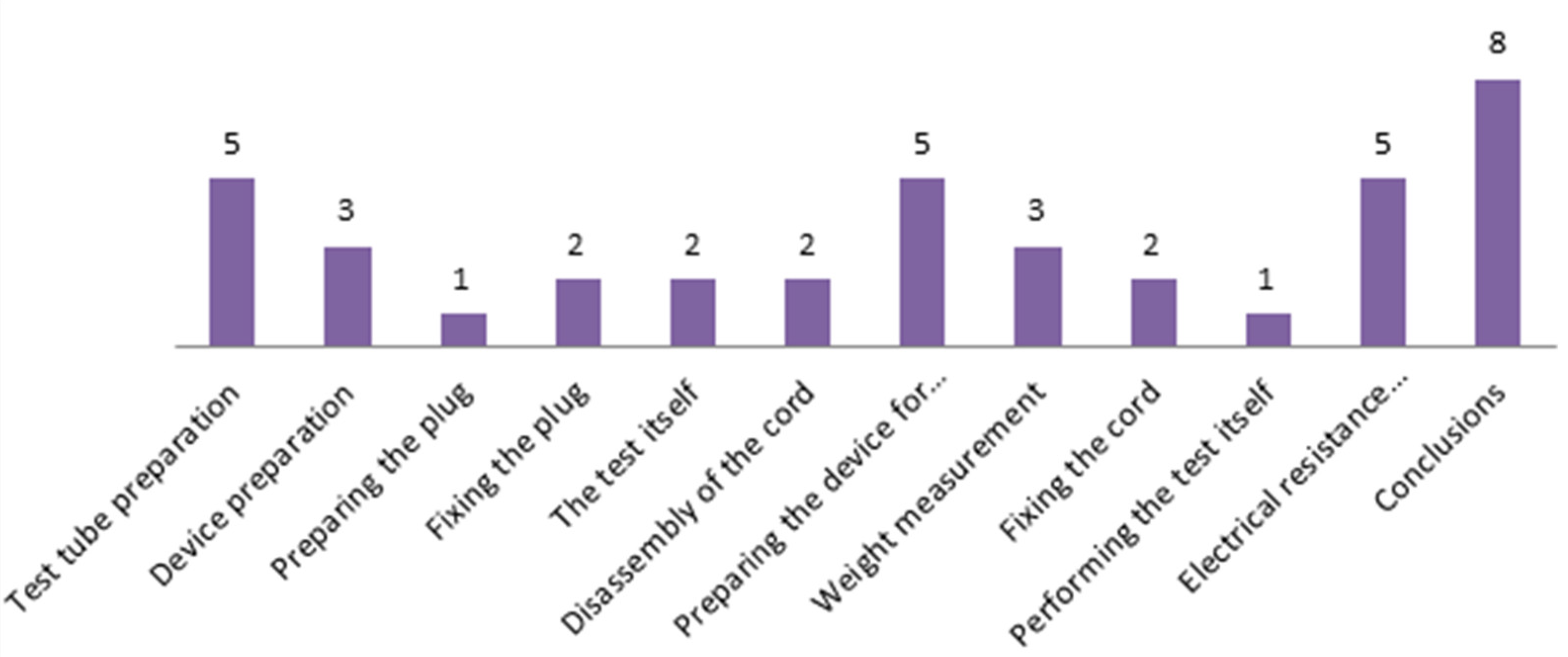
In cases of determining the conformity of the cords in the test for pull and torsion, the average time of performance was divided by all the operations that took place, as we see in Figure 3. The preparation of the test piece, which consists in cutting it to size, stripping the jacket about 10 cm, stripping the conductors about 1.5 cm, and automatically measuring the electrical resistance, was carried out in an average time of 5 min. Preparing the device, which consists of measuring the weight required to perform the test using the scale, took an average of 3 min. Preparing the plug, which consists in marking it in order to have a comparison at the end of the tests, had a duration of 1 min. Preparing the device for the torsion test had a duration of 5 min, which consists in positioning in the vise. The weight measurement, which has to be accurate, was made in 3 min. Fixing the cord took place in 2 min, and the test itself lasted for 1 min. The electrical resistance has an important value because it shows the integrity of the plug within.
3. Optimization of the Device in Inventor Professional 2018
The latest developments in this field show that there are a series of electronic devices that can perform this test separately, which means that there is one device for the pull test and another one for the torque test, although between the two devices the most important role is played by the weight because it sets the hardness of the test. Researching the international market for the types of equipment used for this kind of test, there are limited options [9,10,11,12].
Optimization of the device has the goal to facilitate the work of the quality team in the metrological laboratory and to reduce the time used normally for this kind of test.
3.1. Innovation of the Device
The version of the device that was used in the laboratory had manual actuation, which means that the 100 cycles were done by the staff manually, and the device for the torque test was separate from the device for the pull test. The staff had to walk every time from one operation desk to another, which was unnecessary time and could be reduced by an innovation of the device, so it could do both of the tests on one device.
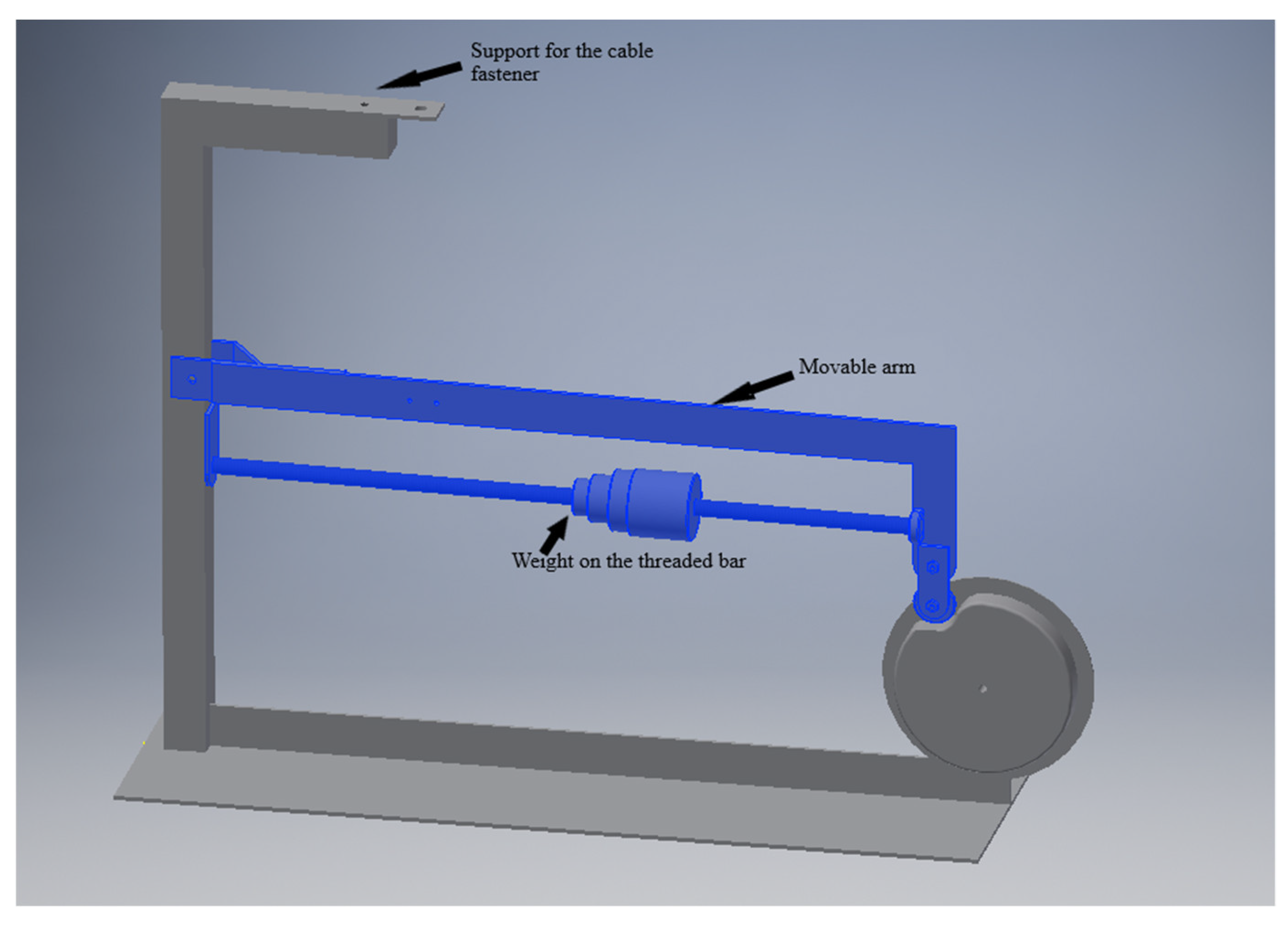
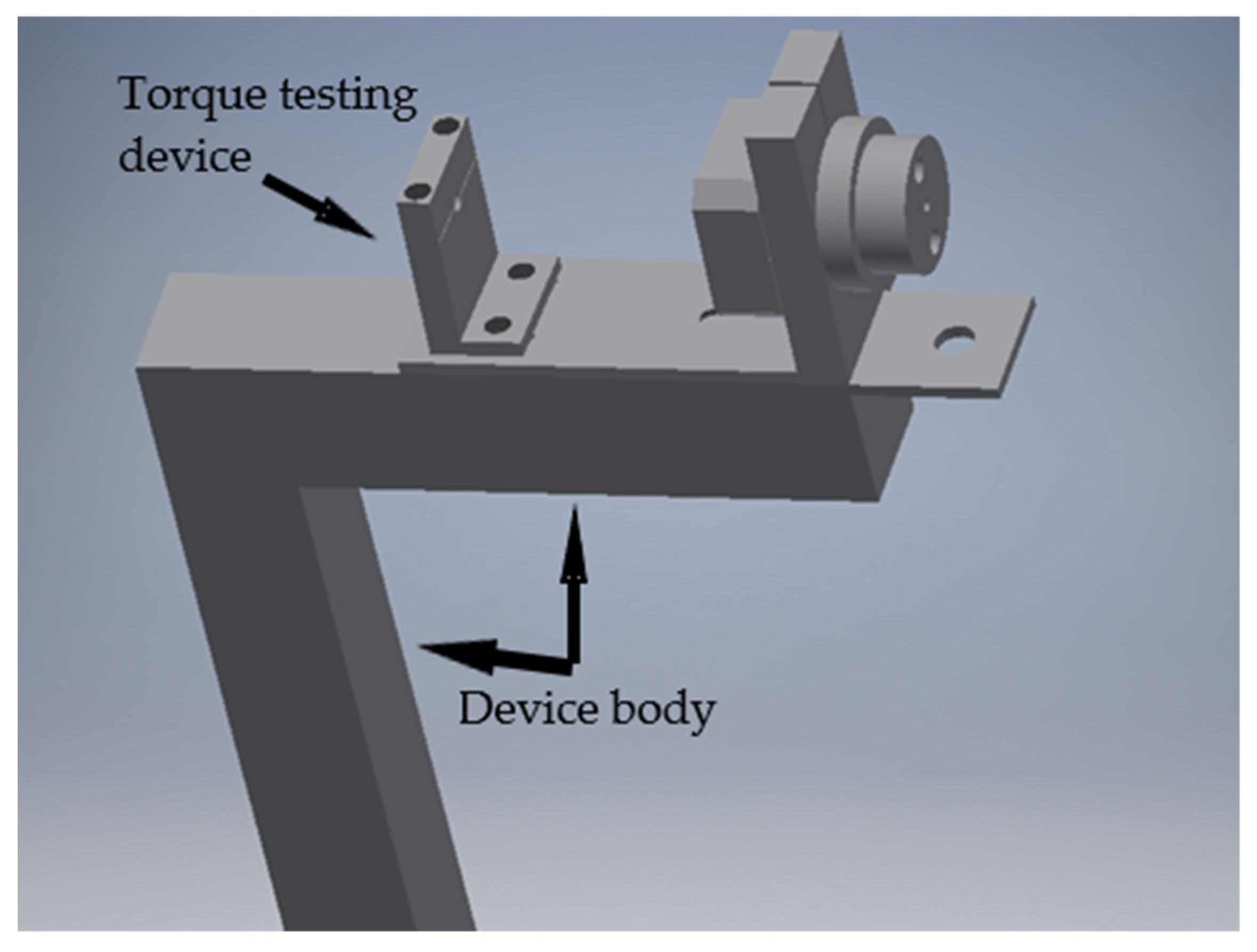
Several measurements were carried out because the weight that rolls on the filleted bar could not roll to the minimal point, tangent to the body of the device, because of the fixing device for the cable. In order for the weight to roll and make a complete cycle, the bar that holds the weight was moved below, as Figure 4 shows. The prototype for this device was made in the Inventor Professional 2018 program.
The basis of innovation was considered to be the last level at which the optimized product was located. Taking into account the latest research in this field, two separate, automated devices were used for that test.
The principle of use of the torsion device, following the innovation, changed completely. Despite the fact that the principle of operation remained identical to the previous one, the emphasis was on facilitating and excluding possible human errors that may occur as a result of the empirical use of the device.
The optimization of the device consisted in remodeling it so that both tearing and twisting requests could be executed on the same device. Taking into account the fact that a force of 100 N was applied in the pull-out test, which transformed into a unit of weight was 10,197 kg, and to the torsion test a force of 12.5 N was applied, which, transformed, was 1275 kg, it was necessary to be able to slide the weight so that the margin of force on the glazing bar passed through the cable clamp.
For the tensile stress, the device was subjected to the optimization of the movable arm for the application of the weight; the position of the weight, as can be seen in Figure 4, was changed by placing the threaded bar at the bottom of it. At the top, the support for the cable fastener was kept, the initial bar being fixed by the support rods at the bottom.
For the pull-out and torsion test device, the force arm is of major importance because its optimization in terms of achieving a torque of less than 3 kg at the moment of force creates the possibility of using the weight for both tests. This optimization can be achieved only by constructing the arm so that the weight can slide over the entire arm to make a full stroke, but once it reaches the turning point its value is equal to 0.
Mathematically, the value of the moment of force is equal to the product of the value of the force arm and the value of the force [13].
M = b × F N/m.
In relation to the moment of force, the force is directly proportional to the force arm, so as the weight slides toward the fixing point, it decreases and the force arm will also decrease.
For torsional stress, the device used was remodeled and optimized so that it could be joined and fitted to the pull stress device. The questions underlying the determination of the appropriate location were closely related to the position of the cable fastener where the weight value is measured.
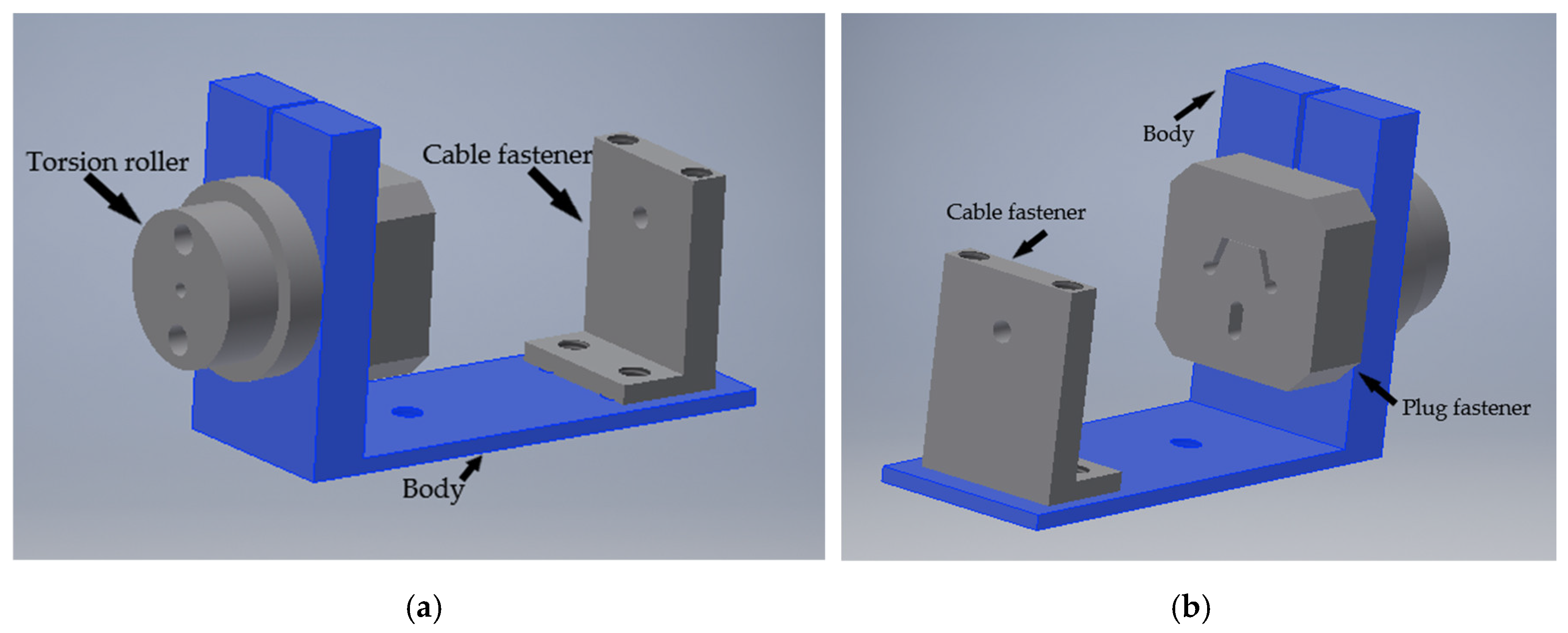
The optimized device for the torque test is presented in Figure 5, from front and rear view. The location in the upper part of the body allowed easy access to the cable entry hole for tensile stress and torsional stress when inserting the cord for the use of the same weight.
Compared to the original device, the optimized one, which is shown in Figure 6, was changed by moving the position of the cord fixing support, which was made for clamping, to the side of the device. To fix the cord in the initial device, a mobile fastening system was used that slid on the support but was fixed by screws, which in this phase is no longer possible, so the fixation was placed directly on the body of the traction device, and it will no longer be necessary to remove the traction device.
The cord that is attached to the torsion roller, and with which the device will be operated, will pass through the hole on the body of the device. The cord is fastened to the cable clamp used for the tensile stress.
3.2. Tests on the Device
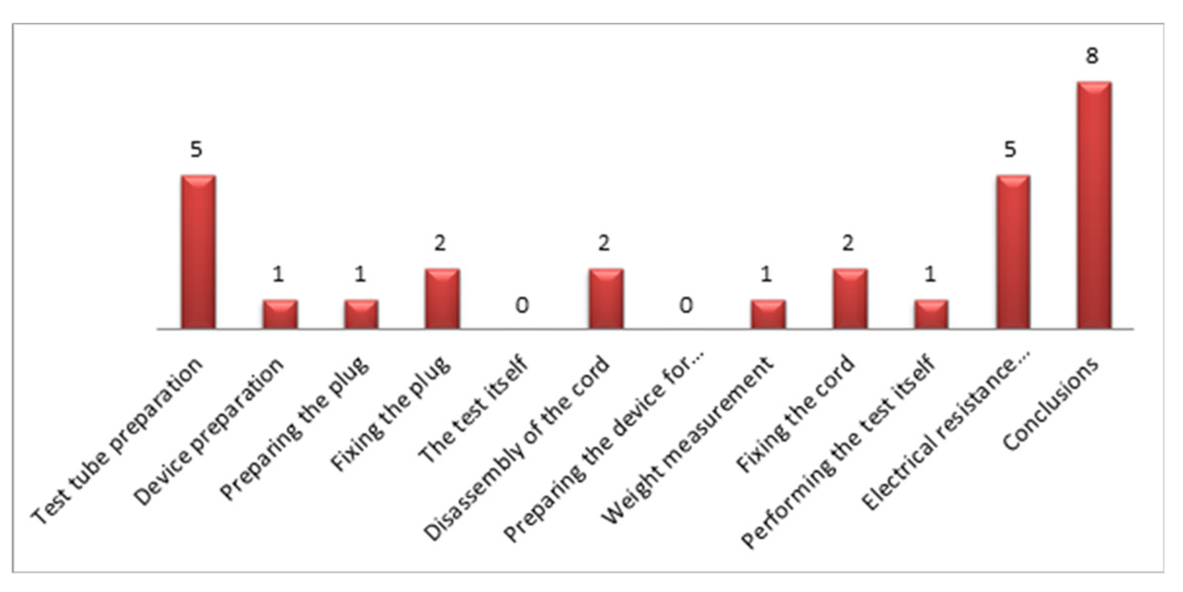
The first tests on the new device took place in May and were recorded in metrological bulletins. Following the implementation, 12 trials were performed to establish the effectiveness of the optimization. As can be seen in Figure 7, in the determination of the conformity of the cords in the tensile and torsional test on the optimized device, the average performance time was divided for all operations taking place, the preparation of the specimen and the electrical resistance were performed in the same time, an average of 5 min.
The preparation of the device, which consisted in placing the weight necessary to carry out the test on the threaded bar next to the marking of the force provided in the standard, took on average 1 min.
The marking of the plug and the cord was performed in an average time of 1 min, after which its fixing between the clamping device on the arm of the device required on average 2 min. The test itself to perform the pull stress by rotating the eccentric of the device 100 times takes a total of 2 min but is no longer performed by the laboratory, thus allowing work such as, for example, the metrology bulletin to be completed at the end of the test and its disassembly for 2 min. The preparation of the device to perform the torsional stress was excluded because it no longer required time, but was kept in the diagram in order to have a vision of the optimization.
The measurement of the weight used in this test, which consists in positioning it in relation to the dimension on the bar indicating the appropriate weight, was carried out in 1 min. Fixing the plug in the device was done on average in 2 min. The test took an average of 1 min, measured with a stopwatch. The measurement of the electrical resistance, after the test, took on average 5 min, after which, following the observations of the test piece, the conclusions and possible discussions were made, which lasted on average 8 min. By summing up all the operations, it was observed that the average time to perform the operation was 28 min.
4. Comparison between Test Results before Optimization and after Optimization
Following the implementation of the optimized device it was necessary to study the effectiveness of the device to conclude whether the proposed purpose was met and had a strong impact on the quality of working time of the staff in the metrology laboratory in a power plant.
The first step in the conclusion was a comparison between the durations of the operations that were part of the pull and torsion test before and after the optimization.
When overlapping the two average times obtained, as shown in Figure 8, from the beginning there was a decrease in times due to the presence of zero times when testing on the optimized device. Zero times were found in the first phase of the test itself, where the presence of the laboratory was no longer required. This was due to its automation, during which time staff could perform other tasks. This operation initially took 2 min. The second phase, the operation of preparing the torsion device, which consisted of fixing in the vise and lasted an average of 5 min, was completely excluded from the series of operations performed during the test on the optimized device because the vise was now attached to the device at a well-established, fixed place, not needing fixing in advance.
5. Conclusions
As the diagram shows, the average time allotted for sticking the device decreased considerably from 3 min to 1 min. This operation consisted of measuring the force required in placing the scale on the upper surface of the plug fixing plate, after which the scale hook was fixed on the threaded bar, next to the cable fixing device. The force, N, in weight, was transformed to kg, then the weight was slid on the bar until the set force was reached. At the moment, the weight was slid on the bar next to the force marking on the plate.
Another decrease in working time due to optimization was found in the weight measurement operation for the torsional stress, which this time was performed on those devices so there was no need for measurement, as the location of the weight is next to the marking on the plate.
The efficiency of the device was distinguished by performing the test as quickly as possible, at the same quality as the previous one or at a higher quality. Excluding human intervention as much as possible raises the level of test quality by reducing errors such as manual traction, where lack of constant force and speed can cause involuntary jerks that damage the product.
Conflicts of Interest
The author declares no conflict of interest.
References
- Moldovan, L. Managementul Calitatii (Quality Management); University “Petru Maior”: Targu-Mures, Romania, 2011; pp. 17–23. [Google Scholar]
- Moldovan, L. Certificarea Coformitatii (Certification of Conformity); University “Petru Maior”: Targu-Mures, Romania, 2011; pp. 3–5. [Google Scholar]
- Andersson, P.; Rossell, L.; Simonson, M. Small and Large Scale Fire Experiments with Electric Cables under Well-ventilated and Vitiated Conditions. Fire Technol. 2004, 40, 247–262. [Google Scholar] [CrossRef]
- Zhang, B.S.; Zhang, J.Q.; Li, Q.; Wang, L.F.; Xie, H.; Fan, M.H. Effects of Insulating Material Ageing on Ignition Time and Heat Release Rate of the Flame Retardant Cables. Procedia Eng. 2018, 211, 972–978. [Google Scholar] [CrossRef]
- Šaršounová, Z. The Inconveniences Related to Accelerated Thermal Ageing of Cables. Transp. Res. Procedia 2019, 40, 90–95. [Google Scholar] [CrossRef]
- Xie, H.; Zang, J.-Q.; Liu, Y.; Zhang, B.; Wang, L.; Fan, M. Study on Insulation Failure Time and Failure Temperature of the Aged Cables under External Heating. Procedia Eng. 2018, 211, 1012–1017. [Google Scholar] [CrossRef]
- Moldovan, L. QFD employment for a new product design in a mineral water company. Proc. Technol. 2014, 12, 462–468. [Google Scholar] [CrossRef]
- IEC 60335-1. Household and Similar Electrical Appliances—Safety—Part 1, 5th ed.; The International Electrotechnical Comission: Geneva, Switzerland, May 2010. [Google Scholar]
- Huanyu Microcomputer Plug and Pull Force Tester. Available online: https://www.amazon.com/Huanyu-Microcomputer-Force-Tester-Machine/dp/B01M6UYROH (accessed on 15 July 2020).
- Plug Socket Pull—Out Testing Machine. Available online: http://www.bndtestequipment.com/plug–socket-and-switch-test-equipment/plug-socket-pull-out-testing-machine.html (accessed on 15 July 2020).
- Cord Grip Test Apparatus. Available online: https://www.indiamart.com/proddetail/cord–grip-test-apparatus-5699994791.html (accessed on 15 July 2020).
- Horizontal Plug Insertion Force Tester Pull Off Tester. Available online: https://www.labtestchamber.com/sale-10859663-horizontal-plug-insertion-force-tester-pull-off-tester.html (accessed on 15 July 2020).
- Pîrvulescu, L.D. Fundamente de Inginerie Mecanică (Fundamentals of Mechanical Engineering); Editura: Timisoara, Romania, 2018; pp. 2–5. [Google Scholar]
Figure 1.
Frequency of laboratory tests during one year.

Figure 2.
Average time in minutes given to each test.

Figure 3.
Average times of pull and torsion tests.

Figure 4.
The pull device.

Figure 5.
The torsion device. (a) Front view; (b) Rear view.

Figure 6.
Position of the torsion device.

Figure 7.
Average time of operation included in the pull and torsion test after optimizing the device.
Figure 7.
Average time of operation included in the pull and torsion test after optimizing the device.

Figure 8.
Comparison between the durations of the pull and torsion test operations before and after optimization.
Figure 8.
Comparison between the durations of the pull and torsion test operations before and after optimization.


Table 1.
Torques applied to the pull-out and torsion test [8].
Table 1.
Torques applied to the pull-out and torsion test [8].
| Couple | Section mm² |
|---|---|
| 0.10 Nm | 2 × 0.5 |
| 0.15 Nm | 2 × 0.75 |
| 3 × 0.5 | |
| 0.25 Nm | 3 × 0.75 |
| F = 12.5 N | 2 × 1.00 |
| Bf = 2 cm | 3 × 1.00 |
| 0.5 Nm | 2 × 1.5 |
| F = 25 N | 3 × 1.5 |
| Bf = 2 cm |
Publisher’s Note: MDPI stays neutral with regard to jurisdictional claims in published maps and institutional affiliations. |
© 2020 by the author. Licensee MDPI, Basel, Switzerland. This article is an open access article distributed under the terms and conditions of the Creative Commons Attribution (CC BY) license (http://creativecommons.org/licenses/by/4.0/).
Share and Cite
MDPI and ACS Style
Havadtöi, C. Innovation of Pull and Torque Testing Device for Cable Cords. Proceedings 2020, 63, 28. https://0-doi-org.brum.beds.ac.uk/10.3390/proceedings2020063028
AMA Style
Havadtöi C. Innovation of Pull and Torque Testing Device for Cable Cords. Proceedings. 2020; 63(1):28. https://0-doi-org.brum.beds.ac.uk/10.3390/proceedings2020063028
Chicago/Turabian StyleHavadtöi, Cristina. 2020. "Innovation of Pull and Torque Testing Device for Cable Cords" Proceedings 63, no. 1: 28. https://0-doi-org.brum.beds.ac.uk/10.3390/proceedings2020063028