Dual-Band 28/38 GHz Inverted-F Array Antenna for Fifth Generation Mobile Applications †


1
LAPLACE, Université de Toulouse, CNRS, INPT, UPS, 31000 Toulouse, France
2
Optics and Photonics Laboratory, Faculty of Sciences, Abdelmalek Essaadi University, 93000 Tetouan, Morocco
*
Author to whom correspondence should be addressed.
†
Presented at the 14th International Conference on Interdisciplinarity in Engineering—INTER-ENG 2020, Târgu Mureș, Romania, 8–9 October 2020.
Proceedings 2020, 63(1), 53; https://0-doi-org.brum.beds.ac.uk/10.3390/proceedings2020063053
Published: 28 December 2020
(This article belongs to the Proceedings of The 14th International Conference on Interdisciplinarity in Engineering—INTER-ENG 2020)
Abstract
:The development of 5G (fifth generation) mobile communication systems was initiated to meet the expected need for higher data rates. In this article, a new 28/38 GHz dual-band “inverted-F” array antenna for 5G applications is proposed. This antenna can be integrated in OLEDs (Organic Light Emitting Diodes) panels which can be used both for lighting or display. This 5G antenna, composed of 32 elements, has the advantage of a dual-band and compact structure. Each element of the array antenna has the shape of an “inverted-F” antenna. This array antenna can cover the 28 GHz band (27.94–28.83 GHz) and the 38 GHz band (37.97–38.96 GHz) with mutual coupling between the elements less than −35 dB. The characteristics of the end fire radiation beams were obtained by employing an array of 32 “inverted-F” antenna elements on the upper and lower portions of the PCB (Printed Circuit Board). The suggested design has a gain of approximately 16.52 dB at 28.38 GHz and 15.35 dB at 38.49 GHz, which is suitable for 5G mobile communications.
1. Introduction
Since the beginnings of consumer wireless telephony in the early 1980s with the first Generation “1G”, which gives the user the freedom to make and receive phone calls, mobile communication systems go through different evolution stages [1,2]. This development is mainly based on the increase in data transfer rate, which achieved 100 Mbit/s for fourth generation systems, and it can be improved to 1 Gbits/s. The goal for the fifth generation systems is determined to reach up to 10 Gbps and a latency of about 1 ms, which results in a reduction in the energy consumption [3].
The antennas for the fourth generation operate in the 0.5–3 GHz frequency band, while the antennas for the fifth generation operating in the 28 GHz and 38 GHz bands [4,5,6]. The new cellular technology uses the millimeter wavelength spectrum, which permits the use of larger bandwidths, wireless broadband access, the use of large numbers of antennas in the transmission and reception, and reduces the mutual coupling between the antennas [7]. For the spectrum of millimeter-wave, the use of antennas with high gain and directional radiation patterns is necessary [8].
For the mobile phone applications, the antennas must be compact, small size, with low SAR value and compatible with other RF components [9,10]. Therefore, the use of millimeter wave spectrum automatically reduces the electrical length of the antenna, which complicates task of this antenna design, and allows for the use of array antenna to improve the antenna gain to overcome excessive path loss in the millimeter wave band [11,12]. In addition, the dual band antennas solutions are desirable for 5G applications. Several works of literature have proposed dual-band 28/38 GHz antennas for mobile phones through several techniques [13,14,15,16,17,18,19,20,21,22].
The aim of this article is to design a dual band patch array antenna, for 5G mobile phone communication, with: high gain, radiation pattern beams characteristics, wide bandwidth, and a simple geometry which is formed by using the “Inverted-F” element. To improve the antenna gain, the array antenna technique is applied and gives us gains of 16.52 dB at 28.38 GHz and 15.35 dB at 38.49 GHz for an array of 32 elements.
2. The Single Element “Inverted-F” Antenna
2.1. Antenna Geometry
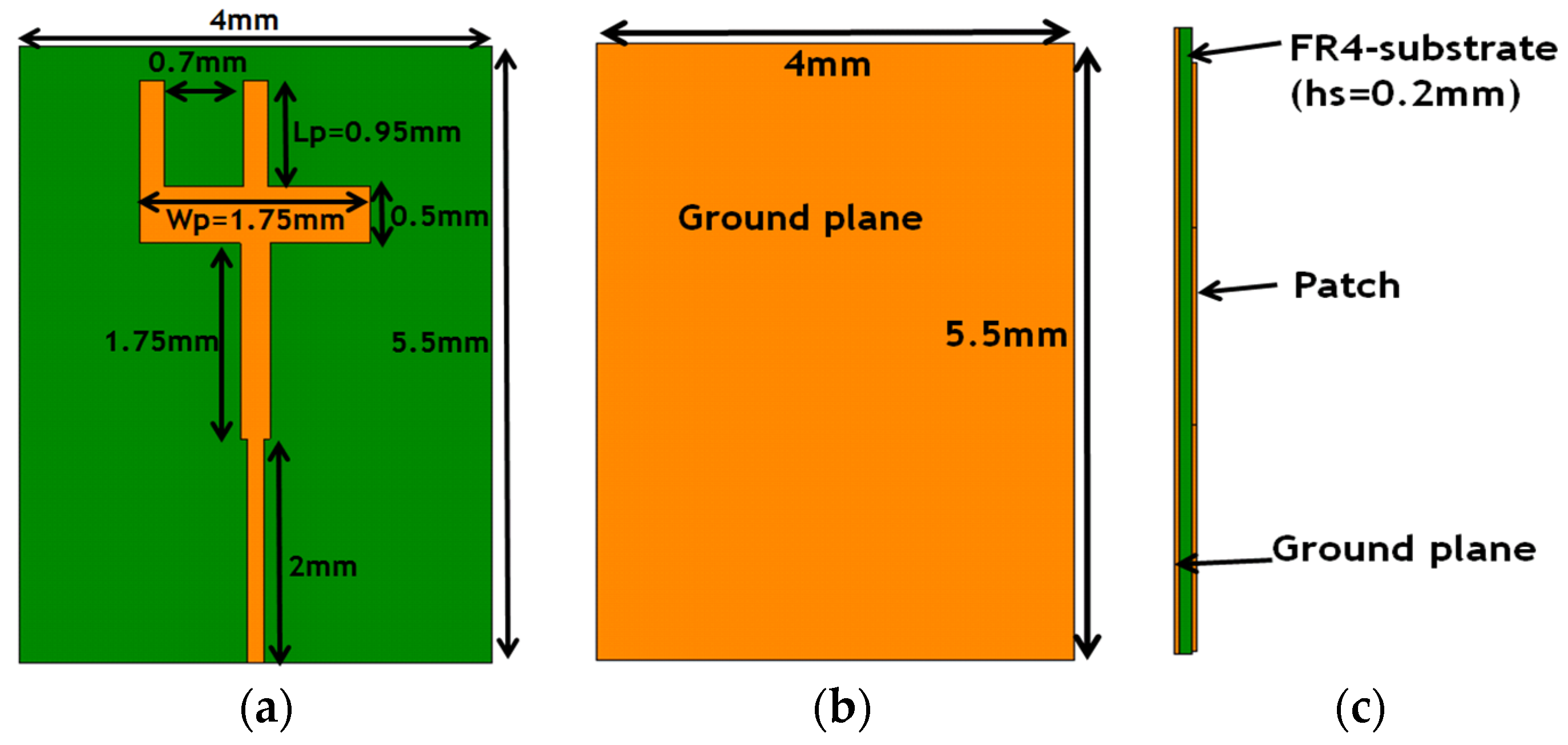
The aim is to design an antenna with a high gain and a directional radiation pattern for mobile phones in next generation mobile communication. Since the millimeter wave band is reserved for future 5G systems, the antennas that operate in this band are of small sizes. The dimensions and the geometry of the antenna are given in Figure 1. This antenna is designed on a FR4 substrate with permittivity, loss tangent tan δ = 0.025 and thickness hs = 0.2 mm. The ground plane dimensions are 5.5 × 4 mm2. To obtain two distinct operating bands, the antenna has the shape of an “inverted-F”. The configuration of the “inverted-F” antenna comprises two L-strip branch: one for the 28 GHz band and the other for the 38 GHz band. The parameter values of the antenna are shown in Figure 1. The antenna was designed and optimized using CST Microwave Studio.
2.2. Parametric Study
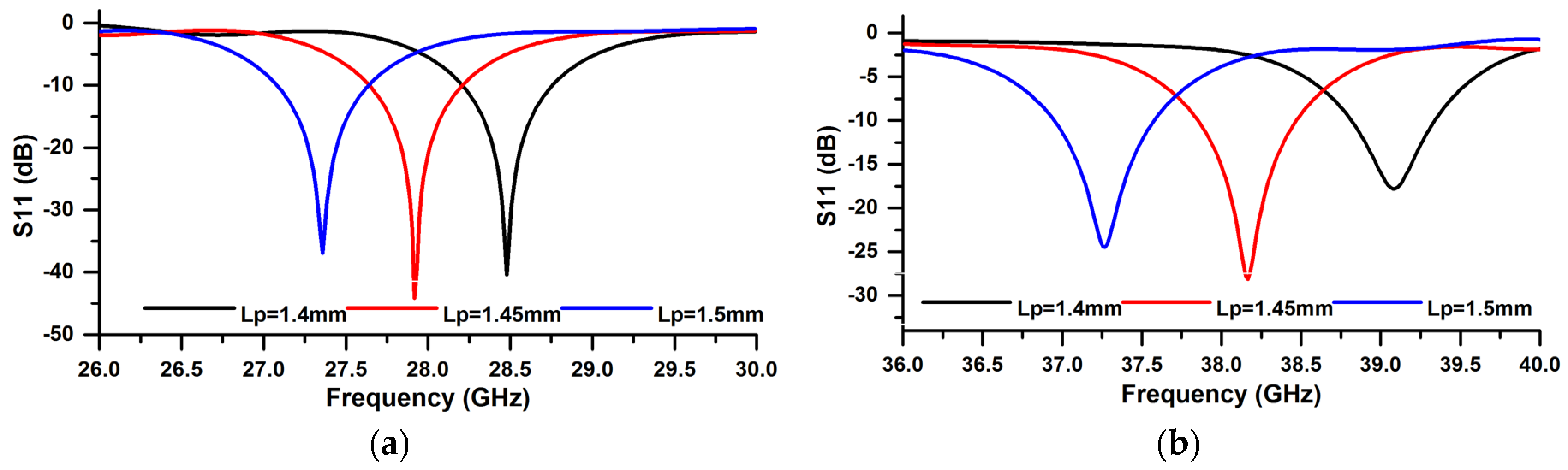
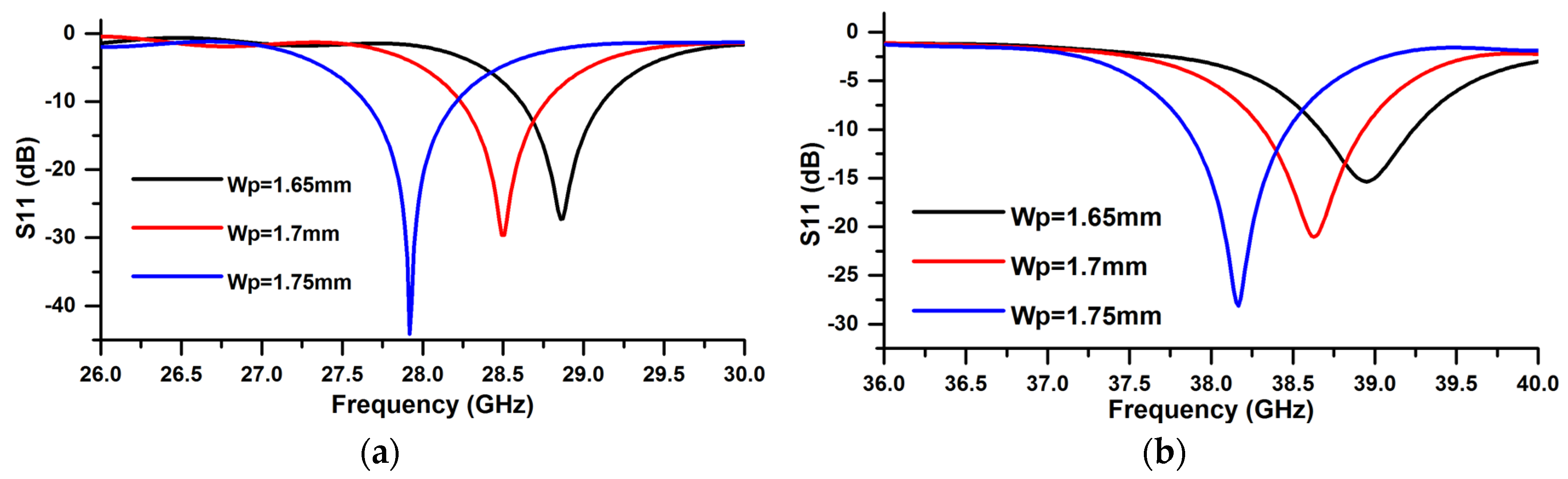
To understand the operating behavior of the 5G antenna, a parametric study is performed by CST microwave studio. Figure 2 shows the effect of the variation of patch length Lp on the reflection coefficient of the antenna (Lp = 1.45 mm, 1.5 mm, 1.55 mm). This figure shows that the resonance frequencies for the two bands 28/38 GHz shift to lower frequency with increasing Lp. The results of the reflection coefficient for the variation of patch width Wp (Wp = 1.65 mm, 1.7 mm, 1.75 mm) are shown in Figure 3. We notice, with increasing Wp, the resonance frequencies in the two bands, 28/38 GHz, shift to lower frequencies.
2.3. Reflection Coefficient
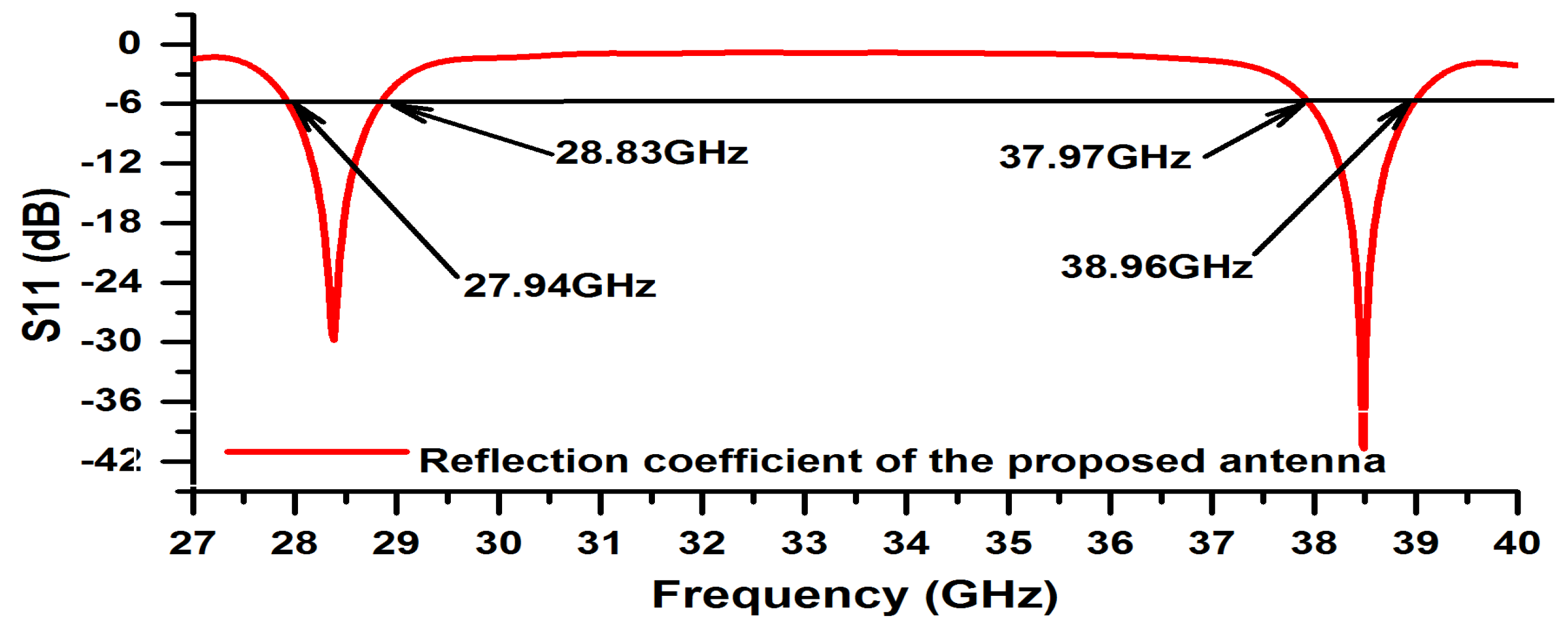
The reflection coefficient for the single element of the 5G antenna is shown in Figure 4. The two operating bands of the antenna are obtained: the first band (S11 < −6 dB) from 27.94 to 28.83 GHz with a width of 890 MHz and the second band from 37.97 to 38.96 GHz with a width of 990 MHz. The two bands obtained cover millimeter-wave frequency bands for future mobile cellular devices.
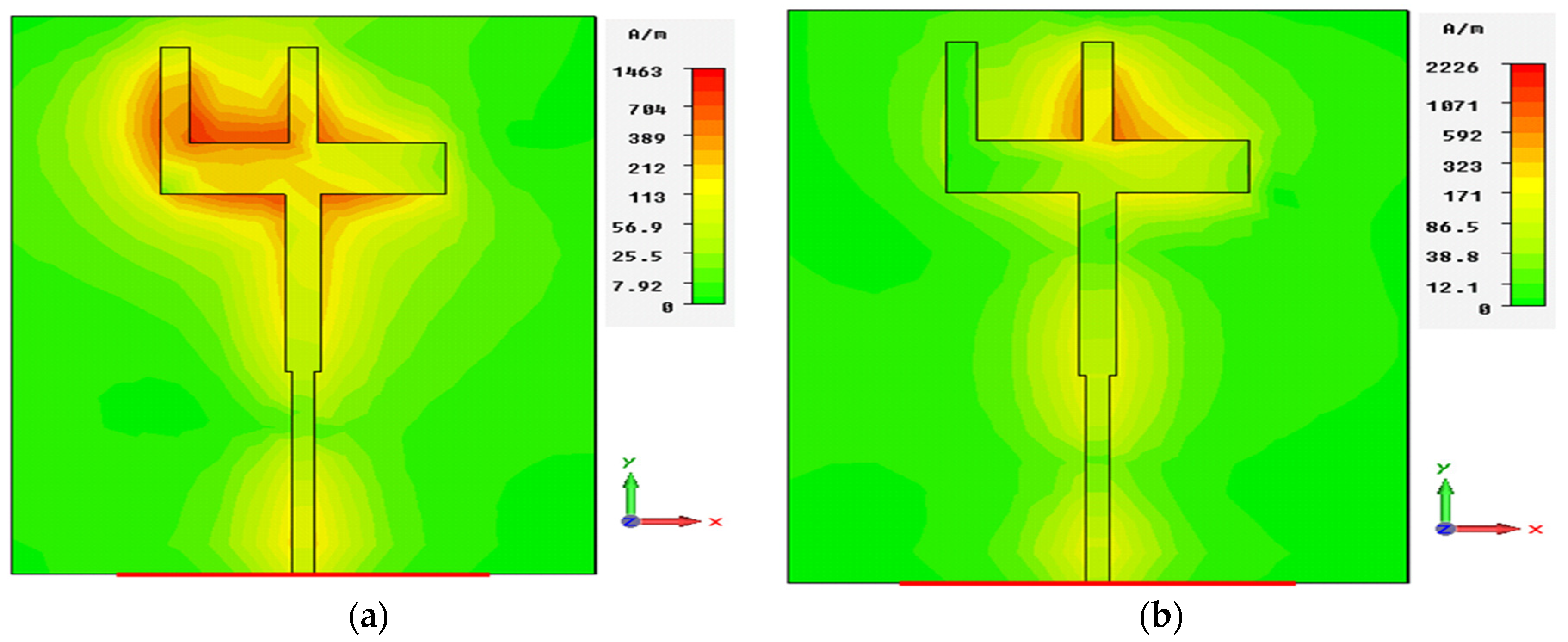
2.4. Current Distribution
To understand the operating mechanism of the antenna, the surface current distribution at both operating bands was studied. The surface current distributions of the 5G antenna at 28.38 and 38.49 GHz are shown in Figure 5a,b, respectively.
Figure 5a shows the simulated current distribution for the “inverted-F” antennas at 28.38 GHz. From this figure, we notice a large current is excited in the L-strip branch left of the “inverted-F”. In Figure 5b, the surface current at 38.49 GHz is distributed in the L-strip branch right of “inverted-F” and has a maximum intensity around this strip.
2.5. Radiation Pattern
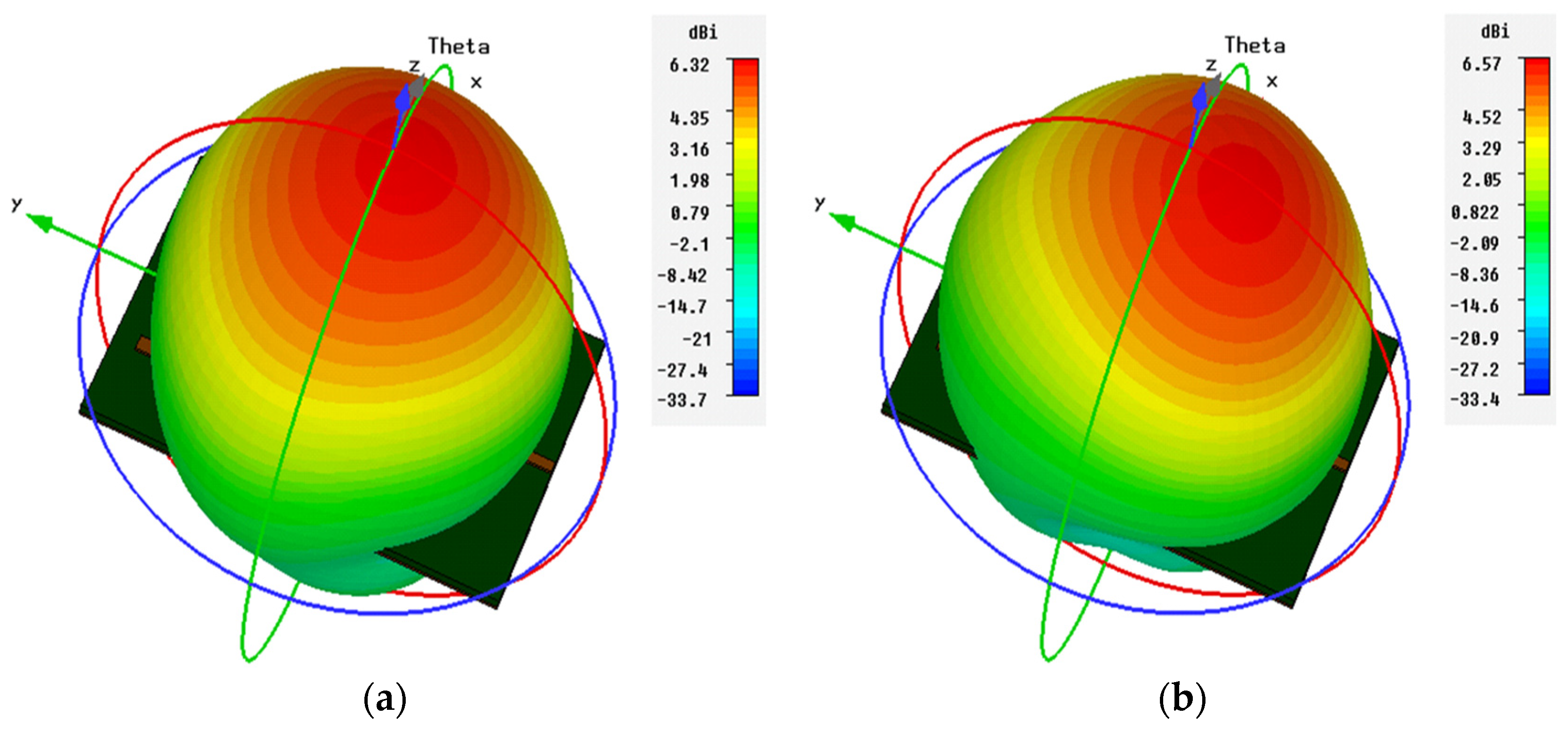
The 3D radiation pattern of the single element “inverted-F” antenna at 28.38 and 38.49 GHz are illustrated in Figure 6a,b, respectively. The obtained results showed that the “inverted-F” antenna had a good end-fire radiation behavior and a gain of 6.22 dB at 28.38 GHz and 6.33 dB at 38.49 GHz.
3. The “Inverted-F” Array Antenna
3.1. The Antenna Array Geometry
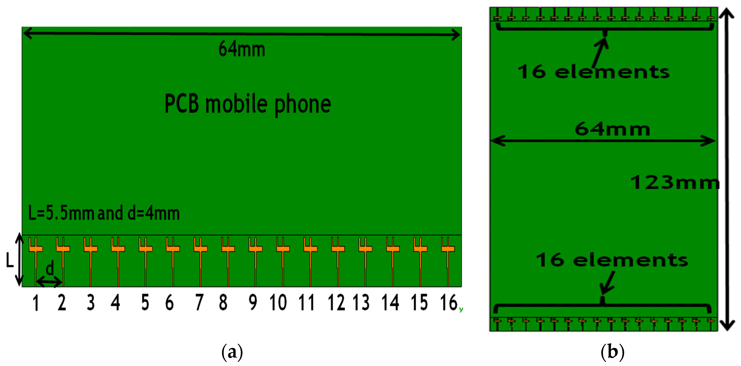
The chosen configuration for the application is a 32 array element with identical elements. Figure 7 shows the geometry of the linear array with 32 elements of the “inverted-F” antennas. The 16 array elements are chosen to be placed in the top portion of PCB, while the other 16 elements are placed in the bottom portion of the PCB. For uniformly spaced linear arrays, the elements have 4 mm spacing between them (0.795λ at 28.38 GHz and 1.076λ at 38.49 GHz). The PCB size is 133 × 64 × 0.2 mm3. The array antenna has been designed, optimized, and simulated using the CST microwave studio.
3.2. The S-Parameters of the Array Antenna
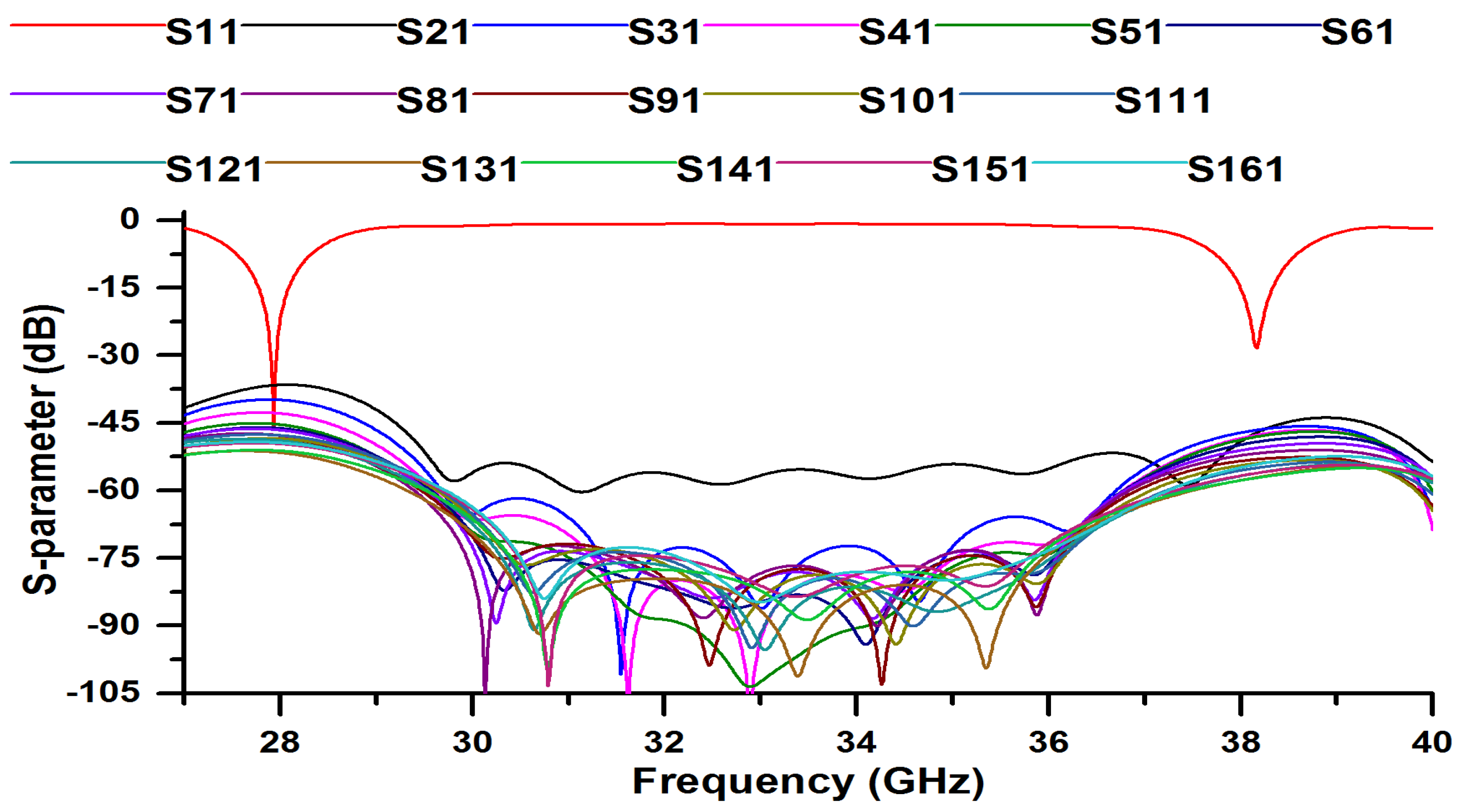
The simulated S-parameters for the array antenna are illustrated in Figure 8. From this figure, we can see that the array antenna exhibits good impedance matching in the 28/38 GHz frequency bands and the mutual-coupling characteristics between the elements are less than −35 dB.
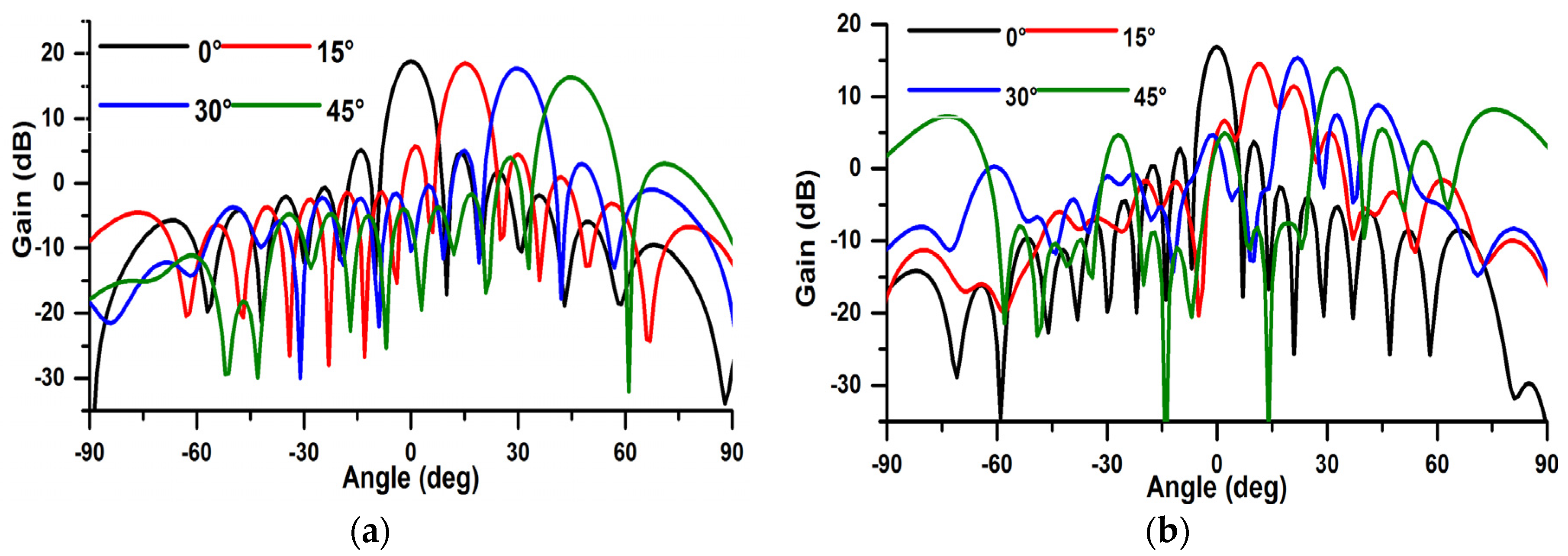
3.3. The Cartesian Gains
The Cartesian gains of the array antenna in x–z plane are displayed in Figure 9. As illustrated, the array antenna has a good beam steering characteristic with end-fire mode and sufficient gains at different scanning angles.
A stable gain with a value of 16.52 dB (+10 dB compared to a single antenna element) at 28.38 GHz is observed in Figure 9a. Additionally, from Figure 9b, we notice that the antenna gain decreases with the increase in the angle; and it is about 15.35 dB in 0° (+9 dB compared to a single antenna element) at 38.49 GHz.
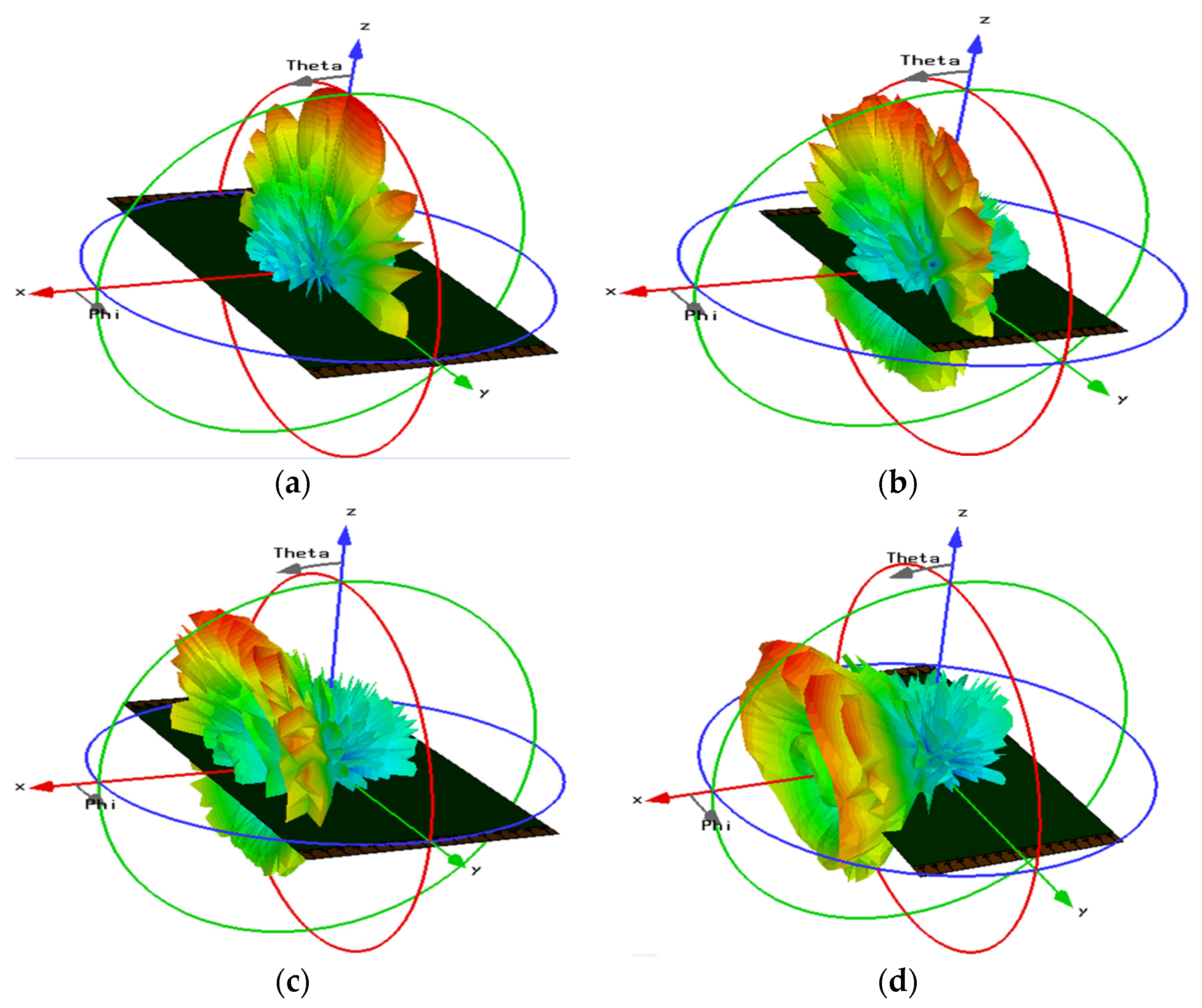
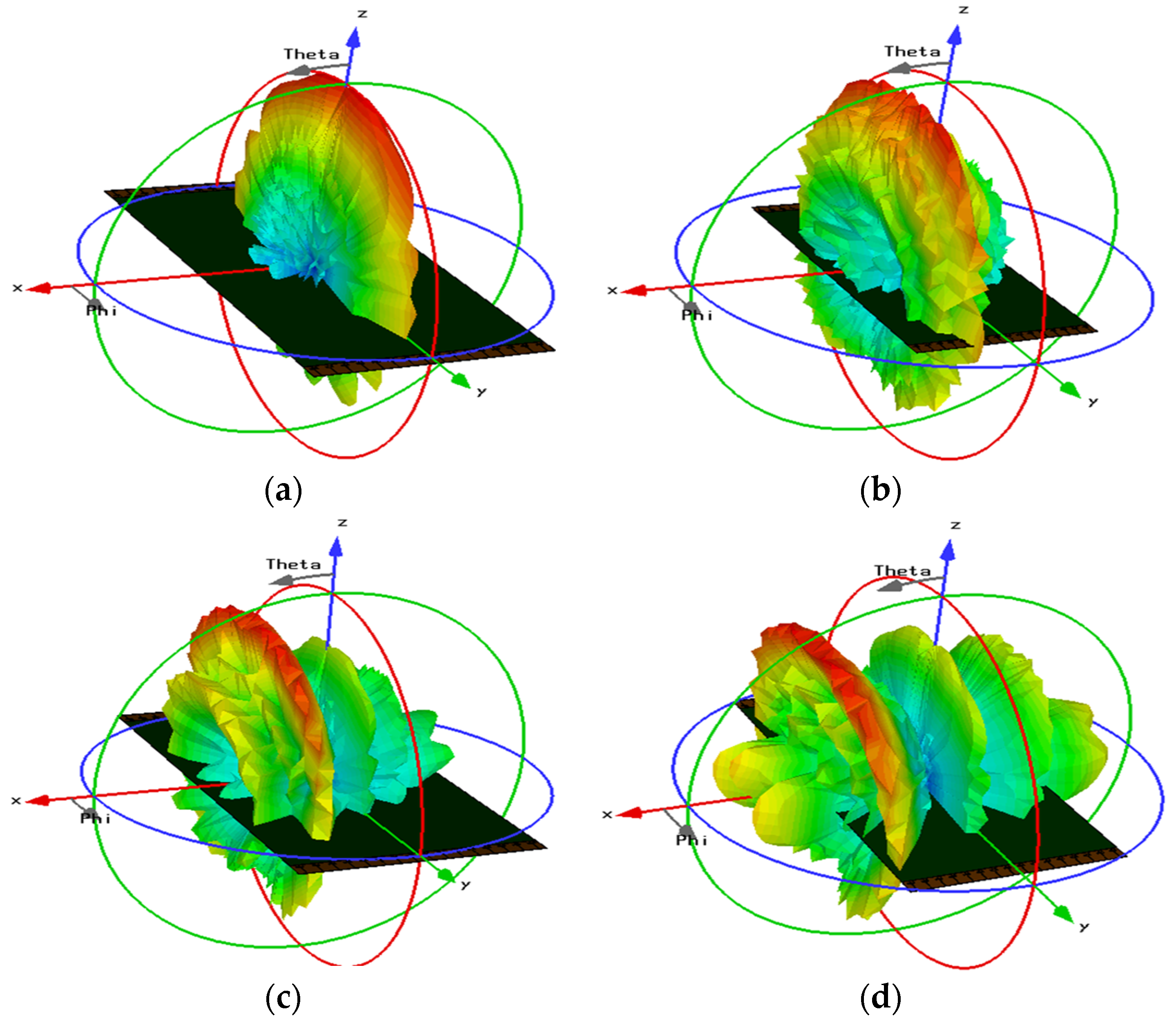
3.4. The Radiation Pattern of the Array Antenna
The beam steering characteristic of the simulated radiation patterns of the 5G antenna in different scanning angles (0° to 45°) is also studied. Figure 10 and Figure 11 show the 3D radiation pattern beams of the array antenna at 28.38 and 38.49 GHz, respectively. The beam steering characteristic of the 5G antenna for plus/minus scanning angles are symmetric [16]. We observe, the array antenna has a good beam steering property which is highly effective to cover the range of ±45° [17].
4. Conclusions
In this paper, a new compact dual-band (28/38 GHz) “inverted-F” array antenna for the future fifth generation (5G) mobile networks have been demonstrated. The 5G antenna is worked in the 28 GHz mm-wave band (27.94–28.83 GHz) and the 38 GHz mm-wave band (37.97–38.96 GHz) with a bandwidth 890 and 990 MHz, respectively. Since the proposed antenna is of small size and simple geometry with the simplicity of reaching the desired frequency bands, it is easy to manufacture and integrate in the case of the OLEDs. The mutual-coupling characteristics between the elements are less than −35 dB. To improve the gain of the antenna, we used the antenna array technique. Therefore, we have reached a high gain of 16.52 dB in the first band and 15.35 dB in the second band. End-fire radiation beams were achieved by employing 32 elements of “inverted-F” antennas on the top and bottom portions of the OLEDs display. With 5G communications, the bandwidth and data rate will be higher, but the distance between receiver and transmitter will be shorter. This makes it necessary to multiply the antennas across an extended network, for example, such as the public lighting network. In this context, this antenna is a good candidate for 5G applications and can be integrated in OLED panels for display as well as in street lighting.
Acknowledgments
This work is granted by PHC Maghreb (Program Hubert Curien) MELINA (Mastering Efficient Lighting In North Africa) funded by Ministry of Europe and Foreign Affairs and supported by Campus France and, in Morocco, by the Ministry of National Education, Professional Training, Higher Education and Scientific Research, in partnership with the National Center for Scientific and Technical Research (CNRST).
References
- Roh, W.; Seol, J.Y.; Park, J.; Lee, B.; Lee, J.; Kim, Y.; Cho, J.; Cheun, K.; Aryanfar, F. Millimeter-wave beam forming as an enabling technology for 5G cellular communications: Theoretical feasibility and prototype results. IEEE Commun. Mag. 2014, 52, 106–113. [Google Scholar] [CrossRef]
- Gupta, A.; Jha, R.K. A Survey of 5G Network: Architecture and Emerging Technologies. IEEE Access 2015, 3, 1206–1232. [Google Scholar] [CrossRef]
- Rappaport, T.S.; Sun, S.; Mayzus, R.; Zhao, H.; Azar, Y.; Wang, K.; Wong, G.N.; Schulz, J.K.; Samimi, M.; Gutierrez, F. Millimeter Wave Mobile Communications for 5G Cellular: It Will Work! IEEE Access 2013, 1, 335–349. [Google Scholar] [CrossRef]
- Rappaport, T.S.; Qiao, Y.; Tamir, J.I.; Murdock, J.N.; Ben-Dor, E. Cellular broadband millimeter wave propagation and angle of arrival for adaptive beam steering systems (invited paper). In Proceedings of the 2012 IEEE Radio and Wireless Symposium (RWS), Santa Clara, CA, USA, 15–18 January 2012; pp. 151–154. [Google Scholar]
- Akdeniz, M.R.; Liu, Y.; Rangan, S.; Erkip, E. Millimeter wave picocellular system evaluation for urban deployments. In Proceedings of the 2013 IEEE Globecom Workshops (GC Wkshps), Atlanta, GA, USA, 9–13 December 2013; pp. 105–110. [Google Scholar]
- El Halaoui, M.; Canale, L.; Asselman, A.; Zissis, G. An Optically Transparent Antenna Integrated in OLED Light Source for 5G Applications. In Proceedings of the 2020 IEEE International Conference on Environment and Electrical Engineering and 2020 IEEE Industrial and Commercial Power Systems Europe (EEEIC/I&CPS Europe), Madrid, Spain, 9–12 June 2020; pp. 1–5. [Google Scholar] [CrossRef]
- Hong, W.; Baek, K.-H.; Lee, Y.; Kim, Y.; Ko, S.-T. Study and prototyping of practically large-scale mm Wave antenna systems for 5G cellular devices. IEEE Commun. Mag. 2014, 52, 63–69. [Google Scholar] [CrossRef]
- Tatomirescu, A.; Oprian, A.; Zhekov, S.; Pedersen, G.F. Beam-steering array for handheld devices targeting 5G. In Proceedings of the 2015 International Symposium on Antennas and Propagation (ISAP), Hobart, Tasmanie, Australia, 9–12 November 2015; pp. 1–4. [Google Scholar]
- El Halaoui, M.; Kaabal, A.; Asselman, H.; Ahyoud, S.; Asselman, A. Multiband Planar Inverted-F Antenna with Independent Operating Bands Control for Mobile Handset Applications. Int. J. Antennas Propag. 2017, 2017, 1–13. [Google Scholar] [CrossRef]
- Helander, J.; Zhao, K.; Ying, Z.; Sjoberg, D. Performance Analysis of Millimeter-Wave Phased Array Antennas in Cellular Handsets. IEEE Antennas Wirel. Propag. Lett. 2015, 15, 504–507. [Google Scholar] [CrossRef]
- Ashraf, N.; Haraz, O.M.; Ali, M.M.M.; Ashraf, M.A.; Alshebili, S.A.S. Optimized broadband and dual-band printed slot antennas for future millimeter wave mobile communication. AEU Int. J. Electron. Commun. 2016, 70, 257–264. [Google Scholar] [CrossRef]
- Bisharat, D.J.; Liao, S.; Xue, Q. High Gain and Low Cost Dierentially Fed Circularly Polarized Planar Aperture Antenna for Broadband Millimeter-Wave Applications. IEEE Trans. Antennas Propag. 2016, 64, 33–42. [Google Scholar] [CrossRef]
- Ojaroudiparchin, N.; Shen, M.; Pedersen, G.F. Multi-layer 5G mobile phone antenna for multi-user MIMO communications. In Proceedings of the 2015 23rd Telecommunications Forum Telfor (TELFOR), Belgrade, Serbia, 24–26 November 2015; pp. 559–562. [Google Scholar]
- Li, W.-Y.; Chung, W.; Wong, K.-L. Highly-Integrated Dual-Band mm Wave Antenna Array for 5G Mobile Phone Application. In Proceedings of the 2020 14th European Conference on Antennas and Propagation (EuCAP), Copenhagen, Denmark, 15–20 March 2020; pp. 1–5. [Google Scholar]
- Wang, Y.; Huang, H.-C.; Jian, X. Integrated Design of a Cable-Fed Dual-Band Dual-Polarization 5G mm-Wave Antenna Array with a U-Slotted Full-Metal Casing for a Cellular Phone. In Proceedings of the 2019 International Conference on Microwave and Millimeter Wave Technology (ICMMT), Guangzhou, China, 19–22 May 2019; pp. 1–3. [Google Scholar]
- Huang, H.-C.; Wang, Y.; Jian, X. Novel Integrated Design of Dual-Band Dual-Polarization mm-Wave Antennas in Non-mm-Wave Antennas (AiA) for a 5G Phone with a Metal Frame. In Proceedings of the 2019 International Workshop on Antenna Technology (iWAT), Miami, FL, USA, 3–6 March 2019; pp. 125–128. [Google Scholar]
- Mahmoud, K.R.; Montaser, A.M. Design of dual-band circularly polarised array antenna package for 5G mobile terminals with beam-steering capabilities. IET Microw. Antennas Propag. 2018, 12, 29–39. [Google Scholar] [CrossRef]
- Li, Y.; Sim, C.-Y.-D.; Luo, Y.; Yang, G. Multiband 10-Antenna Array for Sub-6 GHz MIMO Applications in 5-G Smartphones. IEEE Access 2018, 6, 28041–28053. [Google Scholar] [CrossRef]
- Marzouk, H.M.; Ahmed, M.I.; Shaalan, A.A. A Novel Dual-band 28/38 GHz Slotted Microstip MIMO Antenna for 5G Mobile Applications. In Proceedings of the 2019 IEEE International Symposium on Antennas and Propagation and USNC-URSI Radio Science Meeting, Atlanta, GA, USA, 7–12 July 2019; pp. 607–608. [Google Scholar]
- Deckmyn, T.; Cauwe, M.; Ginste, D.V.; Rogier, H.; Agneessens, S. Dual-Band (28,38) GHz Coupled Quarter-Mode Substrate-Integrated Waveguide Antenna Array for Next-Generation Wireless Systems. IEEE Trans. Antennas Propag. 2019, 67, 2405–2412. [Google Scholar] [CrossRef]
- Rahayu, Y.; Hidayat, M.I. Design of 28/38 GHz Dual-Band Triangular-Shaped Slot Microstrip Antenna Array for 5G Applications. In Proceedings of the 2018 2nd International Conference on Telematics and Future Generation Networks (TAFGEN), Kuching, Malaysia, 24–26 July 2018; pp. 93–97. [Google Scholar]
- Ullah, H.; Tahir, F.A.; Khan, M.U. Dual-band planar spiral monopole antenna for 28/38 GHz frequency bands. In Proceedings of the 2017 IEEE International Symposium on Antennas and Propagation USNC/URSI National Radio Science Meeting, San Diego, CA, USA, 9–14 July 2017; pp. 761–762. [Google Scholar]
Figure 1.
The geometry of the antenna: (a) ground plane, (b) bottom view and (c) side view.

Figure 2.
The reflection coefficient with variation of Lp: (a) at 28 GHz band and (b) at 38 GHz band.
Figure 2.
The reflection coefficient with variation of Lp: (a) at 28 GHz band and (b) at 38 GHz band.

Figure 3.
The reflection coefficient with variation of Wp: (a) at 28 GHz band and (b) at 38 GHz band.
Figure 3.
The reflection coefficient with variation of Wp: (a) at 28 GHz band and (b) at 38 GHz band.

Figure 4.
The reflection coefficient of the antenna.

Figure 5.
Surface current distribution: (a) at 28 GHz band and (b) at 38 GHz band.

Figure 6.
The 3D radiation pattern: (a) at 28 GHz band and (b) at 38 GHz band.

Figure 7.
The geometry of the array antenna: (a) bottom portion of the PCB and (b) top view.

Figure 8.
The S-parameters of the array antenna.

Figure 9.
The cartesian gains of the 5G array antenna: (a) at 28.38 GHz and (b) at 38.49 GHz.

Figure 10.
The 3D radiation beams in 28 GHz band at different scanning angles; (a) 0°, (b) 15°, (c) 30° and (d) 45°.
Figure 10.
The 3D radiation beams in 28 GHz band at different scanning angles; (a) 0°, (b) 15°, (c) 30° and (d) 45°.

Figure 11.
The 3D radiation beams in 38 GHz band at different scanning angles; (a) 0°, (b) 15°, (c) 30° and (d) 45°.
Figure 11.
The 3D radiation beams in 38 GHz band at different scanning angles; (a) 0°, (b) 15°, (c) 30° and (d) 45°.

Publisher’s Note: MDPI stays neutral with regard to jurisdictional claims in published maps and institutional affiliations. |
© 2020 by the authors. Licensee MDPI, Basel, Switzerland. This article is an open access article distributed under the terms and conditions of the Creative Commons Attribution (CC BY) license (http://creativecommons.org/licenses/by/4.0/).
Share and Cite
MDPI and ACS Style
El Halaoui, M.; Canale, L.; Asselman, A.; Zissis, G. Dual-Band 28/38 GHz Inverted-F Array Antenna for Fifth Generation Mobile Applications. Proceedings 2020, 63, 53. https://0-doi-org.brum.beds.ac.uk/10.3390/proceedings2020063053
AMA Style
El Halaoui M, Canale L, Asselman A, Zissis G. Dual-Band 28/38 GHz Inverted-F Array Antenna for Fifth Generation Mobile Applications. Proceedings. 2020; 63(1):53. https://0-doi-org.brum.beds.ac.uk/10.3390/proceedings2020063053
Chicago/Turabian StyleEl Halaoui, Mustapha, Laurent Canale, Adel Asselman, and Georges Zissis. 2020. "Dual-Band 28/38 GHz Inverted-F Array Antenna for Fifth Generation Mobile Applications" Proceedings 63, no. 1: 53. https://0-doi-org.brum.beds.ac.uk/10.3390/proceedings2020063053