Design of Transparent Antenna for 5G Wireless Applications †


1
Optics and Photonics Laboratory, Abdelmalek Essaadi University, 93030 Tetouan, Morocco
2
LAPLACE, Université de Toulouse, CNRS, INPT, UPS 31000 Toulouse, France
3
Information Technology and System Modeling Team, Abdelmalek Essaadi University, 93030 Tetouan, Morocco
*
Author to whom correspondence should be addressed.
†
Presented at the 14th International Conference on Interdisciplinarity in Engineering—INTER-ENG 2020, Târgu Mureș, Romania, 8–9 October 2020.
Proceedings 2020, 63(1), 54; https://0-doi-org.brum.beds.ac.uk/10.3390/proceedings2020063054
Published: 28 December 2020
(This article belongs to the Proceedings of The 14th International Conference on Interdisciplinarity in Engineering—INTER-ENG 2020)
Abstract
:This paper presents the design of a compact size band patch antenna for 5G wireless communications. This wideband antenna was designed on a glass substrate (12 × 11 × 2 mm3) and is optically transparent and compact. It consists of a radiation patch and a ground plane using AgHT-8 material. The antenna design comprises rectangular shaped branches optimized to attain the wideband characteristics. The calculated impedance bandwidth is 7.7% covering the frequency range of 25 to 27 GHz. A prototype of the antenna and various parameters such as return loss plot, gain plot, radiation pattern plot, and voltage standing wave ratio (VSWR) are presented and discussed. The simulated results of this antenna show that it is well suited for future 5G applications because of its transparency, flexibility, light weight, and wide achievable frequency bandwidth near the millimeter wave frequency band.
1. Introduction
Over recent decades, wireless mobile communication technology has developed significantly despite its relatively recent establishment. The fifth generation (5G) mobile communication system will be deployed on a large scale in the next decade, and it will bring us many advantages such as higher transmission rate, high bit rate with lower battery consumption, and shorter latency than the current 4G system [1,2].
Today, the modern telecommunication industries are already moving towards 5G enabled devices, and some are working on fully transparent and flexible devices [3]. Such cases create the need for flexible and transparent antennas to be designed in the 5G and millimeter wave frequency band.
Transparent antennas operating in the wireless frequency regions are useful in glass-mounted applications including automobiles, homes, and businesses where transmission and reception through or from a window is desired. Transparent antennas have been fabricated with AgHT materials, indium tin oxide (ITO) [4,5], and fluorine doped tin oxide on glass and polyimide. The use of a transparent conductor can pose challenges in fabrication and in application [6].
Among them are losses in films with lower conductivities, film thicknesses less than skin depth, and other complications, specifically additional losses and lower radiation efficiency posed by the presence of a transparent ground plane on thin substrates in standard, planar antennas.
The main objective of this work was to design and analyze a transparent antenna operating in the wide frequency band of 26 GHz. The frequency range extends from 25 to 27 GHz, which covers the band for 5G applications. The size of the compact antenna is (12 × 11 × 2 mm3).
2. Literature Review
The antenna design is one of the most important factors to be considered in order to fully utilize the 5G technology. However, a few design issues can affect an antenna’s performance. Aside from that, in fabrication process, mechanical inaccuracies and errors can affect the antenna performance [7]. As presented in Table 1, a number of transparent antenna designs have been proposed in literature such as dual-band [8,9] and ultra-wideband [10,11,12,13] characteristics, but very few cover millimeter wave applications. In Ref. [14], a semi-transparent flexible antenna working in the range of 7 to 13 GHz is proposed for 5G applications using polyethylene terephthalate (PET) and silver nanoparticles.
This paper proposes a transparent patch microstrip antenna working at 26 GHz frequency with compact size, simple shape, and good performance.
3. Antenna Design and Parameters
This section describes in detail the geometrical configuration and a procedure for designing the transparent compact antenna for 5G applications. The concept of designing this antenna is based on the square ring monopole antenna structure.
3.1. Design of Transparent Antenna for 5G
Figure 1 shows the stepwise design evolution of the proposed antenna, which was designed and optimized using CST Microwave Studio software simulator.
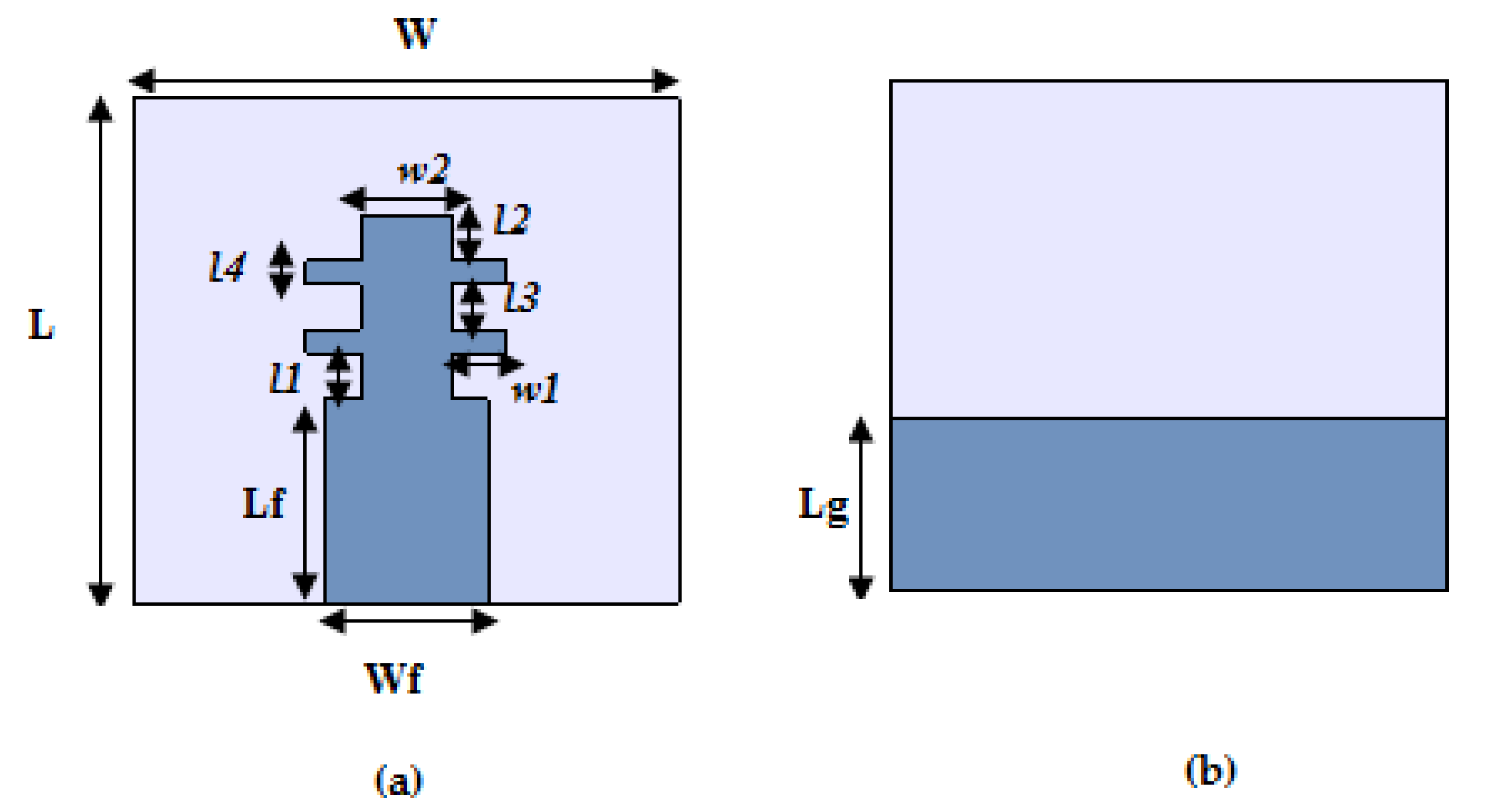
The optically transparent antenna comprises transparent glass with a dielectric constant of 4.82 and 2 mm thickness as the substrate material. Transparent conductive oxide AgHT-8 with a surface resistivity of 8 Ω/m, which is equivalent to the conductivity of 125,000 S/m, constitutes the patch radiator and ground. A feed line with a width of 3.58 mm is used to achieve 50 Ω impedance matching.
3.2. Parametric Study
Parametric investigation of the rectangular arm widths was performed to investigate the performance of the proposed antenna. In this study, rectangular arm width variations are given as terms w1 and w2.
Figure 2 and Figure 3 show the performance of the proposed transparent antenna with the variations of w1 and w2. From Figure 2, it is seen that the return-loss performance is better for w1 = 1.2 mm. When w1 increases from 0.8 to 1.2 mm, the wide bandwidth ranges from 25 to 27 GHz, supporting the bandwidth requirements for 5G. The −10 dB reflection coefficient performance degrades with further decrease in the rectangular arm’s width. From Figure 3, it can be seen that the best impedance matching is obtained as w2 = 2 mm. The center frequency is around 26 GHz, and the bandwidth covered is from 25 to 27 GHz.
The optimum values of w1 and w2 were selected as 1.2 and 2 mm, respectively.
4. Simulation Results and Analysis
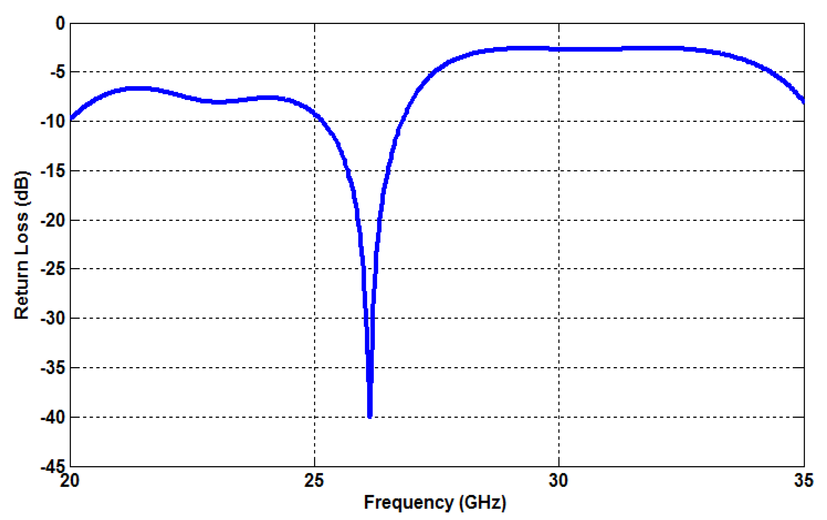
Simulations of the proposed antenna were performed using Computer Simulation Technology (CST) Microwave Studio. An antenna parameter of significant importance in the antenna is the reflection coefficient (S11), which defines the bandwidth and the impedance matching characteristic. The simulated result of the return loss for transparent antenna is depicted in Figure 4. The simulated results show that the single element antenna has a reflection coefficient (S11) of −40 dB, less than −10 dB in the frequency range of 25 to 27 GHz. More than 2 GHz of impedance bandwidth was obtained.
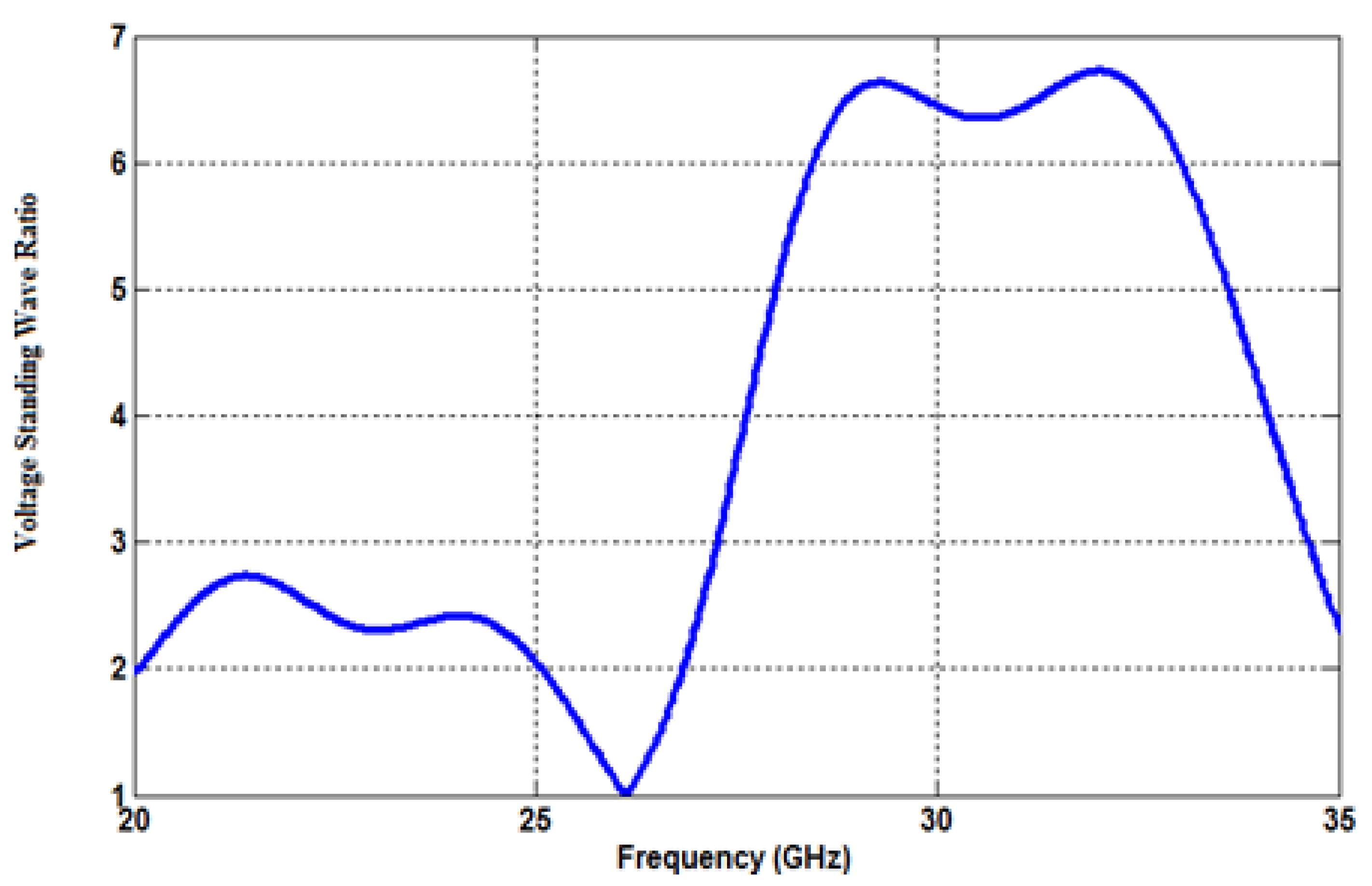
Another imperative parameter beside the reflection coefficient and input impedance that reflects the antenna performance is the voltage standing wave ratio (VSWR). The antenna is only able to operate at frequencies where the values of VSWR are less than 2 (Figure 5).
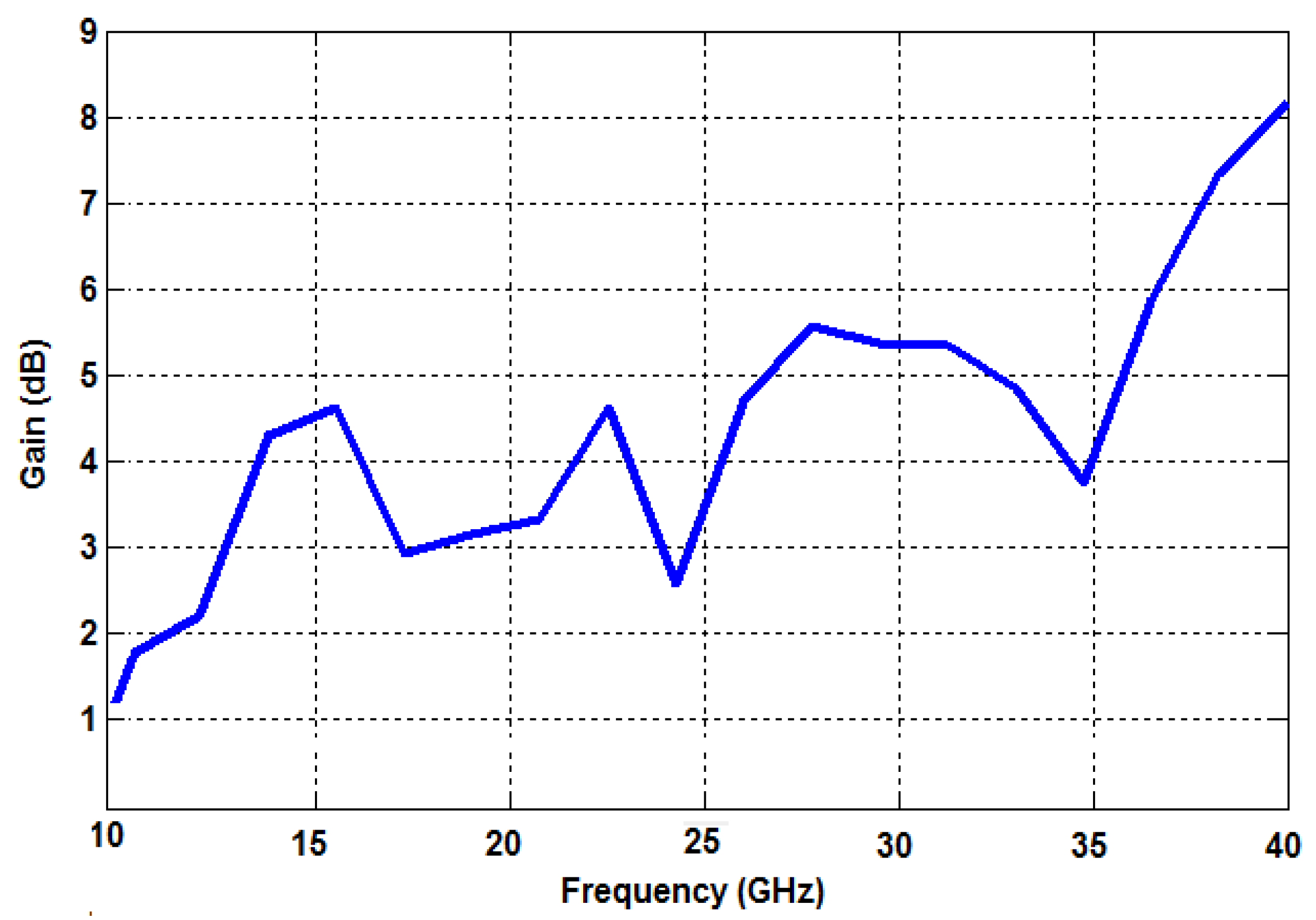
The gain performance of the proposed transparent antenna is shown in Figure 6. The high positive gain performance is observed all over the working frequency band. The peak gain of about 5.5 dB is observed at 26 GHz. This positive gain and widespread radiation pattern ensure the stable performance of the antenna for 5G applications.
The radiation patterns in terms of E-plane and H-Plane are shown in Figure 7. It can be noticed that the E plane radiation pattern appears bi-directional at 26 GHz, and the H plane pattern covers a wide aperture angle with three main orientations.
5. Conclusions
With the development of 5G communication, the integration of transparent antennas on glass surfaces or OLED lighting sources will become a necessity in the next decade. In this study, transparent antennas of simple shape and miniaturized structure were investigated. The proposed antenna is potentially a good option for fifth generation (5G) wireless systems that require high gain topology and low profile. The simulated results show a reflection coefficient of −40 dB with an S11 of less than −10 dB in the frequency range 25 to 27 GHz and an impedance bandwidth of more than 2 GHz. In the future, we will try to manufacture the proposed antenna and compare the radiation pattern and reflection coefficient of the simulated and measured results.
Author Contributions
Conceptualization, S.A. (Sanae Azizi) and S.A. (Saida Ahyoud); methodology, S.A. (Sanae Azizi) and A.A.; validation, L.C., S.A. (Sanae Azizi) and A.A.; formal analysis, S.A. (Sanae Azizi); investigation, S.A. (Sanae Azizi); resources, S.A. (Sanae Azizi); data curation, S.A. (Sanae Azizi), S.A. (Saida Ahyoud) and A.A.; writing—original draft preparation, S.A. (Sanae Azizi), S.A. (Saida Ahyoud), L.C.; writing—review and editing, S.A. (Sanae Azizi), L.C., S.A. (Saida Ahyoud), G.Z. and A.A.; visualization, S.A. (Sanae Azizi), L.C.; supervision, L.C., A.A.; project administration, L.C., A.A.; funding acquisition, L.C. All authors have read and agreed to the published version of the manuscript.
Funding
This research was funded by PHC Maghreb 2020 “MELINA” (Mastering Efficient Lighting in North Africa), grant number 43981ZG–Campus France and supported by the French Ministry of Europe and Foreign Affair and, in Morocco, by the Ministry of National Education, Professional Training, Higher Education and Scientific Research, in partnership with the National Center for Scientific and Technical Research (CNRST).
Acknowledgments
This work is granted by PHC Maghreb (Program Hubert Curien) MELINA (Mastering Efficient Lighting in North Africa) by the French Ministry of Europe and Foreign Affairs and supported by Campus France and, in Morocco, by the Ministry of National Education, Professional Training, Higher Education and Scientific Research, in partnership with the National Center for Scientific and Technical Research (CNRST).
Conflicts of Interest
The authors declare no conflict of interest. The funders had no role in the design of the study; in the collection, analyses, or interpretation of data; in the writing of the manuscript, or in the decision to publish the results.
References
- Haraz, O.M.; Mohamed, M.A.; Saleh, A.; Abdel-Razik, S. Design of a 28/38 GHz dual-band printed slot antenna for the future 5G mobile communication Networks. In Proceedings of the 2015 IEEE International Symposium on Antennas and Propagation & USNC/URSI National Radio Science Meeting, Vancouver, BC, Canada, 19–24 July 2015; pp. 1532–1533. [Google Scholar] [CrossRef]
- Haraz, O.; Mohamed, M.A.; Ayman, E.; Abdel-Razik, S. Four-element dual-band printed slot antenna array for the future 5G mobile communication networks. In Proceedings of the 2015 IEEE International Symposium on Antennas and Propagation & USNC/URSI National Radio Science Meeting, Vancouver, BC, Canada, 19–24 July 2015; pp. 1–2. [Google Scholar] [CrossRef]
- Büschel, W.; Viergutz, A.; Dachselt, R. Towards Interaction with Transparent and Flexible Displays. In Proceedings of the Workshop on ‘Displays Take New Shape: An Agenda for Interactive Surfaces’, Paris, France, 28 April 2013. [Google Scholar]
- Guan, N.; Furuya, N.; Delaune, D.; Ito, K. Antennas made of transparent conductive films. PIERS Online 2008, 4, 116–120. [Google Scholar]
- Sun, G.; Badar, M.; Qi, Z. A study of microstrip antenna made of transparent ITO films. In Proceedings of the 2014 IEEE Antennas and Propagation Society International Symposium (APSURSI), Memphis, TN, USA, 6–11 July 2014; pp. 1867–1868. [Google Scholar] [CrossRef]
- Saberin, J.R.; Furse, C. Challenges with Optically Transparent Patch Antennas. IEEE Antennas Propag. Mag. 2012, 54, 10–16. [Google Scholar] [CrossRef]
- Outerelo, D.A.; Alejos, A.A.; Sanchez, M.G.; Isasa, M.V. Microstrip antenna for 5G broadband communications: Overview of design issues. In Proceedings of the 2015 IEEE International Symposium on Antennas and Propagation & USNC/URSI National Radio Science Meeting, Vancouver, BC, Canada, 19–25 July 2015; pp. 2443–2444. [Google Scholar] [CrossRef]
- Upadhyaya, T.; Arpan, D.; Riki, P.; Upesh, P.; Kanwar, P.K.; Killol, P. Compact transparent conductive oxide based dual band antenna for wireless applications. In Proceedings of the 2017 Progress in Electromagnetics Research Symposium-Fall (PIERS-FALL), Singapore, 19–22 November 2017; pp. 41–45. [Google Scholar] [CrossRef]
- Desai, A.; Trushit, U.; Merih, P.; Riki, P.; Upesh, P. Dual band optically transparent antenna for wireless applications. In Proceedings of the 2017 IEEE Asia Pacific Microwave Conference (APMC), Kuala Lumpar, Malaysia, 13–16 November 2017; pp. 960–963. [Google Scholar] [CrossRef]
- Katsounaros, A.; Hao, Y.; Collings, N.; Crossland, W.A. Optically Transparent Ultra-Wideband Antenna. Electron. Lett. 2009, 45, 722–723. [Google Scholar] [CrossRef]
- Peter, T.; Yuk, T.I.; Nilavalan, R.; Cheung, S.W. A novel technique to improve gain in transparent UWB antennas. In Proceedings of the 2011 Loughborough Antennas & Propagation Conference, Loughborough, UK, 14–15 November 2011; pp. 1–4. [Google Scholar] [CrossRef]
- Peter, T.; Tharek, A.R.; Cheung, S.W.; Rajagopal, N.; Hattan, F.A.; Antonio, V. A Novel Transparent UWB Antenna for Photovoltaic Solar Panel Integration and RF Energy Harvesting. IEEE Trans. Antennas Propag. 2014, 62, 1844–1853. [Google Scholar] [CrossRef]
- Hakimi, S.; Sharul, K.A.R.; Mohammad, A.; Noghabaei, S.M.; Khalily, M. CPW-Fed Transparent Antenna for Extended Ultrawideband Applications. IEEE Antennas Wirel. Propag. Lett. 2014, 13, 1251–1254. [Google Scholar] [CrossRef]
- Tighezza, M.; Rahim, S.K.A.; Islam, M.T. Flexible Wideband Antenna for 5G Applications. Microw. Opt. Technol. Lett. 2018, 60, 38–44. [Google Scholar] [CrossRef]
Figure 1.
Geometry of proposed transparent antenna. (a) Front view; (b) rear view.

Figure 2.
Antenna performance with the variations in term w1.

Figure 3.
Antenna performance with the variations in term w2.

Figure 4.
Simulated return loss (S11) for proposed antenna.

Figure 5.
Voltage standing wave ratio (VSWR) values of the single element antenna.

Figure 6.
Simulated peak gain of the proposed antenna.

Figure 7.
(a) E-plane radiation pattern at 26 GHz; (b) H-plane radiation pattern at 26 GHz.


Table 1.
Comparison of the proposed transparent antenna with other existing antennas.
| Ref | Operating Bands (GHz) | Return Loss at Resonance (dB) | Gain (dB) | Transparent | Size (mm2) |
|---|---|---|---|---|---|
| [14] | 7–13 | <10 | 5 | Semi-transparent | 60 × 75 |
| [12] | 2.2–12.1 | <10 | 3–5 | Yes | 17 × 33.5 |
| [11] | 2–13 | <10 | 1.5–3 | Yes | 20 × 20 |
| Proposed antenna | 25–27 | 40 | 5.5 | Yes | 12 × 11 |
Table 2.
Dimensions of the proposed antenna.
| Parameters | Dimension (in mm) |
|---|---|
| L | 11 |
| W | 12 |
| Wf | 3.58 |
| Lf | 4.45 |
| L1 | 1 |
| L2 | 1 |
| L3 | 1 |
| L4 | 0.5 |
| w1 | 1.2 |
| w2 | 2 |
| Lg | 4.4 |
| tm | 0.0177 |
| hs | 2 |
Publisher’s Note: MDPI stays neutral with regard to jurisdictional claims in published maps and institutional affiliations. |
© 2020 by the authors. Licensee MDPI, Basel, Switzerland. This article is an open access article distributed under the terms and conditions of the Creative Commons Attribution (CC BY) license (http://creativecommons.org/licenses/by/4.0/).
Share and Cite
MDPI and ACS Style
Azizi, S.; Canale, L.; Ahyoud, S.; Zissis, G.; Asselman, A. Design of Transparent Antenna for 5G Wireless Applications. Proceedings 2020, 63, 54. https://0-doi-org.brum.beds.ac.uk/10.3390/proceedings2020063054
AMA Style
Azizi S, Canale L, Ahyoud S, Zissis G, Asselman A. Design of Transparent Antenna for 5G Wireless Applications. Proceedings. 2020; 63(1):54. https://0-doi-org.brum.beds.ac.uk/10.3390/proceedings2020063054
Chicago/Turabian StyleAzizi, Sanae, Laurent Canale, Saida Ahyoud, Georges Zissis, and Adel Asselman. 2020. "Design of Transparent Antenna for 5G Wireless Applications" Proceedings 63, no. 1: 54. https://0-doi-org.brum.beds.ac.uk/10.3390/proceedings2020063054