Peculiarities Regarding the Reconstruction of a Broken Grooved Shaft †

“George Emil Palade” University of Medicine, Pharmacy, Science and Technology of Târgu Mureș, Gh. Marinescu 38, 540142 Târgu Mureș, Romania
*
Author to whom correspondence should be addressed.
†
Presented at the 14th International Conference on Interdisciplinarity in Engineering—INTER-ENG 2020, Târgu Mureș, Romania, 8–9 October 2020.
Proceedings 2020, 63(1), 65; https://0-doi-org.brum.beds.ac.uk/10.3390/proceedings2020063065
Published: 22 January 2021
(This article belongs to the Proceedings of The 14th International Conference on Interdisciplinarity in Engineering—INTER-ENG 2020)
Abstract
:The work remarks the peculiarities, which appeared in the reconstruction of a broken grooved shaft. The originality of the subject consists of the realization of a slotting tool, in material changing, which increased the reliability of the piece, and the total time of measuring the allocation to the work. The dimensional aspects specified include the adjustment, the tool making for profiling the groove, the choice of the material, and the required time to design and build the new spare part.
1. Introduction
Argument: for the machinery park to work with maximum, economic efficiency of mechanization and works automation, in addition to rational exploatation and the proper maintenance, the organization must be ensured and performing current and capitals repairs at a high technical level as well as of assemblies, [1].
The studied grooved shaft can be seen in Figure 1. The first findings on the damaged piece are as follows:
- -
- the groove is made through injection up to the polyamide;
- -
- contains two profiles, grooved and prismatic;
- -
- has the number z = 12 (channels);
- -
- has two bores, the smallest being intended for fixing the coupling with an M5 screw.
2. Working Method
The construction stages of the new grooved shaft are as follows:
- -
- determining the dimensions of the damaged piece;
- -
- the execution of the drawings nedeed;
- -
- material choosing;
- -
- establishing the method of manufacturing the part;
- -
- determining the time required for the manufacture;
- -
- determining deviations of the new grooved shaft.
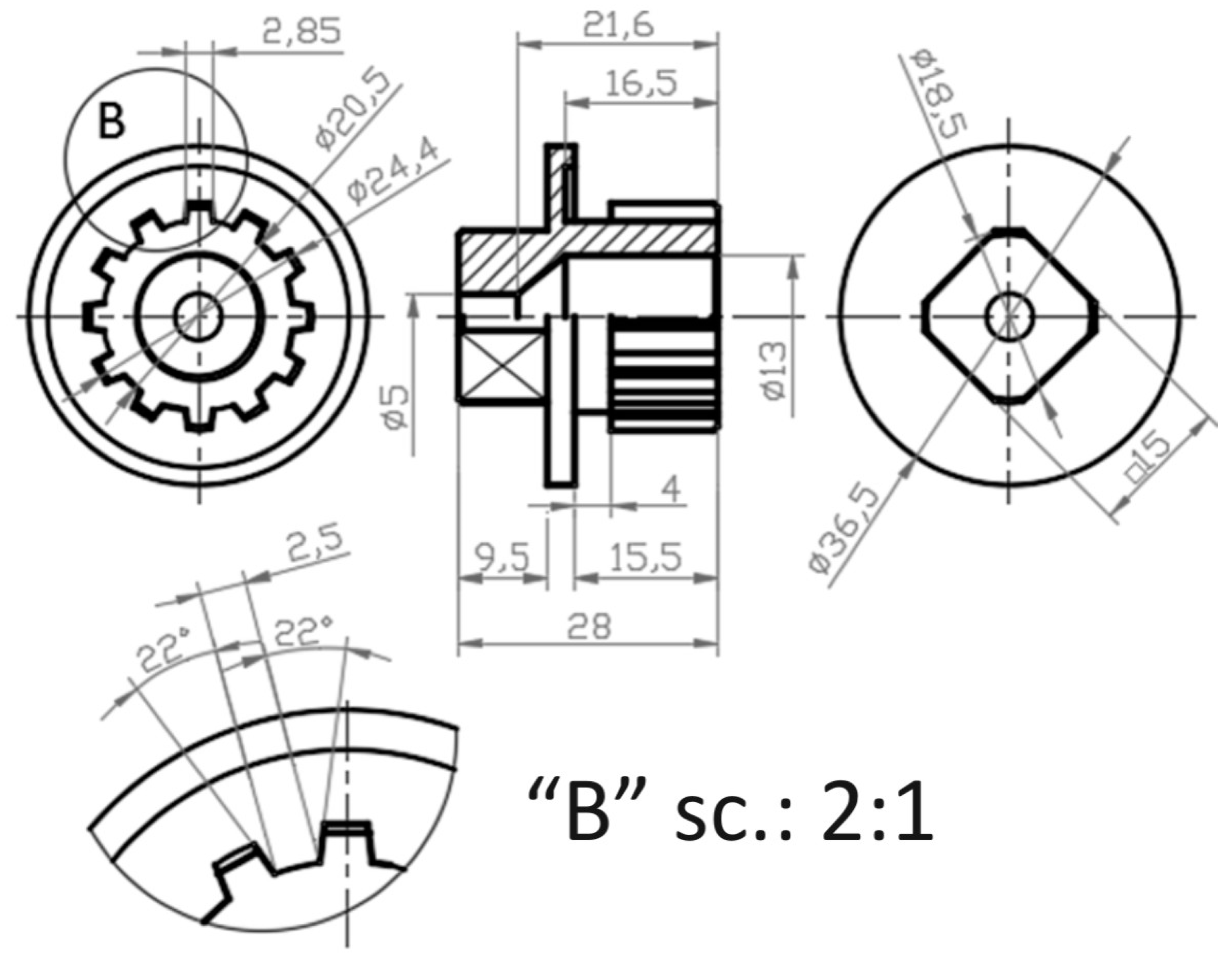
2.1. Dimensions of the Piece and Execution Drawing
The dimensions determining the defective piece are shown in Figure 2. It was achieved with some difficulty due to the advanced state of deterioration caused by impact. For dimensional detection it were used two micrometers of the exterior with an aperture of 0–25 and 25–50 mm were used for the measurements, having an accuracy of 0.01 mm and a caliper with a rod having an accuracy of 0.02 mm.
The CAD design media—Inventor Autodesk was used to elaboration on the drawings present in this paper. Groove assemblies are shaft-hub assemblies designed to transmit torque and rotational motion, [2].
The shape of the groove protrusion is identified with the rectangular profile, but the piece which is made of polyamide, does not insist on the aspects related to the precision of execution (with external centering, with internal centering or with centering on the flanks). Argument: regardless of the category in which they fall, plastics have a high specific coefficient of expansion due to the Van der Walls bonds (week bonds) between the chains and their conformation, [4,5].
The affected accuracy of the part in question is shown—Table 1.
2.2. Choosing of the Material for the Grooved Shaft
The main framings of the polyamide are: Polyamide 6 (PA 6) and Polyamide 6.6 (PA 66). However by modifying the chemical structures (chain length and chemical organization), several other families of polyamides are obtained: PA 4.6; PA 6.10; PA 10.10; PA 11 and PA 12, [6].
Determining the type of polyamide that made up the defective piece was not insisted on, since another material will be chosen. The argument for this option as follows:
- -
- it is desired to use a material with better properties in terms of impact/collision at breakage;
- -
- since the piece will be machined by splintering, the newly chosen material must have technological and thermal properties superior to the original one;
- -
- only one piece will be processed;
In order to improve the strength and hardness or of some technological properties (splintering, material castability, etc.), aluminum alloys with Mg, Cu, Mn, Ni, Zn, Ti, Li, Bi, Sb, etc. [7].
For the manufacturing process of the part was used the material: EN AW-6061/AlMg1SiCu (EN 573-3-2007) [5].
2.3. Machining of the New Grooved Piece
Of all technological processes necessary for execution of equipment, machinery, machines, the one of mechanical processing is most complex [8].
The notion of manufacture derives from two latin words manus (hand) and factus (to do), resulting combination meaning “hand made”. The formal term of “hand made” accurately described the manual methods used until the word “manufacture” was coined around 1567 [9], and it used as a verb, it first appears around 1683 [10]. Next, the piece will not be “hand made” totally, so we have the elements of technological process of mechanical processing are: operation, placement/position, phase, passage, handling and movement, [8]. The unique manufacturing system of the piece will use classic machine tools, a universal lathe SNB 400 × 750 [11] and a milling cutter machine FUS 22, [12].
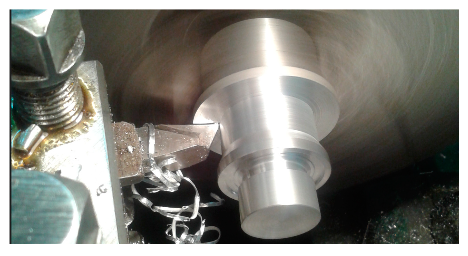
2.4. Initial Turning of the Grooved Shaft
The processings performed on SNB 400 × 750, inside the machine tool laboratory of “George Emil Palade” UMFST of Târgu Mureş, are classic cutting operations, so this paragraph will not be developed, except for Figure 3, in order to argue the shape evolution of the semi-couple during its fabrication.
2.5. Mortising the Grooved Profile
The manufacturing preparation of the FUS 22 machine (equiped with a slotter ram) takes into account the adjustment of MDPT system (machine, device, part and tool) as follows:
- -
- design and construction, as well the related holder bar for the slotting tool;
- -
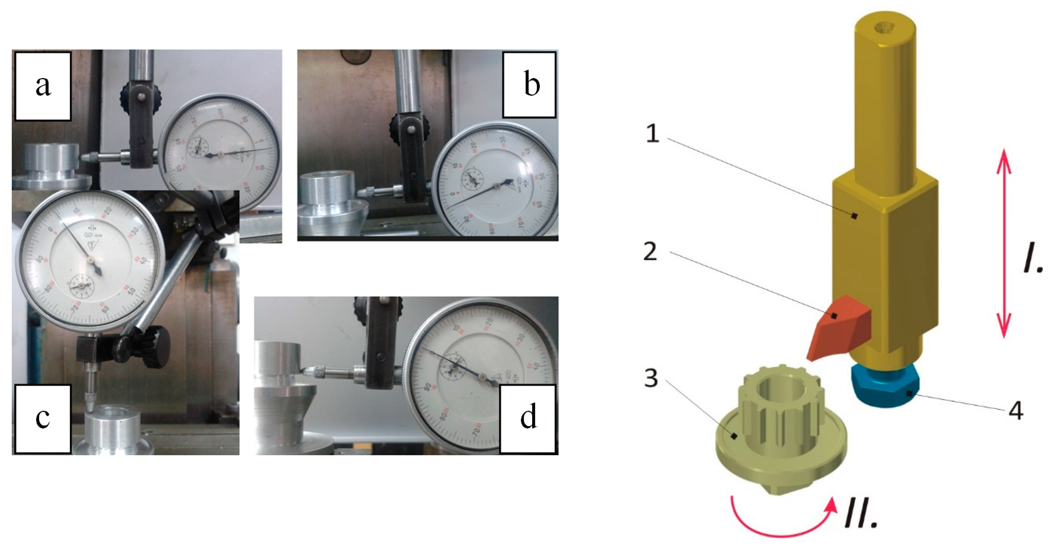
- the piece centered in the universal of the index head and the axis centered of the slotter ram with respect to the axis of the piece, implicitly of the index head, can be observed in Figure 4.
When mortising, the main movement (alternating rectilinear) is performed vertically by the tool, and the feed movement (intermittent) is performed, at the end of each inactive stroke of tool [13,14], in the horizontal plane, also by the tool, however, in the transverse direction (particular case on—FUS 22 machine). By slotting, flat vertical surfaces can be generated with curvilinear profiles, channels of wedge, inner or outer grooves and teeth, etc. [13,14]. In the Figure 4, you can see the 3D model of the theoretical sintesis of the mortise process and the measurement of the deviations of fixing the piece in the universal slotter ram on the machine tool FUS 22:
- -
- The measurement of the radial beat on surface “D”at a complete rotation of 360 °, the result of dimensional deviation is exactly 0.03 mm;
- -
- Axial deviation out of the X direction on surface “D” of the part, result of dimensional deviation is exactly 0.035 mm;
- -
- Axial deviation out of the Y direction on surface “D” of the part, the result of dimensional deviation is exactly 0.00 mm;
- -
- Measuring the frontal beat on surface “A” at a complete rotation of 360°, the result of dimensional deviation is exactly 0.045 mm.
After the mounting index head and slotter ram, both the semi-finished and the slotting tool, Kinematic adjustment parameters are established on the FUS 22 machine and after the positioning adjustments [15]: the main movement (alternative rectilinear) of the slotting tool ncd = 50 dr/min, the cutting advance s = manual, and an empirical calculation—s = 0.0359 mm/dr, is being determined by knowing the timing (3′5″), to displacement at the cutting depth t = 1.95 mm. About for the splintering knife-tool, the name is generally adopted for a wide range of single-tooth tools used in cutting processes, on universal lathes, revolver lathes, automatic, and semi-automatic, carousel lathes, on mortising, grinders, on boring machine, a.o. [16].
In Figure 5 you can see the scheme of the robot part that defines all the machined surfaces of the finished part.
Depending on temperature at they work, tools steels for cold processing, non-alloy and alloyed, with working temperature below 200 °C and tool steels for hot machining, alloyed, at which working temperature is over 200 °C, [7].
In Figure 6 you can see the details of the geometry of the active part of the mortising cutting tool, as well as the fixing in the mortising device.
Only one piece (aluminum) is fabricated, thus the chosen material for the mortise knife is C105U 1.1545 (SR EN ISO 4957:2002), [7].
According to the classification [15,17], the full name of the tool for cutting the groove is: Radial slotting tool of high-speed steel with a profile. In Figure 7 you can see all the geometric and constructive elements of the radial slotting cutting tool.
Following is the calculation of the simple indirect division [12,13] for the rotation of the index head axis at each executed channel (out of the 12 required channels): GD is the number of holes on a circumference of disk D; k is the number of traveled holes; ZP is the number of divisions on the surface of the piece, relation (1). Therefore each channel will be divided, rotating the crank of the index head to three complete rotations, on a circle of GD = 36 holes plus k = 12 additional holes displaced on GD.
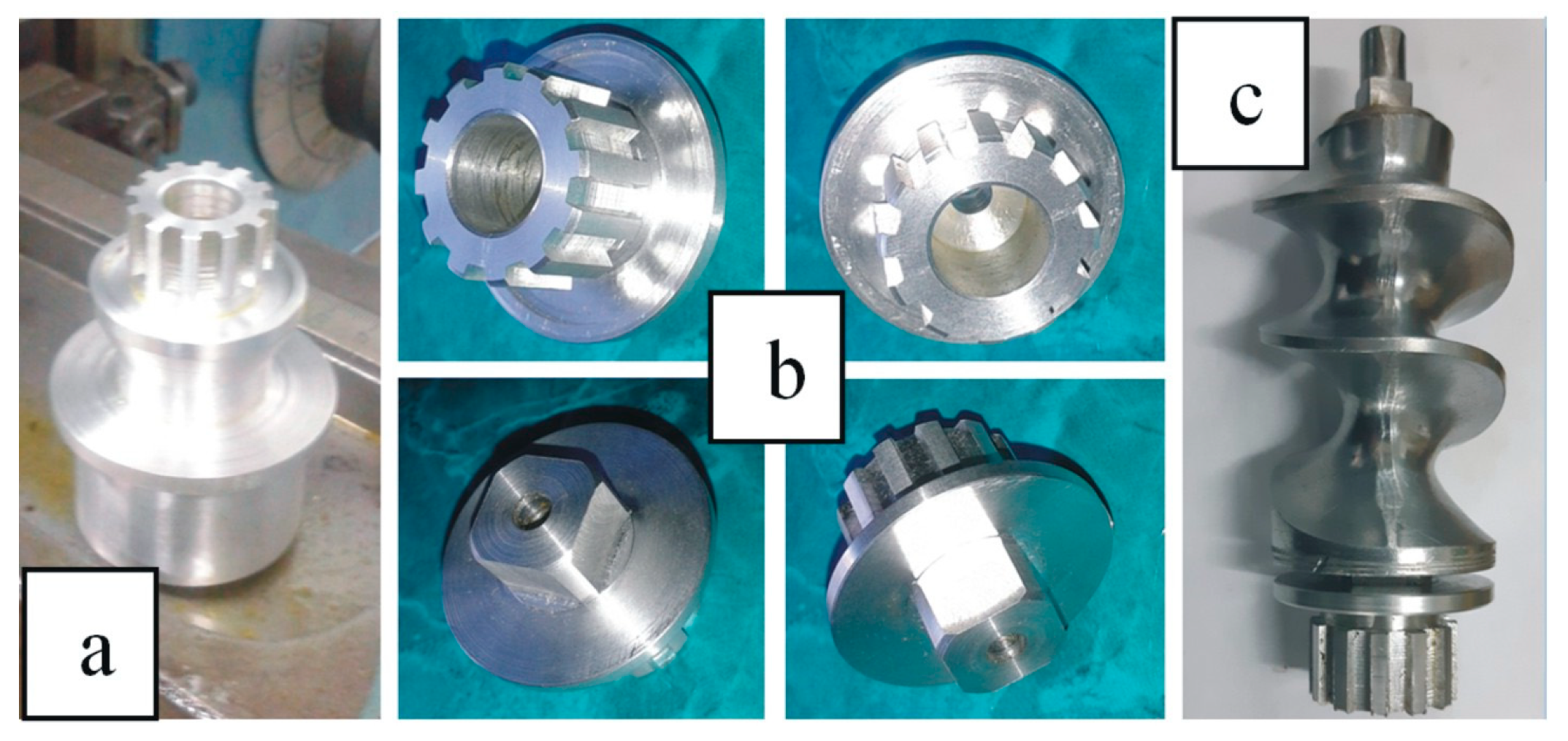
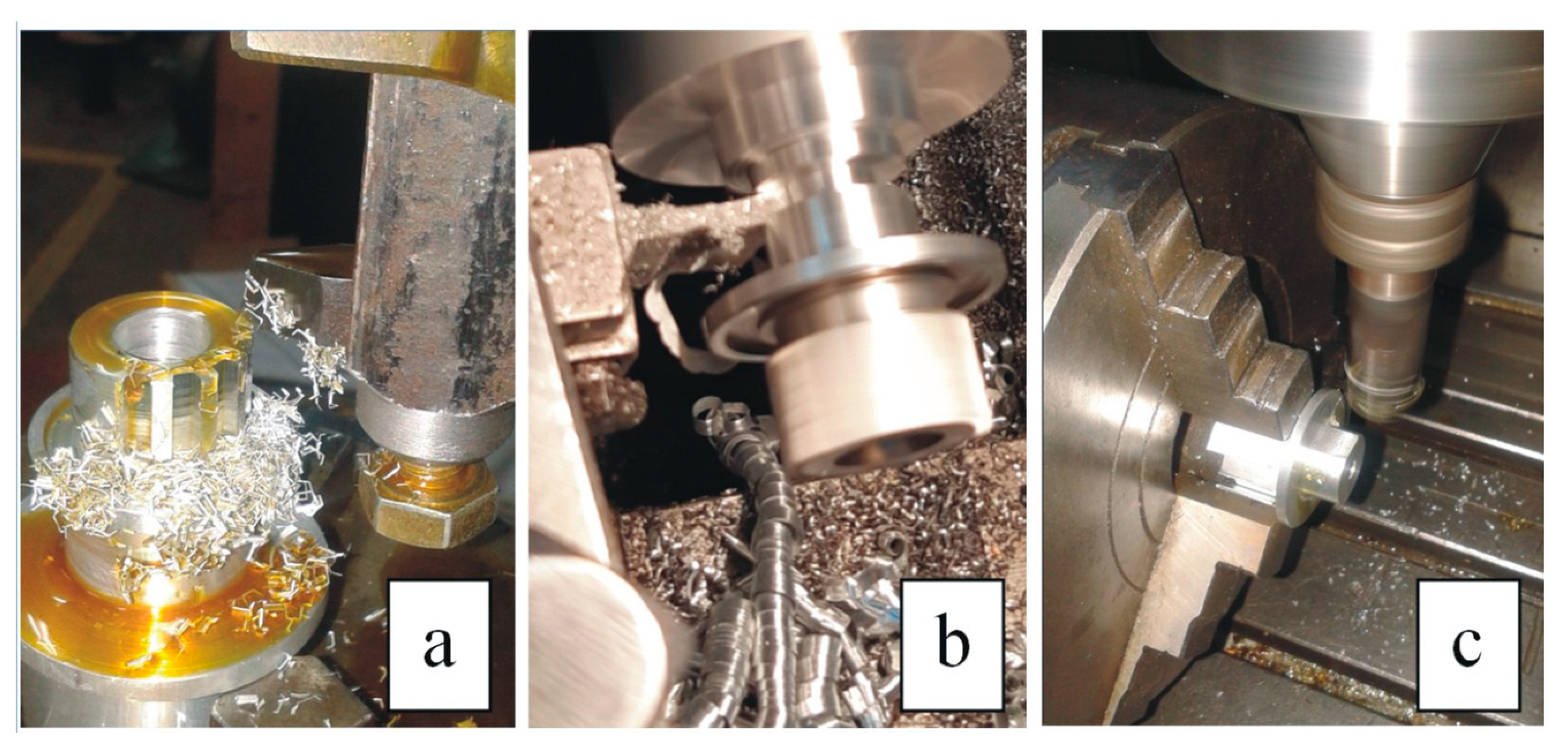
In Figure 8 you can see practical aspects about manufacturing process of tne grooved shaft.
3. Results and Discussion
The total time includes: 1 h measurements + 1 h parametric modeling of three drawings + 1 h 55′ slotting tool construction + 2 h 40′ turning + 2 h 54′ mortising + 1 h 19′ turning again + 1 h 30′ square profile milling, with a total of 11 h 38’. It is not possible to assess whether the realized time (11 h 38′) is more or less, achived. It would be desirable to conduct a theoretical calculation of time, for edification. Figure 9 shows the final result of the technological method approached for the manufacture of the grooved shaft, as well as the assembly whit conjugate part.
For the working method presented, all the photo present in this paper are original and were taken in the laboratory M.U.—A014 of the “George Emil Palade” University of Medicine, Pharmacy, Science and Technologie of Targu Mures, Roamania.
4. Conclusions
The dimensions of the defective piece have been determined, in the Inventor-Autodesk enviroment. The necessary 2D and 3D drawings were designed, all the necessary technological steps, necessary tools, and adjustment of the machine tools were completed.
The slotting tool was conceived and built by the auto-endowment, and saving acquisition costs.
It was possible to piece the fabricate in required parameters, according to the endowment of the laboratory. Therefore, no other faster or cheaper fabricatione ways are disputed (3D printing or CAD/CAM). In this sense, it would be interesting to have a comparison.
References
- Paraschiv, D. Metal Surface Reconditioning and Processing of the ManufacturingTechnologies (Tehnologii de Recondiţionare şi Procesări ale Suprafeţelor Metalice); Junimea Publishing House: Iasi, Romania, 2005. [Google Scholar]
- Jula, A.; Lateş, M. Machine Parts (Organe de Maşini); Transilvania University Publishing House: Braşov, Romania, 2004. [Google Scholar]
- Tero, M.; Bucur, B.; Bratu, G. Descriptive Geometry and Technical Drawing (Geometrie Descriptivă şi Desen Tehnic); Napoca STAR Publishing House: Cluj-Napoca, Romania, 2013. [Google Scholar]
- Available online: https://gsb-international.de/media/pdftoimage/4C6A17BD7A044FB8B71D8F0108F4F21C.PDF (accessed on 31 December 2020).
- Available online: https://metcenter.ru/f/en_573-3.pdf (accessed on 31 December 2020).
- Available online: https://www.resinex.ro/tipurile-de-polimeri/pa.html (accessed on 31 December 2020).
- Socaciu, T. Elements of the Materials Science and Engineering (Elemente de Ştiinţa şi Ingineria materialelor); “Petru Maior” University Publishing House: Târgu Mureş, Romania, 2011. [Google Scholar]
- Nae, I.; Petrescu, M.G.; Bucuroiu, R. Modern Techniques in the Management and Supervision of the Technological Processes, Physics and Modern Technologies (Tehnici Moderne în Conducerea şi Supravegherea Proceselor Tehnologice, Fizica şi Tehnologiile Moderne); Society of Physics of Moldova: Chişinău, Moldova, 2008; Volume 6. [Google Scholar]
- Frăţilă, D. Manufacturing Basics (Bazele Fabricaţiei); UTPRESS Publishing House: Cluj-Napoca, Romania, 2019. [Google Scholar]
- Groover, M.P. Fundamentals of Modern Manufacturing, Materials, Processes, and Systems, 4th ed.; John Wiley & Sons, Inc.: Hoboken, NJ, USA, 2010. [Google Scholar]
- The Machine Book—for Universal Lathes from Group B—Basic Type SNB 400 (Cartea Maşinii—Pentru Strungurile Universale din Grupa B—Tip de Bază SNB 400); Lathe Enterprise: Arad, Romania, 1979.
- Available online: https://kupdf.net/download/masina-de-frezat-universala-pentru-scularie-fus22-vol-1_5af5501fe2b6f5bb64666f16_pdf (accessed on 31 December 2020).
- Grama, L. Manufacturing Technologies in Machine Construction (Tehnologii de Fabricare in Constructia de Masini); “Petru Maior” University Publishing House: Târgu Mureş, Romania, 1999. [Google Scholar]
- Teodor, V. Basics of Machining Processes (Bazele Proceselor de Prelucrare prin aşchiere); “Dunarea de Jos” University Publishing House: Galaţi, Romania, 2008. [Google Scholar]
- Diţu, V. Basics of Metal Cutting. Theory and Applications (Bazele Aşchierii Metalelor. Teorie şi Aplicaţii); MatrixRom Publishing House: Bucureşti, Romania, 2008. [Google Scholar]
- Căpăţînă, N. Cutting Tools (Scule Aşchietoare); “Dunarea de Jos” University Publishing House: Galaţi, Romania, 2008. [Google Scholar]
- Rusu, Ş.; Rozsa, F. Guide book for Mortising Processing, (Îndrumar Pentru Prelucrări Prin Rabotare şi Mortezare); Technical Publishing House,: Bucureşti, Romania, 1983; Volume I. [Google Scholar]
Figure 1.
Broken grooved shaft–plastic material/part.
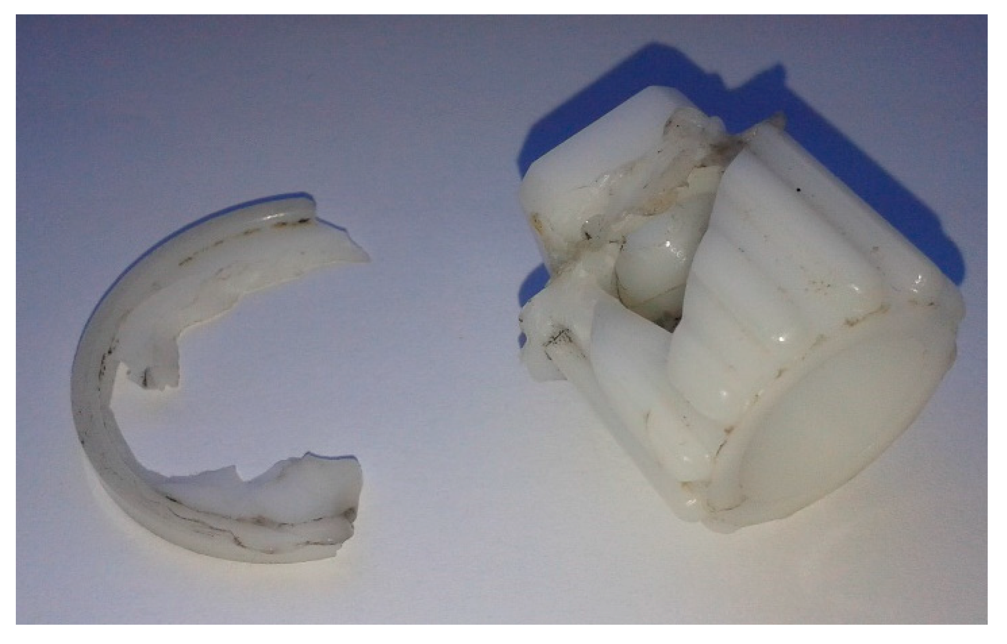
Figure 2.
The execution sketch of the grooved shaft [3].
Figure 2.
The execution sketch of the grooved shaft [3].

Figure 3.
Cilindrical lathe of the semi-couple

Figure 4.
Measurement of deviations of fixing the part in the universal of the index head of FUS 22 machine tool: measuring the radial beat (a); axial deviation out of the X direction measurement (b); measuring frontal beat (c); axial deviation out of the Y direction measurement (d); Three-dimensional (3D) model of the slotting machine process: main cutting movement (I), indexing movement, executed by the part (II); mortising device (1) mortising knife-tool (2), part (3), screw for fixing the knife-tool (4).

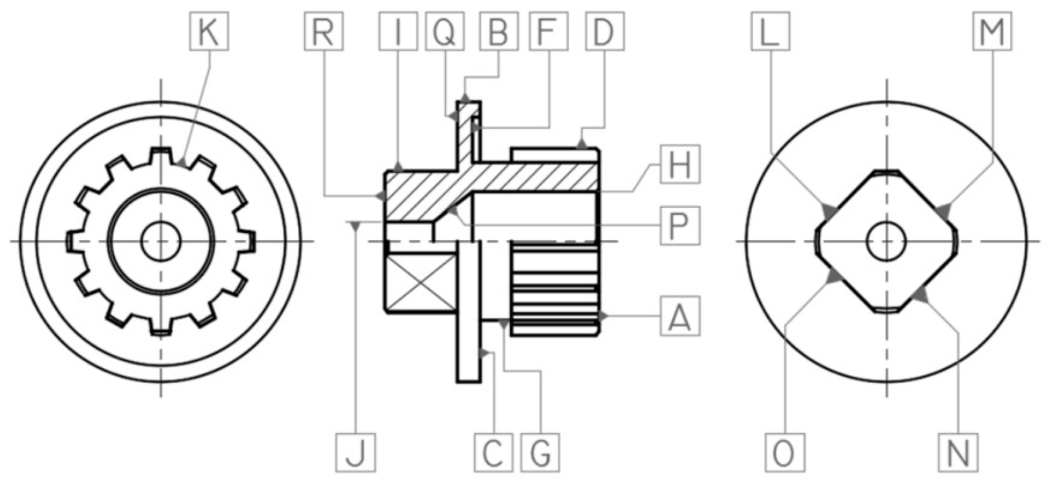
Figure 6.
Shape evolution at the mortise knife manufacture.

Figure 7.
Geometric and constructive elements of the radial slotting tool and holder bar for cutting tool [3,15].
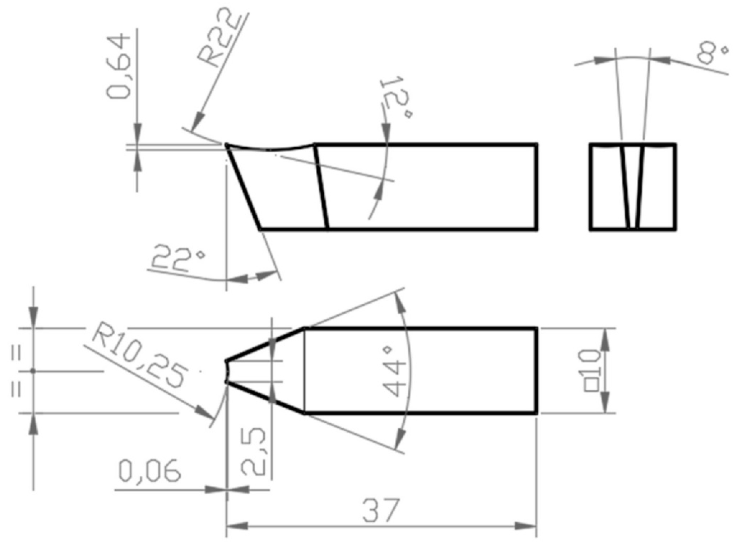
Figure 8.
Slotting the groove (a), cutting the piece (b) and milling the square profile (c).

Figure 9.
The piece after mortising (a), in four hypostases—the finished piece (b), the part-mounted piece on the worm (c).
Figure 9.
The piece after mortising (a), in four hypostases—the finished piece (b), the part-mounted piece on the worm (c).

Table 1.
The coefficient of linear expansion [4].
Table 1.
The coefficient of linear expansion [4].
| Characteristic Properties | M.U. | Metal | Nylon 6.6 | ||||
|---|---|---|---|---|---|---|---|
| Steel | Al | Mg | Monowire | 30% Fiberglass | 30% Carbonfiber | ||
| The coefficient of linear expansion | 10−6/K | 14 | 22 | 25 | 80 | 30 | 20 |
Publisher’s Note: MDPI stays neutral with regard to jurisdictional claims in published maps and institutional affiliations. |
© 2021 by the authors. Licensee MDPI, Basel, Switzerland. This article is an open access article distributed under the terms and conditions of the Creative Commons Attribution (CC BY) license (http://creativecommons.org/licenses/by/4.0/).
Share and Cite
MDPI and ACS Style
Bucur, B.; Bucur, C.; Andronic, G. Peculiarities Regarding the Reconstruction of a Broken Grooved Shaft. Proceedings 2020, 63, 65. https://0-doi-org.brum.beds.ac.uk/10.3390/proceedings2020063065
AMA Style
Bucur B, Bucur C, Andronic G. Peculiarities Regarding the Reconstruction of a Broken Grooved Shaft. Proceedings. 2020; 63(1):65. https://0-doi-org.brum.beds.ac.uk/10.3390/proceedings2020063065
Chicago/Turabian StyleBucur, Bogdan, Constantin Bucur, and Gabriela Andronic. 2020. "Peculiarities Regarding the Reconstruction of a Broken Grooved Shaft" Proceedings 63, no. 1: 65. https://0-doi-org.brum.beds.ac.uk/10.3390/proceedings2020063065