RPAS Automatic ADS-B Based Separation Assurance and Collision Avoidance System Real-Time Simulation Results


Air Transport Sustainability Department, CIRA, Italian Aerospace Research Centre, 81043 Capua, Italy
*
Author to whom correspondence should be addressed.
Drones 2020, 4(4), 73; https://0-doi-org.brum.beds.ac.uk/10.3390/drones4040073
Submission received: 9 October 2020
/
Revised: 29 November 2020
/
Accepted: 3 December 2020
/
Published: 7 December 2020
Abstract
:Remotely piloted aircraft systems (RPAS) are increasingly becoming relevant actors that are flying through the airspace and will gain much more importance in the future. In order to allow for their safe integration with manned conventional traffic in non-segregated airspaces, in accordance with the overall air traffic management (ATM) paradigm, specific enabling technologies are needed. As is well known, the detect and avoid (DAA) technology is fundamental among the enabling technologies identified as crucial for RPAS integration into the overall ATM system. In the meantime, to support extended surveillance, the universal introduction of cooperative automatic dependent surveillance-broadcast (ADS-B) on-board aircraft is being increasingly implemented because it has the potential to allow for the coverage of the entire airspaces in remote areas not usually covered by conventional radar surveillance. In this paper, experimental results that were obtained through the real-time validation, with hardware and human in the loop (RTS-HIL) simulations, of an automatic ADS-B based separation assurance and collision avoidance system aimed to support RPAS automatic operations (as well as remote pilot decision making) are presented and discussed. In the paper, after an introductory outline of the concept of operations (ConOps) of the system and its architectural organization, in addition to basic information about the main system functionalities, a description of the tests that were carried out is reported, and the obtained results are described and discussed in order to emphasize the performance and limitations of the proposed system. In particular, the obtained quantitative performances are reported and commented on, and the feedback presented by pilots in order to improve the system, e.g., in terms of preferred typology of conflict resolution maneuver elaborated by the system, is described.
1. Introduction
In the last few decades, remotely piloted aircraft systems (RPAS) have emerged as relevant and increasingly diffused new actors in air traffic, covering flights that range from very low-level operations to higher flight levels. The first appearance of RPAS was in the military framework due to the inherent advantages deriving from the use of unmanned aerial vehicles (UAVs) in dangerous operations in threat environments. Advantages such as the possibility to use the full range of the performance of the platform, the lack of humans on board, and the reduced costs associated with mission execution including risk for human pilots, motivated significant efforts towards the development of military RPAS [1]. After that, RPAS also started to be considered in the civilian aviation framework with the aim of achieving similar advantages in civil applications in terms of costs reduction and the substitution of human pilots in performing repetitive tasks and long endurance operations that can be efficiently delegated to automation in aircraft guidance. In addition, the parallel development of concepts such as the ones of small air transport (SAT) [2] and personal air transport system (PATS) [3] is linked to RPAS concepts and technologies.
The SAT concept is now addressed in terms of the research and development of solutions allowing for single pilot operations that have the potential to ease the introduction of this aviation transport paradigm as a relevant industry, especially, for instance, in areas of Europe where surface transport infrastructures are not extensively implemented enough and the costs for implementation would be excessively high due to the presence of geographical barriers. In such a situation, a solution to increase mobility capabilities would be to implement the extensive use of regional small airports, which are numerous in those areas, by wide number of SAT vehicles that would be piloted under single pilot operations to reduce flight costs and the needed number of qualified crew. In such a framework, research activities are ongoing under the transversal SAT work package in the Clean Sky 2 EU-funded program, including activities specifically devoted to design of enabling technologies for single pilot operations in SAT vehicles that are carried out in the Cost Optimized Avionic System (COAST) project [4,5]. In this framework, in order to reduce the single pilot workload, detect and avoid technologies are fundamental and also more relevant in the case of the delegation of the separation responsibility to the flight segment, as envisaged under specific circumstances by the SESAR (Single European Sky ATM Research) air traffic management (ATM) Target Concept [6]. Based on that, specific design activities are ongoing in the COAST project addressing an automatic dependent surveillance-broadcast (ADS-B)-based tactical separation system supporting the pilot in the separation task [7,8] and a step forward in terms of the design of an overall integrated mission management system that automatically enables flight, including self-separation tasks, in the case of pilot incapacitation [9]. It is clear that these technologies represent a cross fertilization of the detect and avoid (DAA) technologies coming from the RPAS domain and the unmanned vehicle automation domain in general.
Therefore, the PATS approach, which is intended to be implemented in this new and revolutionizing aviation sector, targets the total autonomy of the vehicles in cases of both freight and passenger transport, thus motivating dedicated efforts addressing the design of technologies such as ones for 4D automatic navigation, situation assessment and supervision, swarms guidance, separation assurance and collision detection, fault detection, and isolation [10]. For this aim, RPAS technologies play a fundamental role as the baseline for cross fertilization and further improvement of full autonomy in the PATS domain. Additionally, a fundamental role is played, once again, by DAA technologies.
Even if the RPAS domain is very relevant in terms of both current application and future further developments, as outlined above, the presence of such new actors in the airspace has led to a new and very important issue in terms of safety: the safe integration of RPAS with conventional manned vehicles in the common airspace. This issue becomes more relevant in view of the expected activation of the urban air mobility (UAM) transport segment, which will probably start by using conventional rotorcraft with conventional pilots and will then evolve through the RPAS paradigm towards fully automated vehicles for passenger (and freight of course) transport into wide urban areas over the next few years or decades. This suggests a double issue in terms of safety: (1) the integration of RPAS with conventional manned traffic in usual airspaces without using segregation while being under the control of conventional ATM and air traffic control (ATC) systems; (2) integration of the RPAS and, from the perspective of UAM vehicles, into an overall ecosystem devoted to unmanned traffic management (UTM) in the lower airspace (very low level (VLL) operations) ecosystem that is now being designed and implemented according to the U-Space paradigm [11].
A considerable number of research and development activities aimed at supporting and allowing for the integration of RPAS in the unsegregated airspace have been undertaken worldwide in the last few decades. In Europe, for instance, the INOUI (Innovative Operational UAV Integration) and ICONUS (Initial ConOps for UAS in SESAR) projects were carried out as the first ones addressing the issue. The findings of ICONUS [12] indicated that there are several classes of obstacles for RPAS integration in the unsegregated airspace: regulatory obstacles, such as common standards, interoperability, and airworthiness; procedural obstacles, namely the planning of operations, separation methods and minima, approach procedures, and emergency procedures; social and organizational issues, namely human factors, public acceptance, and liability insurance; and system limitations, notably the detect and avoid system, the command and control link, and the safety, security, and reliability aspects linked to those systems. Further complication have arisen due to the large number of RPAS types, as well as the dimension and the variability of missions. RPAS can range from few grams (and the further reduction of weight is a clear trend) to vehicles that can weigh as much as general aviation aircraft; missions can vary from usually scheduled to unscheduled flights. Depending on such a large number of issues, widespread initiatives have been conducted all over the word, often in a non-coordinated fashion.
Based on that, in Europe, the SESAR program has devoted efforts to support the integration of RPAS together with conventional manned vehicles in the non-segregated airspace. Starting from the roadmap for the integration of RPAS prepared by the European RPAS Steering Group (ERSTG) [13], the SESAR Joint Undertaking (SJU) completed the RPAS Integration Definition Phase, which identified the guidelines for the RPAS integration topic to be included in the SESAR2020 program, thus driving the R&D development in ATM in Europe in these years. Consequently, SJU sponsored dedicated projects under the global program for RPAS Demos in order to investigate and collect data from flight tests and experiences about RPAS integration issues. One of such projects was the RAID (RPAS-ATM Integration Demonstration), which carried out both real-time validations and flight demonstrations for the integration of RPAS vehicles in ATM. A description of the real-time demonstrations carried out in RAID was provided in [14], which aimed to represent an overview of the project contents but was not specifically devoted to the specification of the features of the DAA system that was tested in the project, i.e., the integrated ADS-B-based automatic separation assurance collision avoidance system (ASACAS) designed by CIRA, the Italian Aerospace Research Center. ASACAS is the specific name (acronym) of the CIRA DAA-designed system integrating both emergency collision avoidance and tactical separation assurance functionalities, as well as TCAS (Traffic Collision Avoidance System) compatibility checks and advanced situational awareness functionalities, into a unique system under unique mission automation logic that is able to manage a unique system that integrates both separation assurance (acting in a time horizon of up to 2–3 min) and collision avoidance (acting in time horizon of lower than 1 min) with a unique software system. For this reason, the CIRA-designed DAA system has been denoted the specific name of the “automatic separation assurance and collision avoidance system” and the specific corresponding acronym ASACAS.
The aim of this paper was to therefore report on the outcomes and findings from the real-time demonstrations carried out in the RAID project with more detail and a more specific focus, thus complementing and extending the previous reference paper [14]. The novel contribution of this paper is in the fact that it specifically focuses on the DAA system (i.e., the ASACAS designed by CIRA), whereas the previous paper [14] included the DAA system as one aspect of a wider paper addressing a description of the RAID project and the overall real-time simulation campaigns carried out therein. This led to the need to address the ASACAS aspects only in part in [14], whereas in this paper, the ASACAS is the focus of the paper, including therefore aspects not considered in [14], mainly including the background and motivations leading to the design of the system (Section 2.1), the system of the concept of operations (Section 2.2), a high-level description of the implemented functionalities and algorithms (Section 2.4 and all related subsections), and the presentation of further test cases and related results (Section 3). Of course, being limited to real-time demonstration results description and discussion, this paper does not cover flight demonstration results, which will be addressed in future works.
The paper is organized as follows. Section 2 first reports a description of the applicable CIRA background and motivations that led to the design of the integrated ADS-B-based automatic separation assurance collision avoidance system. Then, it provides an overview of the system concept of operation and of the implemented system architecture while also providing basic information about the algorithms implemented in the main system functionalities. Section 3 then describes the real-time simulation environment and some relevant tests that have been performed in such real-time simulations, with reference to both collision avoidance and separation assurance experiments, including the related test plan and the obtained results. Finally, Section 4 reports the conclusion of the paper.
2. Materials and Methods
2.1. Background and Motivations
In the last few decades, CIRA has gained relevant expertise in the design of DAA systems thanks to activities that have been carried out in both nationally-funded Italian projects and in internationally-funded European projects.
The integrated ADS-B-based automatic separation assurance collision avoidance system, whose real-time simulation campaign is the subject of this paper, is indeed the result of many years of incremental research on this topic. The main motivation that led the design of such a system was the capitalization and extension of previous experience related to single baseline systems for collision avoidance (radar-based) and self-separation in order to achieve the design of a unique, integrated system managing all functions at the same time according to properly designed overall system automation logic and the implementation of the above-mentioned functions in the most appropriate way while considering the requirements of compliance with the rules of the air [15] and self-compatibility.
Here, the evolutionary approach that led to the ASACAS design is outlined. A baseline version of an autonomous collision avoidance radar-based system was developed in the framework of the nationally-funded Italian project TECVOL (Technologies for Autonomous Flight), reaching TRL (Technology Readiness Level) 6 as an individual technology [16,17,18,19]. The baseline version of an ADS-B-based separation assurance system was developed in the framework of the Italian project SEPARA (System for General Aviation Separation Support), reaching TRL 5 as an individual technology [20,21].
Starting from these baseline individual systems, in the nationally-funded Italian project MISE (Applications for Unmanned Aircraft Avionics), the first and baseline version of the ADS-B-based integrated ASACAS was developed. The first version of the ASACAS then evolved in the nationally-funded Italian project EATS (Efficient Air Transport System). The second (evolved) version of the system was then demonstrated, both in real-time and real live flight trials, in the SJU-funded project RAID, which was completed in 2016 and achieved TRL 6.
In more detail, ASACAS development was implemented through the incremental steps described as follows. The first version of the ASACAS (version 1p0) was designed in order to update the former autonomous collision avoidance (ACA) system developed in the framework of the project TECVOL. The rationale of this update was the need to adapt the collision avoidance functionality to the use of the ADS-B IN cooperative surveillance sensor as unique sensor for obstacle detection purposes, thus replacing the radar-based non-cooperative sensor suite used in the application developed in TECVOL. This represented the first step towards the development of a fully integrated automatic separation assurance and collision avoidance system (ASACAS version 2p0), including both separation assurance and collision avoidance functionalities based on the ADS-B IN surveillance sensor, as well as the integration of a dedicated situational awareness functionality and overall ASACAS logic. The ADS-B IN-provided surveillance data are used as input for conflict and collision detection algorithms in order to support the collision avoidance and the separation assurance functionalities.
In ASACAS 1p0, the collision detection system for collision avoidance was specifically modified with respect to the former TECVOL application [16,17,18,19] and designed in order to allow it to use ADS-B IN-provided data that are broadcast by all ADS-B OUT-equipped surrounding aircraft. The overall collision detection system architecture designed in ASACAS 1p0 aimed to manage the ADS-B data in order to provide the collision avoidance resolution algorithm (which has not been changed from the baseline version) with proper information about surrounding traffic [22,23]. In this phase, another dedicated surveillance processing application that is compliant with applicable RTCA (Radio Technical Commission for Aeronautics) standard DO-317 [24] was designed and implemented.
ASACAS 2p0 improved the collision avoidance functionality that was already implemented in ASACAS version 1p0, and it designed and integrated the functionalities of separation assurance (modifying and evolving the baseline self-separation functionality from SEPARA [20,21]), TCAS compatibility check, and situational awareness. Moreover, ASACAS 2p0 included suitable automation logic that was specifically developed to properly manage the behavior of the whole integrated system.
The ASACAS therefore provides the RPAS with the following automatic capabilities:
- Assistance to separation assurance to perform a separation maneuver when required to remain well clear of other traffic aircraft.
- Collision avoidance.
- Enhanced situational awareness, providing traffic information to allow the RPAS pilot to build their situational awareness related to the surrounding traffic as an enhancement of the remote pilot traffic supervision.
- Provision of compatibility information between the ASACAS and the TCAS operations in the case of proximity between the ownship and a TCAS-equipped aircraft.
- Provision of an automation logic that coordinates and sequences all the functionalities, based on the risk associated with the surrounding aircraft, and processes the possible remote pilot inputs received through the dedicated human–machine interface (HMI) implemented in the remote pilot station (RPS).
Further improvements of the ASACAS are still ongoing in the framework of the EATS project [25,26], benefitting from the additional experience and know-how gained by CIRA in several international projects both completed (e.g., the EDA-funded project MIDCAS: Mid-Air Collision Avoidance System [27,28]) and currently ongoing (e.g., the Clean Sky 2-funded project COAST [4,5,7,8]). Such improvements were focused on the improvement of the algorithms for detection and resolution and not on any change of the sensor for traffic detection, which remains the ADS-B IN to address cooperative traffic detection. Other works that make use of different sensors are available in literature, including papers vision-based intruder detection systems [29], but the consideration of such systems is not foreseen as a future extension of ASACAS, at least for the time being and the near future.
2.2. Concept of Operations
Based on what is indicated above, three main capabilities are provided by ASACAS implementation: separation assurance (SA), collision avoidance (CA) and situational awareness (SitA). Here, we provide a description of the interactions between the system and the RPAS remote pilot in order to outline the ASACAS’s intended application and benefits.
The RPAS remote pilot is aware of traffic information by means of an HMI that allows them to build their situational awareness related to the surrounding traffic, including the indication of the consolidated traffic tactical picture around the remotely piloted aircraft (ownship) and the associated level of severity of each surrounding aircraft in terms of loss of separation and collision risk with respect to the ownship. To consolidate the traffic picture and evaluate the associated risks, the system uses ADS-B IN-provided inputs, as well as ownship navigation data provided by the onboard navigation sensor (GPS, Global Positioning System). The overall ASACAS concept of operations is represented in Figure 1, where ATC indicates the air traffic control service provision facility, GCC is the RPAS ground control station where the remote piloted vehicle station is located, and FCC indicates the flight control computer hosting the on-board ASACAS software (as well as the additionally needed software for autopilot and low-level aircraft control).
From an operational point of view, the ASACAS continuously performs the monitoring of traffic in order to provide an enhanced situational awareness to the remote pilot and to identify a possible loss of separation and/or collision risks.
In the presence of a predicted loss of separation with respect to one or more traffic vehicles, the system is expected to provide information and automatically elaborate a separation recovery maneuver to the remote pilot. The remote pilot is then in charge of evaluating the feasibility of the maneuver with respect to the constraints affecting the flight and not considered by the ASACAS (it is worth noticing that the system performs the elaboration of the separation recovery maneuver without considering any constraint related to, for instance, existing no-fly zones, segregated areas, fixed obstacles, or flight plan constraints). If needed, based on the current tactical picture, the remote pilot can interact with the ATCo (air traffic controller) in order to ask for clearance for the implementation of the proposed maneuver or to negotiate it. Based on the outcomes of the remote pilot and/or ATCo evaluations, the maneuver can be accepted, and, in this case, the remote pilot can decide to delegate its automatic implementation to the aircraft autopilot or to implement the maneuver themself.
In the presence of a predicted risk of collision with respect to one or more surrounding traffic vehicles, the ASACAS is expected to provide information to the remote pilot and to automatically elaborate collision avoidance maneuver with respect to the most dangerous vehicle, according to the proper prioritization criterion. The collision avoidance maneuver, due to its emergency nature, is expected to be automatically implemented by the automatic guidance system. Nevertheless, the remote pilot is provided with the possibility of aborting the maneuver and taking the direct control of the vehicle at any moment.
The ASACAS is also continuously performing a TCAS compatibility check that is aimed to provide a prediction, based on the current trajectory of the ownship and traffic vehicles, of the resolution advisory activation in the surrounding traffic vehicles equipped with TCAS [30]. Based on the outcome of this check, the expected behavior of the ASACAS with respect to the identified loss of separation and collision risks is accordingly modified in order to ensure that no maneuvers are generated by the ASACAS that could create nuisances to the TCAS-elaborated maneuver.
The ASACAS evaluates the situation in real time at a cycle frequency (ASACAS runs at 1 Hz), so it updates the maneuver suggested to the pilot continuously, which means that if the pilot waits too much and the suggested maneuver is no longer applicable, it is automatically substituted by the ASACAS with a new applicable maneuver.
The “latency” is referred to the overall time that is needed for the reception of traffic info by the ADS-B IN for processing by the ASACAS and the elaboration of the suggested maneuver, as well as the time needed for the maneuver evaluation by the remote pilot and implementation. In general, the latency contribution due to the ASACAS’s computation time is much lower (1 s usually when working at 1 Hz because in all the performed real-time simulations, the system was demonstrated to be able to provide a maneuver in 1 s) than the time needed by the pilot for evaluation and implementation. Considering that the human-related time is a variable not predictable, the ASACAS was designed to automatically perform continuous updates of maneuvers, as indicated above, so that the proposed maneuvers is immediately substituted with a new one when the old is no longer applicable, therefore overcoming the problem of a possible long evaluation time by the remote pilot. This concept is also applied after the clearance and implementation of the maneuver by the remote pilot because the current situation is always evaluated by the ASACAS at cycle frequency (1 Hz) during the flight—even during the maneuver execution—in order to be able to provide a new maneuver when needed.
2.3. Architecture
As outlined in the previous sections, the ASACAS includes the functionalities of SA and CA, and it provides an enhanced SitA to the remote pilot by classifying each surrounding vehicle based on the associated risk with respect to the ownship. The SA and CA functions are allocated to two different logical levels, since CA is considered an emergency function that is activated only when an emergency event is raised, whereas the SA function is in charge of guaranteeing safe separation among aircraft in tactical operations. The functional architecture of the ASACAS is reported in Figure 2 [14].
As indicated in Figure 2, the system receives traffic position and velocity data about surrounding ADS-B OUT-equipped aircraft from the on-board ADS-B IN surveillance sensor in order to predict future conflicts (intended as a predicted loss of separation) and potential future collisions between the ownship and surrounding traffic. The DAA system is supported by a DO-317 [24] surveillance processing application that is used to perform the processing of the raw data provided by the ADS-B IN surveillance system in order to allow for their use by the conflict/collision detection system. Furthermore, the functional architecture comprises the following functionalities, which are outlined in the following section:
- Coarse filtering for both the collision avoidance and separation assurance functions.
- Conflict detection for the separation assurance function.
- Conflict resolution for the separation assurance function.
- Collision detection for the collision avoidance function.
- Collision prioritization for the collision avoidance function.
- Collision resolution for the collision avoidance function.
- TCAS compatibility check for the situational awareness function.
- Severity assignment for the situational awareness function.
- ASACAS logic.
The outputs of the system include the classification of the surrounding traffic in terms of conflicts (i.e., vehicles that constitute a potential loss of separation with respect to the ownship), threats (i.e., vehicles that constitute a collision risk with respect to the ownship), and traffic (i.e., vehicles that do not pose risks with respect to the ownship). Furthermore, the DAA system elaborates a suitable maneuver to restore the separation minima with respect to all the detected conflicts (if any) and a suitable maneuver to escape from the most dangerous collision vehicle detected (if any). The separation assurance maneuver is proposed to the remote pilot, who is in charge of providing his/her clearance and may also request the automatic implementation of the maneuver by the system. The collision avoidance maneuver is executed in an automatic way due to the emergency nature of such a maneuver and can be terminated by the remote pilot if needed.
2.4. Algorithms
A detailed description of the algorithms applied in the ASACAS and of the related implementation in the dedicated functionalities beyond the scope of this paper, which is focused on real-time test description. Nevertheless, in order to aid the comprehension of the system behavior, a conceptual description of each ASACAS function and, therefore, of the associated implemented algorithms is reported. Some details about the baseline versions of the collision avoidance individual algorithm and regarding the baseline version of the separation assurance individual algorithm can be found in the reference papers [16,17,18,19,20,21], respectively. As already described, these baseline versions have evolved the integration into the overall designed ASACAS, as outlined in Section 2.1.
For the specific application in the real-time testing addressed in this paper, it is worth emphasizing here that the considered separation volume is a cylinder centered in the conflicting intruder, the planar radius of which is 0.5 Nm and the semi-height of which is 500 ft. The size of the cylinder is properly incremented in order to consider the uncertainties mainly affecting the position and velocity data of the intruder. The considered collision volume, then, is a sphere centered in the colliding intruder with a 500 ft radius. The radius of the sphere is properly incremented in order to consider the uncertainties mainly affecting the position and velocity data of the intruder.
2.4.1. SA and CA Coarse Filtering
In order to provide a pre-selection of the traffic, due to the ADS-B IN equipment’s capability of detecting traffic located very far away and therefore a priori not representing a risk for the ownship, a suitable coarse filtering function is needed to select the surrounding aircraft to be processed by the CA and SA functionalities, thus reducing the computational burden. The basic principle proposed for coarse filtering consists of excluding the aircraft whose distance from the ownship is greater than a specified threshold from the conflict/collision detection. The thresholds set for conflict and collision detection should be different due to the different natures of risk associated with SA and CA functionalities. Therefore, two different coarse filtering systems were implemented, one for each functionality.
2.4.2. SA Conflict Detection
After receiving traffic information about aircraft resulting from SA coarse filtering processing, the conflict detection function checks for a potential loss of separation between the ownship and each considered aircraft. The conflict detection is based on the calculation of possible breach of the cylindrical separation volume by the ownship with respect to all the surrounding traffic vehicles: a pair-wise check is implemented for each and all the surrounding traffic vehicles that have been provided by the dedicated SA coarse filtering functionality, and the cylindrical separation volume breach is considered only if occurring within the specified tactical time horizon considered for separation assurance by the ASACAS. The output of this functionality is a list of conflicting vehicles with associated conflict geometry data. For the separation assurance functionality, a suitable safety bubble, also referred as a “protected zone,” is defined. This represents a non-intrusion zone around a traffic aircraft where the ASACAS declares that action is needed to preclude the ownship from going into the volume associated with separation minima.
The ASACAS’s separation assurance functionality is implemented as the tactical capability of keeping the RPAS vehicle away from other airborne aircraft by at least the separation minima defined by Eurocontrol as follows [31]: “Specification RPA11: Where an RPA pilot is responsible for separation, he should, except for aerodrome operations, maintain a minimum distance of 0.5 NM horizontally or 500 ft vertically between his RPA and other airspace users, regardless of how the conflicting traffic was detected and irrespective of whether or not he was prompted by a Sense and Avoid system”. Based on such approach, the separation assurance protected zone implemented by the ASACAS is a cylindrical volume of airspace centered on the aircraft, with a horizontal radius of 0.5 NM and a vertical height of 500 ft, as represented in Figure 3.
In addition to such separation assurance volume nominal dimensions, suitable extra-sizes are considered due to the uncertainties affecting sensor measurements and aircraft maneuvering. These additional extra-sizes are obtained by means of an incremental sizing factor that increases separation volume dimensions according to the closure rate between the conflicting aircraft. Therefore, the protected airspace zone is obtained as the sum of the nominal (minimum) size and the closure rate-dependent calculated extra-size, resulting in a variable overall size due to the variable closure rate between the considered aircraft.
2.4.3. SA Conflict Resolution
The conflict resolution function is activated once one or more conflicting aircraft have been identified by the conflict detection function, and, therefore, a separation maneuver is automatically elaborated by this function, thus assuring the ownship separation from all the aircraft detected as conflicts. The function, therefore, calculates multi-conflict separation maneuver that aims to avoid cylindrical separation volume infringement for the considered conflict geometry while using separation and the proper prioritization of the channels (longitudinal, lateral, and speed) in which the maneuver is proposed in order to not generate excessive workload for the pilot in evaluating and implementing the maneuver.
In addition, in order to allow for the integration of the proposed system in regular conventional traffic and to inherently guarantee self-compatibility among aircraft equipped with the ASACAS SA functionality, the maneuver is elaborated in such a way as to comply with the rules of the air.
Furthermore, the maneuver is elaborated in such a way to be able to resolve all the conflict encounters detected by the conflict detection function while avoiding the insurgence of new conflicts as a consequence of the maneuver itself, thus ensuring the minimum deviation from the ownship nominal trajectory.
As anticipated above, the conflict resolution maneuver is elaborated according to three different possible strategies, with tuning priority as follows: horizontal resolution maneuver, vertical resolution maneuver, and velocity resolution maneuver. The horizontal resolution maneuver is a planar maneuver based on the modification of the current ownship’s track angle; the suggested track angle aimed to resolve the conflict situation is computed in order to avoid a breach of the separation volume while considering the airspace sector from which the conflicting intruder is coming and the applicable right of way. The vertical resolution maneuver is based on the modification of the current ownship’s height to avoid breaching the separation volume around the conflicting aircraft while maintaining the track angle. The speed resolution maneuver is calculated to avoid the separation volume breach by only changing the speed magnitude of the ownship. Finally, as a last resort, a full inertial speed vector variation maneuver, consisting of a whole inertial velocity vector modification, is computed if the previous individual ones cannot solve the conflict. The calculated separation maneuver is then suggested to the pilot on the HMI.
The separation assurance maneuver is considered to be completed when the condition of clear of conflict (CoC) is satisfied, as stated below:
- No infringement of the assigned separation volumes is detected for any considered vehicle
AND
- Ownship distance with respect to all the considered conflicting vehicles is increasing.
If the separation assurance maneuver was automatically executed (the remote pilot can command the automatic maneuver execution or can execute it manually as he/she prefers), once these conditions are met, the ownship automatically returns to the original course by implementing the automatic capture of the next applicable waypoint (WP) on the flight plan. Otherwise, if the maneuver was executed in manual or in semi-automatic modes, the responsibility of managing the vehicle once cleared of conflict is that of the remote pilot, who is made aware of the clear of conflict through the dedicated symbols on the interfaces.
2.4.4. CA Collision Detection
After receiving traffic information about aircraft of interest as resulting from the CA coarse filtering processing, the collision detection function checks for potential collision conditions between the ownship and each considered aircraft. The collision detection is based on the calculation of possible breach of spherical collision volume by the ownship with respect to all the surrounding traffic vehicles: a pair-wise check is implemented for each and all the surrounding traffic vehicles that are provided by the dedicated CA coarse filtering functionality, and the collision volume breach is considered only if occurring within the specified emergency time horizon (greater than the tactical time horizon of the SA functionality) that is considered the collision avoidance look ahead time by the ASACAS. The output of this functionality is a list of potentially colliding vehicles with associated collision geometry relevant data.
For the collision avoidance functionality, a suitable safety bubble that is smaller than the separation assurance volume is considered. Based on the near mid-air collision definition by the Federal Aviation Administration (FAA) [32], which refers to the possibility of collision during an encounter in which the aircraft are within 500 ft of each other, the safety volume for the collision avoidance functionality implemented by the ASACAS is a spherical volume of airspace centered on the aircraft with a radius of 500 ft, as represented in Figure 4, where the relation with the separation assurance volume is also indicated, even if not in scale.
In addition to such collision avoidance volume nominal dimensions, a suitable extra-size is applied due to the uncertainties affecting sensor measurements and aircraft maneuvering. This additional extra-size is obtained by means of an incremental sizing factor that increases collision volume dimensions according to the closure rate between the ownship and the involved threat. Therefore, the collision avoidance safety volume is obtained as a sum of the nominal (minimum) size and the closure rate-dependent calculated extra-size, resulting in a variable overall size due to the variable closure rate between the considered aircraft.
2.4.5. CA Collision Prioritization
Based on the check performed by the collision detection function, multiple collisions may be detected, i.e., more than one surrounding aircraft may pose a threat to the ownship. Therefore a dedicated prioritization criterion is proposed in order to individuate the most dangerous collision risk. To perform the prioritization, the most relevant collision geometry parameters are considered, and particular importance is given to the resulting time-to-go (i.e., the range over range rate ratio between the considered aircraft).
2.4.6. CA Collision Resolution
The collision resolution function shall elaborate a modification of RPAS vehicle trajectory that is aimed to avoid the predicted collision with respect to the only threat aircraft considered the highest priority by the prioritization logic. The function, therefore, elaborates a single-collision avoidance maneuver that is aimed to prevent the spherical collision volume infringement for the considered collision geometry. The maneuver does not implement any separation and prioritization of the channels (longitudinal, lateral, and speed), as it is inherently calculated as a 4D maneuver. Of course, based on the specific collision geometry, the elaborated maneuver may only affect one of the control channels (e.g., a purely collision avoidance maneuver can be elaborated), but this is not pre-determined or selected by specific design of the functionality and is purely determined by the collision geometry among the available 4D maneuvers. It is also worth noticing that, due to the emergency nature of the maneuver, it does not consider any requirement in terms of the rules of the air.
Due to the single-threat consideration approach, it is clear that, even when the collision detection has detected more threat aircraft, only one threat at a time is considered by the collision resolution. This is managed by the collision prioritization function that identifies the most dangerous threat aircraft as a priority. Once this collision threat is solved, a new one can be sequentially solved—but not simultaneously.
If the TCAS compatibility check identifies that the threat vehicle is equipped with TCAS and is triggering a resolution advisory (RA), a suitable logic is in charge of inhibiting the automatic execution of the ASACAS collision resolution maneuver in order to not interfere with the TCAS; this is a piece of industrially certified equipment that has priority over the ASACAS collision avoidance functionality. On the other hand, if the threat aircraft is detected as not equipped with TCAS or it is equipped but the TCAS is not expected to activate RAs, the ASACAS collision resolution maneuver is automatically implemented by the ownship. In this case, the remote pilot is only able to abort the automatic collision avoidance maneuver through dedicated command inputs available through the HMI if he/she wants.
The collision avoidance maneuver is considered as completed when the condition of clear of collision is satisfied, as described below:
- No infringement of the assigned collision volume is detected for the considered threat.
AND
- Ownship distance with respect to the considered threat is increasing.
Once these conditions are met, the ownship can return to the original course by implementing the automatic capture of the next applicable waypoint on the flight plan.
2.4.7. TCAS Compatibility Check
In order to manage the compatibility of the ASACAS implemented in the ownship with the potential TCAS-equipped surrounding aircraft, the TCAS compatibility check function predicts when one or more of them will trigger a RA due to the ownship’s proximity. This information allows for the guarantee of the compatibility between the ASACAS and the TCAS, because based on the predicted RA-alerted aircraft, the expected behavior of the ASACAS with respect to the identified loss of separation and collision risks is accordingly modified in order to ensure that no nuisance maneuvers are generated by ASACAS that disturb the TCAS maneuver elaborated by the considered traffic vehicle.
2.4.8. Severity Assignment
The severity assignment function bases its elaboration on the data provided by the SA and CA functions in order to support the remote pilot by means of visual depiction on a dedicated cockpit display of traffic information (CDTI) system for the whole traffic scenario. Once all the aircraft have been processed by the CA and SA functions, all the detected surrounding aircraft are managed and classified based on:
- The conflict status provided by the conflict detection function.
- The collision status provided by the collision detection function and suitably prioritized by the collision prioritization one.
- The RA alerted status provided by the TCAS compatibility check function.
For this aim, the severity assignment function identifies which is/are the surrounding aircraft with respect to whether a separation or collision avoidance maneuver is needed while also considering the RA-alerted aircraft. From a practical point of view, the severity assignment functionality-provided output is the data source for visualization on a dedicated display implemented on the HMI of all the relevant information related to the surrounding traffic, collected and elaborated by the CA and SA functions and suitably classified and prioritized according to the associated severity level of risk, in order to individuate and differentiate all the aircraft represented on the CDTI system.
2.4.9. ASACAS Logic
The assignment of a severity risk to each surrounding aircraft is processed by a suitable ASACAS logic in order to establish the ASACAS’s operational status. The ASACAS logic function processes the information about the aircraft detected as conflicts/collisions and those ones provided by the TCAS compatibility check in order to:
- Coordinate and sequence the two functionalities of separation assurance and collision avoidance, based on the risk associated to the surrounding aircraft.
- Process the remote pilot commands to the ASACAS (for instance, separation assurance or collision avoidance maneuver termination) issued through the HMI.
3. Results and Discussion
3.1. Real-Time with Harware and Humans in the Loop Simulation Environment and Test Methodology
The paper addresses the description of very complete and accurate real-time with hardware and humans (pilot and controller) in the loop simulations performed in a complex laboratory environment [14]. The figures reported here were generated (using MATLAB) in the post-flight data analysis by processing the real-time simulation data that were stored in the flight data recorder used in the laboratory environment.
The aircraft model was a very accurate, complete 6DoF (6 Degrees of Freedom) model. In addition, atmospheric disturbances replicating real flight, as well as traffic, were considered in the overall simulation environment, which connects the ownship 6DoF simulator, the traffic simulator, and the outside world (atmospheric) simulator in the same framework. In addition, the ATCo instructions were provided in real-time by real air traffic controllers using their controller working positions (CWPs) connected to the real-time simulation environment. Finally, the remote pilot was a real human pilot commanding the ownship with a dedicated RPS, by means of which the pilot could guide the ownship in augmented mode or using the real autopilot panel implemented in the RPS that was installed in the real-time laboratory environment.
What follows is a description of the overall environment used for the real-time simulations (RTS).
The primary components of the RTS laboratory environment were:
- The remote pilot station emulator.
- The RTS simulator of the RPAS vehicle, which embedded the detect and avoid system (i.e., the ASACAS described in this paper) and the ADS-B equipment simulator.
- The ATCo working positions simulator, including multiple CWPs to simulate aerodrome control, terminal control, and en-route control operations.
- A scenario, environment, and traffic simulator, specifically for intruder (manned or unmanned) aircraft and commercial aircraft normally flying inside the Malta airspace that were considered for the RTS campaign.
Additional components of the RTS laboratory environment were:
- An engineering working station, for data recordings.
- The secondary pilot position for safety (on-board) pilot operations such as the hand-over maneuver (the hand-over (H-O) of the RPAS control from the safety pilot to the remote pilot was carried out to simulate in real-time the handover procedure needed in the real world live flight tests for the execution of the flight: the safety pilot is the one onboard the CIRA optionally-piloted aircraft named FLARE (Flying Laboratory for Aeronautical Research) and is in charge of conducting the flight up to the assigned test airspace; once inside the assigned test airspace, the OPA FLARE is remotely controlled by the remote pilot, thus making it an RPAS. Such a transfer of control is executed in the H-O waypoint).
To ensure the highest level of the meaningfulness of the results of the simulations, both pilots and controllers operated in their usual operating environments. The RPS, the RTS, and the safety pilot position emulator were located on the CIRA premises in Italy, while the simulated controller working positions were realized on the MATS (Malta Air Traffic Services) premises in Malta. The scenario simulator was shared between the CIRA and MATS premises: MATS fed the real-time simulations with commercial traffic, while CIRA simulated the intruders, both manned and unmanned, that were used for the separation assurance and collision avoidance tests.
The remote pilot station was an exact reproduction of the actual remote pilot station used for the CIRA Optionally Piloted Vehicle, as shown in Figure 5 [14].
The HMI of the ATCo working position emulator, as used on the MATS premises, is reported in Figure 6 [14].
The RTS simulator was a high-fidelity simulator of the FLARE experimental vehicle that reproduced the dynamics of a TECNAM P92 Echo-S vehicle at a high accuracy level by integrating many different piloting modes:
- Manual, in which the simulator acts as if the aerodynamic control surfaces are directly maneuvered by the pilot.
- Augmented, in which the pilot’s commands, in terms of attitudes rates, are sent to a stability and augmentation flight control system.
- Autopilot mode, in which the pilot’s commands, in terms of select and hold commands on relevant flight path variables (e.g., altitude, velocity, and track) are sent to a flight control computer (FCC) that operates as an autopilot.
- The flight plan mode, in which a series of waypoints are uploaded by the pilot and the FCC defines and executes maneuvers to follow the sequence of WPs.
The scenario simulator was shared between the CIRA and MATS premises. Traffic aircraft not directly involved in the separation assurance and collision avoidance tests were also included in the simulations to allow ATCos to also require traffic vehicles to operate under their instructions (to simulate proper ATCo workload during the separation assurance and collision avoidance tests).
The scenario simulator embedded a GPS constellation simulator, which allowed one to send GPS-simulated data to the ADS-B simulator. The ADS-B traffic data were sent both to the RPS in order to be visualized on the pilot’s CDTI system and to the ASACAS, also embedded in the simulator, which was the actual system aimed to be implemented in the vehicle FCC for the expected live flight trials after completing the RTS campaign.
Finally, a safety pilot position that reproduced the TECNAM P92 cockpit instrument allocation in a very simple way, was used. The engineering working station completed the set-up: from the engineering working position, different non-nominal conditions, such as GPS signal spoofing and the C2L (Command and Control Link) jamming, could be activated.
All the vehicle data and events were recorded in the FDR (Flight Data Recorder) embedded in the EWS (Engineering Workstation).
All the RTS environment components were connected for data and voice communications. A synchronized virtual private network (VPN) on an Ethernet connection were established between the CIRA and MATS premises, allowing for the synchronized real-time interaction of all the simulated elements. Voice communication was again ensured by the Ethernet connection, using proprietary or freeware communications software.
As far as the involved professionals are concerned, at least a professional pilot and two professional controllers were involved in each scenario simulation. In the most complex scenario, two pilots and two air traffic controllers—the remote pilot, the safety pilot, the aerodrome controller, and the terminal maneuvering area (TMA) controller—were simultaneously involved in all scenarios in which the hand-over maneuver was reproduced.
A total amount of about 50 real-time simulations, involving pilots and controllers as described before, were carried out in two test campaigns. All the scenarios were simulated in different operating conditions. Nominal and non-nominal conditions were tested with various possible levels of surrounding traffic, encounter conditions, and malfunctions of the systems. Many data files were recorded:
- Time-histories for all the position-velocity variables of the aircraft involved in the simulations.
- Log files for trajectory and housekeeping data for the RPAS under test.
- Audio/video recordings of the whole test sessions, both at the CIRA premises and the MATS premises.
- Questionnaires submitted and filled by the pilots and controllers during de-briefing sessions.
3.2. Test Plan
Three exemplary tests of the RTS campaigns are detailed as follows:
- Test 1: Separation assurance automatically implemented by the DAA system once having received proper clearance by the remote pilot.
- Tests 2 and 3: Collision avoidance automatically implemented by the DAA system.
In all the tests, the ownship was flying inside a defined operational maneuvering area in the presence of multiple vehicles as surrounding traffic, and one of these represented a conflict (i.e., potential loss of separation) in test 1 and a threat (i.e., potential collision) in tests 2 and 3.
In the description of all the RTSs, only the vehicle of interest is represented in the figures of this paper, even if other traffic was also simulated and managed by the ATCo during the RTS. The intruder and ownship positions were reported with respect to a local reference frame centered in the initial position of the ownship at the simulation start. In the real-time tests described here, conventionally, the origin of the local reference frame corresponded to the point where the handover procedure between the safety pilot and the remote pilot was completed; therefore, the remote pilot was operating the RPAS ownship [14].
The test cases reported here aim to illustrate the behavior of the ASACAS functionalities during real-time tests, with specific reference to the exemplary situations considering the different involved ASACAS functionalities in different traffic geometries, as summarized in Table 1.
3.2.1. Test 1 Plan
The initial conditions for the ownship and intruder of interest are shown in Figure 7 and reported in Table 2.
Both aircraft performed straight and level flight towards their selected destination WPs, so the geometry considered here led to a loss of separation according to head-on encounter (it can be noticed that, indeed, a lateral displacement of 500 m existed between the vehicles, which led to the loss of separation condition in all cases due to the circumstance that the nominal separation volume centered in the intruder had a 0.5 Nm radius, which was greater than the 500 m displacement).
3.2.2. Test 2 Plan
The initial conditions for the ownship and intruder of interest are shown in Figure 8 and reported in Table 3.
Both aircraft performed straight and level flight towards their selected destination waypoints, so the geometry considered here led to a loss of separation and then to a collision condition, according to a beam encounter, while the ownship moved from WP2 to WP3.
It is worth noticing that, in order to allow for the activation of the collision avoidance functionality, the maneuver proposed by the separation assurance functionality was voluntarily ignored by the remote pilot, thus allowing for the ownship RPAS to continue its flight plan until the distance threshold set for the activation of the collision avoidance functionality was reached.
3.2.3. Test 3 Plan
The initial conditions for the ownship and intruder of interest are shown in Figure 9 and reported in Table 4.
Both aircraft performed straight and level flight towards their selected destination waypoints, so the geometry considered here led to a loss of separation and then to a collision condition, according to head-on encounter, while the ownship moved towards WP1. It is worth noticing that, in order to allow for the activation of the collision avoidance functionality, the maneuver proposed by the separation assurance functionality was voluntarily ignored by the remote pilot, thus allowing for the ownship RPAS to continue its flight plan until the distance threshold set for the activation of the collision avoidance functionality was reached.
3.3. Test Results
Next, the results of the tests whose plan is detailed in Section 3.1 are reported and discussed in order to provide indications and examples of the ASACAS’s performance and limitations.
3.3.1. Test 1 Results
When the distance threshold set for the activation of the separation assurance function was reached, the system indicated to the remote pilot the predicted loss of separation condition; at the same time, it started proposing a suitable separation assurance maneuver to be implemented by the ownship. The remote pilot, after having analyzed the proposed maneuver (that was updated at a proper rate by the ASACAS), provided his clearance for the activation and, in this specific test, requested the automatic implementation of the maneuver by the autopilot, i.e., requested ASACAS to automatically send the separation assurance maneuver reference commands to the autopilot. The separation assurance maneuver for this head-on encounter geometry consisted of a track variation of about 25 degrees, as represented in Figure 10.
This led to a trajectory of the ownship (the conflicting intruder continued its straight-levelled flight undisturbed) that was tangent to the separation volume centered in the intruder and whose size was increased with respect to the nominal one based on the closure rate between vehicles at the moment where the maneuver was frozen by the system. The ownship trajectory represented in Figure 10 did not seem to be tangent to the separation volume due to the unavailability of some real-time trajectory data that were not correctly saved in the flight data recorder and thus not retrieved in the post flight data analysis, leading to the need for the offline computation of the separation volume dimensions with some approximation. Indeed, it is worth noticing here that the separation assurance maneuver was the one cleared by the remote pilot; nevertheless, some fine tuning of it was still possible and automatically implemented by the ASACAS during the maneuver execution if needed based on the current traffic picture.
In Figure 11, the range distance r and the range rate r dot between the two aircraft involved in the conflict situation are reported. It is worth noticing here that the range and range rate indicated in Figure 11 were only calculated during the separation assurance maneuver execution, i.e., from about 62 to about 268 s, and the null values indicated outside this time interval therefore have no meaning in the figure. An analysis of Figure 11 then, allows one to observe that, in this real-time simulation test, the conflict condition was detected by the ASACAS at about 32 s, and so the self-separation maneuver started to be proposed to the pilot few moments after that time (due to elaboration time and transmission latency). The remote pilot examined the maneuvers that were updated in real-time by the system at a proper frequency and, at about 62 s, cleared the automatic execution of the proposed maneuver by the system.
The minimum distance between vehicles (i.e., the distance at the closest point of approach—CPA) was set to about 1800 m, consistent with the set dimension of the separation volume. Thus, the ownship trajectory was almost tangent to the separation volume. The separation assurance maneuver was completed at about 268 s, when the range rate between vehicles became positive (the vehicles started diverging).
The separation assurance functionality of the ASACAS, therefore, was shown to perform as expected in the real-time simulation test described here.
3.3.2. Test 2 Results
When the distance threshold set for the activation of the ASACAS collision avoidance function was reached, the DAA system indicated the predicted collision condition to the remote pilot and automatically started to execute a suitable collision avoidance maneuver, thus allowing the ownship to avoid the collision. The remote pilot monitored the collision avoidance maneuver executed by the system, and they had the possibility to abort it and take the control of the RPAS if desired.
The collision avoidance maneuver for this beam encounter geometry led to a 3D variation of the ownship trajectory that resulted in a modified trajectory tangent to the collision safety volume centered on the intruder. The collision safety volume size was increased with respect to the nominal one based on the closure rate between vehicles at the moment where the collision avoidance maneuver was elaborated by the system. It is worth noticing here that the collision avoidance maneuver could be automatically updated by the DAA system during its execution if needed based on the current traffic picture. The updates of the maneuver are indicated by the signal “collision detection” rising to 1 in Figure 13, whereas the implementation of the maneuver is indicated by the “CA maneuver” signal maintained at level 1 in the same figure.
An analysis of Figure 13, then, allows one to observe that, in this real-time simulation test, the collision condition was detected by the ASACAS at about 3670 s, and the collision avoidance maneuver simultaneously started to be automatically executed by the system (after the proper, very small elaboration time).
The minimum distance between vehicles (i.e., the distance at the CPA) was about 240 m. The collision avoidance maneuver was completed at about 3730 s, when the range rate between vehicles became positive (the vehicles started diverging). As already indicated in the previous tests, the range and range rate were calculated only during the collision avoidance functionality execution; therefore, the null values indicated outside this time interval have no meaning in the figure.
The collision avoidance functionality of the ASACAS, therefore, was shown to perform as expected in the real-time simulation test described here.
3.3.3. Test 3 Results
When the distance threshold set for the activation of the ASACAS collision avoidance function was reached, the DAA system indicated the predicted collision condition to the remote pilot and automatically started executing a suitable collision avoidance maneuver that allowed the ownship to avoid the collision. The remote pilot monitored the collision avoidance maneuver executed by the system, and they had the ability to abort it and take the control of the RPAS if desired.
The collision avoidance maneuver for this head-on encounter geometry led to a 3D variation of the ownship’s trajectory (the colliding intruder continued its straight-levelled flight undisturbed) that resulted in it being tangent to the collision volume centered in the intruder and whose size was increased with respect to the nominal one based on the closure rate between vehicles at the moment where the collision avoidance maneuver was elaborated by the ASACAS. As already indicated, the collision avoidance maneuver could be automatically updated by the DAA system during its execution if needed based on the current traffic picture. The updates of the maneuver are indicated by the signal “collision detection” rising to 1 in Figure 15, whereas the implementation of the maneuver is indicated by the “CA maneuver” signal being maintained at level 1 in the same figure.
An analysis of Figure 15 allows one to observe that in this real-time simulation test, the collision condition was detected by the DAA system at about 465 s, and, at the same time, the collision avoidance maneuver started to be automatically executed by the system (after the proper, very small elaboration time) through the automatic transmission of the maneuver reference commands to the aircraft autopilot.
The minimum distance between vehicles (i.e., the distance at the CPA) was about 460 m, consistent with the set dimension of the collision volume; thus, the ownship’s trajectory was tangent to the collision volume. The collision avoidance maneuver was completed at about 515 s, when the range rate between vehicles became positive (the vehicles started diverging). As in the previous tests, the indicated range and range rate were only calculated during the collision avoidance functionality execution, so the null values indicated outside this time interval have no meaning in the figure.
The collision avoidance functionality of the ASACAS, therefore, was shown to perform as expected in the real-time simulation test described here.
4. Conclusions
The paper reported some exemplary experimental results obtained through real-time validation, with hardware and human in the loop (RTS-HIL) simulations of an automatic ADS-B-based separation assurance and collision avoidance system (ASACAS) aimed to support RPAS automatic operations and remote pilot decision making. The paper described the background, motivation, and design steps that led to the development, implementation, and testing of the ASACAS. In addition, the paper provided a description of the concept of operations of the system and of its architectural organization, and it summarized the main concepts implemented in the system, identifying its main functions and their mutual connection in the overall integrated system.
From the description of the exemplary real-time simulation with hardware and pilots in the loop tests (including both separation assurance and collision avoidance test scenarios) and from the analysis and discussion of the related results, it emerged that the ASACAS behaved as expected in the tests: it was demonstrated to be able to support the remote pilot in performing the separation management task at a tactical level and to be able to perform automatic collision avoidance at the emergency level.
The elaborated maneuvers, both for self-separation and for collision avoidance, were able to minimize the deviation from the original flight path while also being able to prevent an infringement of the assigned safety volumes.
The self-separation maneuver was designed according to early feedback and suggestions provided by the very experienced test pilots that acted as remote pilots. In particular, the separation assurance functionality of the ASACAS was designed to provide maneuvers that preferably act on only one flight dimension (longitudinal, lateral, or speed), with an assigned priority to lateral changes (track deviation)—a priority that is, in all cases, a parameter that can be set as desired. This design choice changed the initial implementation of the functionality, where the design was aimed to obtain 4D maneuver, and was motivated by the need to provide the pilot with a minimum amount of workload in evaluating and implementing the proposed maneuver. From such perspective, it is much more convenient for the pilot to manage a suggested maneuver that only affects one flight dimension than a whole 4D maneuver. Therefore, the conflict resolution functionality assigns specified priority to the possible resolution maneuvers in order to select the one that minimizes the workload for the remote pilot; when this is not possible due to a particular conflict scenario, the system increases the maneuver complexity up to a full 4D maneuver. This is a relevant added value of the system.
Future work will address many possible improvements of the system. It is currently designed to be used in the en-route phase of a flight, and its extension to TMA operations is a future improvement of the system. In addition, the collision avoidance functionality of the system is limited to sequential single-collision management and does not specifically take into account the rules of the air and self-compatibility requirements. Therefore, future improvements will be needed to address these important aspects.
Finally, as indicated in the introductory part of the paper, the system has also been validated in real flight trials that will be the subject of future publications.
Author Contributions
Both authors contributed extensively to the research activities presented in this paper. V.D.V. prepared and reviewed all sections of the paper, G.T. specifically prepared Section 3.2 and Section 3.3. All authors have read and agreed to the published version of the manuscript.
Funding
The real-time simulation campaigns described in this paper were co-financed by the SESAR Joint Undertaking through the project RAID, as part of RPAS Demo projects of the SESAR Program. The ASACAS design was carried out in the framework of the nationally-funded Italian projects MISE and EATS.
Acknowledgments
The real-time simulation activities, whose exemplary results are reported in this paper, were carried out in the framework of the RAID project, co-financed by the SESAR Joint Undertaking as part of RPAS Demo projects of the SESAR Program. The ASACAS design was carried out in the framework of the nationally-funded Italian projects MISE and EATS. The opinions expressed in this work reflect the authors’ views only.
Conflicts of Interest
The authors declare no conflict of interest.
References
- Glade, D. Unmanned Aerial Vehicles: Implications for Military Operations. Occasional Paper No. 16; Center for Strategy and Technology Air War College, Air University, Maxwell Air Force Base: Maxwell, AL, USA, 2000. [Google Scholar]
- Viken, S.A.; Brooks, F.M.; Johnson, S.C. Overview of the Small Aircraft Transportation System Project Four Enabling Operating Capabilities. J. Aircr. 2006, 43, 6. [Google Scholar] [CrossRef] [Green Version]
- PPLANE. The Personal Plane Project, VII European Commission Framework Program. Available online: http://www.pplane-project.org/ (accessed on 2 October 2020).
- Di Vito, V.; Mercogliano, P.; Beran, J.; Sapakova, M.; Maslowski, P.; Grzybowski, P.; Rogalski, T. Selected Avionic Technologies in the COAST project for Small Air Transport Vehicles. In Proceedings of the 7th EASN International Conference on Innovation in European Aeronautics Research, Warsaw, Poland, 26–29 September 2017. [Google Scholar]
- Di Vito, V.; Beran, J.; Kabrt, T.; Grzybowski, P.; Rogalski, T.; Maslowski, P.; Montesarchio, M. Flight management enabling technologies for single pilot operations in Small Air Transport vehicles in the COAST project. In Proceedings of the 10th EASN Virtual International Conference on Innovation in Aviation & Space to the Satisfaction of the European Citizens, Salerno, Italy, 2–4 September 2020. [Google Scholar]
- SESAR Consortium. D3-The ATM Target Concept. SESAR Definition Phase–Deliverable 3. DLM-0612-001-02-00a; SESAR Consortium: Brussels, Belgium, 2007. [Google Scholar]
- Di Vito, V.; Torrano, G.; Beran, J. A Tactical Separation System for Small Air Transport Vehicles. In Proceedings of the 7th EASN International Conference on Innovation in European Aeronautics Research, Warsaw, Poland, 26–29 September 2017. [Google Scholar]
- Di Vito, V.; Torrano, G.; Cerasuolo, G.; Ferrucci, M. Tactical Separation System for Small Air Transport Vehicles: Design advancements in the COAST Project. In Proceedings of the 10th EASN Virtual International Conference on Innovation in Aviation & Space to the Satisfaction of the European Citizens, Salerno, Italy, 2–4 September 2020. [Google Scholar]
- Di Vito, V.; Grzybowski, P.; Rogalski, T.; Masłowski, P. A concept for an Integrated Mission Management System for Small Air Transport Vehicles in the COAST project. In Proceedings of the 10th EASN Virtual International Conference on Innovation in Aviation & Space to the Satisfaction of the European Citizens, Salerno, Italy, 2–4 September 2020. [Google Scholar]
- Di Vito, V.; Gabard, J.-F.; Filippone, E.; Morani, G.; Le Tallec, C.; Giulietti, F.; Gatti, M.; Keshales, B.; Greenberg, S.; Delic, M.; et al. Automation and Control Architectures for the Personal Plane Project. In Proceedings of the AUVSI Israel International Conference, Tel Aviv, Israel, 20–22 March 2012. [Google Scholar]
- CORUS Consortium. U-Space Concept of Operations. Deliverable D6.3. CORUS Consortium, 2019. Available online: https://www.sesarju.eu/sites/default/files/documents/u-space/CORUS%20ConOps%20vol2.pdf (accessed on 5 December 2020).
- ICONUS Consortium. Initial Concept of Operation for UAS in SESAR. Deliverable D-B2, ICONUS Consortium, 2012.
- European RPAS Steering Group. Roadmap for the integration of civil Remotely-Piloted Aircraft Systems into the European Aviation System. Final Report. European RPAS Steering Group, 2013. Available online: http://ec.europa.eu/DocsRoom/documents/10484/attachments/1/translations/ (accessed on 5 December 2020).
- Filippone, E.; Di Vito, V.; Torrano, G.; Taurino, D.; Ferreira, A.; Zammit-Mangion, D.; Gauci, J.; Gargiulo, G. RPAS–ATM Integration Demonstration–Real-Time Simulation Results. In Proceedings of the AIAA International Air Safety Summit, IASS 2015, Miami, FL, USA, 2–4 November 2015. [Google Scholar]
- ICAO. Rules of the Air. Annex 2 to the Convention on International Civil Aviation, 10th ed. 2005. Available online: https://www.icao.int/Meetings/anconf12/Document%20Archive/an02_cons%5B1%5D.pdf (accessed on 5 December 2020).
- Fasano, G.; Accardo, D.; Moccia, A.; Carbone, C.; Ciniglio, U.; Corraro, F.; Luongo, S. Multi-sensor based fully autonomous non-cooperative collision avoidance system for unmanned air vehicles. AIAA J. Aerosp. Comput. Inf. Commun. 2008, 5, 338–360. [Google Scholar] [CrossRef]
- Luongo, S.; Di Vito, V.; Fasano, G.; Accardo, D.; Forlenza, L.; Moccia, A. Automatic Collision Avoidance System: Design, Development and Flight Tests. In Proceedings of the 30th Digital Avionics Systems Conference, DASC 2011, Seattle, WA, USA, 16–20 October 2011. [Google Scholar]
- Fasano, G.; Accardo, D.; Forlenza, L.; Moccia, A.; Luongo, S.; Di Vito, V. Flight Demonstration of Radar-based Autonomous Non-cooperative UAS Collision Avoidance. In Proceedings of the 3rd CEAS Air&Space Conference, 21st AIDAA Congress, CEAS 2011 the International Conference of the European Aerospace Societies, Venice, Italy, 24–28 October 2011. [Google Scholar]
- Fasano, G.; Accardo, D.; Moccia, A.; Luongo, S.; Di Vito, V. In-flight performance analysis of a non-cooperative radar-based sense and avoid system. Proc. Inst. Mech. Eng. Part G J. Aerosp. Eng. 2016, 230. [Google Scholar] [CrossRef] [Green Version]
- Luongo, S.; Di Vito, V.; Corraro, F. An Advanced 3D Algorithm for Automatic Separation Assurance Systems. MED 2012. In Proceedings of the 20th Mediterranean Conference on Control & Automation, Barcelona, Spain, 3–6 July 2012. [Google Scholar]
- Di Vito, V.; Luongo, S.; Torrano, G.; Garbarino, L.; Corraro, F.; Filippone, E. Real-Time Pilot Support System for Airborne Self-Separation. ISIATM 2013. In Proceedings of the 2nd International Conference on Interdisciplinary Science for Innovative Air Traffic Management, Toulouse, France, 8–10 July 2013. [Google Scholar]
- Orefice, M.; Di Vito, V.; Corraro, F.; Fasano, G.; Accardo, D. Aircraft Conflict Detection Based on ADS-B Surveillance Data. In Proceedings of the IEEE Metrology for Aerospace Conference, Benevento, Italy, 29–30 May 2014. [Google Scholar]
- Orefice, M.; Di Vito, V.; Garbarino, L.; Corraro, F.; Fasano, G.; Accardo, D. Real-Time Validation of an ADS-B Based Aircraft Conflict Detection System. In Proceedings of the Infotech@Aerospace 2014 Conference, Kissimmee, FL, USA, 5–9 January 2015. [Google Scholar]
- RTCA. Minimum Operational Performance Standards (MOPS) For Aircraft Surveillance Applications (ASA) System. DO-317A; RTCA: Washington, DC, USA, 2011. [Google Scholar]
- Orefice, M.; Di Vito, V. An innovative algorithm for 2D Collision Avoidance manoeuvers elaboration based on spiral trajectories. In Proceedings of the 17th AIAA Aviation Technology, Integration, and Operations Conference, Denver, CO, USA, 5–9 June 2017. [Google Scholar]
- Orefice, M.; Di Vito, V. Aircraft Automatic Collision Avoidance Using Spiral Geometric Approach. In Proceedings of the International Conference on Aerospace Sciences and Aviation Technology, ICASAT 2016, Lisbon, Portugal, 14–15 April 2016. [Google Scholar]
- Pellebergs, J. The MIDCAS project. In Proceedings of the 27th International Congress of the Aeronautical Sciences, ICAS, Stockholm, Sweden, 19–24 September 2010; pp. 3241–3247. [Google Scholar]
- Alfredson, J.; Hagström, P.; Sundqvist, B.-G. Situation awareness for mid-air detect-and-avoid system for remotely piloted aircraft. Procedia Manuf. 2015, 3, 1014–1021. [Google Scholar] [CrossRef] [Green Version]
- Rzucidło, P.; Rogalski, T.; Jaromi, G.; Kordos, D.; Szczerba, P.; Paw, A. Simulation studies of a vision intruder detection system. Aircr. Eng. Aerosp. Technol. 2020, 4, 621–631. [Google Scholar] [CrossRef]
- U.S. Department of Transportation. Federal Aviation Administration (FAA). Introduction to TCAS II. Version 7.1; U.S. Department of Transportation: Washington, DC, USA, 2011.
- EUROCONTROL. Specification SPEC-0102. EUROCONTROL Specification for the Use of Military Unmanned Aerial Vehicles as Operational Air Traffic Outside Segregated Airspace; EUROCONTROL: Brussels, Belgium, 2007. [Google Scholar]
- FAA. Aeronautical Information Manual–Official Guide to Basic Flight Information and ATC Procedures; FAA: Washington, DC, USA, 2006.
Figure 1.
Automatic separation assurance collision avoidance system (ASACAS) concept of operations. ATC: air traffic control service provision facility; GCC: remotely piloted aircraft systems (RPAS) ground control station; FCC: flight control computer; ADS-B: automatic dependent surveillance-broadcast.

Figure 2.
ASACAS functional architecture [14]. SA: separation assurance; HMI: human–machine interface; CA: collision avoidance.
Figure 2.
ASACAS functional architecture [14]. SA: separation assurance; HMI: human–machine interface; CA: collision avoidance.

Figure 3.
ASACAS nominal separation assurance volume.

Figure 4.
ASACAS nominal collision avoidance volume (represented with respect to the separation assurance volume, which is not in scale).
Figure 4.
ASACAS nominal collision avoidance volume (represented with respect to the separation assurance volume, which is not in scale).

Figure 5.
Remote pilot station (RPS) and pilot’s HMI detail in the real-time simulation (RTS) environment [14].
Figure 5.
Remote pilot station (RPS) and pilot’s HMI detail in the real-time simulation (RTS) environment [14].

Figure 6.
Air traffic controller (ATCo) simulated working position [14].
Figure 6.
Air traffic controller (ATCo) simulated working position [14].

Figure 7.
Test 1: starting positions in local reference frame.

Figure 8.
Test 2: starting positions in local reference frame.

Figure 9.
Test 3: starting positions in local reference frame.

Figure 10.
Test 1: automatic separation assurance maneuver showing the 3D trajectory of the ownship and conflicting intruder.
Figure 10.
Test 1: automatic separation assurance maneuver showing the 3D trajectory of the ownship and conflicting intruder.

Figure 11.
Test 1: automatic separation assurance maneuver and parameters of interest.

Figure 12.
Test 2: automatic collision avoidance maneuver showing the 3D trajectory of the ownship and conflicting intruder.
Figure 12.
Test 2: automatic collision avoidance maneuver showing the 3D trajectory of the ownship and conflicting intruder.

Figure 13.
Test 2: automatic collision avoidance maneuver and parameters of interest.

Figure 14.
Test 3: automatic collision avoidance maneuver showing the 3D trajectory of the ownship and colliding intruder.
Figure 14.
Test 3: automatic collision avoidance maneuver showing the 3D trajectory of the ownship and colliding intruder.

Figure 15.
Test 3: automatic collision avoidance maneuver and parameters of interest.


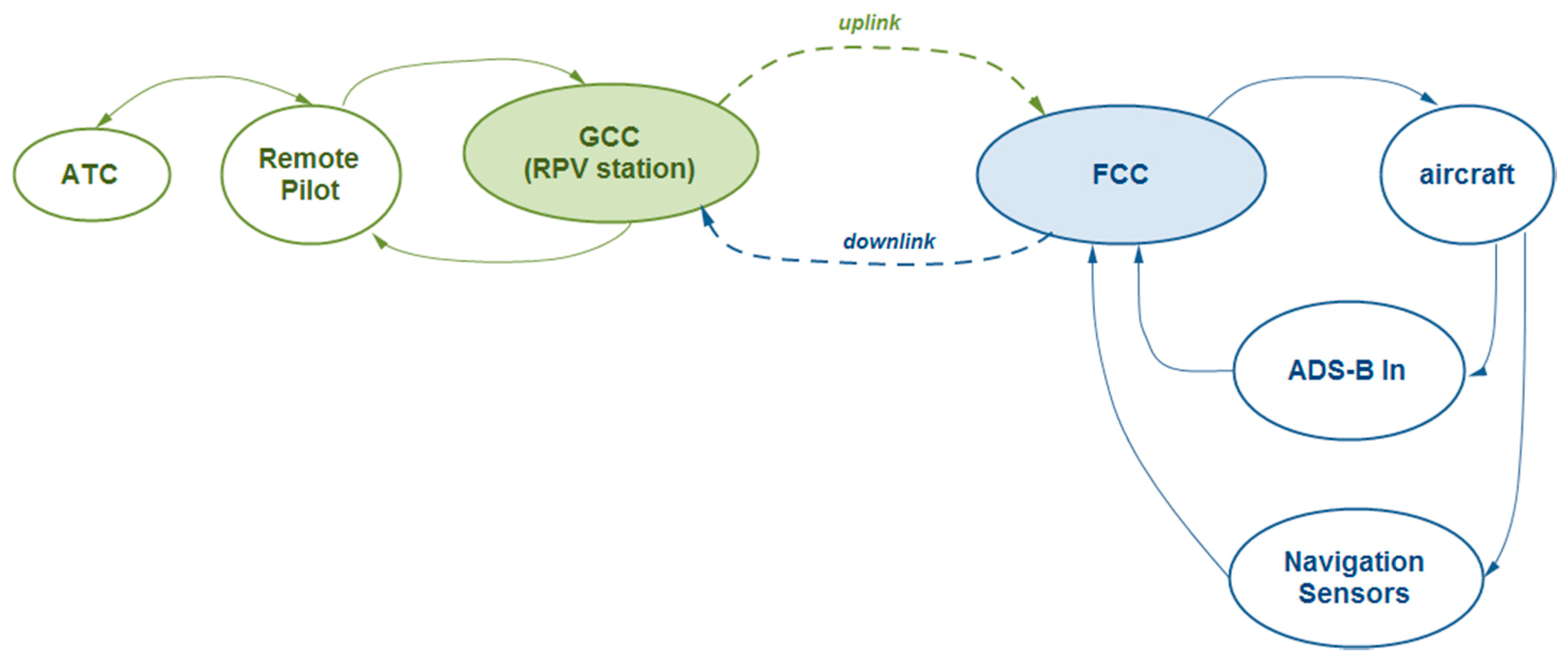
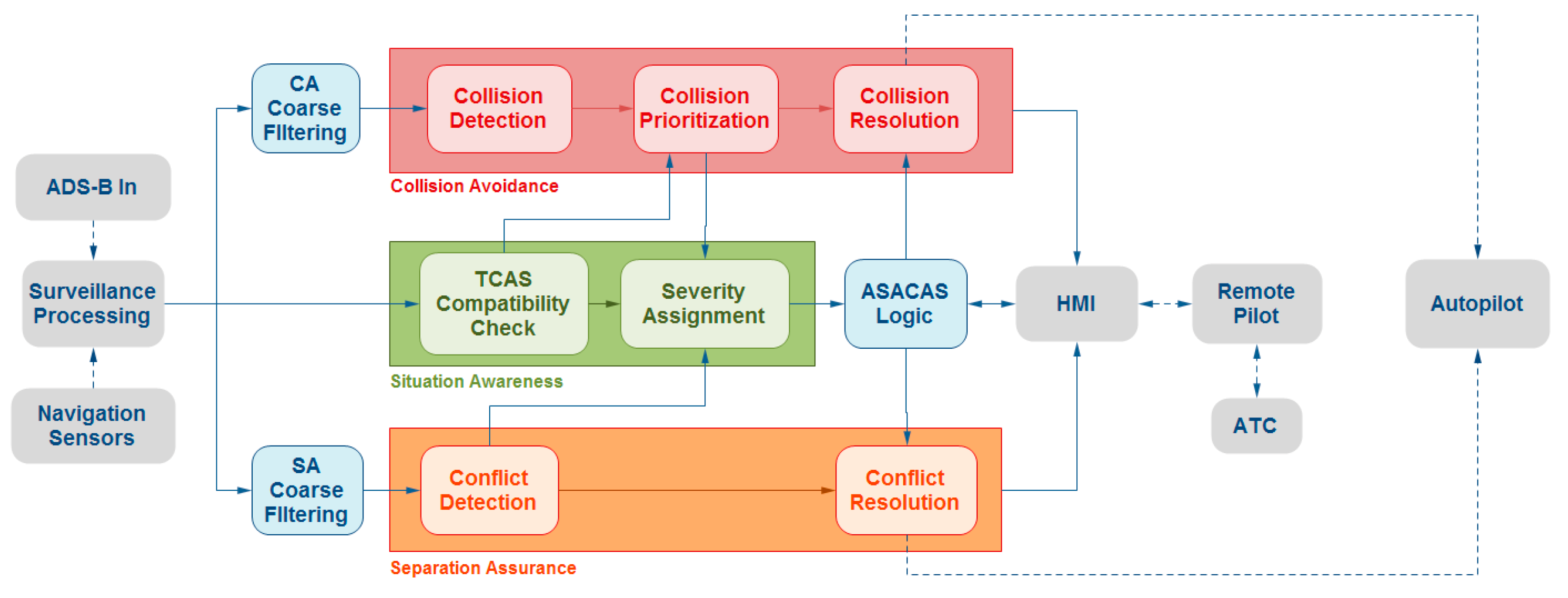
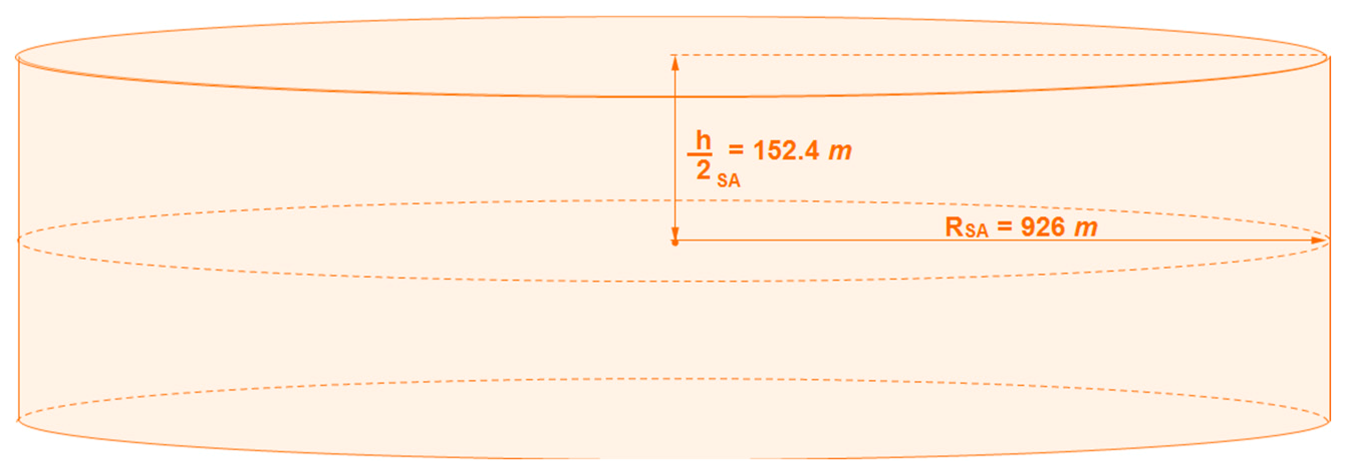
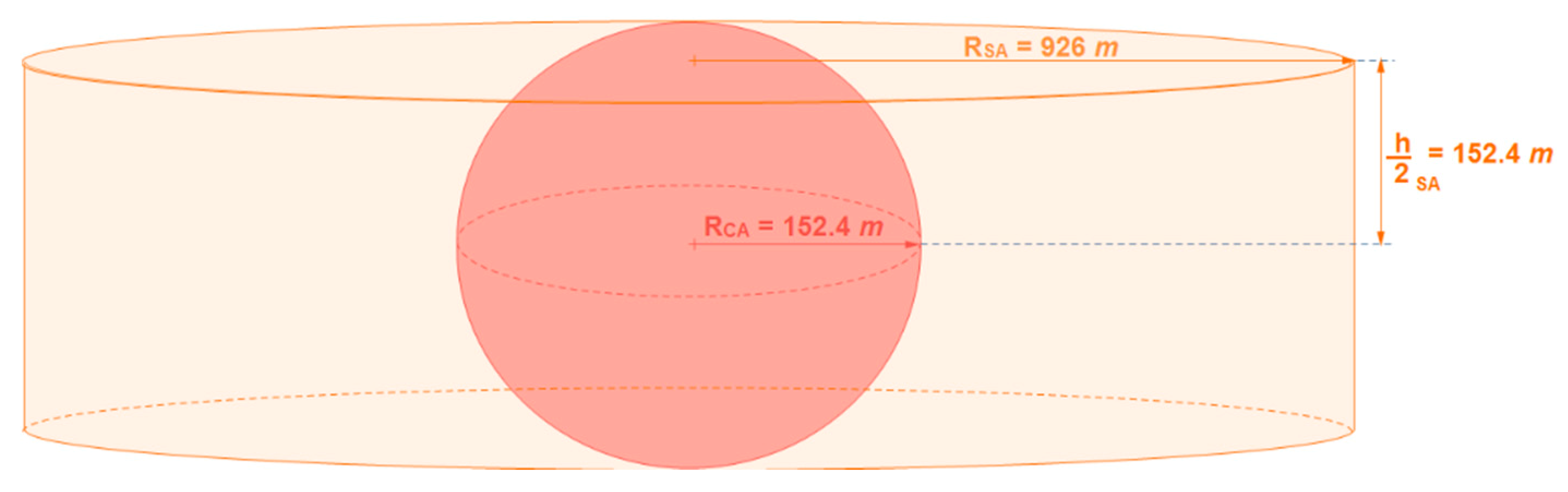
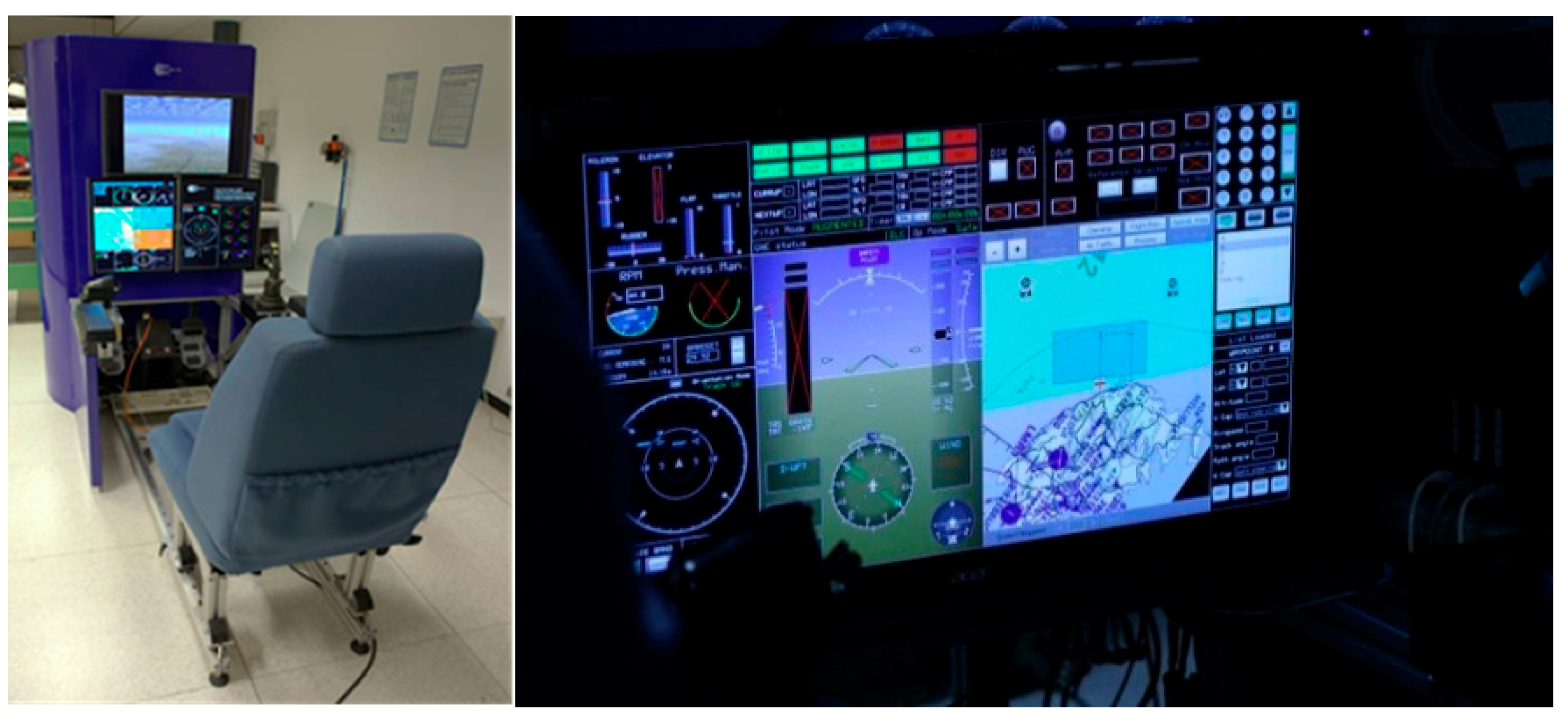
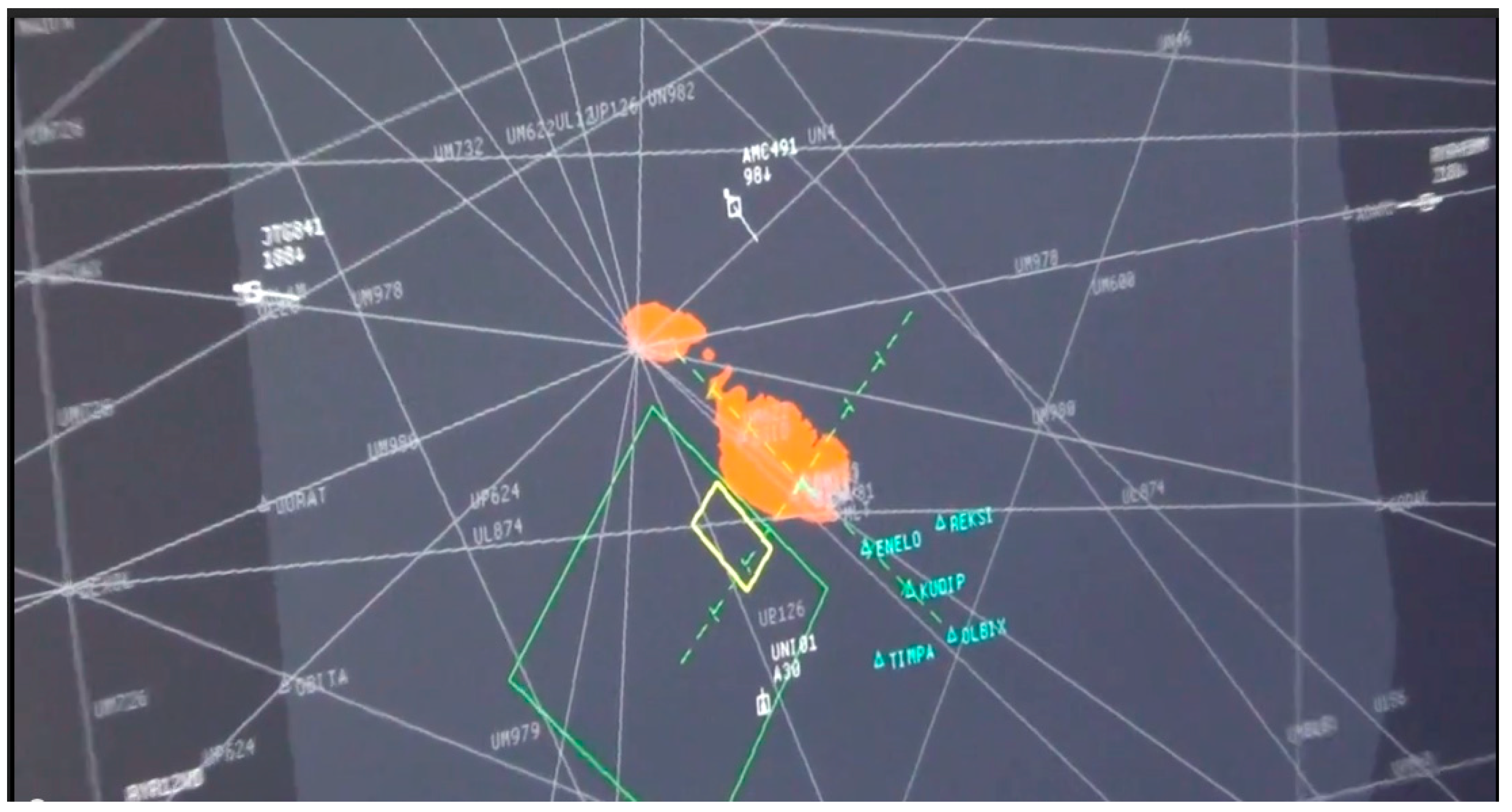
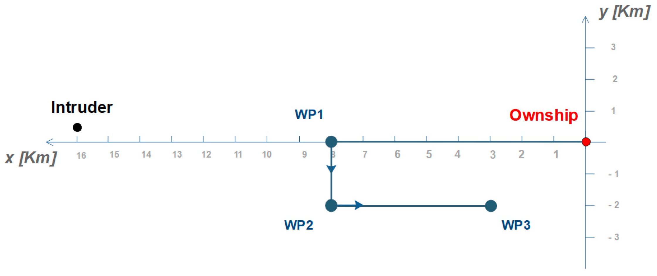
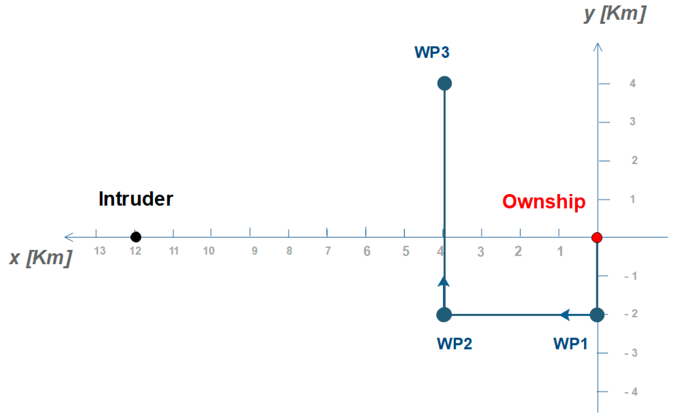
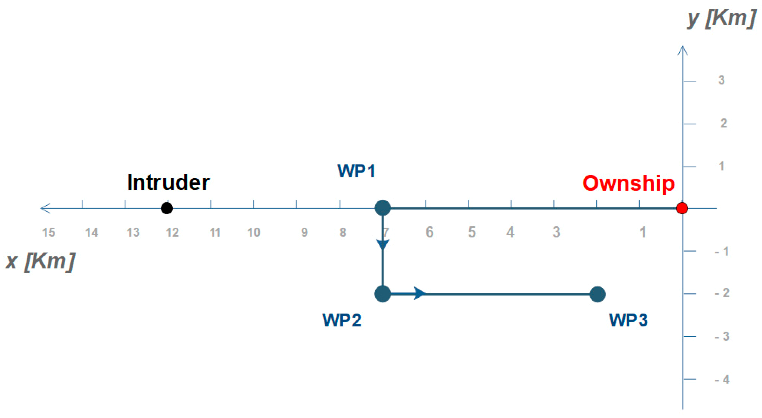
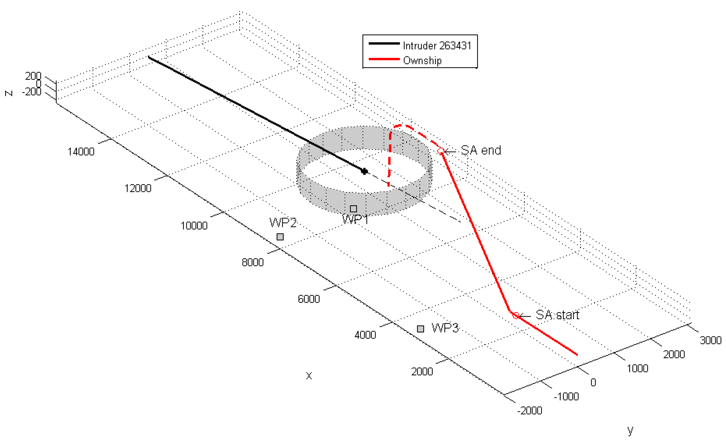
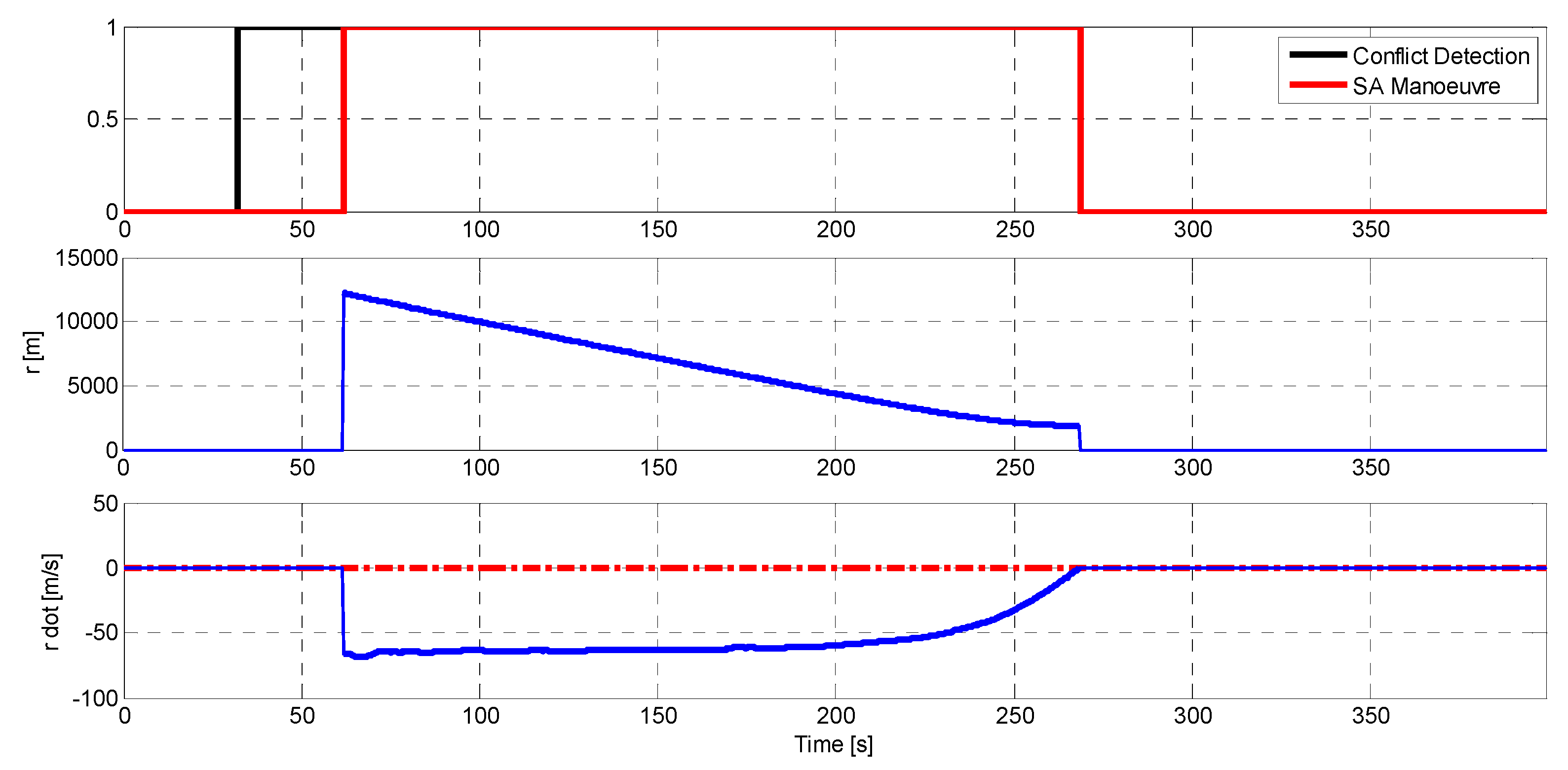
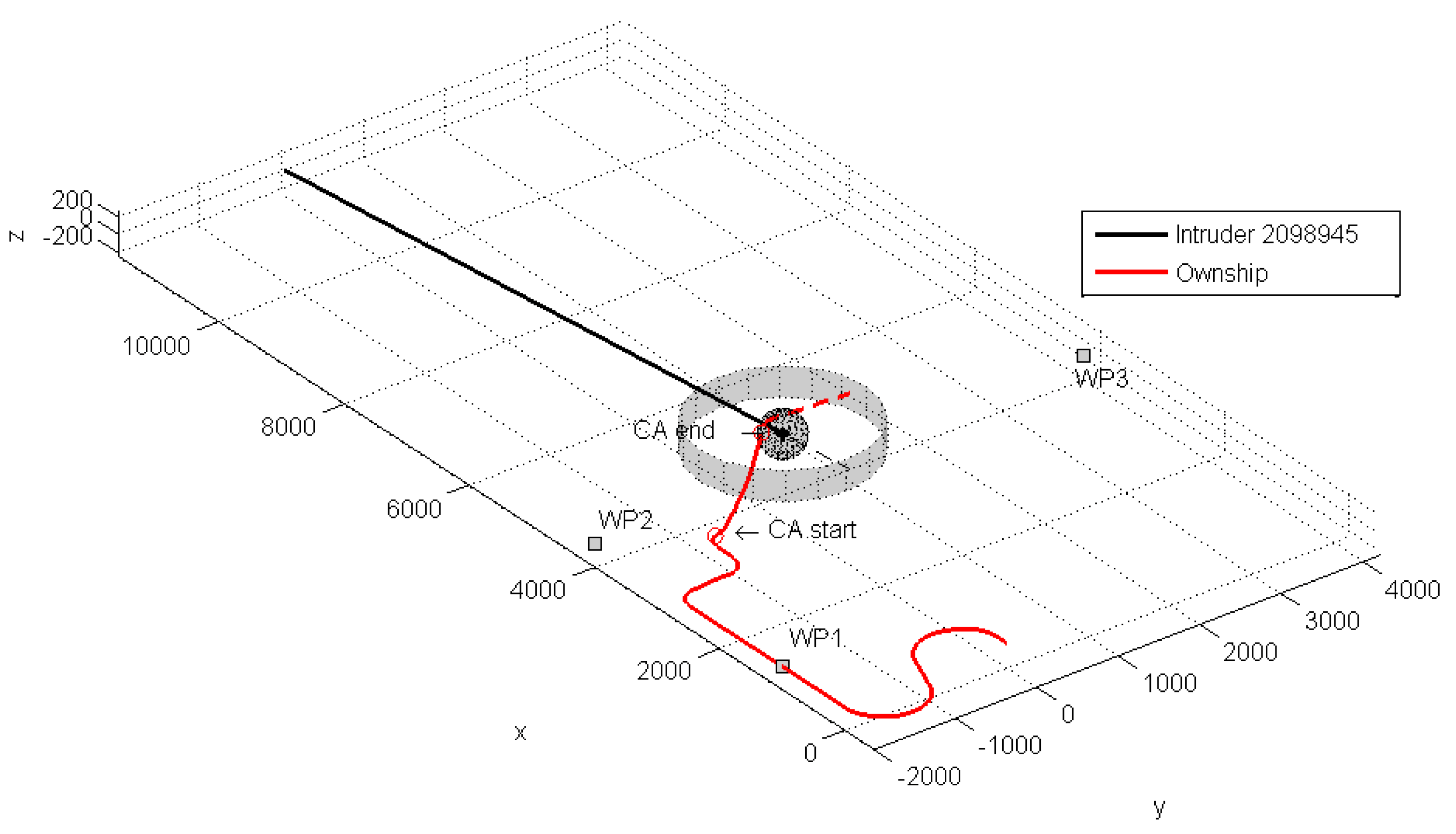
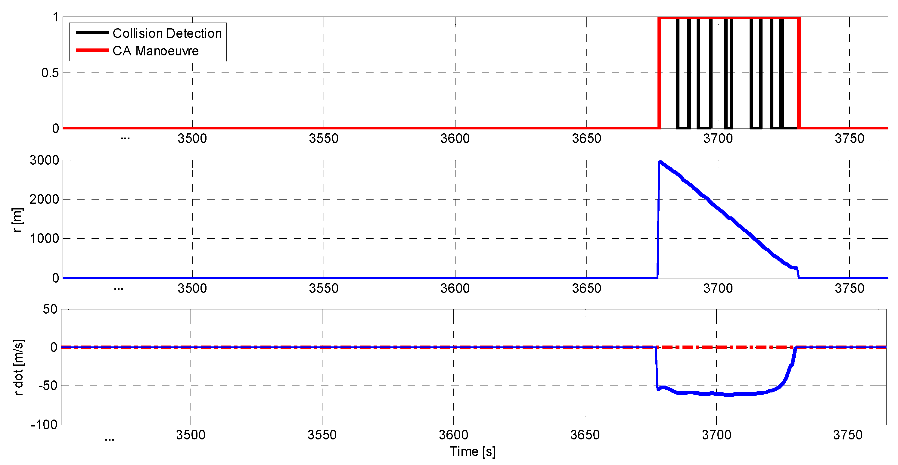
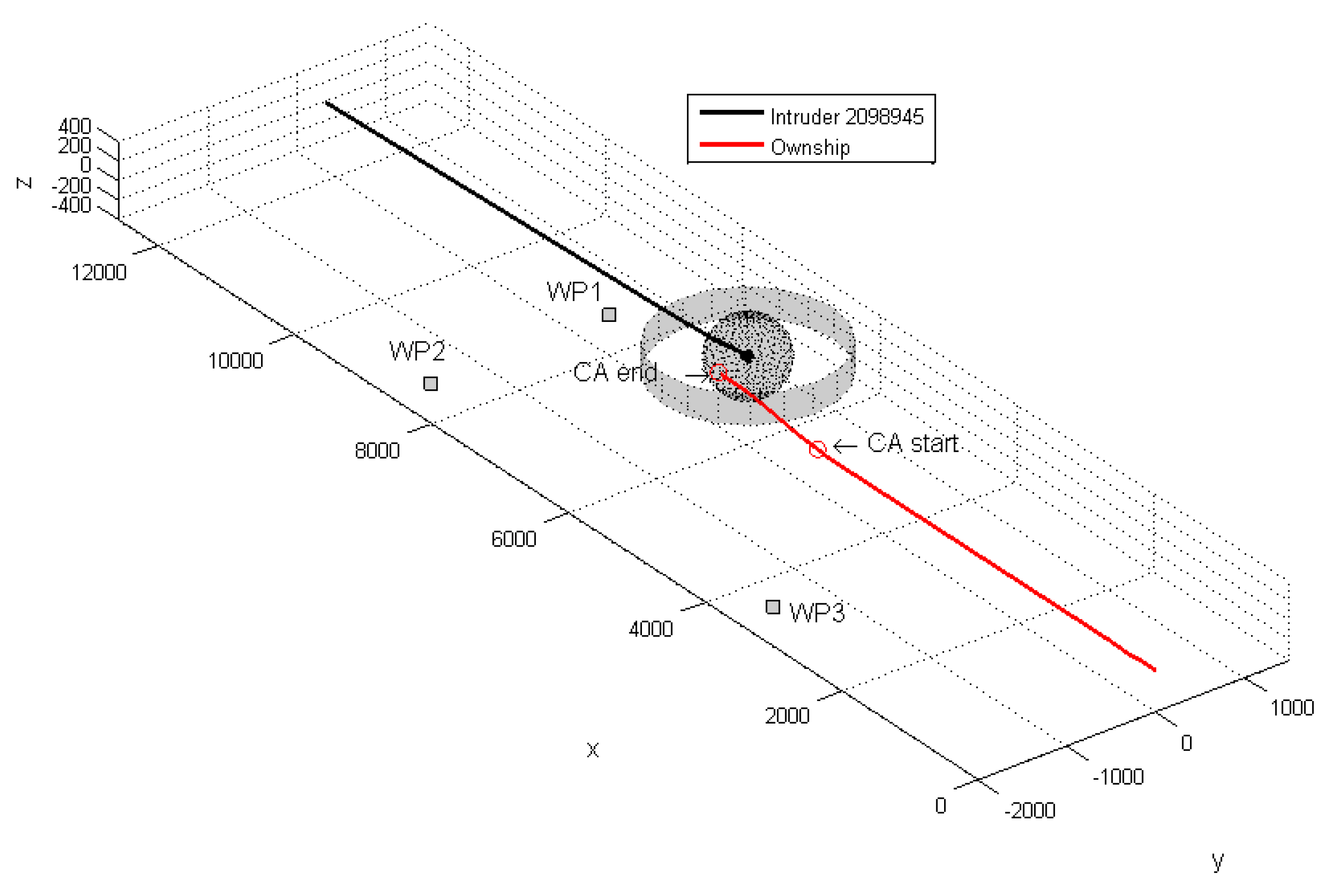
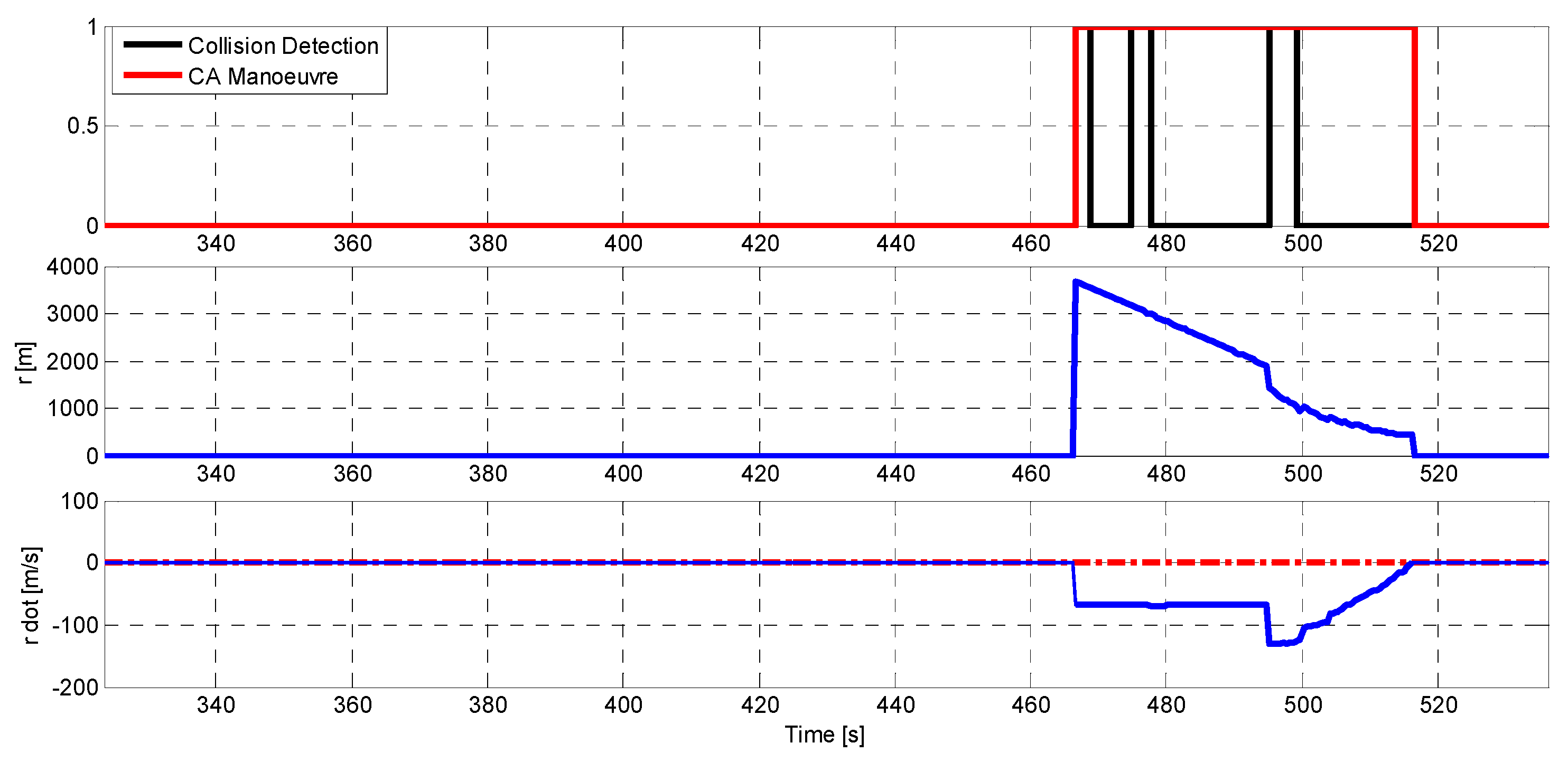
Table 1.
Summary of the test cases described in the paper.
| Test # | Addressed ASACAS Functionality | Encounter Geometry |
|---|---|---|
| 1 | Separation Assurance | Head-on |
| 2 | Collision Avoidance | Lateral |
| 3 | Collision Avoidance | Head-on |
Table 2.
Ownship RPAS and intruder starting position in local reference frame for test 1.
| x [m] | y [m] | z [m] | TAS [m/s] | Track wrt x [deg] | |
|---|---|---|---|---|---|
| Ownship | 0 | 0 | 0 | 35 | 0 |
| Intruder | 16,000 | 500 | 0 | 35 | 175 |
Table 3.
Ownship RPAS and intruder starting position in local reference frame for test 2.
| x [m] | y [m] | z [m] | TAS [m/s] | Track wrt x [deg] | |
|---|---|---|---|---|---|
| Ownship | 0 | 0 | 0 | 35 | 270 |
| Intruder | 12,000 | 0 | 0 | 35 | 175 |
Table 4.
Ownship RPAS and intruder starting position in local reference frame for test 3.
| x [m] | y [m] | z [m] | TAS [m/s] | Track wrt x [deg] | |
|---|---|---|---|---|---|
| Ownship | 0 | 0 | 0 | 35 | 0 |
| Intruder | 12,000 | 0 | 0 | 35 | 180 |
Publisher’s Note: MDPI stays neutral with regard to jurisdictional claims in published maps and institutional affiliations. |
© 2020 by the authors. Licensee MDPI, Basel, Switzerland. This article is an open access article distributed under the terms and conditions of the Creative Commons Attribution (CC BY) license (http://creativecommons.org/licenses/by/4.0/).
Share and Cite
MDPI and ACS Style
Di Vito, V.; Torrano, G. RPAS Automatic ADS-B Based Separation Assurance and Collision Avoidance System Real-Time Simulation Results. Drones 2020, 4, 73. https://0-doi-org.brum.beds.ac.uk/10.3390/drones4040073
AMA Style
Di Vito V, Torrano G. RPAS Automatic ADS-B Based Separation Assurance and Collision Avoidance System Real-Time Simulation Results. Drones. 2020; 4(4):73. https://0-doi-org.brum.beds.ac.uk/10.3390/drones4040073
Chicago/Turabian StyleDi Vito, Vittorio, and Giulia Torrano. 2020. "RPAS Automatic ADS-B Based Separation Assurance and Collision Avoidance System Real-Time Simulation Results" Drones 4, no. 4: 73. https://0-doi-org.brum.beds.ac.uk/10.3390/drones4040073