Aerial and Ground Robot Collaboration for Autonomous Mapping in Search and Rescue Missions


1
School of Electrical and Computer Engineering, Technical University of Crete, GR-73100 Chania, Greece
2
SenseLab Research, Technical University of Crete, GR-73100 Chania, Greece
*
Author to whom correspondence should be addressed.
Drones 2020, 4(4), 79; https://0-doi-org.brum.beds.ac.uk/10.3390/drones4040079
Submission received: 26 October 2020
/
Revised: 11 December 2020
/
Accepted: 14 December 2020
/
Published: 19 December 2020
Abstract
:Humanitarian Crisis scenarios typically require immediate rescue intervention. In many cases, the conditions at a scene may be prohibitive for human rescuers to provide instant aid, because of hazardous, unexpected, and human threatening situations. These scenarios are ideal for autonomous mobile robot systems to assist in searching and even rescuing individuals. In this study, we present a synchronous ground-aerial robot collaboration approach, under which an Unmanned Aerial Vehicle (UAV) and a humanoid robot solve a Search and Rescue scenario locally, without the aid of a commonly used Global Navigation Satellite System (GNSS). Specifically, the UAV uses a combination of Simultaneous Localization and Mapping and OctoMap approaches to extract a 2.5D occupancy grid map of the unknown area in relation to the humanoid robot. The humanoid robot receives a goal position in the created map and executes a path planning algorithm in order to estimate the FootStep navigation trajectory for reaching the goal. As the humanoid robot navigates, it localizes itself in the map while using an adaptive Monte-Carlo Localization algorithm by combining local odometry data with sensor observations from the UAV. Finally, the humanoid robot performs visual human body detection while using camera data through a Darknet pre-trained neural network. The proposed robot collaboration scheme has been tested under a proof of concept setting in an exterior GNSS-denied environment.
1. Introduction
Humanitarian Crisis scenarios occur frequently and they typically require immediate rescue intervention. In many cases, the scene conditions may be prohibitive for the human rescuers to provide instant aid, as they have to act within hazardous conditions, like collapsed buildings, air-poisoned, or radioactive environments. Many organizations and research teams are developing rescuing robots in order to assist "human" Search and Rescue (SAR) teams. These mobile robots can be equipped with a variety of sensors, actuators, and embedded processing units, depending on the scenario that they operate on. Because of their special-purpose construction, they can achieve sufficient maneuverability in the terrain that they were designed for and may perform mapping, searching, and reconnaissance procedures by processing the captured data from their sensors. These robots can either be autonomous or remotely-operated. In cases, such as collapsed buildings or densely obstructed areas, the robot remote operation may be limited or inapplicable, so the robot needs to be able to determine its own localization and find its way in the unknown environment. Moreover, even under the assumption that the area map is known, it cannot be taken for granted that the map remains precise, especially after disaster scenarios. Hence, in many cases, the robots need to be able to reconstruct the map of their surrounding environment and also localize themselves in it, without human supervision. Furthermore, in multi-robot scenarios, it is also critical for the robots to recognize and localize other robots in the field. Additionally, assuming that the robots are aware of the generated map and their local position, path planning approaches can extract the most appropriate path towards a given target location. Consequently, multiple robots need to cooperate with each other, in order to accomplish their missions faster and more efficiently.
Multi-robot approaches are often proposed in several non-trivial situations, as they have several advantages when compared to single-robot systems, especially in Search and Rescue scenarios. Through their cooperation, they can optimally manage requested tasks according to the current problem, they can combine collected information, they can split a common problem, and, consequently, accomplish mission tasks faster.
Autonomous mobile navigation has been an area of increasing research interest. Most approaches [1,2,3] focus on systems for outdoor search operations, which require the support of GNSS satellites to acquire their location, achieving a localization error of several meters. In contrast to satellite-based systems, which remain the standard in outdoor navigation scenarios, in indoor navigation scenarios, GNSS localization is not supported. Indoor localization is based on dedicated infrastructure and customized mobile robot units, depending on the scenario, while using wireless and non-radio technologies.
In the first category, the robot location estimation is performed by extracting information from the existing wireless infrastructure. Specifically, there are approaches that use signal strength measurements from WiFi access points [4,5] or from Bluetooth low-energy beacons [6], in an organized network and, thus, with the combination of robot’s odometry data, they can estimate its location. In addition, there are studies on cheaper indoor localization solutions, like the use of Radio Frequency IDentification (RFID) technology [7,8], in which localization is achieved through the Received Signal Strength (RSS) in a known arranged grid of passive tags, set up in the area, using a RFID reader that was attached on the robot frame. However, these implementations require some preparatory work on setting up the wireless infrastructure and preparing the area accordingly, in order to proceed with the mapping process. Therefore, these approaches are time-consuming and require prior installation, thus they are inapplicable to emergency situations.
In the second category, the mobile robot is equipped with necessary sensors and performs the localization itself, without any interfering external supporting infrastructure. Recently, Xing et al. [9] implemented a marker-based multi-sensor indoor navigation algorithm, ideal for Micro Aerial Vehicles (MAVs), which uses the fusion of the inertial sensor raw data and ultrasonic sensor measurements with the visual spatial information of the proposed markers, which are placed randomly on the ground. Additionally, an indoor localization approach [10] shows the capability of a mobile robot to be able to navigate indoors, by using the information from its odometry, fused with the orientation data from an attached electronic compass. There are also hybrid approaches that combine, e.g., WiFi network RSS measurements with inertia measurement unit raw data [4] and odometry data [11].
Simultaneous Localization And Mapping (SLAM) algorithms are capable of simultaneously building a map of the surrounding environment (indoor or outdoor) and localizing the robot in it. In RoboCup Rescue competition, Visual SLAM implementations have demonstrated promising results [12], but they are limited due to camera induced distortions and imaging conditions, which require high computational resources. The Gmapping approach [13], which is based on Rao-Blackwellized particle filtering, is a widely-known, open-source SLAM algorithm. This method depends on sufficient and accurate odometry data and it is affected by roll and pitch motions (only planar environments are considered), which makes it inapplicable to UAVs. On the other hand, several approaches for quadcopters in the literature [14] solve the SLAM problem with the use of a LiDAR system, but they do not provide a full 6-DoF (Degrees of Freedom) pose estimate. Team Hector [15] developed an open-source flexible SLAM system, which was specifically designed for Urban Search And Rescue (USAR) scenarios in RoboCup Rescue. This system relies on fast LiDAR data scan-matching at full update rate and inertial data, providing 6-DoF pose information regarding the moving robot. Since then, Hector SLAM has been used as a standard SLAM implementation in a plethora of robotic exploration applications.
The area of cooperative robotics is a research area that has made significant progress in the past few years. Specifically, in SAR scenarios, multi-robot systems could cover an area more efficiently than a single-robot system. Many studies [16,17,18] have been implemented for multi-robot cooperation in SAR scenarios, but they only consider ground mobile robots. In addition, Cai et al. [19] use a MAV integrated in a ground-robot team to perform localization and mapping algorithms through a low-cost range finder sensor, transmitting all of the sensor information to a portable PC for processing. Furthermore, there are approaches that use dedicated middleware for SAR scenarios, such as CINeMA [20], in order to ensure network connectivity and cooperative robot localization.
In this study, a ground-aerial robot collaboration approach is proposed, in which a UAV and a humanoid robot cooperate to solve a real-world SAR scenario. In particular, each robot is assigned with specific roles, in order to cooperate on the task of locating humans in need. By assuming that the ground robot cannot take any spatial measurements, we approach its localization problem through the aerial robot’s view. The ground robot plans its own paths to given targets in the map that was provided by the UAV, and it is responsible for locating victims on the ground, which may not be visible from the UAV. The main objective of this study is to implement a full end-to-end robot collaboration scenario under the restrictions of the actual robots at hand. While several studies are approached on a theoretical basis, this study is one of the few that uses common aerial and ground robots with specific implementation capabilities and limitations. Thus, due to the complexity and variability of the steps required to fulfill the SAR scenario, the proposed robot collaboration is implemented as a proof-of-concept integration study, through a test execution in order to demonstrate its potential applicability. The scientific contribution of the current study resides both in its applicability and implementation. In terms of applicability, since this is one of the few implemented multi-robot studies, we address the wide range of problem-solving potential through the collaboration of ground and aerial robots under varying limitations on environments, sensors, and specifications. Furthermore, the integrated implementation solution is not demonstrated in virtual environments, as most of the related studies, which showcase real-life experiments, use quite demanding and state-of-the-art algorithms and integrated sensor types.
In Section 2, the equipment and sensors that are used to support the proposed collaboration scheme are thoroughly presented. Section 3 describes, in detail, the implementation steps of the proposed approach, starting with the aerial robot’s mapping procedures and concluding with the localization of human victims in the unknown environment by the ground robot. Section 4 provides the corresponding proof-of-concept testing, as we present the entire system with real-world experiments in an outdoor environment. Finally, Section 5 provides a short discussion on the results and future perspectives of this study.
2. Robots and Sensors
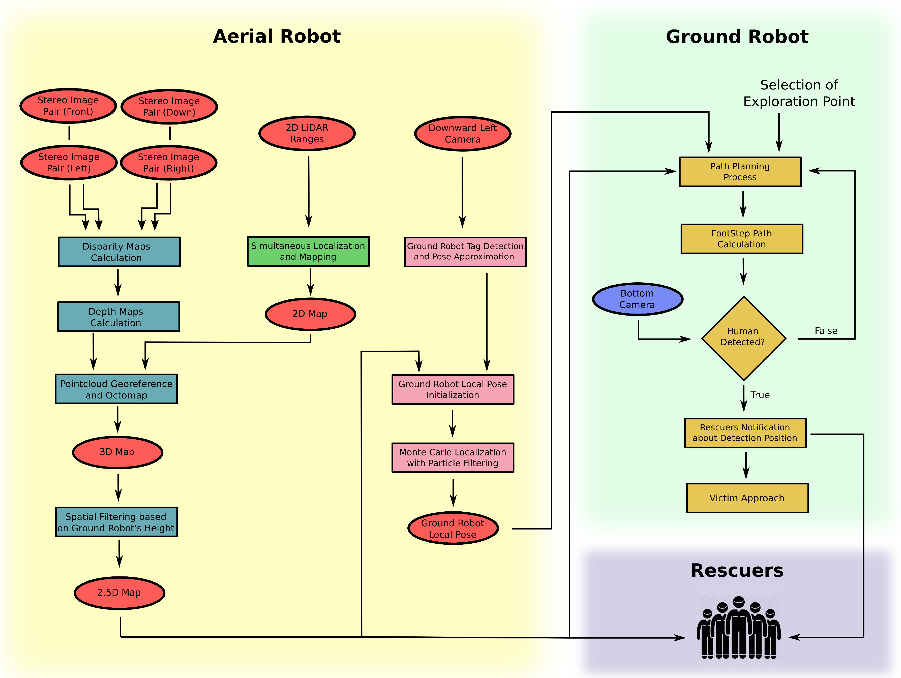
In this section, the overall architecture of the collaborative approach, as shown in Figure 1, is initially described, while robots and sensors are thoroughly presented in the rest of the section. The main assumptions of the present study, beyond the restrictions that are induced by the equipment themselves, include: (a) both robots have no prior localization information or GNSS navigation sensor, (b) the aerial robot cannot detect the humans in need due to possible occlusions, and (c) the ground robot has no mapping sensors or a corresponding algorithm to aid in its navigation.
As a high-level introduction to the presented methodology, the UAV performs a combination of two-dimensional (2D) and three-dimensional (3D) mapping in order to extract a 2.5D map, which is specifically made for the humanoid robot’s navigation. The UAV extracts depth information through a multi-stereo camera system and then uses an octree mapping method in order to construct a 3D world representation. At the same time, it constructs a 2D map that is based on the laser ranging data (LiDAR), while a SLAM approach is performed to estimate UAV’s poses in the generated map. Consequently, a world representation is obtained and transferred to the humanoid robot, in order to proceed with the mission. At the same time, the UAV searches for the location of the humanoid robot on the ground. Once the ground robot is identified, the UAV can calculate the ground robot’s pose within the map frame by detecting the Augmented Reality (AR) marker mounted on its head and by referencing the ground robot position with respect to itself. In addition, the UAV is able to transform LiDAR spatial data to the most recently acquired ground robot position. Given this transformation, the ground robot can perceive the world through the UAV vision system, while its localization method is performed by an adaptive Monte Carlo particle filtering method. Finally, the humanoid robot uses a Path planner and a FootStep planner in order to obtain an obstacle-free path to any desired target location in the map. While exploring the area, a neural network, which is based on Darknet framework, is used for human detection. Once a human is detected, it is approached for better view and the human rescue team is notified. This procedure is continuously repeated.
This collaborative approach is designed to make the best use of both robot platforms, with respect to their computational capabilities and onboard sensory. The entire methodology has been implemented within the Robot Operating System (ROS) framework [21], and it can be applied to any ground-aerial multi-robot system, as long as proper adjustments are established.
2.1. Robots
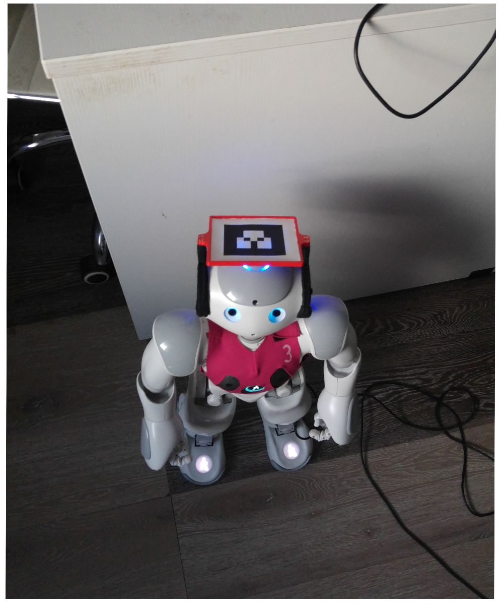
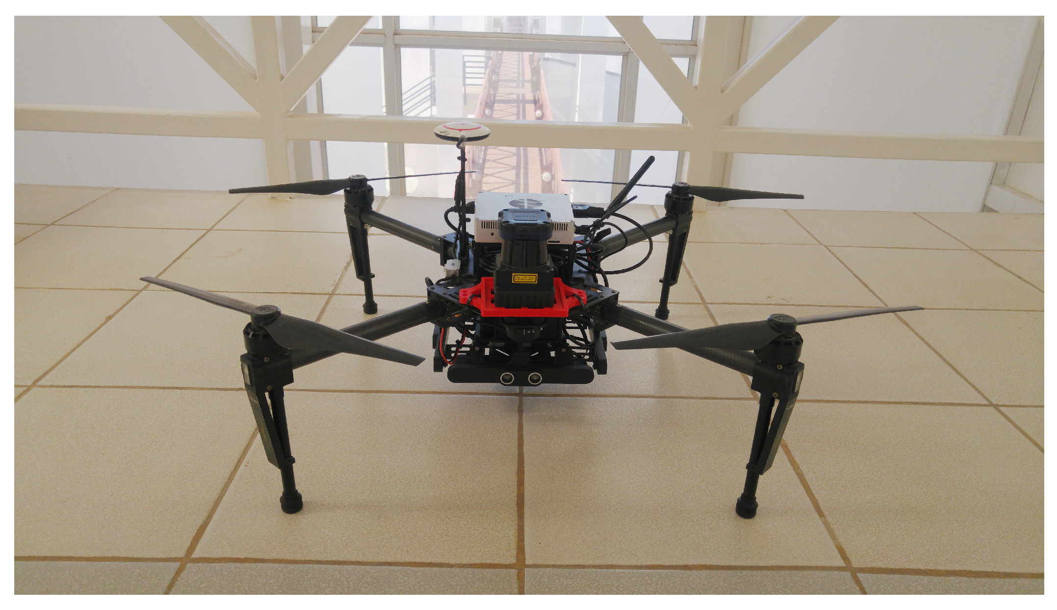
For the purpose of demonstrating the proposed methodology, two specific robotic platforms, already available in our laboratories, were selected for the implementation. Specifically, for the ground robot, we selected the Aldebaran Nao V5 humanoid robot (Aldebaran Robotics, Paris, France), shown in Figure 2, and for the aerial robot the DJI Matrice 100 (M100, SZ DJI Technology Co., Ltd, Shenzhen, Guangdong, China), shown in Figure 3. Thus, in this subsection, the selected robot specifications and their networking capabilities are described.
The Aldebaran Nao [22] is a programmable, medium-sized humanoid robot that is designed and manufactured by Aldebaran Robotics (SoftBank Robotics). On the technical side, Nao V5 has a built-in Intel ATOM Z530 processor at 1.6 GHz clock and 1 GB of RAM, which makes it capable of completing simple tasks and also 2 GB of flash memory with an embedded GNU/Linux distribution. It is powered by a six-cell Li-ion battery and it has a IEEE 802.11g network card and a RJ-45 Ethernet connection port for wireless or wired communication. In addition, Nao is equipped with a variety of actuator and sensor units. Specifically, it has 25 motors that provide 25 degrees of freedom on its body parts. Each joint comes with a magnetic rotary encoder, which provides pose information about the specific joint in precision of 12 bits or 0.1 of angle resolution. On the sensors side, there are tactile sensors, touch sensors, ultrasonic sensors, force sensitive resistors, cameras, and an inertial unit. On the software side, Nao has an embedded computer system, which runs a Gentoo-alike GNU/Linux distribution. The Nao robot is controlled by the provided middleware, called NAOqi. The NAOqi framework supports cross-language execution and also provides introspection, which means that the framework knows which functions are available in the different modules and where. Additionally, NAOqi allows for homogeneous communication between different modules (motion, audio, video) and programming capabilities. NAOqi supports direct software development in C++ and Python and it has a fully-developed ROS driver, which was developed by Freiburg’s Humanoid Robots Lab and Armin Hornung [23]. Through this driver, all Aldebaran’s NAOqi API parts are wrapped and made available for use in the ROS environment.
The Matrice 100 [24] is a quadcopter, designed and manufactured by DJI, mainly for developers. It comes with its own SDK and includes an onboard processing unit for programming, called "Manifold". Manifold packs a Quad-core ARM processor, along with a low-power NVIDIA Kepler-based GeForce graphics processor, so it is capable of completing any simple or demanding task. It also has a built-in special version of Ubuntu GNU/Linux operating system, which is developed to have fully DJI SDK accessibility and control, and it has real-time access to flight and raw sensor data. Equipped with Ethernet, Mini-PCIe, UART, SPI, I2C, and USB ports, the Manifold allows connections to a wide array of sensors, depending on the scenario being followed. Similarly, the DJI SDK features a dedicated ROS package module [25] that is available from the open-source ROS stacks.
2.2. Robots’ Network
An appropriate and adequate connection is required for their communication in order to achieve the aerial-ground robot collaboration. A wireless connection is ideal for the inter-robot communication and monitoring due to the variety of environmental conditions and rescuing scene’s morphology (i.e., urban environments, outdoor situations, and more).
Specifically, we propose a 2.4 GHz WiFi network setup, which is sufficient for most of the tested cases, as it includes a mapping coverage of 15 m–20 m and it can be deployed easily and quickly. The 2.4 GHz, as compared to the 5 GHz frequency band, was selected to achieve wider range coverage, as the latter frequency signals may be absorbed or obstructed in urban or high-vegetation environmental conditions. Each mobile robot is assigned a known static IP address, which was obtained from the router device during connection. The ground station (a laptop in our case) is also connected to the same network, either through wireless or wired connection, and it is used for monitoring and testing.
Because the ROS core uses the system clock for applying timestamps on streaming data, there may be time differences when both systems initiate. For this reason, whenever the systems are powered up, both robot system clocks are reset according to a common NTP server clock. In this way, all of the generated ROS messages from either robot will be synchronized and processed correctly with respect to time. When Internet connection is unavailable, various Unix packages, such as chrony, can be used to mitigate robotic systems heterochronism.
2.3. Onboard Sensors
The robots are equipped with several sensors, which are used to extract information regarding the environment around them in order to accomplish the SAR objectives. In this section, the used onboard sensory modules will be described along with the methods of obtaining spatial and other data.
2.3.1. Laser Scanner Module
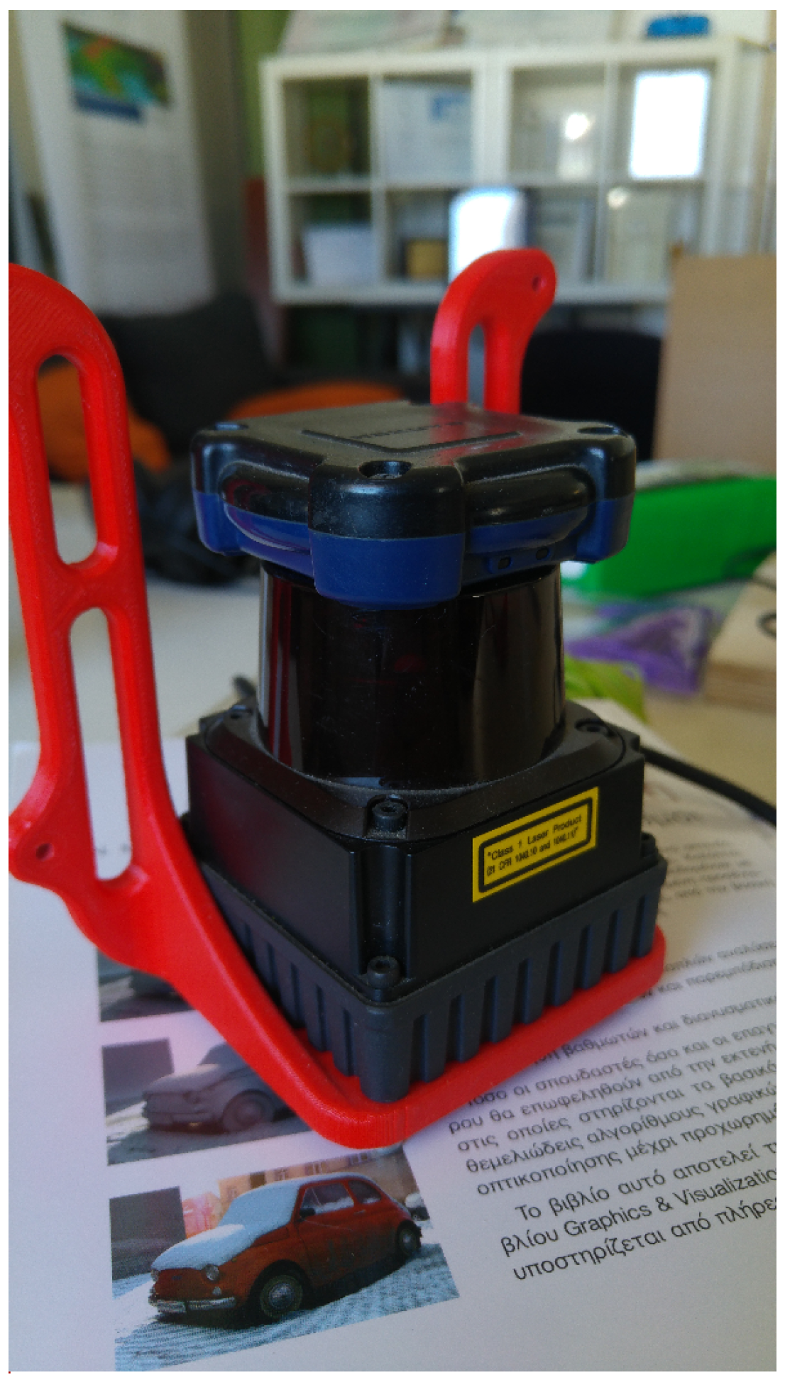
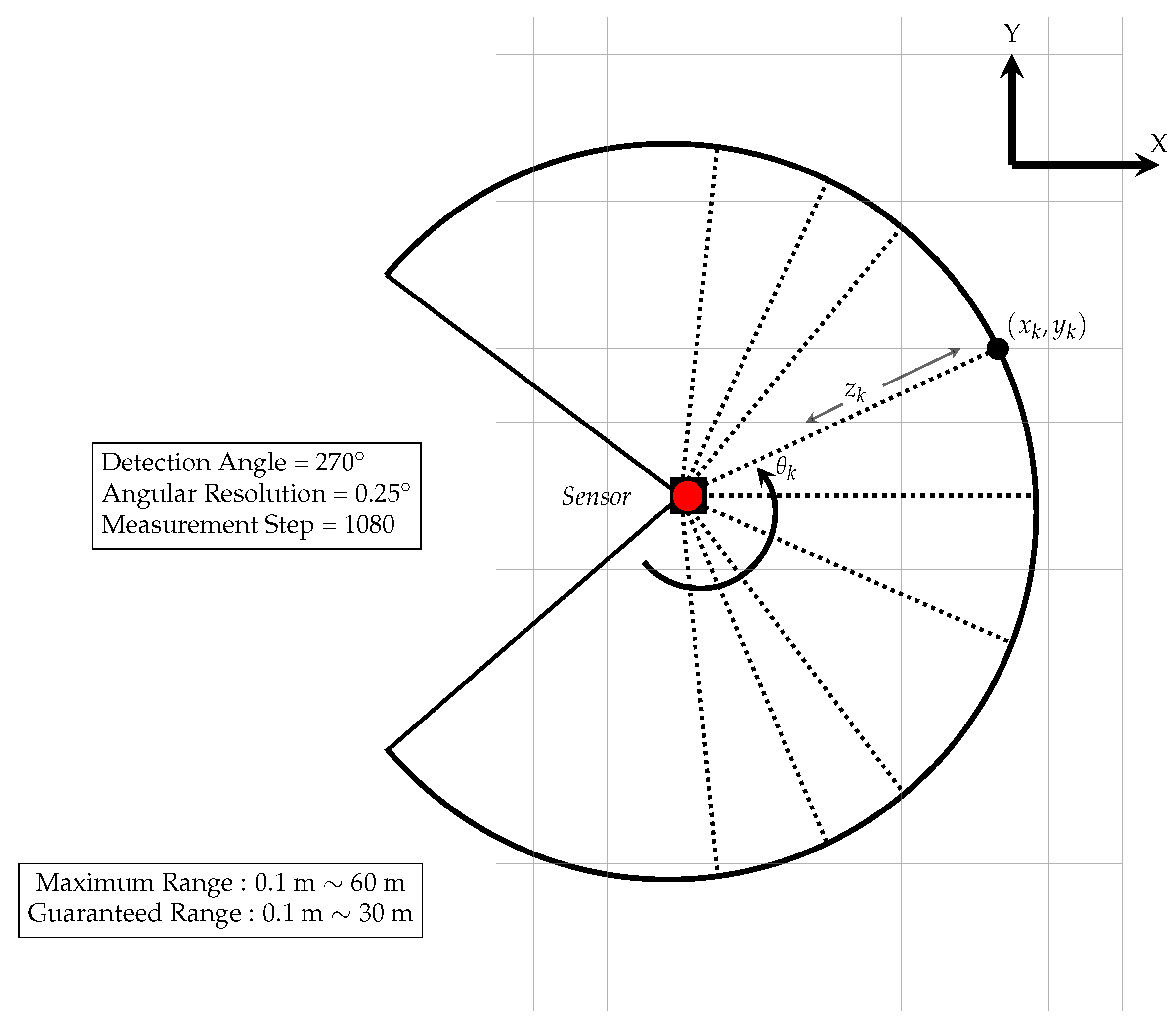
The Light Detection and Ranging (LiDAR) system is a laser-scanning device that can provide precise distance information within the scanning area. These sensors are broadly used on many mobile platforms (autonomous cars, satellites, airplanes, and more), in order to determine absolute position and orientation, with respect to the surrounding environment. In our scenario, we attach a 2D LiDAR sensor, specifically the Hokuyo UTM-30LX-EW, (Hokuyo Automatic Co., Ltd., Osaka, Japan) (as shown in Figure 4), on the UAV system, which is used for its localization and mapping procedures.
Particularly, this sensor provides 1080 range measurements in a full scan ( scanning angle with of angular resolution, as seen in Figure 5). The scanning plane of this LiDAR is parallel to the plane and it provides raw distance measurements (, ) in a polar coordinate system. These measurements can be expressed in the Cartesian coordinate system, as,
where the kth-measured end point at kth-scanned angle at step time t. In Equation (1), all of measurements have zero z-axis values, because they lie on the same plane.
When assuming that is the robot pose at time t, is the relative location of the LiDAR sensor in the robot’s local frame, and is the angular orientation of the sensor beam relative to the robot heading direction, the LiDAR measurements can be expressed through the following trigonometric transformation in global coordinates:
where is the rotation matrix that aligns the LiDAR sensor with the the robot’s heading direction. Consequently, all of the captured ranging data are referenced according to the LiDAR coordinate system and can be described in any other onboard UAV frame using the corresponding transformation relation.
2.3.2. DJI Guidance Module
For the 3D mapping procedure of the UAV system, the DJI Guidance system is utilized. This system integrates five similar sensor units, equipped with a pair of visual cameras (stereo camera system), which provide grayscale images and an ultrasonic ranging sensor. These sensor units are positioned towards each main navigation direction, except one that faces upwards. Hence, by mounting this module underneath the UAV body, online surrounding area mapping can be performed, ideally by processing the stereo image captures from each integrated sensor unit.
2.4. Coordinate Systems and Transformations
Robot collaboration requires the representation of the positions and orientations of robots, including their sub-system parts, in the same coordinate system in order to be able to georeference each other. The coordinate systems described herein involve local Cartesian three-dimensional coordinate systems, where x, y, and z coordinates are arbitrarily defined with a given origin and direction. It is assumed that each interacting robot part is described by its own coordinate system and origin, namely frame, which is localized by a position and a rotation vector in reference to a global frame.
Many complex robot systems consist of parts that move with respect to a base frame, i.e., the hands of a humanoid robot with respect to its torso frame. This means that the transformation matrix between two specific moving parts (frames) varies over time as the parts move. Thus, it is necessary to store the corresponding timestamp information each time that there is a spatial update between the existing frames. Similarly, each captured spatial measurement must be also described with respect to the coordinate system of the corresponding sensor and it should have its own capture timestamp information. The frames’ transformation data are manipulated through the integrated ROS library, namely the tf transformation library [26].
Essential steps had to be made to extract their stereo specifications information in order to obtain 3D spatial information by using the onboard stereo cameras. Because every stereo camera integrates two monocular cameras, calibration procedures had to be made in order to extract their specific camera information matrices, namely the camera matrix K and distortion coefficients matrix D:
where and are the focal length values of each image plane axis, s is the skew parameter, and , are the principal point coordinates. Additionally, the distortion coefficients matrix is formed as:
where the ’s and the ’s are the radial and tangential distortion coefficients, respectively. Given these matrices, every 3D world point can be projected on the camera’s image plane and, thus, it is easy to obtain its image coordinates.
3. Methodology
In the following subsections, the methods, algorithms, and implementation specifics of the robot collaboration scheme are sequentially presented, building up from the mapping stage of the UAV to the collaboration and path planning of the ground robot towards its final target recognition. Section 3.1, Section 3.2, Section 3.3, Section 3.4, Section 3.5 refer to the UAV, Section 3.6 and Section 3.7 to the UAV and ground robot collaboration, while Section 3.8 and Section 3.9 mainly describe implementations on the ground robot, while using already transferred information and data from the UAV. Each subsection begins with an objective statement to aid the in reader following the overall methodology.
3.1. Stereo Matching and Disparity Map Generation
Objective: Estimate the disparity map of the UAV’s field of view through stereo matching (Figure 1, beginning of first column).
In order to be able to operate in the rescuing area, the UAV has to construct a “belief” about the environment (an estimate) through a sufficient 3D map representation and share it with the ground robot. This 3D map is reconstructed through its onboard stereo camera sensors. A fundamental problem of any stereo imaging process is the stereo correspondence/matching, which is defined as the procedure of detecting similar features between the two cameras’ image planes, and based on the estimation of the disparity map. The disparity map combined with the rectified cameras’ image planes provides the depth map of the viewed scene.
Stereo matching methods can be distinguished in two categories, the local and the global. Local methods are based on intrinsic parameters of the selected regions that they are trying to match and limit their searches to small image regions. In particular, local methods perform the matching process by either discrete feature matching or correlating small image patches that are described by a pattern. Feature-based local matching algorithms, in spite of their accuracy and rapidness, require high-computational resources to be executed in real time. In contrast, area correlation methods appear to be computationally efficient, since they do not require the extraction of global features. The stereo matching approach of K. Konolige [27], namely the Stereo Block Matching (BM) algorithm, uses transformations on pixel intensities to compare different areas and perform area correlation.
In our case, for enhancing stereo matching, while keeping the computational demands at similar complexity levels, we use a global block matching method, which is known as Semi-Global Matching (SGM) [28]. The SGM method performs pixel-level region matching, as it approximates a global cost function by path-wise optimizations from all directions through the image. Given that SGM is a semi-global method, the disparity map computation is done by selecting the disparity values for each pixel individually that corresponds to the minimum cost (local optimum), while enforcing the smoothness constraints in order to penalize the changes of neighboring disparities.
3.2. Weighted Least-Squares Filter and Fast-Global Smoother Algorithm
Objective: provide an optimized sharp disparity map of the previous step (Figure 1, first column).
In 2008, Z. Farbman et al. [29] presented a multi-scale edge-preserving decomposition method for images, in order to extract and retain multi-scale detail characteristics. Particularly, this edge-preserving operator is based on the Weighted Least-Squares (WLS) framework and it is ideal for progressive imagery coarsening, as well as detailed extraction in various spatial scales.
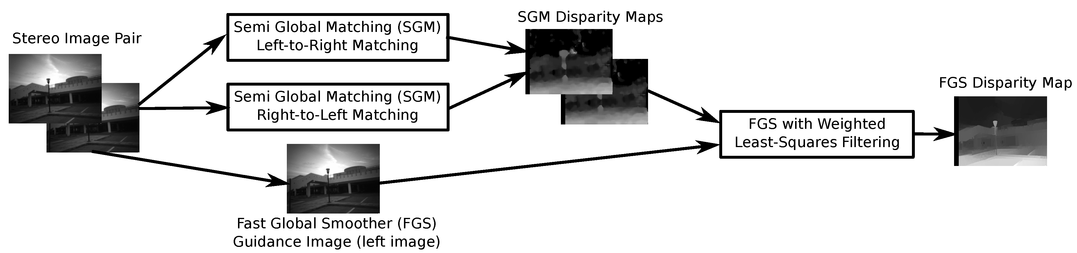
In 2014, D. Min et al. [30] used the WLS decomposition operator in order to implement an inhomogeneous global edge-preserving smoothing method, namely the Fast Global Smoother (FGS). This technique enabled faster global objective function approximation. As a global smoother algorithm, it has been tested in a variety of computer vision applications, including depth up-sampling tasks. For this reason, the FGS algorithm can be used to up-sample low-resolution depth maps, through a sparse data interpolation method, under which it defines the initial captured image as the guidance image and computes depth maps with enhanced spatial resolution.
Specifically, when combined with the SGM method, the FGS filter makes use of the left-right consistency-based confidence to refine the results in half-occlusions and uniform disparity areas. In our approach, we defined left gray-scaled stereo-pair view as the FGS’s Guidance image and set it as the main matcher. Subsequently, the WLS-filter initialized the right matcher, with respect to the main (left) matcher, in order to be able to compute the right-view disparity map. As the disparity computations are performed through the SGM method, from each stereo view individually, we apply the WLS-filter by giving the main view and the two calculated disparities (left-to-right and right-to-left) as input. The output disparity image is the up-scaled WLS-filtered disparity image, which has selectively preserved the sharp edges by fading the small in magnitude features and enhancing the low-textured areas. Figure 6 illustrates the entire procedure.
3.3. Depth Image Calculation and Point Cloud Generation
Objective: Generate a point cloud from the depth map.
By extracting the disparity map of the current scene along with the calibrated stereo camera system, the depth information can be directly calculated. Through this way, each pixel coordinate contains depth information with respect to the stereo camera’s coordinate system and, thus, to further process it, we manipulate it as a point cloud structure.
Specifically, the Point Cloud Library (PCL) [31] is an open source C++ library, which is specially designed for 3D point cloud processing. Because of its integration within the ROS architecture, it was the ideal library to manipulate the stereo matching computed 3D depth maps. Specifically, we express the depth maps in point clouds message forms by using shared pointers, in order to manage the memory consumption due to their large number and achieve faster computations.
3.4. OctoMap 3D Mapping
Objective: indexing the 3D map for optimized data manipulation (Figure 1, end of first column).
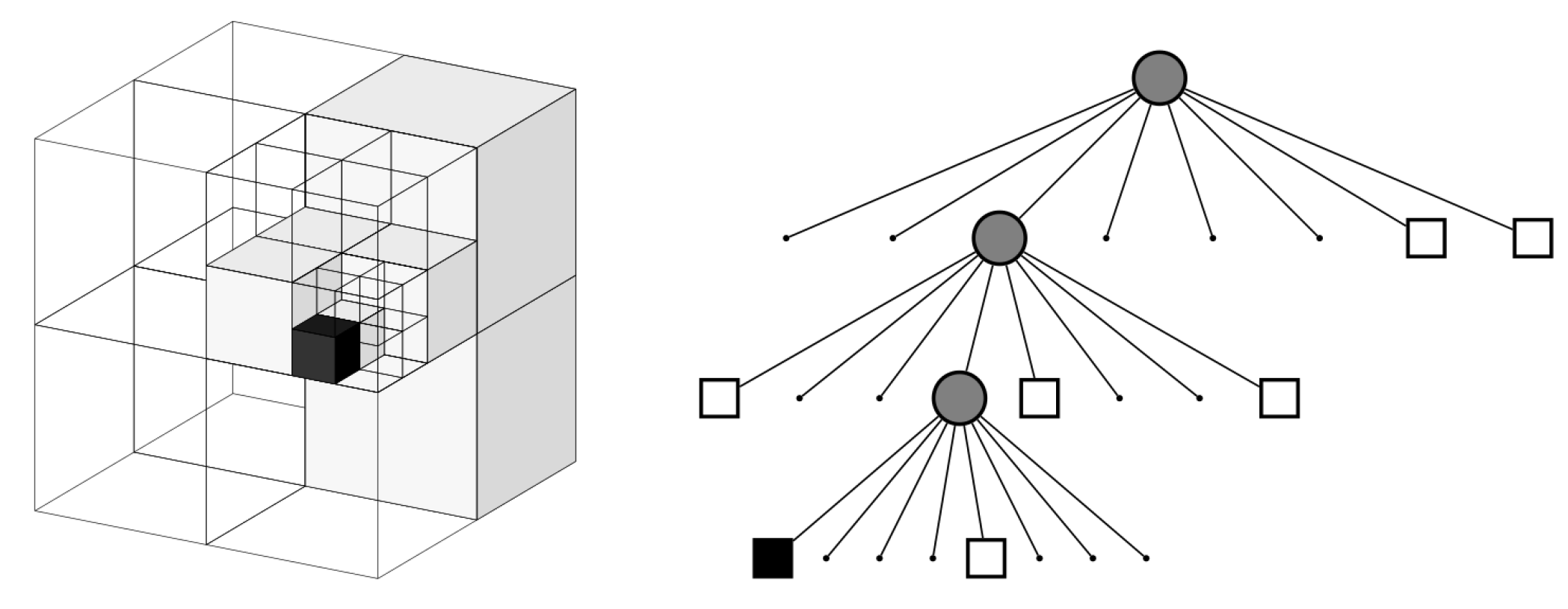
Because spatial information is obtained in metric units from the UAV’s surrounding 3D world, there is a need for applying a 3D mapping algorithm in order to construct a 3D map and estimate the optimal navigation path to solve the SAR scenario. Nonetheless, the point cloud can be large and, hence, memory demanding, especially for an on-board solution. Thus, the OctoMap framework [32] is an ideal choice for the 3D map indexing, as it can manipulate point cloud data and use a probabilistic approach to perform 3D mapping optimizing runtime and memory usage. Basically, it performs probabilistic occupancy updates for every 3D point measurement, as it estimates the occupied and unoccupied space through ray casting along the line from the sensor origin to the end point of a 3D measurement. The occupied, as well the unoccupied, space is spatially expressed with the octree data structure, as shown in Figure 7. Each node in an octree represents the space that is contained in a cubic volume, namely the voxel.
3.5. Hector SLAM and Fusion with OctoMap
Objective: localize UAV using SLAM on LiDAR data, correlating them with the 3D map (Figure 1, second column).
Because the OctoMap framework does not contain an integrated localization approach, it needs georeferenced UAV poses in the map frame, in order to correlate and stitch the captured point cloud data. Hence, we use a robust SLAM approach, based on the onboard LiDAR sensor scans, to approximate UAV’s corresponding poses in the map coordinate system and also generate the 2D map with respect to the UAV’s altitude level. Given the resulting 3D OctoMap representation and the 2D SLAM generated map, spatial data correlation and fusion are applied in order to produce a 2.5D map of the surrounding environment representation, at selected altitude levels, relative to our ground robot’s height.
The abilities of real-time self-localization and map generation of a mobile robot in an unknown area are crucial to be able to operate in real-world unstructured environments. Additionally, in SAR scenarios, time is an important factor to consider, as individuals could be in danger and need immediate assistance. Specifically, the Hector SLAM system [15] is utilized, which provides full 6-DoF robot pose estimation by also solving the Online SLAM problem reliably. The Hector system combines two subsystems, a 2D SLAM system that is based on the integration of laser scans in a planar map and an integrated 3D navigation system based on the integrated inertial measurement unit.
During the navigation, the captured distance ranges are expressed in the LiDAR’s frame. Given that, these measurements are spatially transformed through the UAV’s pose estimations and the spatial information from the transformation tree, into the UAV’s stabilized base frame coordinate system, in order to be expressed relative to the body frame. The Hector SLAM uses an occupancy grid map to retain the belief of the unknown environment map. Sub-grid cell approximation cannot be performed due to the occupancy grid map’s discrete form, as there is a limit to the map resolution parameter. For this reason, for any occupancy value, gradient approximation is applied by using the information from the four closest grid positions, in order to achieve accurate estimations of occupancy probabilities and derivatives.
3.6. Ground Robot Detection and Localization
Objective: detection of the ground robot from the UAV and estimation of its position (Figure 1, third column).
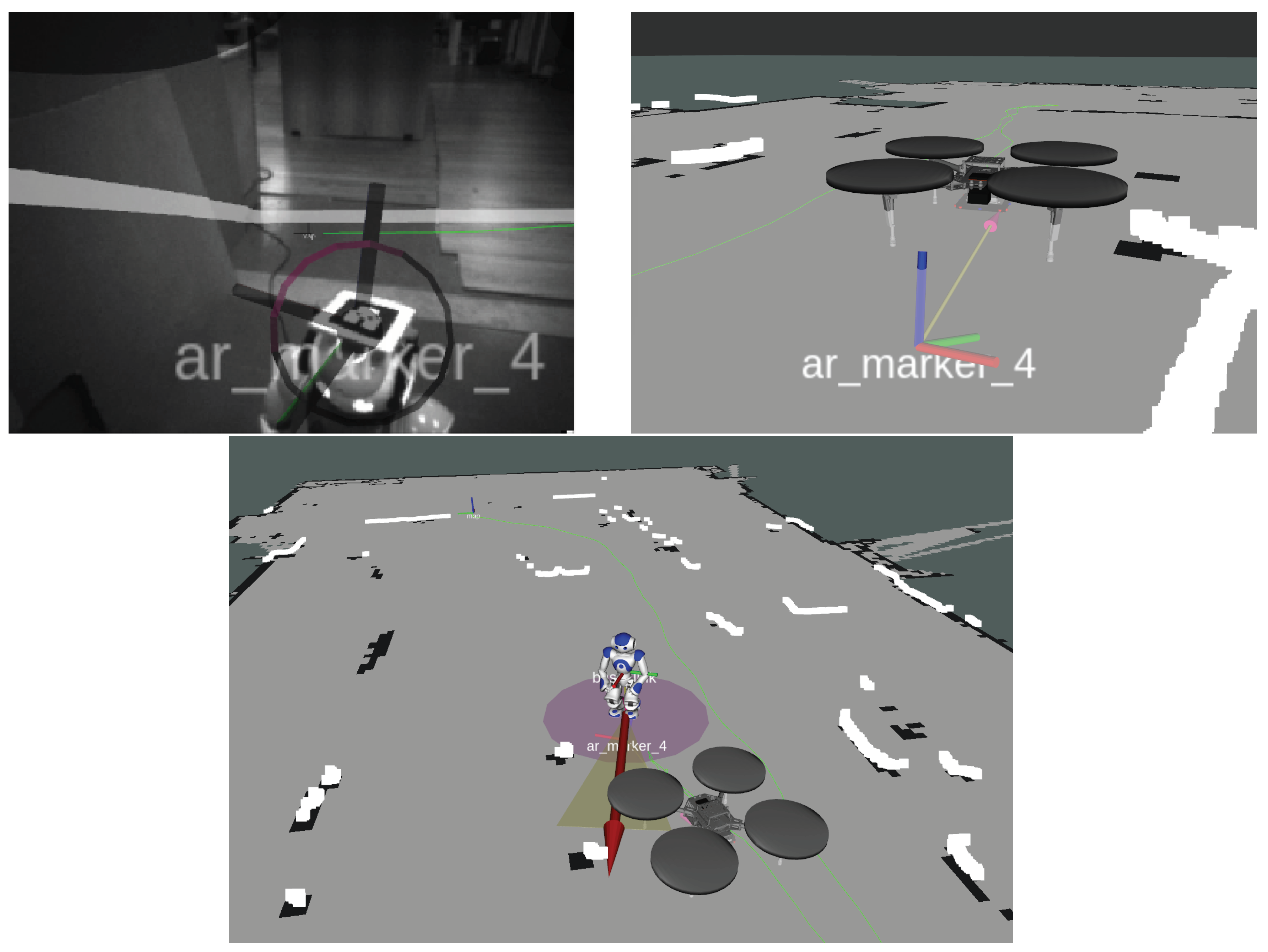
During the UAV navigation and 3D mapping, it also searches for the ground robot in the unknown area under consideration. The detection is performed by using an ALVAR AR [33] marker, which is placed on a custom-made mount on the robot’s head, as shown in Figure 2. Thus, by utilizing a single camera of the downward stereo camera rig of the Guidance system, marker detection procedure is applied in order to locate the ground humanoid robot in the environment.
Because a resolution camera is used, a 10cm size square marker is adequate for successful detection from several meters. The estimated marker pose, as given by the ALVAR ROS node, is expressed in the camera optical frame coordinate system, and, thus, can be described in any onboard UAV coordinate system. Because the marker is placed on the ground robot’s head, it can be matched with its head frame pose, since it is rigidly stabilized on its head. Thus, during the UAV localization and mapping procedure, if the ground robot is located, it is approximated relative to the UAV pose and, thus, it is georeferenced in respect with the generated map coordinate system. This transformation is defined as
Each matrix in Equation (5) represents a transformation matrix that maps points from coordinate system b to coordinate system a. Specifically, stands for the head marker frame, is the camera’s optical frame, is the camera’s body frame, is the UAV center mass point frame, and is the map coordinate frame. Hence, by applying the transformation in Equation (5), the map position of the ground robot’s head can be calculated, moving gradually from the marker to the camera lens, to the camera body, to the UAV center, to the map. Specifically, any point is mapped, as follows:
where the point is in map coordinates. Because we are projecting the robot pose on the planar map coordinate system, we only acquire its x and y values. Figure 8 shows the marker’s pose projection on the map’s planar frame.
The ground robot’s initial pose is published as a geometry_msgs/PoseWithCovarianceStamped ROS message, consisting of the current timestamp, the estimated robot pose in the map coordinate system (position:, and orientation in quaternion form:), and a covariance matrix that is initialized by a Gaussian distribution. Figure 8 shows the steps for registering the Nao pose in the map coordinate system during the UAV flight.
3.7. Space Transformation and Ground Robot Positioning
Objective: track ground robot pose into the generated 3D map by fusing data from the UAV (Figure 1, end of third column).
Because the ground robot is not equipped with any mapping sensor, despite its odometry data, there is a need for aerial assistance through the UAV vision in order to help it with the localization. As the ground humanoid robot navigates along complicated paths, translational and rotational errors may occur, thus its final pose estimation distribution will be highly uncertain. Consequently, the odometry data alone are not sufficient for accurately localizing the robot in the given map.
For this reason, the ground robot position is approximated as perceived from the air, by georeferencing it according to the current UAV’s position in the generated 2.5D map. Thus, the adaptive Monte Carlo Localization (MCL, KLD-sampling) approach has been used to approximate the ground robot position in the generated map by accumulating information from its 2D position along with the SLAM map and the 3D constructed map (with respect to the ground robot height). This approach uses an adaptive particle filter to track the ground robot pose, which changes continuously as the ground robot navigates in the area.
3.8. Path Planning with a Foot Planner
Objective: perform obstacle-free path planning for the ground robot using UAV generated data (Figure 1, beginning of fourth column).
Because we have obtained a sufficient representation of the surrounding environment on the occupancy grid map and the humanoid robot is localized, the succeeding step is to perform the exploration and the search for individuals in need. Under the initial assumption that the ground robot cannot make any spatial measurements, likewise, the UAV cannot perform human detection. Thus, the ground robot is responsible for performing human detection during its navigation in the unknown environment.
In order to realize path planning for the humanoid robot, the search-based FootStep planner [34] has been utilized, which estimates the most appropriate FootStep path from the robot’s current position to a given target in the map coordinate system. Specifically, this path planning approach implements the R* search algorithm, which is a variant of A*, with an Euclidean heuristic function to extract optimal navigation paths. The R* algorithm combines weighted A* searches in a local deterministic search with a randomized component and, thus, provides a speed-up to the search procedure.
In the meantime, the NAOqi software features a walking engine that uses a linear inverted pendulum model in order to generate stable gaits. This walking engine, despite the direct omnidirectional velocity control for commanding the Nao to walk to a target position, features a FootStep command functionality. The FootStep action is parameterized by a displacement of the moving foot relative to the stance foot. Thus, by implementing a specific module to bridge the FootStep planner with the humanoid FootStep command functionality, the humanoid robot can parse and execute stepping commands, described in the format of humanoid_nav_msgs/StepTarget ROS messages.
3.9. Human Detection
Objective: perform visual human detection on the ground robot (Figure 1, end of fourth column).
Convolutional neural networks are utilized in a plethora of applications, especially in robotic fields, for example, in robot motion, task coordination, robotic perception, and more. Object detection and recognition algorithms deal with the detection and the localization of an object in the camera frame and its classification in one of the known classes/labels. The current detection systems generally start by extracting a set features from the input images and then use classifiers or localizers to identify the objects in the feature space. These systems perform detection either through a sliding window scan over the image or by focusing on selected regions.
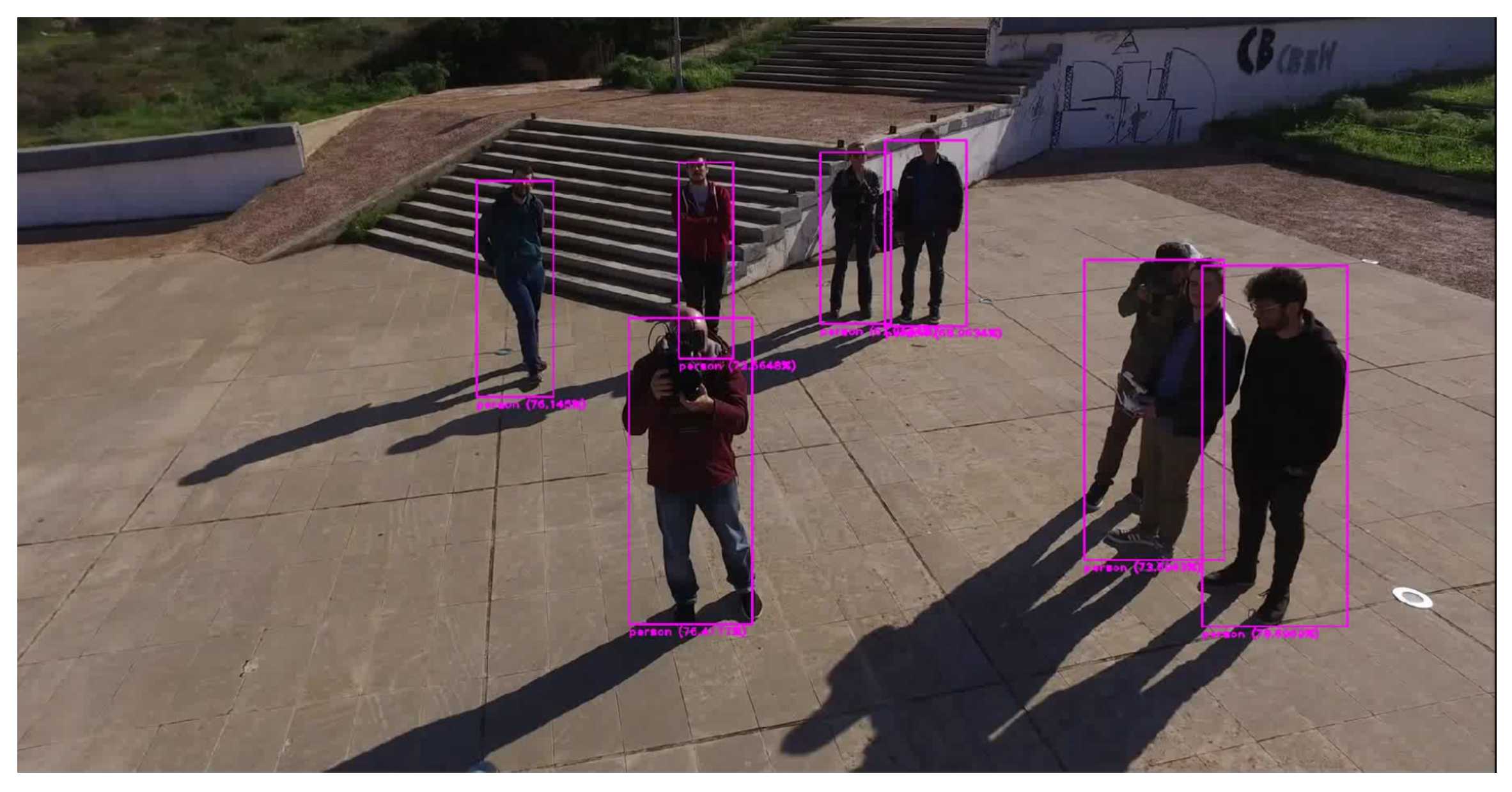
To deal with the human detection problem, we are using a unified object detector system, the YOLO [35], which has been extensively applied to real-time robotic vision applications since 2015, when it was published [36]. The YOLO system is based on a single convolutional neural network, developed with the Darknet open-source framework [37], which predicts the bounding boxes of detected objects in the image frame and the class probabilities for those boxes, simultaneously. Unlike most object detection systems that use classifiers for detection, YOLO frames the detection problem through a regression approach. By design, this system uses the entire image information during training and testing, so it learns a variety of object representations in the observed camera scenes, as each image has different contextual information.
Under the current study, we utilized the Darknet open-source framework in order to train a new YOLO neural network, based on a given human imagery dataset. Because initial YOLO applications were based on the Pascal VOC training dataset, we used the VOC2012 dataset [38] and gathered all of the photos that contained humans. For the training procedure, a dedicated input file was created, which included the positive regions of interest of the appeared human areas, in the required form of () and pre-trained convolutional weights were used as provided by the Darknet website [39]. Figure 9 shows an example of multiple human detection on a single image while using the trained network.
4. Case Study Demonstration
In order to demonstrate the described methodology, a case study is presented, portraying an outdoor scene in an urban environment within our university campus. The UAV flies over occluded areas, trying to reconstruct the 3D scene and localize itself and the ground robot, that searches for humans. The search area is about 30 by 30 m, including buildings, roadways, and vegetation. The UAV flies in varying altitudes, ranging from 3 to 10 m in order to detect the ground robot’s (10 × 10) cm marker. Even though most of the experiments were conducted in outdoor environments, in some cases, for demonstration reasons, additional indoor/outdoor results are presented to showcase the applicability of the proposed procedure under various environments.
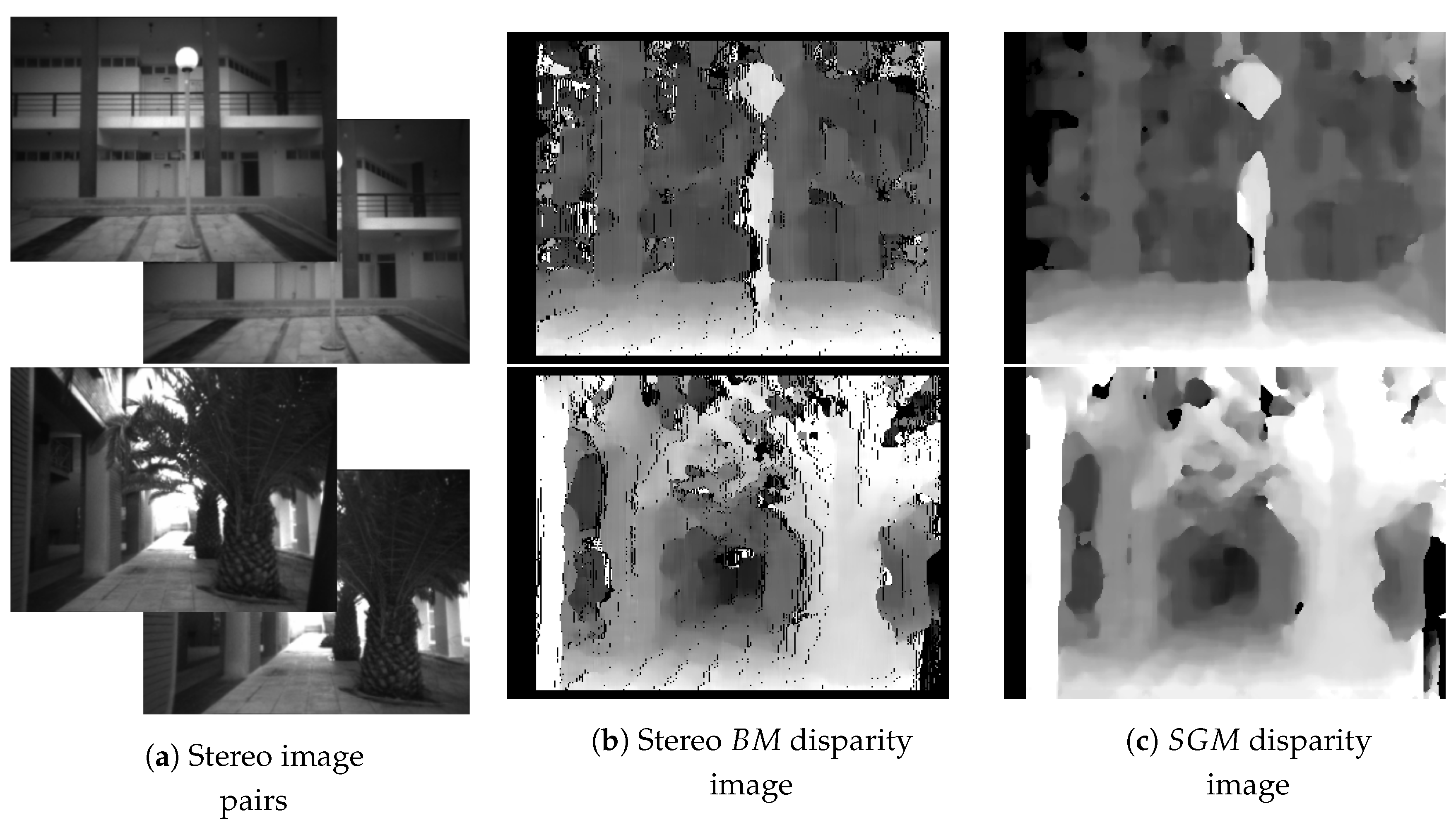
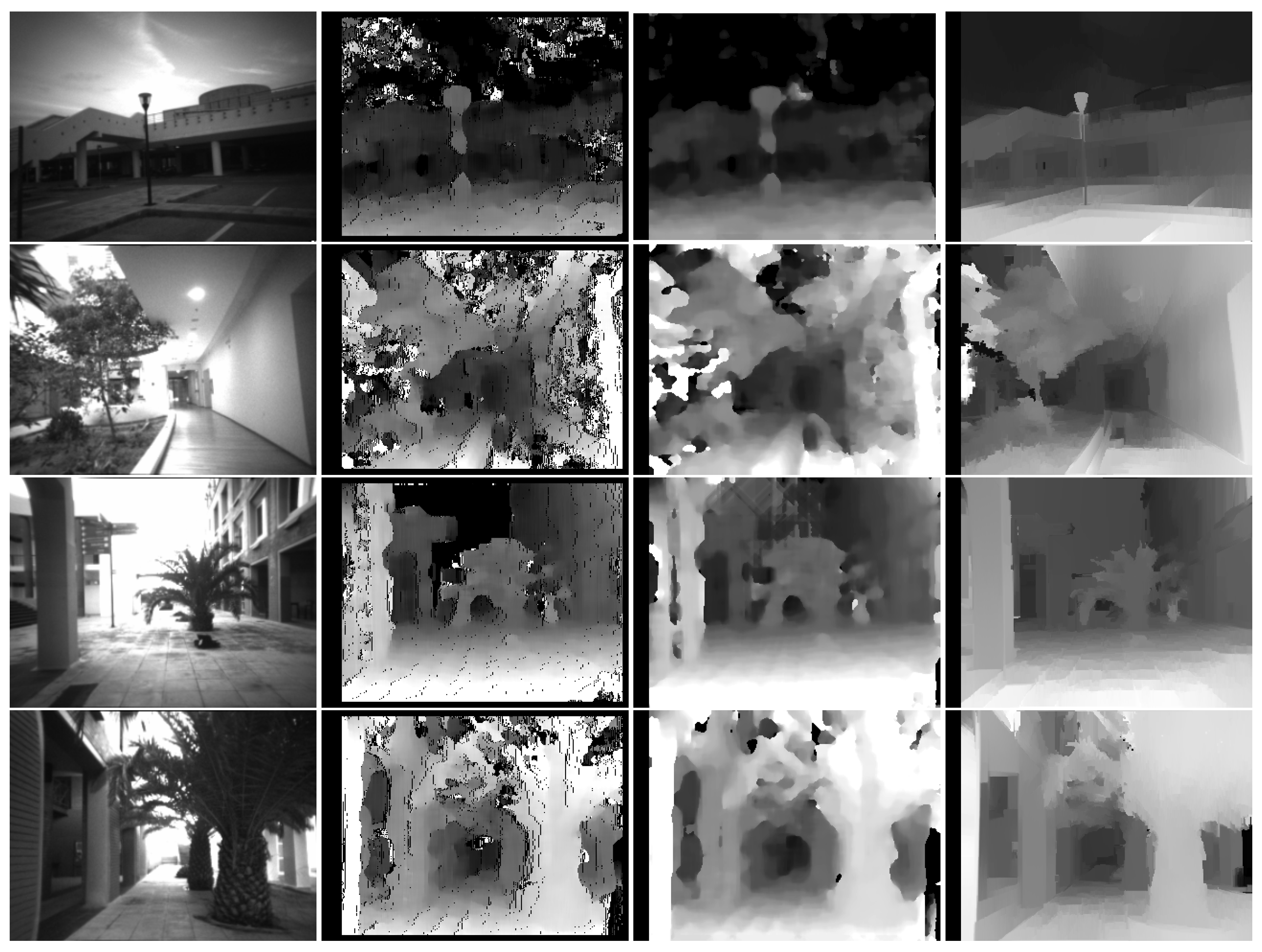
Figure 10b,c show the results of Stereo BM and SGM algorithms, given the stereo image pairs shown in Figure 10a. The resulting disparity images delivered by the stereo BM algorithm were produced while using 16 levels of depth resolution and by matching blocks of 13 pixels, in contrast to blocks of one pixel, which is selected by default in the Stereo BM algorithm. Additionally, none of the pre- or post- processing methods are applied (i.e., Sobel pre-filtering, speckle filtering). All of the processes are conducted in real time and on board.
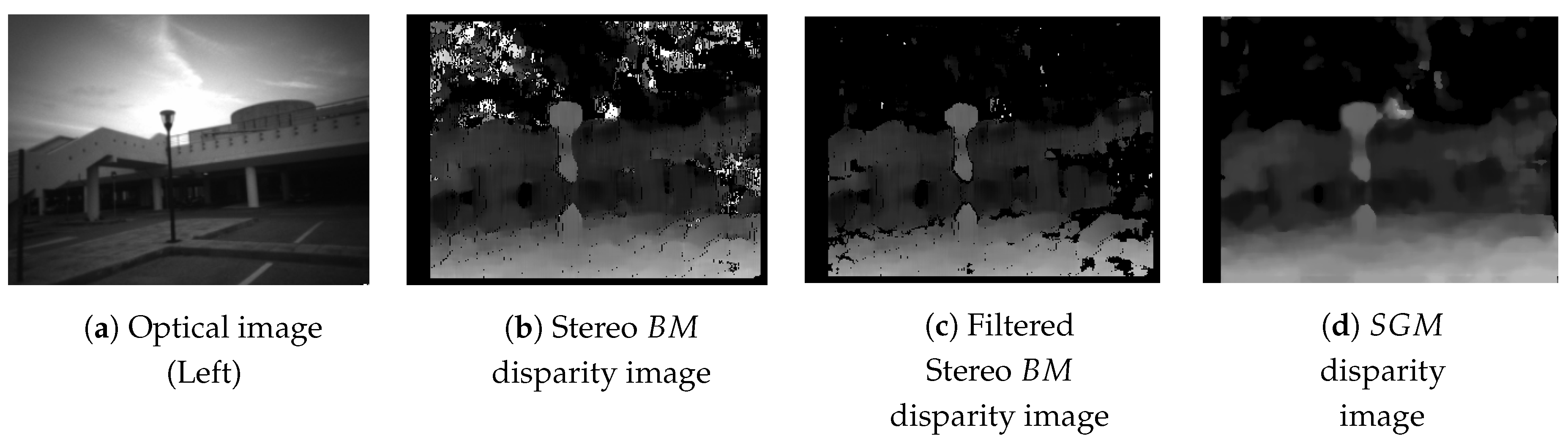
In most cases, as shown in Figure 11, Stereo BM produces disparity discontinuities (Figure 11b), at low-texture detailed image regions, due to the algorithm’s local-cost behavior. The uniqueness ratio parameter may filter some discontinuities (Figure 11c) by adjusting the winner-takes-all cost function margin in the disparity computation; nevertheless, it cannot overcome the SGM results (Figure 11d).
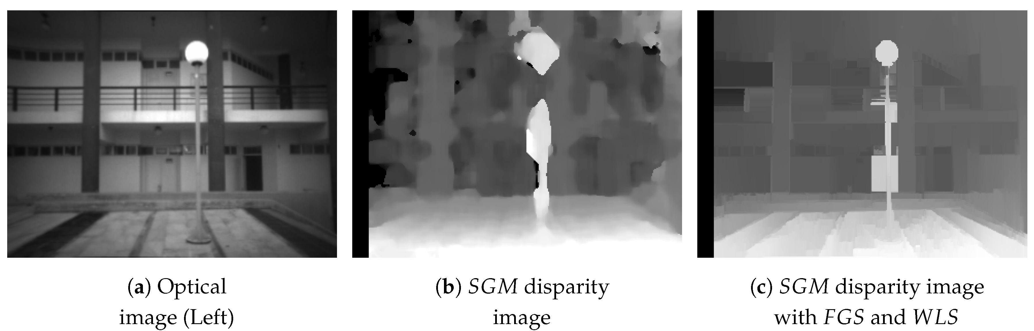
Figure 12 and Figure 13 show some examples from real-world DJI Guidance camera’s captures and the disparity images after WLS-filter application, as compared with the aforementioned stereo matching processes. The distances of the sensors to the mapped area spans from 2 to 12 m, while a 5 m threshold is set for the data that were used to construct the 3D map. It is noteworthy that the WLS filter defines a one-dimensional smoothing parameter , which resembles the amount of regularization during the filtering iterations and enables variance tuning for setting filtering sensitiveness to guidance image adaptation. In our experiments, we used a higher value for when compared to the proposed one to preserve extreme situations, in which the SGM approach gives a more uniform disparity map by fading important spatial information.
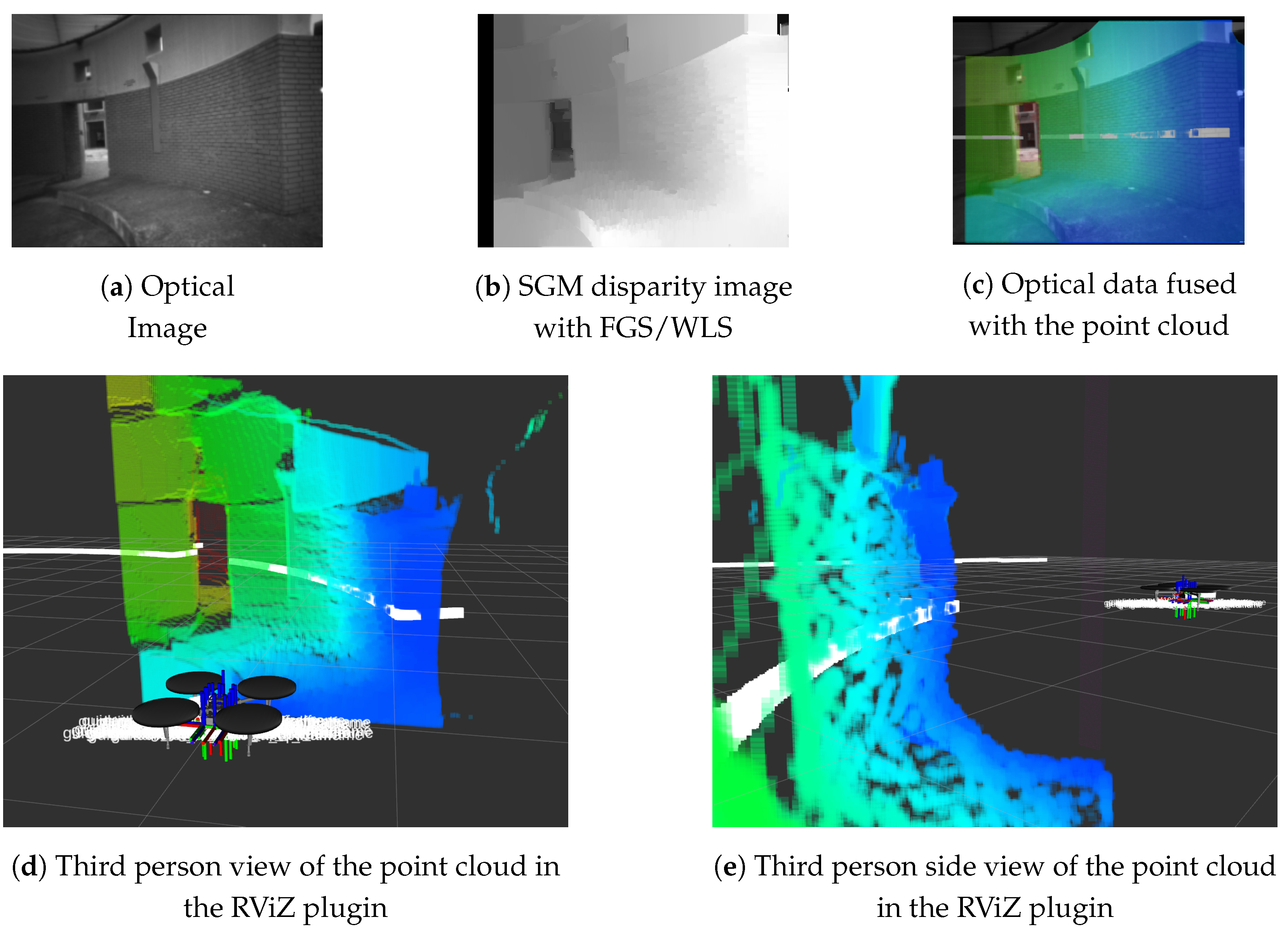
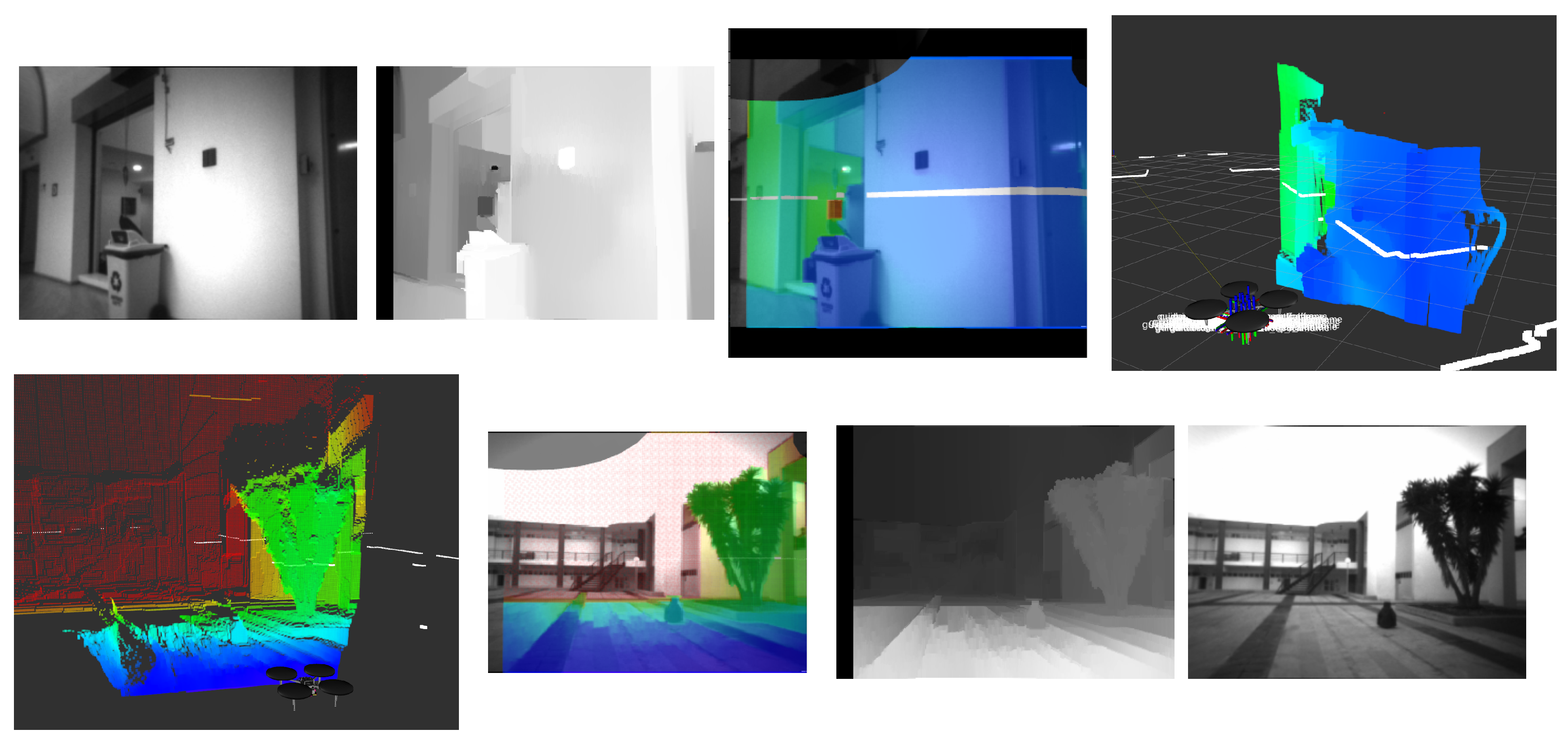
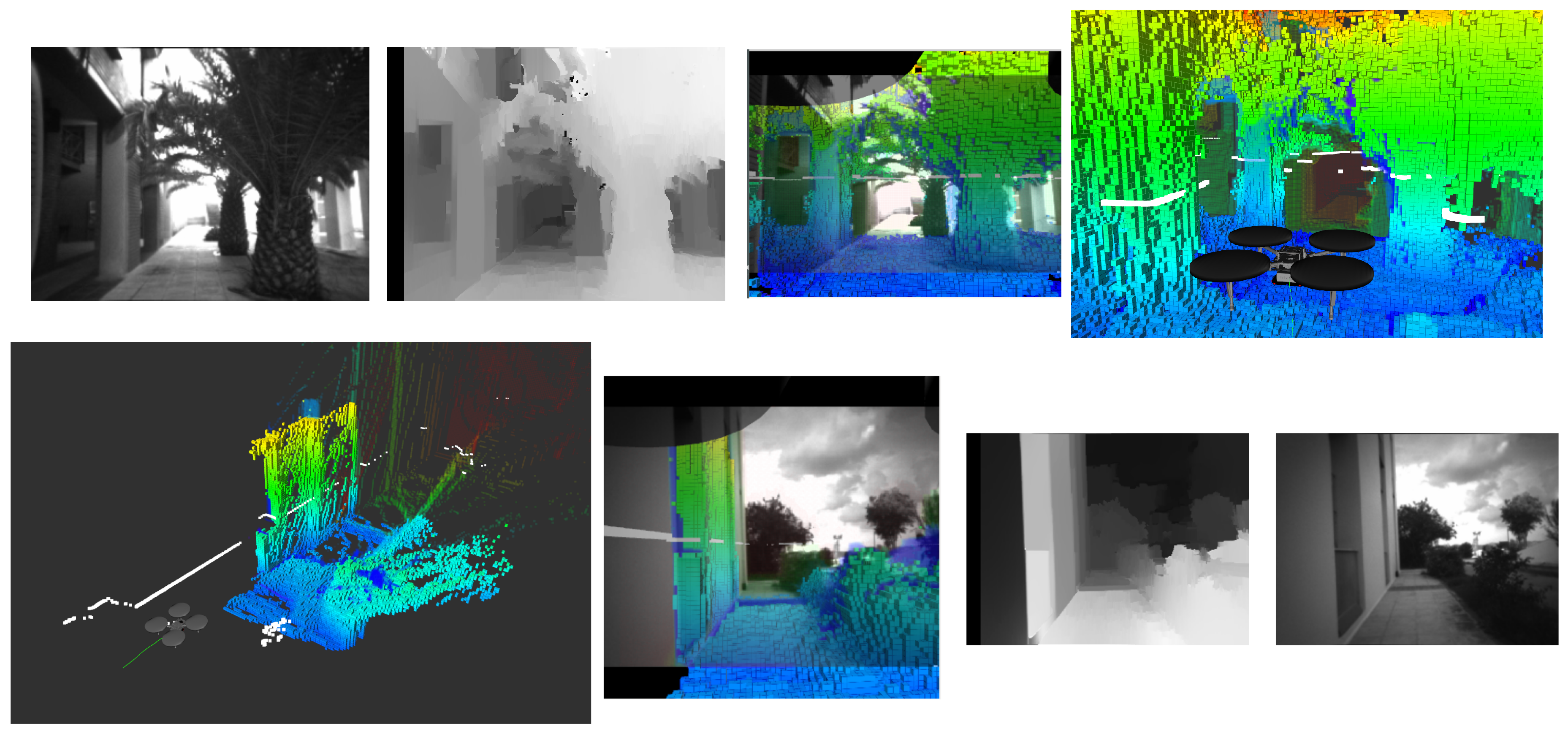
Figure 14 illustrates the depth map transformation to a point cloud data structure, as it appears in the RViZ tool. The white line (spheres) represents the LiDAR scanned endpoints. Figure 14c shows the fusion of the left camera’s scene view and point cloud. The point cloud data appear aligned to the optical camera’s data, because they are expressed in the left camera’s coordinate system. Figure 14d,e show the point cloud data in third person perspective. Additionally, Figure 15 shows more real-world examples in indoor and outdoor environments. LiDar mapping provides a distance accuracy of a few cm, while the 3D image mapping varies, according to the distance of the sensor to the mapped objects, and it reaches up to 60 cm.
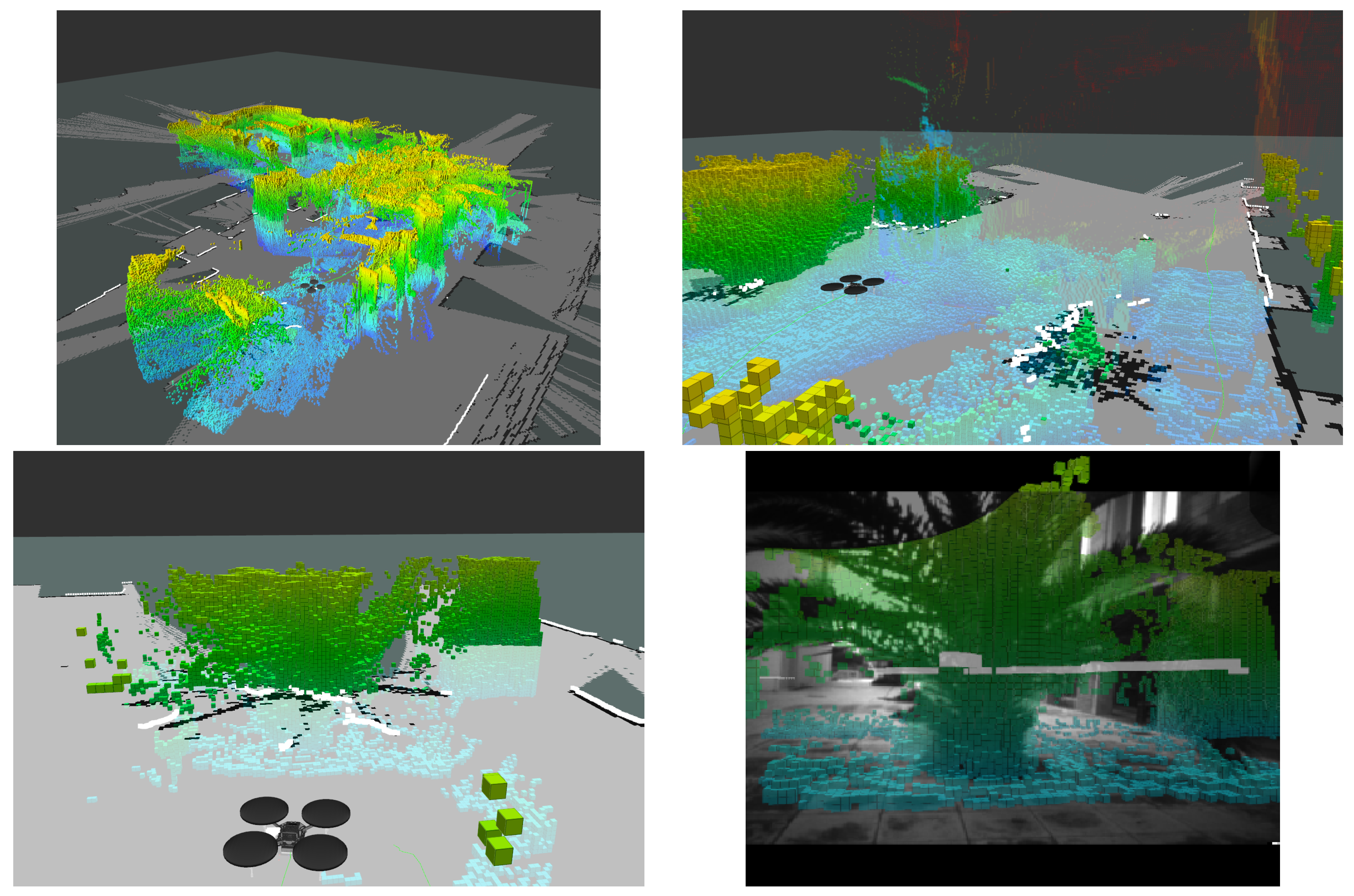
The OctoMap framework was integrated in the UAV’s mapping approach and tested under various indoor and outdoor mapping scenarios (Figure 16). The OctoMap library can be used with all kinds of distance sensors, as long as the inverse sensor model is available, and, thus, we employed a beam-based inverse sensor model that was based on the front stereo camera system. Consequently, we assume that the left camera of the front stereo camera system with its extracted point cloud (expressed in its optical frame) is considered to be a 3D LiDAR sensor with its 3D laser scan point cloud. Specifically, given the extracted point cloud from the front cameras’ stereo matching process, we assume that each calculated 3D point measurement corresponds to an obstacle’s surface that was taken from the line of sight between the sensor origin (left camera optical frame origin) and the endpoint.
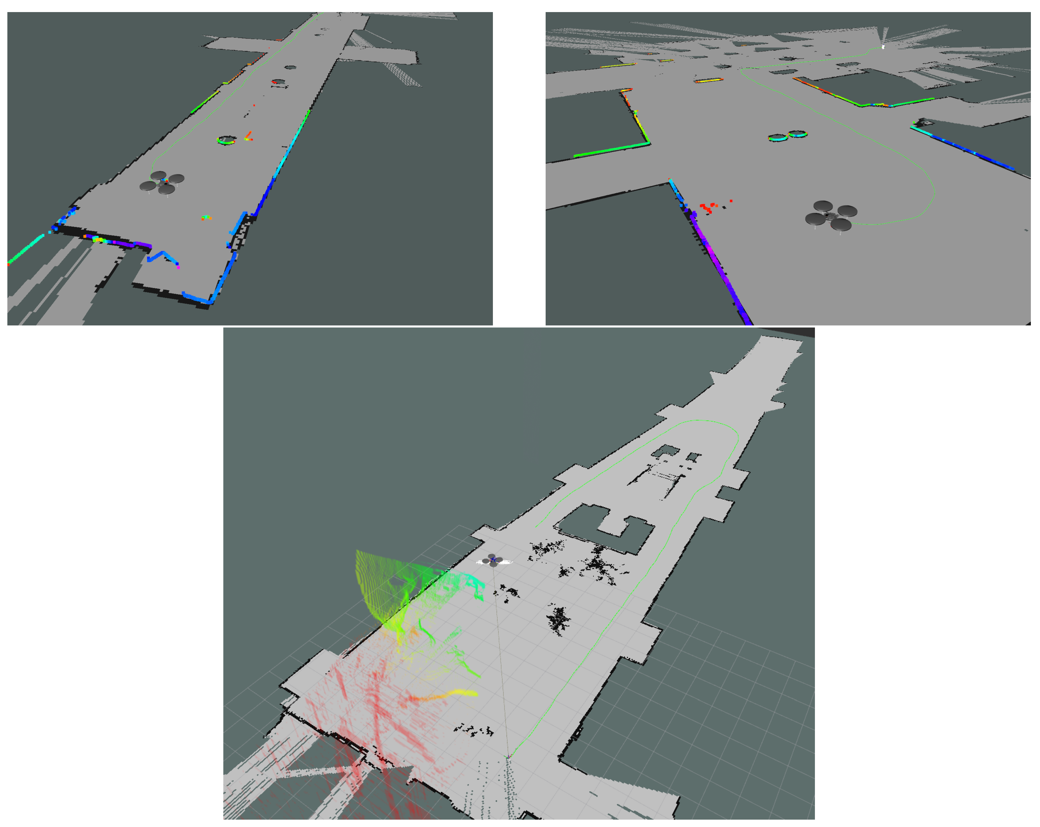
Figure 17 shows UAV mapping and localization procedures, in different operating environments. As the UAV navigates, it keeps a stable altitude level, and, thus, the resulting 2D map is estimated relative to this altitude value.
Because the 2D map is obtained and the pose becomes known and the UAV localized, the OctoMap mapping data can be fused to construct the final 3D map. So, given the UAV poses and the corresponding spatial captures, the maps are referenced in the same coordinate system and thus a final fused map is generated. Figure 18 show simultaneous 2D and 3D mapping applications, as they contribute to a shared map frame.
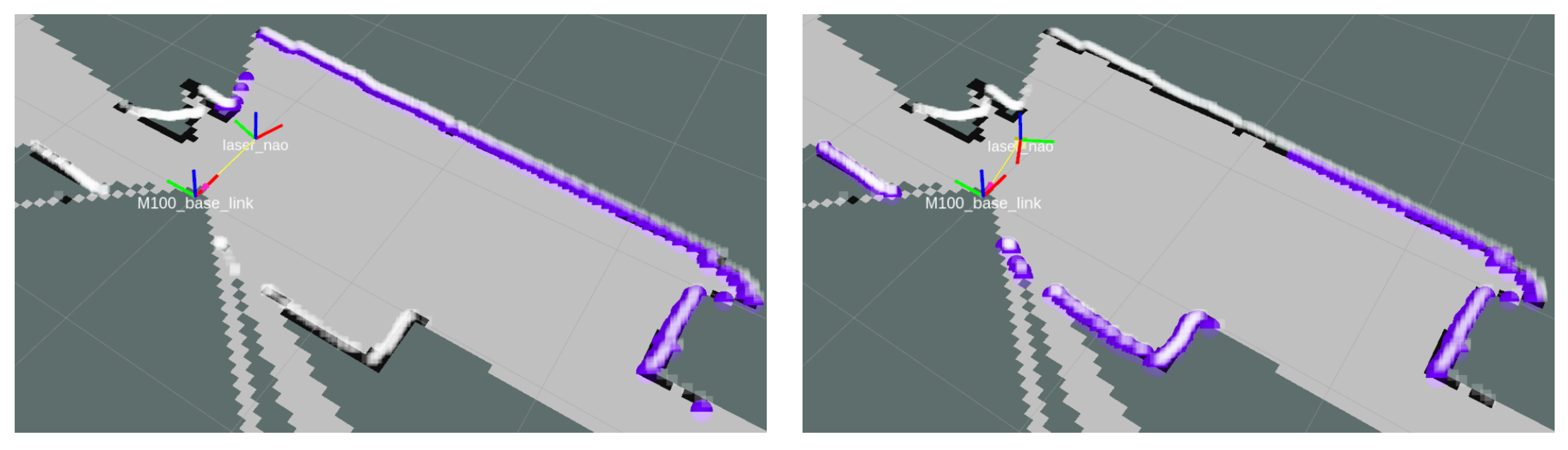
Overall, this module creates laser scan endpoints for the Nao robot with respect to the 2.5D generated map, in order to be included in the MCL estimation, and thus, to the Nao’s positioning within the area. Each time the UAV updates its pose belief in the 3D map and has an optical view of the ground robot, it proceeds with the creation of distance measurements for the ground robot, according to their relative position and orientation. The generated LiDAR data are taken from the 2.5D map, which is created according to the 3D constructed map and ground robot’s height. Hence, given the relative poses of the two robots, the ground robot has continuous access to ranging data with respect to its own body, although, in reality, they are generated by the UAV in the air. The positional accuracy of the ground robot is about 30 cm. Figure 19 shows the generation of the laser scan range data in various Nao’s head poses, along with the M100’s body frame.
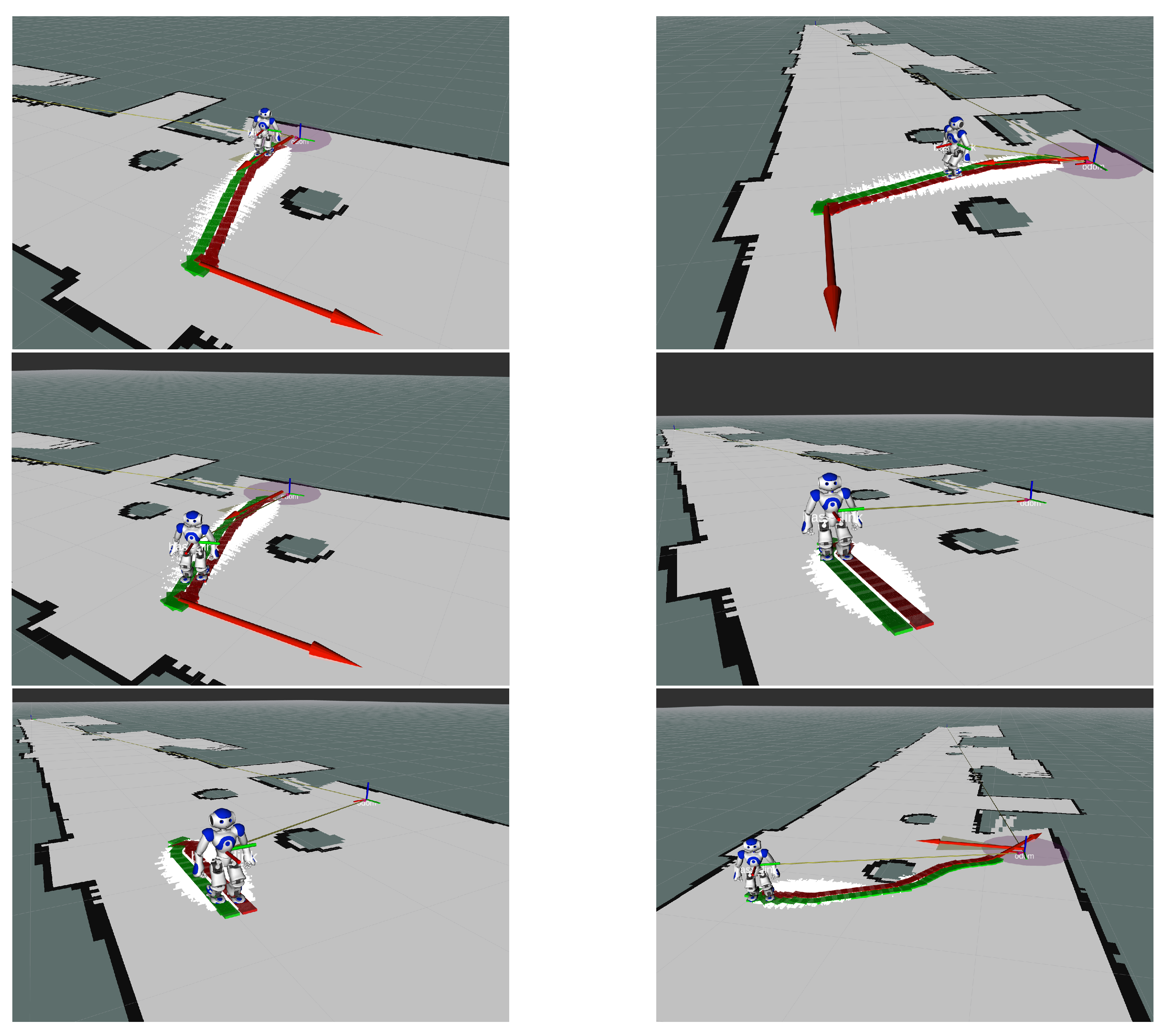
Next, the FootStep planner was tested in various world situations and provided effective and obstacle-free paths for the humanoid robot to follow. The experiment setting included the ground robot that covered from five to ten meters. Again, the process it terms of time was seamless. The robot throughout its path, used its head mounted image sensors to scan and search for humans. Figure 20 shows an example of Nao’s FootStep navigation procedure.
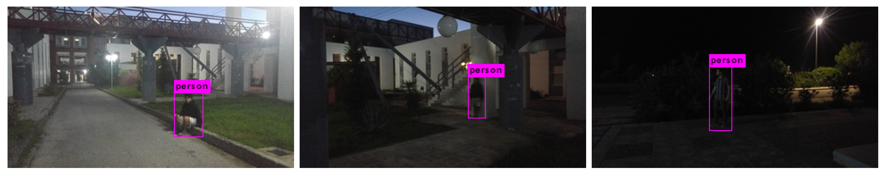
The final step of human detection includes the neural network, tested on Nao’s camera footage and on typical mobile camera footage, and it sufficiently detected individuals, despite their appearance in groups (as in Figure 9) or under low-light environmental conditions (as in Figure 21). This is actually the last step of the procedure, which succeeded in detecting and approaching the human in the scene. It is noted that all of the UAV related processes were conducted on-board the aerial robot. Furthermore, all of the algorithms were executed in real time and, thus, the bottleneck of the procedure in terms of time was the actual movement of the robots. The remotely guided UAV scanned the given test area in less than 5 min. and estimated the ground robot position from an altitude of 4 m based on the ground robot’s marker size. The ground robot needed a few minutes to follow the estimated path and scan for humans. The times varied, depending on human placement and the initial position of the ground robot, but all of the tests were conducted in the range of three to ten minutes.
5. Discussion and Conclusions
This study describes a ground-aerial robot collaboration approach, in which a UAV and humanoid robot cooperate to solve a real-world Search and Rescue scenario. Assuming that the humanoid robot cannot take any range measurements to localize itself in the world, we use the UAV to perform both the environment mapping and humanoid robot localization. The M100 UAV uses a combination of SLAM and OctoMap approaches to extract a 2.5D occupancy grid map, specifically made for the humanoid robot navigation. As the humanoid robot is initially localized in the map frame, it is assigned a goal position to reach and a parameterized FootStep planner performs the required path planning. An adaptive MCL approach is used for the humanoid robot localization, given its odometry data and the particularly spatial transformed UAV’s LiDAR range data. Finally, a pre-trained convolutional Darknet neural network is used in order to perform human detection, on the way to its target position. Each system part is presented in detail and the overall integrated system is validated with real-world experiments.
The entire project has been implemented within the Robot Operating System (ROS). It is noted that the proposed integrated methodology is based on several restrictive assumptions to make the problem more demanding, including the assumption that the ground robot has no way to map its surroundings and the UAV has restricted view of the possible human victims. The above described problem setting can include more variations and each proposed step may be substituted with alternative algorithmic approaches, yet the proposed integration shows the overall potential of robot collaboration as a proof-of-concept solution. A possible Search and Rescue scenario may include an earthquake that has considerably changed an urban area, so that no supportive maps are available. The UAV may perform the alleged mapping in 3D, thus providing this information to ground robots that may have no sensors to make their own localization, navigation, and/or mapping, or the environment could be severely occluded, thus restraining the ground robots from navigating autonomously.
When considering implementation issues, the use of a stereo camera when compared to a 3D LiDAR system for 3D world perception could be a cheaper solution, but it requires fine tuning for satisfactory results. The proposed stereo matching to 3D map reconstruction pipeline was specifically selected and adjusted to work with the given guidance hardware system and to able to perform onboard the UAV in real-time situations. In our approach, all of the processes are executed on the Manifold’s quad-core ARM processor and there is no use of the embedded NVIDIA graphics processor, which supports the CUDA parallel computing platform. Especially in machine vision applications, algorithms are implemented with respect to parallelism, so that they can be executed on graphic processor units and take advantage of their multi-core specifications. Thus, importing and adjusting the used stereo matching and post-filter algorithms to work with Manifold’s GPU will yield better onboard runtimes through less memory consumption. Additionally, it is noteworthy that an upgraded Guidance system could also aid in obtaining better 3D world reconstructions, as the stereo matching algorithms tend to perform better on higher image resolutions.
In our approach, despite the semi-autonomous humanoid robot behavior (for example, it only awaits for a target position and map data to proceed with the exploration), the UAV is guided by the human rescue team, which monitors the current map status along with the sensor measurements to ensure sufficient area coverage through a safe flight. Accordingly, an ideal scenario would implement a fully-autonomous UAV that could decide to follow specific paths in the unknown environment to maximize its knowledge about the external world and then inform the ground robot accordingly.
Additionally, given the implemented SLAM approach, a FastSLAM exploration method could be applied, which computes the future estimates of control sequences and trades off path uncertainty versus map uncertainty when evaluating such control sequences. FastSLAM exploration techniques are tested in wide-area robotic exploration scenarios, by which the robots tend to visit unknown terrains in order to enrich the map state, and other times lead back to previously mapped areas in order to improve their pose estimates. A diversity of control policies and strategies could be designed and implemented by also combining the located position of the humanoid robot in the map frame.
In conclusion, the present study reveals the potential of robot-to-robot and human-to-robot collaboration in Search and Rescue applications through a proof-of-concept integration. Possibly, the most important lesson learned from this project is that data fusion and sharing between robots can overcome their own inherent limitations, which enables them to accomplish complex missions as a team.
Author Contributions
Conceptualization, M.G.L. and D.C.; Methodology, M.G.L., D.C. and P.P.; Resources, M.G.L. and P.P.; Software, D.C.; Supervision, M.G.L. and P.P.; Validation, D.C. and M.G.L.; Visualization, D.C. and M.G.L.; Writing—original draft, D.C.; Writing—review and editing, M.G.L. and P.P.; Funding acquisition, P.P. All authors have read and agreed to the published version of the manuscript.
Funding
This research was partially supported by the European Union and Greek national funds through the Operational Program Competitiveness, Entrepreneurship and Innovation, under the call RESEARCH—CREATE—INNOVATE (project code: T1EDK-03209).
Acknowledgments
We would like to acknowledge the Editors of the journal Drones, MDPI for their invitation to submit this study along with their kind support.
Conflicts of Interest
The authors declare no conflict of interest.
References
- Loose, H.; Zasepa, A.M.; Pierzchala, P.; Ritter, R. GPS Based Navigation of an Autonomous Mobile Vehicle. Solid State Phenom. 2009, 147–149, 55–60. [Google Scholar] [CrossRef]
- Hamid, M.H.A.; Adom, A.H.; Rahim, N.A.; Rahiman, M.H.F. Navigation of mobile robot using Global Positioning System (GPS) and obstacle avoidance system with commanded loop daisy chaining application method. In Proceedings of the 5th International Colloquium on Signal Processing and its Applications, Kuala Lumpur, Malaysia, 6–8 March 2009; pp. 176–181. [Google Scholar]
- Loose, H. Autonomous mobile robots for outdoor tasks. Mechanika 2007, 68, 70–73. [Google Scholar]
- Malyavej, V.; Kumkeaw, W.; Aorpimai, M. Indoor robot localization by RSSI/IMU sensor fusion. In Proceedings of the 10th IEEE International Conference on Electrical Engineering/Electronics, Computer, Telecommunications and Information Technology, Krabi, Thailand, 15–17 May 2013; pp. 1–6. [Google Scholar]
- Biswas, J.; Veloso, M. WiFi localization and navigation for autonomous indoor mobile robots. In Proceedings of the IEEE International Conference on Robotics and Automation, Anchorage, AK, USA, 3–7 May 2010; pp. 4379–4384. [Google Scholar]
- Hou, X.; Arslan, T. Monte Carlo localization algorithm for indoor positioning using Bluetooth low energy devices. In Proceedings of the IEEE International Conference on Localization and GNSS (ICL-GNSS), Nottingham, UK, 27–29 June 2017; pp. 1–6. [Google Scholar]
- Liu, C.; Cheng, Z.; Zhang, Y.; Wang, G. An indoor positioning system based on RFID with rotating antenna and passive tags. In Proceedings of the 2nd IEEE International Conference on Robotics and Automation Engineering (ICRAE), Shanghai, China, 29–31 December 2017; pp. 455–459. [Google Scholar]
- Olszewski, B.; Fenton, S.; Tworek, B.; Liang, J.; Yelamarthi, K. RFID positioning robot: An indoor navigation system. In Proceedings of the IEEE International Conference on Electro-Information Technology (EIT), Rapid City, SD, USA, 9–11 May 2013; pp. 1–6. [Google Scholar]
- Xing, B.; Zhu, Q.; Pan, F.; Feng, X. Marker-Based Multi-Sensor Fusion Indoor Localization System for Micro Air Vehicles. Sensors 2018, 18, 1706. [Google Scholar] [CrossRef] [PubMed] [Green Version]
- Chen, W.; Zhang, T. An indoor mobile robot navigation technique using odometry and electronic compass. Int. J. Adv. Robot. Syst. 2017, 14, 1729881417711643. [Google Scholar] [CrossRef] [Green Version]
- Chen, C.; Chai, W.; Nasir, A.K.; Roth, H. Low cost IMU based indoor mobile robot navigation with the assist of odometry and Wi-Fi using dynamic constraints. In Proceedings of the 2012 IEEE/ION Position, Location and Navigation Symposium, Myrtle Beach, SC, USA, 23–26 April 2012; pp. 1274–1279. [Google Scholar]
- Huang, A.S.; Bachrach, A.; Henry, P.; Krainin, M.; Maturana, D.; Fox, D.; Roy, N. Visual Odometry and Mapping for Autonomous Flight Using an RGB-D Camera. In Robotics Research; Christensen, H.I., Khatib, O., Eds.; Springer International Publishing: Cham, Switzerland, 2017; pp. 235–252. [Google Scholar]
- Grzonka, S.; Plagemann, C.; Grisetti, G.; Burgard, W. Look-ahead Proposals for Robust Grid-based SLAM with Rao-Blackwellized Particle Filters. Int. J. Robot. Res. (IJRR) 2009, 28, 191–200. [Google Scholar] [CrossRef] [Green Version]
- Grzonka, S.; Grisetti, G.; Burgard, W. Towards a navigation system for autonomous indoor flying. In Proceedings of the IEEE International Conference on Robotics and Automation, Kobe, Japan, 12–17 May 2009; pp. 2878–2883. [Google Scholar]
- Kohlbrecher, S.; von Stryk, O.; Meyer, J.; Klingauf, U. A flexible and scalable SLAM system with full 3D motion estimation. In Proceedings of the IEEE International Symposium on Safety, Security, and Rescue Robotics, Kyoto, Japan, 1–5 November 2011; pp. 155–160. [Google Scholar]
- Ruangpayoongsak, N.; Roth, H.; Chudoba, J. Mobile robots for search and rescue. In Proceedings of the IEEE International Safety, Security and Rescue Rototics, Workshop, Kobe, Japan, 6–9 June 2005; pp. 212–217. [Google Scholar]
- Guarnieri, M.; Kurazume, R.; Masuda, H.; Inoh, T.; Takita, K.; Debenest, P.; Hodoshima, R.; Fukushima, E.; Hirose, S. HELIOS system: A team of tracked robots for special urban search and rescue operations. In Proceedings of the IEEE/RSJ International Conference on Intelligent Robots and Systems, St. Louis, MO, USA, 10–15 October 2009; pp. 2795–2800. [Google Scholar]
- Reid, R.; Cann, A.; Meiklejohn, C.; Poli, L.; Boeing, A.; Braunl, T. Cooperative multi-robot navigation, exploration, mapping and object detection with ROS. In Proceedings of the 2013 IEEE Intelligent Vehicles (IV) Symposium, Gold Coast, Australia, 23–26 June 2013; pp. 1083–1088. [Google Scholar]
- Luo, C.; Espinosa, A.P.; Pranantha, D.; Gloria, A.D. Multi-robot search and rescue team. In Proceedings of the IEEE International Symposium on Safety, Security, and Rescue Robotics, Kyoto, Japan, 1–5 November 2011; pp. 296–301. [Google Scholar]
- Lee, C.E.; Im, H.J.; Lim, J.M.; Cho, Y.J.; Sung, T.K. Seamless Routing and Cooperative Localization of Multiple Mobile Robots for Search and Rescue Application. ETRI J. 2015, 37, 262–272. [Google Scholar] [CrossRef] [Green Version]
- Quigley, M.; Conley, K.; Gerkey, B.P.; Faust, J.; Foote, T.; Leibs, J.; Wheeler, R.; Ng, A.Y. ROS: An open-source Robot Operating System. In Proceedings of the ICRA Workshop on Open Source Software, Kobe, Japan, 12–17 May 2009. [Google Scholar]
- Gouaillier, D.; Blazevic, P. A Mechatronic Platform, The Aldebaran Robotics Humanoid Robot. In Proceedings of the 32nd Annual Conference on IEEE Industrial Electronics (IECON), Paris, France, 6–10 November 2006; pp. 4049–4053. [Google Scholar]
- ROS—NaoQi. Available online: https://github.com/ros-naoqi (accessed on 18 December 2020).
- Matrice 100—Quadcopter for Developers. Available online: https://www.dji.com/gr/matrice100 (accessed on 18 December 2020).
- DJI Onboard SDK ROS 4.0.1. Available online: https://github.com/dji-sdk/Onboard-SDK-ROS (accessed on 18 December 2020).
- Foote, T. tf: The transform library. In Proceedings of the IEEE International Conference on Technologies for Practical Robot Applications (TePRA), Woburn, MA, USA, 22–23 April 2013; pp. 1–6. [Google Scholar]
- Konolige, K. Small Vision Systems: Hardware and Implementation. In Robotics Research; Shirai, Y., Hirose, S., Eds.; Springer: London, UK, 1998; pp. 203–212. [Google Scholar]
- Hirschmuller, H. Stereo Processing by Semiglobal Matching and Mutual Information. IEEE Trans. Pattern Anal. Mach. Intell. 2008, 30, 328–341. [Google Scholar] [CrossRef] [PubMed]
- Farbman, Z.; Fattal, R.; Lischinski, D.; Szeliski, R. Edge-preserving Decompositions for Multi-scale Tone and Detail Manipulation. ACM Trans. Graph. 2008, 27, 1–10. [Google Scholar] [CrossRef]
- Min, D.; Choi, S.; Lu, J.; Ham, B.; Sohn, K.; Do, M. Fast global image smoothing based on weighted least squares. IEEE Trans. Image Process. 2014, 23, 5638–5653. [Google Scholar] [CrossRef] [PubMed]
- Rusu, R.B.; Cousins, S. 3D is here: Point Cloud Library (PCL). In Proceedings of the IEEE International Conference on Robotics and Automation (ICRA), Shanghai, China, 9–13 May 2011; pp. 1–4. [Google Scholar]
- Hornung, A.; Wurm, K.; Bennewitz, M.; Stachniss, C.; Burgard, W. OctoMap: An efficient probabilistic 3D mapping framework based on octrees. Auton. Robot. 2013, 34, 189–206. [Google Scholar] [CrossRef] [Green Version]
- Augmented Reality/3D Tracking. 2019. Available online: http://virtual.vtt.fi/virtual/proj2/multimedia/index.html (accessed on 18 December 2020).
- Hornung, A.; Dornbush, A.; Likhachev, M.; Bennewitz, M. Anytime search-based footstep planning with suboptimality bounds. In Proceedings of the 12th IEEE-RAS International Conference on Humanoid Robots, Osaka, Japan, 29 November–1 December 2012; pp. 674–679. [Google Scholar]
- Redmon, J.; Farhadi, A. YOLOv3: An Incremental Improvement. 2018. Available online: http://arxiv.org/abs/1804.02767 (accessed on 18 December 2020).
- Redmon, J.; Divvala, S.; Girshick, R.; Farhadi, A. You Only Look Once: Unified, Real-Time Object Detection. 2015. Available online: http://arxiv.org/abs/1506.02640 (accessed on 18 December 2020).
- Redmon, J. Darknet: Open Source Neural Networks in C. 2016. Available online: http://pjreddie.com/darknet (accessed on 18 December 2020).
- Everingham, M.; Van Gool, L.; Williams, C.K.I.; Winn, J.; Zisserman, A. The Pascal Visual Object Classes (VOC) challenge. Int. J. Comput. Vis. 2010, 88, 303–338. [Google Scholar] [CrossRef] [Green Version]
- Redmon, J. ImageNet Classification. 2016. Available online: https://pjreddie.com/darknet/imagenet (accessed on 18 December 2020).
Figure 1.
Overview of the architecture of the collaborative approach.

Figure 2.
The Aldebaran Nao humanoid robot.

Figure 3.
The DJI Matrice 100 quadcopter equipped with the Manifold unit and the Light Detection and Ranging (LiDAR) sensor.
Figure 3.
The DJI Matrice 100 quadcopter equipped with the Manifold unit and the Light Detection and Ranging (LiDAR) sensor.

Figure 4.
The Hokuyo UTM-30LX-EW LiDAR.

Figure 5.
Hokuyo UTM-30LX-EW diagram of scanned area and specifications.

Figure 6.
Image processing: Semi-Global Matching (SGM) disparity maps generation and post-processing with Fast Global Smoother (FGS) and Weighted Least-Squares (WLS).
Figure 6.
Image processing: Semi-Global Matching (SGM) disparity maps generation and post-processing with Fast Global Smoother (FGS) and Weighted Least-Squares (WLS).

Figure 7.
The volumetric and tree representation of an octree, that stores free (shaded white) and occupied (black) cells. Image from Hornung et al. [32].
Figure 7.
The volumetric and tree representation of an octree, that stores free (shaded white) and occupied (black) cells. Image from Hornung et al. [32].

Figure 8.
Locating and initializing Nao pose in the map frame.

Figure 9.
Detecting humans as appeared in groups.

Figure 10.
Disparity images calculated with Stereo BM and SGM methods.

Figure 11.
Disparity images calculated with (filter) Stereo BM and SGM methods. The darker areas represent larger disparity values and thus indicate farther distances.
Figure 11.
Disparity images calculated with (filter) Stereo BM and SGM methods. The darker areas represent larger disparity values and thus indicate farther distances.

Figure 12.
Disparity map enhancement with WLS-filter application.

Figure 13.
Examples of up-sampling disparity images with post-filtering. Images from left to right: optical from stereo pair, Stereo disparity, disparity, disparity with .
Figure 13.
Examples of up-sampling disparity images with post-filtering. Images from left to right: optical from stereo pair, Stereo disparity, disparity, disparity with .

Figure 14.
Point cloud generation from stereo matching and depth extraction procedures. The pseudo-color of the points indicate their distance from the stereo camera module.
Figure 14.
Point cloud generation from stereo matching and depth extraction procedures. The pseudo-color of the points indicate their distance from the stereo camera module.

Figure 15.
Indoor (top, left-to-right) and outdoor (bottom, right-to-left) point cloud generation.

Figure 16.
Optical feed to point cloud to octree mapping pipeline. The height is visualized by a simple color coding and the white line (small spheres) illustrates the LiDAR scan endpoints.
Figure 16.
Optical feed to point cloud to octree mapping pipeline. The height is visualized by a simple color coding and the white line (small spheres) illustrates the LiDAR scan endpoints.

Figure 17.
Generated maps using the Hector SLAM system on the M100 quadcopter.

Figure 18.
Fusing both 3D octree map and 2D SLAM map.

Figure 19.
Transformed laser scan endpoints for the Nao, according to its relative pose to the M100.
Figure 19.
Transformed laser scan endpoints for the Nao, according to its relative pose to the M100.

Figure 20.
Nao navigation in known environment, while using the FootStep planner Robot Operating System (ROS) node.
Figure 20.
Nao navigation in known environment, while using the FootStep planner Robot Operating System (ROS) node.

Figure 21.
Darknet neural network use under low-light environment conditions.

Publisher’s Note: MDPI stays neutral with regard to jurisdictional claims in published maps and institutional affiliations. |
© 2020 by the authors. Licensee MDPI, Basel, Switzerland. This article is an open access article distributed under the terms and conditions of the Creative Commons Attribution (CC BY) license (http://creativecommons.org/licenses/by/4.0/).
Share and Cite
MDPI and ACS Style
Chatziparaschis, D.; Lagoudakis, M.G.; Partsinevelos, P. Aerial and Ground Robot Collaboration for Autonomous Mapping in Search and Rescue Missions. Drones 2020, 4, 79. https://0-doi-org.brum.beds.ac.uk/10.3390/drones4040079
AMA Style
Chatziparaschis D, Lagoudakis MG, Partsinevelos P. Aerial and Ground Robot Collaboration for Autonomous Mapping in Search and Rescue Missions. Drones. 2020; 4(4):79. https://0-doi-org.brum.beds.ac.uk/10.3390/drones4040079
Chicago/Turabian StyleChatziparaschis, Dimitrios, Michail G. Lagoudakis, and Panagiotis Partsinevelos. 2020. "Aerial and Ground Robot Collaboration for Autonomous Mapping in Search and Rescue Missions" Drones 4, no. 4: 79. https://0-doi-org.brum.beds.ac.uk/10.3390/drones4040079