Safety Enhancement of UAVs from the Signal Processing’s Perspectives: A Bird’s Eye View


Signal Processing, Inc., Rockville, MD 20850, USA
Drones 2021, 5(1), 16; https://0-doi-org.brum.beds.ac.uk/10.3390/drones5010016
Submission received: 20 January 2021
/
Revised: 15 February 2021
/
Accepted: 22 February 2021
/
Published: 26 February 2021
(This article belongs to the Special Issue Feature Papers of Drones)
Abstract
:Unmanned air vehicles (UAVs) or drones have gained popularity in recent years. However, the US Federal Aviation Administration (FAA) is still hesitant to open up the national air space (NAS) to UAVs due to safety concerns because UAVs have several orders of magnitude of more accidents than manned aircraft. To limit the scope in this paper, we focus on large, heavy, and expensive UAVs that can be used for cargo transfer and search and rescue operations, not small radio-controlled toy drones. We first present a general architecture for enhancing the safety of UAVs. We then illustrate how signal processing technologies can help enhance the safety of UAVs. In particular, we provide a bird’s eye view of the application of signal processing algorithms on condition-based maintenance, structural health monitoring, fault diagnostics, and fault mitigation, which all play critical roles in UAV safety. Some practical applications are used to illustrate the importance of the various algorithms.
1. Introduction
The use of unmanned aerial vehicles (UAV) in the military and industry today is becoming more and more widespread. However, perhaps due to lower manufacturing standards and budget limitations, the mishap rates in unmanned aerial vehicles (UAVs) are several orders of magnitude greater than manned aviation [1]. Considering these high mishap rates, the US Department of Transportation’s Federal Aviation Administration (FAA) has initiated several programs and partnerships to enhance the safety and reliable operation of UAVs [2].
In this paper, we focus on large, heavy, and expensive (millions of dollars) UAVs such as cargo transport and search and rescue aircraft, not radio-controlled amateur drones. In general, UAV safety can be improved from the following perspectives. First, the UAV manufacturers need to use durable engines and communication equipment and strong structural materials. Reliable communication equipment will ensure drone safety, as a lost link between UAV and ground station is very dangerous [3]. Durable engines and strong materials will ensure reliable flight in rough weather conditions. Second, advanced conditioned-based maintenance (CBM) practice should be deployed [4,5,6]. Compared with traditional periodic preventive maintenance, CBM can be cost-effective but may require additional sensors to monitor some critical components such as the engine. Third, structural health monitoring (SHM) [7,8], especially the non-destructive type of SHM, should be frequently used to monitor cracks, loosened fasteners, etc.
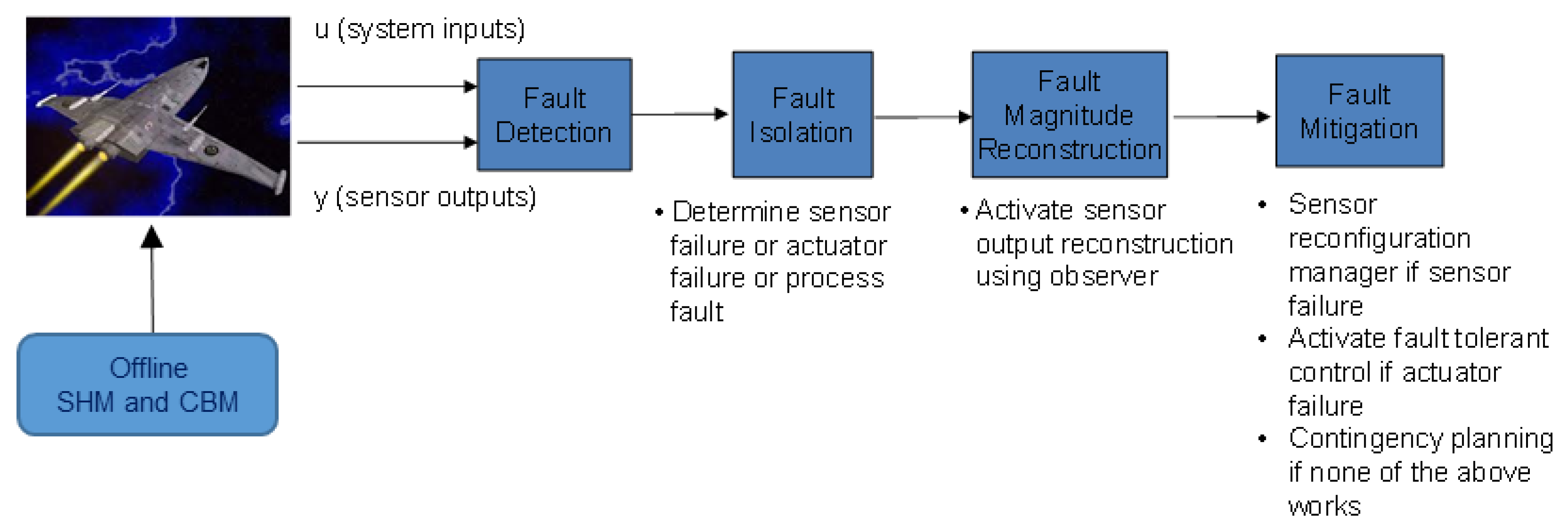
The aforementioned ideas mostly require both hardware and software, and have been routinely used in UAVs to maintain reliability and safety. In addition to the above safety enhancement practices, we would like to emphasize that signal processing algorithms also play important roles in other critical areas. Figure 1 shows the general architecture of an integrated system that can enhance the safety of UAVs. Some monitoring operations such as SHM, CBM, are done off-line on the ground. The off-line process involves data collection and processing. Others such as sensor and actuator fault diagnostic, fault-tolerant control are done online. The sensor’s measurements (angles, speed, etc.) are all collected in real-time and processed in real-time. Contingency planning is done off-line. Moreover, as shown in Figure 1, we can clearly see the use of signal processing algorithms in fault detection, fault isolation, fault magnitude reconstruction, and fault mitigation. First, robust fault diagnosis algorithms [9,10,11,12,13,14,15,16,17,18] perform accurate fault detection and isolation. Failures in sensors and actuators can cause system instability. Diagnosing those faults will improve the overall safety of UAVs. Second, in fault mitigations, robust [19,20,21,22,23] and fault-tolerant controllers [24,25,26,27,28,29,30,31] are also critical for UAV safety. Robust controllers can tolerate some small perturbations in the UAVs due to aging or external disturbances. Fault-tolerant controllers can perform control reconfiguration to directly address sensor and actuator malfunctions during flight. Third, one critical aspect of fault mitigation is contingency planning for engine failures, which is the last line of defense for UAV safety. That is, all the aforementioned practices have been tried, but nothing works and the UAV is eventually on its course to crash due to engine loss. Under such an emergency, the goal of contingency planning is either to help UAV operators to glide the UAV or will make the UAV autonomously land itself to a crashing/ditching site or local airport runway if there is no reliable communication link available. In the case of an emergency due to full loss of thrust, wind plays a critical role with respect to reachability to the emergency landing site [32]. Upon full loss of thrust due to engine failure, because of the wind impact, the UAV may not reach the designated landing site and crash into populated areas causing loss of lives. Thus, the wind impact on reachability needs to be addressed in path planning for engine loss contingencies. It is also important that in the event of an emergency that might happen at high altitudes, the UAV should choose a forced landing path that does not violate no-fly zones or stormy weather air zones not to further complicate the situation.
The contributions of our paper is as follows:
- We provide a bird’s eye view of the importance of signal processing algorithms in enhancing the safety of UAVs.
- In each area, we highlight some recent advances in the literature.
Our paper is organized as follows. In Section 2 and Section 3, we briefly mention CBM and SHM practices. In Section 4 and Section 5, we focus on fault diagnostics and fault magnitude estimation. In Section 6, we address fault mitigation using robust and fault-tolerant controllers. Section 7 discusses the last line of defense: contingency planning for an emergency landing. Finally, some concluding remarks, limitations, and future directions are given in Section 8.
2. Condition Based Maintenance (CBM)
Traditionally, mechanical components such as engines, bearings, and gearboxes are maintained by using preventive maintenance, which performs periodic checks on the components. For example, engine oil for cars is replaced with new oil every three thousand miles or every six months. Preventive maintenance is certainly effective and has been widely used. However, one drawback is that it may not be cost-effective. When a car is not being used frequently, periodic maintenance may be wasteful because the oil quality may still be good.
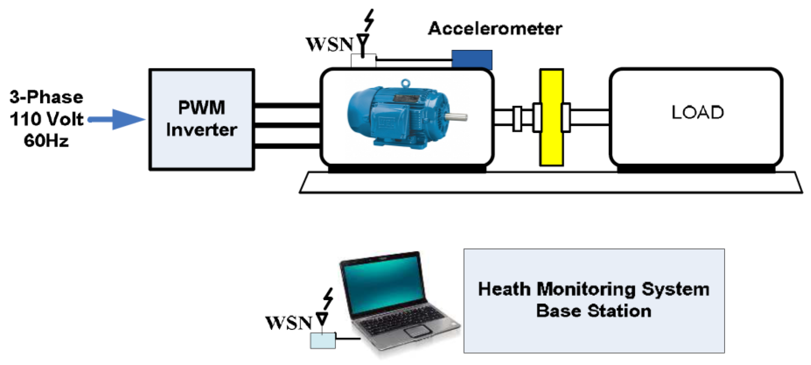
In recent years, people have been advocating condition-based maintenance [33,34], which means some maintenance decisions should be made based on the condition of the component rather than time. Two survey papers [35,36] provided a good review of the relevant works in this area. Some papers have proposed the use of wireless sensor networks (WSN) for quantifying system conditions [37,38]. Figure 2 illustrates how WSN can be used for induction motor monitoring.
It should be noted the Internet of Things (IOT) is also a hot area that can be beneficial to CBM. In [39], some discussions talked about the various applications of IOT in CBM. IOT can also help online fault diagnosis as well.
3. Structural Health Monitoring (SHM)
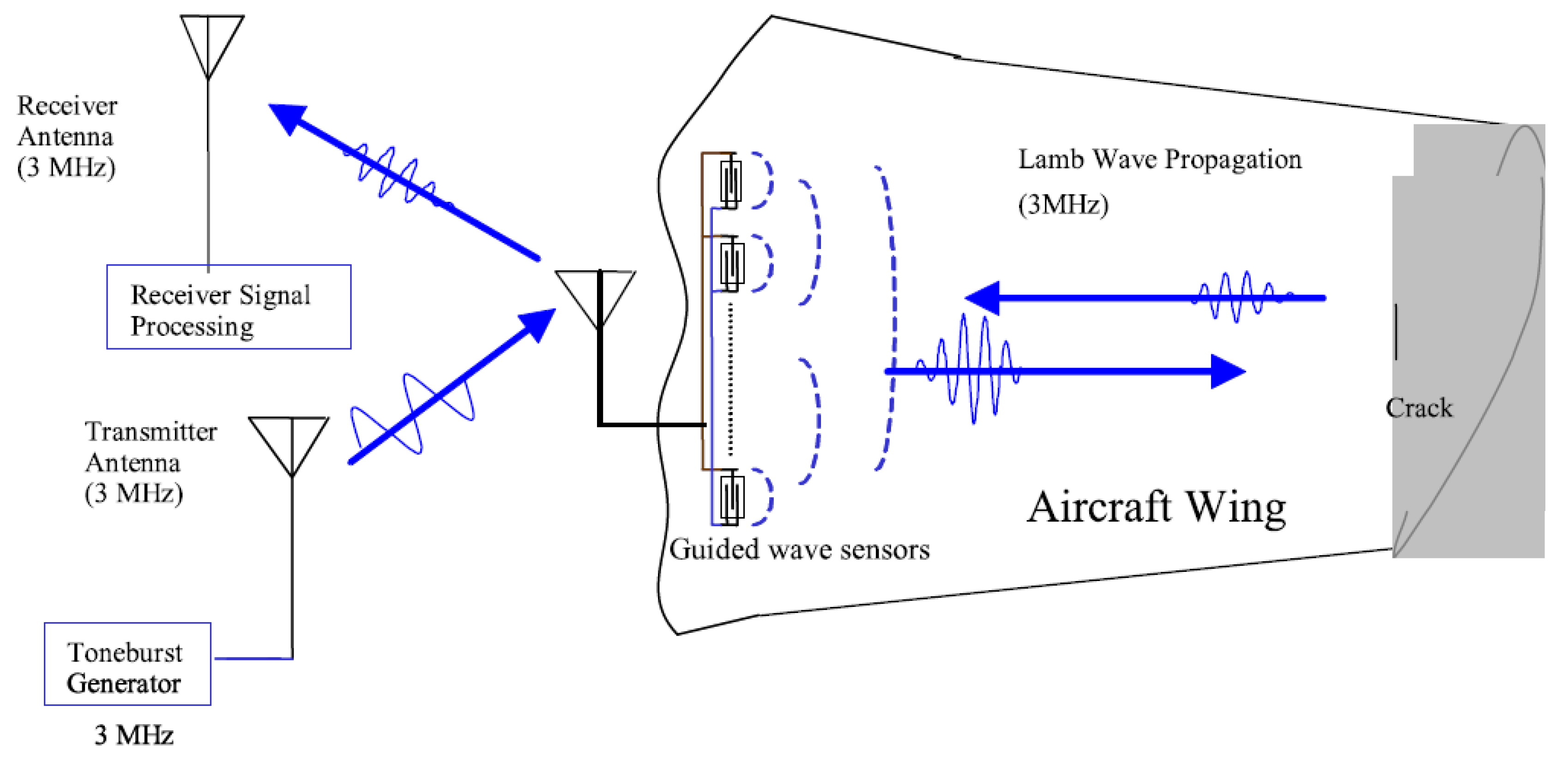
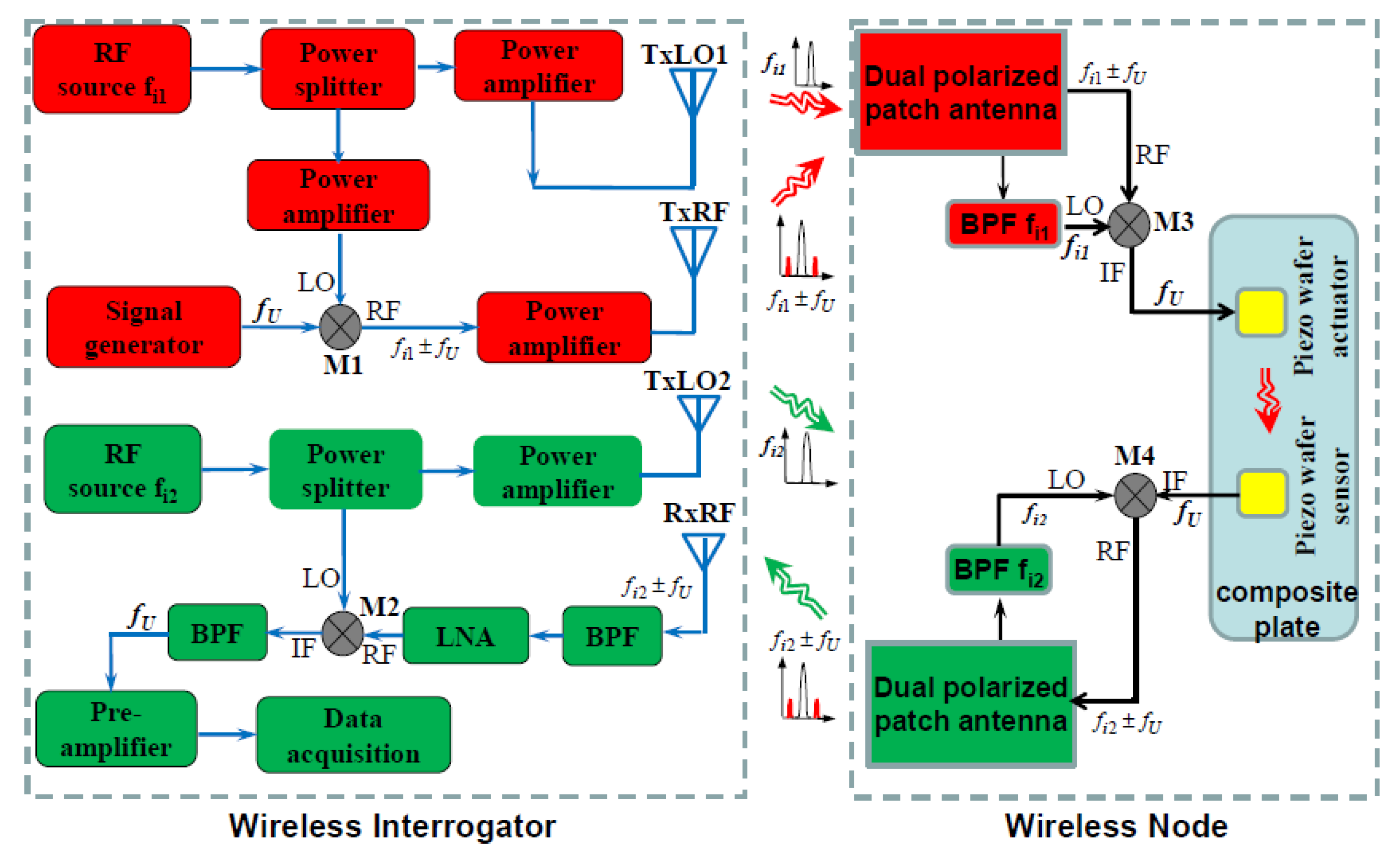
As shown in Figure 3, Structural health monitoring (SHM) [7,8] is one way of nondestructive inspection (NDI). It can be done passively or actively. The purpose is to detect structural defects such as cracks on the wing, loosened bolt, and fasteners, etc.
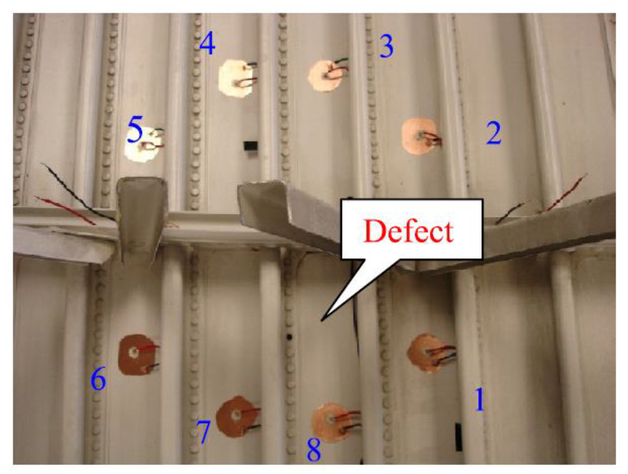
In our opinion, SHM is also one form of CBM. To illustrate the basic idea of SHM, one can refer to Figure 4, which shows an array of sensors/actuators to monitor an aircraft wing panel. Ultrasonic pulses are generated from each sensor, and the rest of the array is receiving the transmitted signals. Once all the sensors are scanned, the collected signals from all the elements will be fed into an algorithm for fault localization. In [8], a RAPID algorithm was developed, which has been widely used in many papers.
4. Sensor and Actuator Fault Diagnostic Algorithms
Sensors and actuators are critical components in complex systems. For instance, in an airplane, effective flight control is impossible if sensors and/or actuators are malfunctioning [41,42]. Sensors and actuators can fail, and their failures have a significant impact on the performance of a system. In the worst case, the failure even can affect the safe operation of the system, leading to a catastrophic event. Sensor failures may include precision degradation, drift, frozen reading, and complete failure [43]. Similarly, actuator failures may include limited range of motion, e.g., valve stiction and complete failure [44]. It is a challenging task to detect sensor and actuator failures [41,42] because sensor outputs contain information from a multitude of sources: normal system outputs, faulty sensor signals, and signals due to noise and external disturbances. Isolating different signals requires the utilization of the input-output relationship of the system. Conventional approaches to increasing the reliability of aircraft systems include installing redundant sensors, which will add more weights, costs, complexity, and most importantly, additional reliability problems.
Given a linear multi-input multi-output (MIMO) system, the inputs, internal states, and outputs can be described by
where , , and , are system inputs, outputs, and internal states, respectively., denote actuator and sensor faults. We would like to detect if the magnitude of is non-zero. If the answer is positive, we have to estimate the magnitude and identify the failure direction matrix . Finally, the magnitudes of failed sensors or actuators will be reconstructed.
Sensor fault detection and diagnosis have been a research topic for decades, and many articles have been published. Interested readers are referred to the survey paper by Frank [45]. While fault detection is relatively easy, isolation of multiple faults is still a challenge to many existing schemes. Recent advances in fault diagnosis use kernel partial least square [46] and nonlinear techniques [47].
5. Sensor Magnitude Reconstruction
After the identification of faulty sensors/actuators, one has to estimate the fault magnitudes. Detailed procedures can be found in [48]. With estimated fault magnitudes, one can correct measurements of the faulty sensors. The measurements in faulty sensors are affected both by the actuator fault and sensor faults In order to get the corrected measurements in faulty sensors, one can design a Kalman filter,
where is the corrected measurement of faulty sensors. A, B, C, D are the system matrices in the state-space model. K is the Kalman gain, are the fault direction matrices [48].
Nowadays, UAV formation (swarm) control practice uses the Real-time Kinematic Global Navigation Satellite System-Inertial Navigation System (RTK-GNSS-INS) [49] for routing and navigation. Moreover, inter-UAV sensors such as Automatic Dependent Surveillance-Broadcast (ADS-B) [50], which provides altitude, aircraft flight ID, and vertical airspeed, have been used in advanced systems. ADS-B reduces the risk of runway collisions, even at night or during heavy rainfall. ADS-B applications being developed now will give pilots indications or alerts of potential collisions. Such systems may be used to dissolve the problem related to faulty sensors.
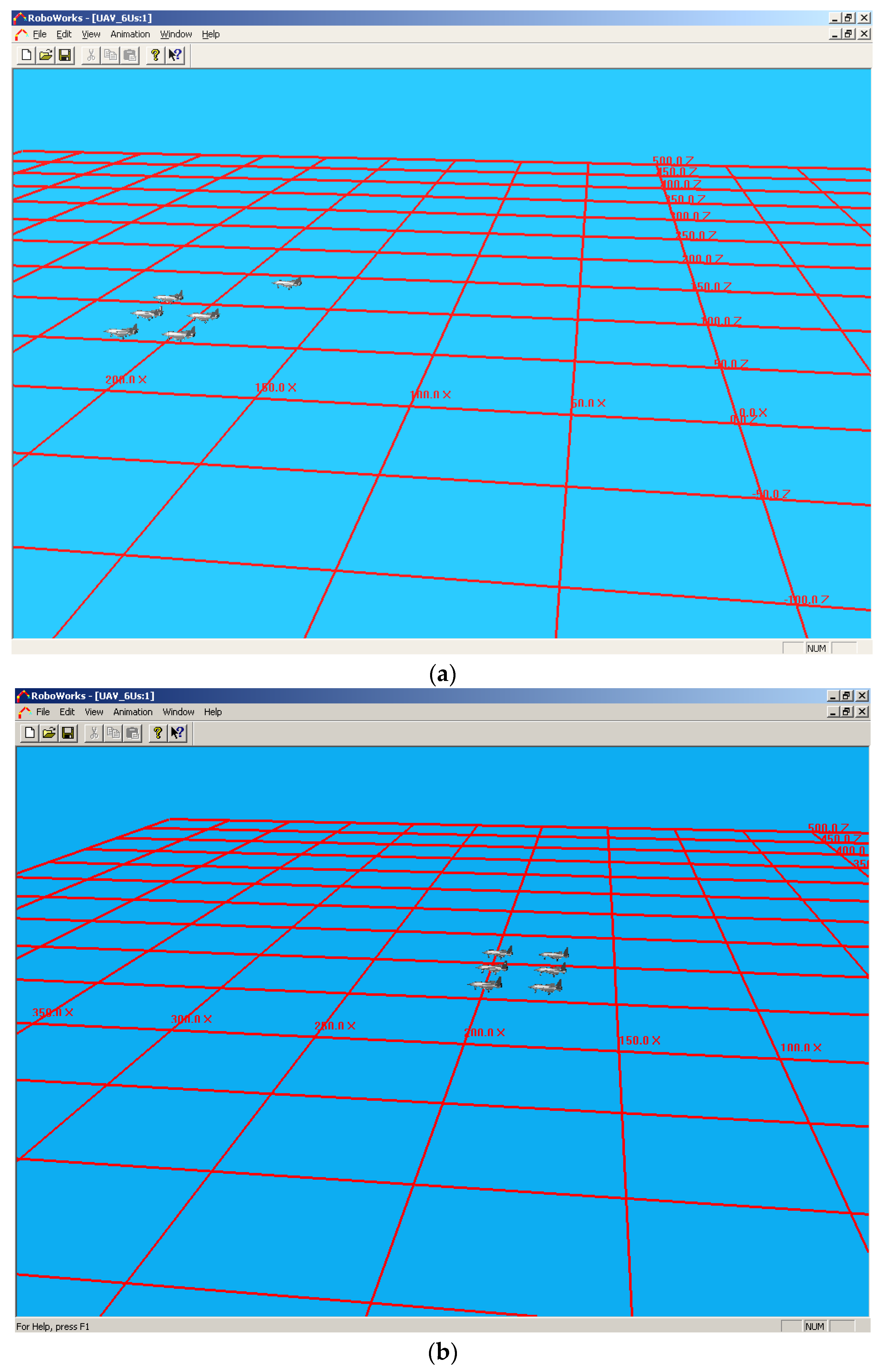
Here we describe some results of detecting GNSS sensor failure and how to use reconstructed sensor information to control the formation of UAVs. We will illustrate the effectiveness of a fault-tolerant formation control algorithm [30] using the rotary UAV developed by UC Berkeley. Two types of formations are considered: mesh and triangle. For each formation, we performed two types of flight: straight flight and 90-degree turning flight. In each case, we assume a fault occurs to the fifth UAV at 10 s. A GNSS/INS (Inertial Navigation System) combination is usually used in UAV navigation systems. In the presence of GNSS failure, the position information provided by the INS will diverge due to error accumulation. Motivated by this observation, the fault model under consideration simulates slowly divergent position measurements. A fault isolation scheme was designed to capture this GNSS failure. Then an observer was designed and used to estimate the positions of the UAV. Figure 6 shows the results, which clearly demonstrated that the reconstruction can still maintain the UAV formation.
6. Robust and Fault-Tolerant Control
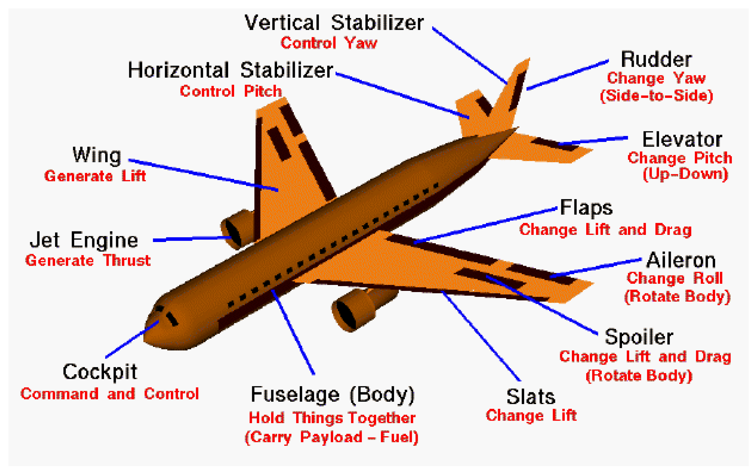
As shown in Figure 7, there can be quite a few actuators for controlling the aircraft. For example, the rudder controls the yaw channel, elevators control the pitch channel, and flaps control the roll channel. From Table 1, we can see that some actuators can be used as secondary actuators for some channels. This shows that different combinations of actuators can serve as backup actuators for different roll, pitch, and yaw channels. In general, fault tolerant control refers to the selection of substitute actuators when primary actuators fail to function.
A robust controller [19,20,21,22,23] can deal with parametric uncertainties to some extent. However, when some faults such as sensor and actuator faults occur, robust controllers are not strong enough to handle such situations. A fault-tolerant controller [24,25,26,27,28,29,30,31] is extremely useful for guaranteeing closed-loop control performance.
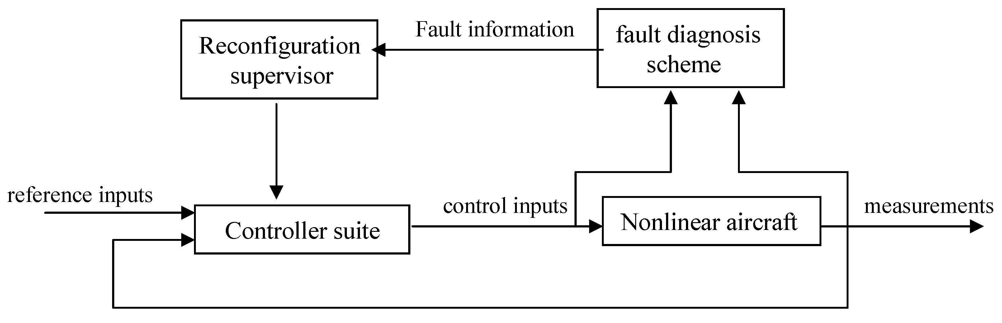
Figure 8 shows a schematic diagram of how fault-tolerant control works. First, a fault diagnosis system that performs on-line fault detection and isolation. Second, a controller suite consists of a primary nominal control system used under normal operating conditions (without faults) and a secondary adaptive fault-tolerant control system engaged only after fault detection. Third, a reconfiguration supervisor makes decisions regarding control system reconfiguration and control reallocation using the fault information provided by the diagnostic module.
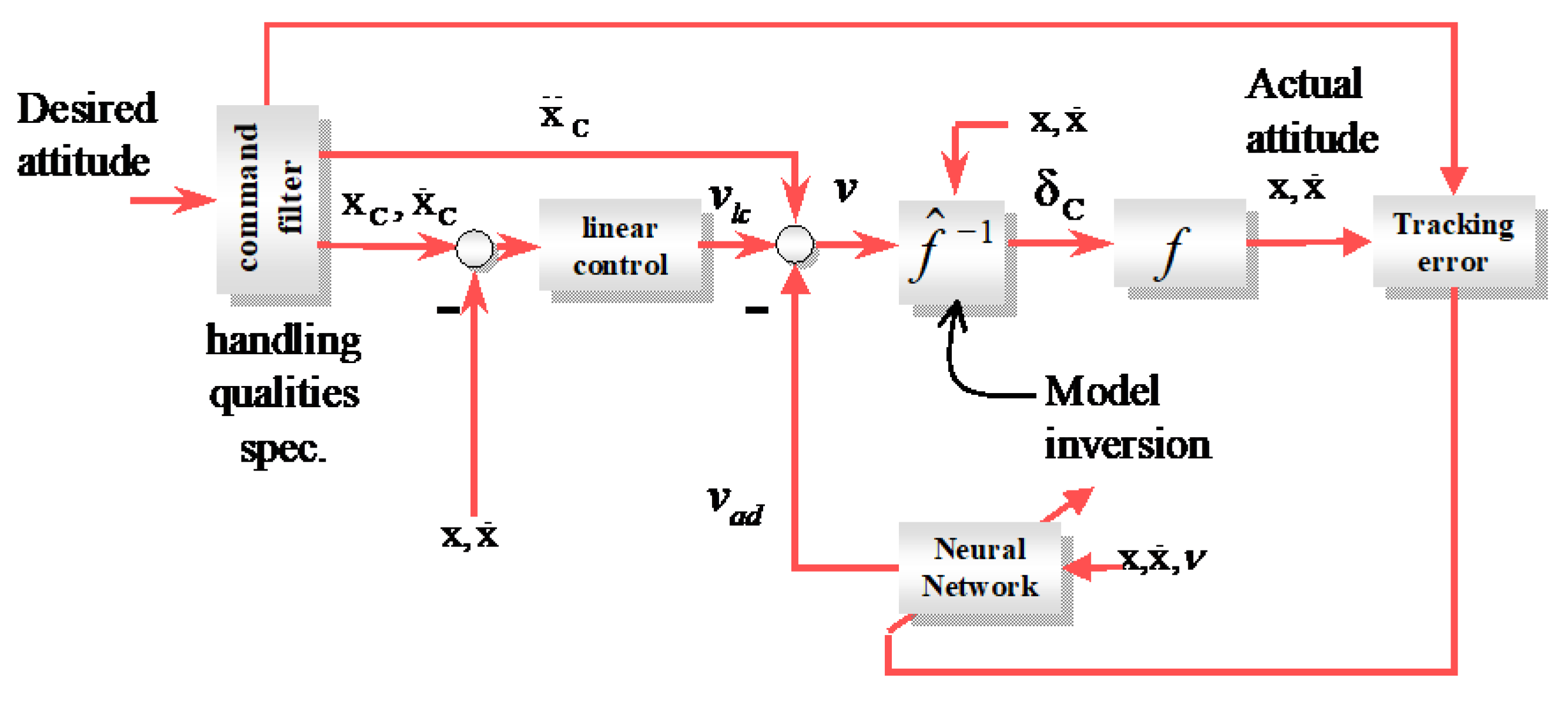
Here, we briefly summarize one application of our neural net (NN) controller. Our controller suite includes the nominal controller and the NN-based adaptive fault-tolerant controller. The nominal controller is used when the system is in a fault-free condition. The NN adaptive controller is activated after a fault is detected to compensate for the effect of the fault and to maintain acceptable control performance even in the presence of a fault. The fault-tolerant controller performance was demonstrated by using a well-known RCAM (Research Civil Aircraft Model) developed by the Group for Aeronautical Research and technology in Europe (GARTEUR). The design of the nominal controller is based on standard approximate dynamic inversion. Figure 9 illustrates the proposed nonlinear adaptive control architecture: the aircraft (f), the command filter to provide desired handling qualities, approximate dynamic inverse (), a conventional linear tracking controller as described above, and an online learning neural network to correct for errors and uncertainty in association with the inversion model.
One of the key advantages of the proposed fault-tolerant control scheme is its capability to handle any occurrences of new or unanticipated faults. The neural network-based adaptive controller activated after fault detection is still capable of compensating for the effect of the fault on-line and to maintain acceptable control performance before further pilot intervention.
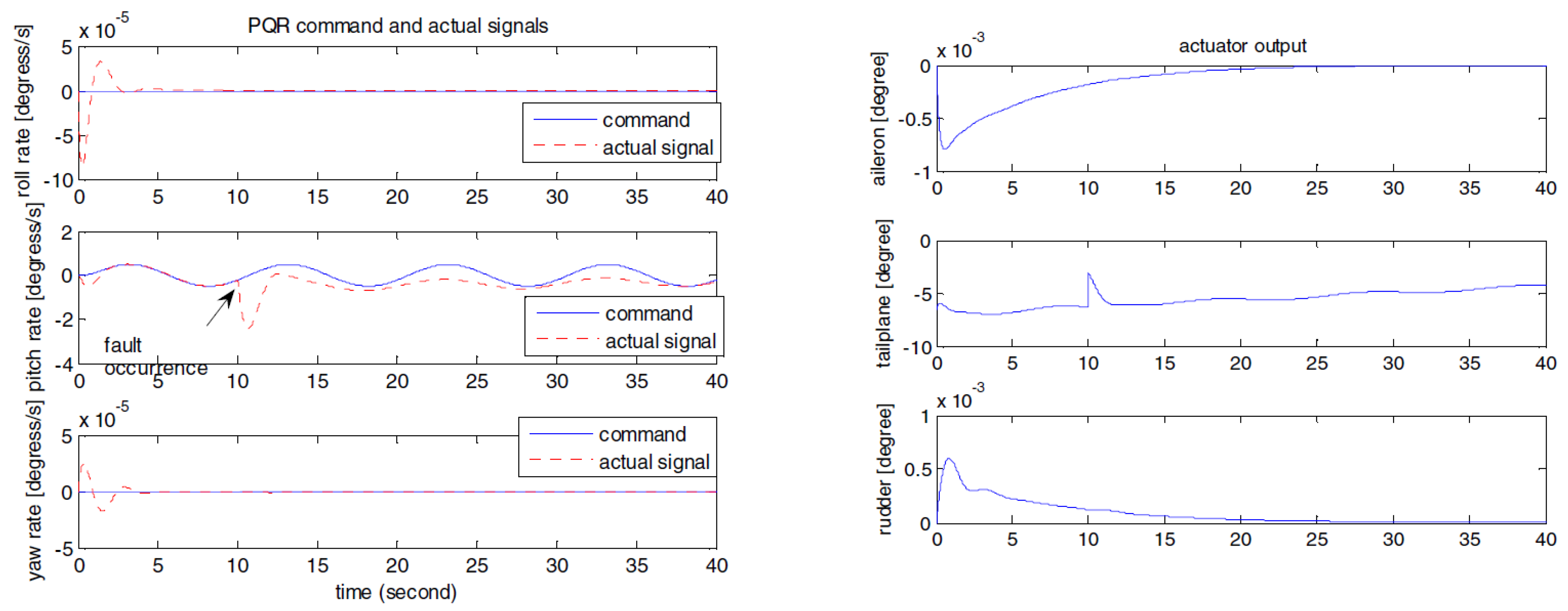
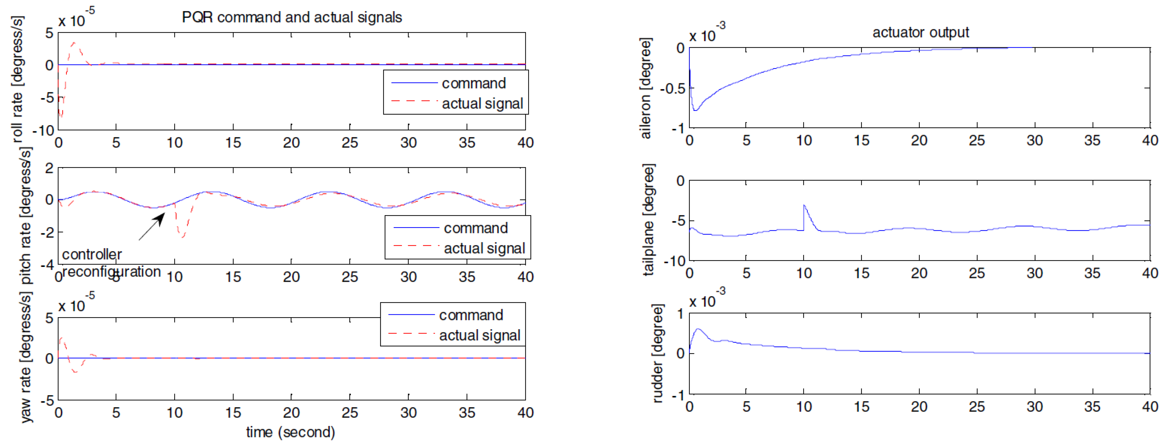
Figure 10 and Figure 11 give the control performances of the nominal controller and nonlinear adaptive controller engaged after a fault detection, respectively. We can clearly see the benefit of controller reconfiguration using on-line diagnostic information.
In recent years, there has been some new progress in fault-tolerant control. In [51], a hybrid fault-tolerant controller was proposed to handle control surface damages. Compared to the nonlinear control approach in [18], the controller in [51] was based on linearized models. In [52], a nonlinear sliding mode controller was proposed to deal with actuator failure in quadrotor UAVs. The inner loop was the attitude control and the outer loop was the position control. Sliding mode control was applied to both inner and outer loops. The control is challenging because if one or two control actuators fail, the system is under-actuated. A special form of sliding mode control was proposed based on back-stepping. In [53], an observed-based fault-tolerant controller was proposed for carrier-based UAVs. Some states in the UAVs are assumed to be unmeasurable and hence the control problem is challenging. The controller was nonlinear and closed-loop stability was given.
7. Contingency Planning
This is the last defense for fault mitigation in UAVs. The UAV has lost its engine and it is on its way to crash. Emergency landing via the parachute systems is part of the contingency planning for some small-to-medium sized UAVs [54]. However, for big and heavy drones like Global Hawk (12 tons) [55], parachute is not feasible. Can we still do something to minimize the damage? In other words, for fixed wing UAVs, the hanging time of some UAVs such as Global Hawk can still be 30 min or more due to its high flying altitude and large wing span. Moreover, if one plans ahead, the UAVs can still glide to some safe landing places such as airports, non-populated places such as beaches, waterways, grassy areas, etc. A well-known example is the US Airways Flight 1549, which avoided a crash landing by gliding onto the Hudson River.
In our recent papers [56,57,58,59,60], we have provided detailed procedures for contingency planning for engine failures.
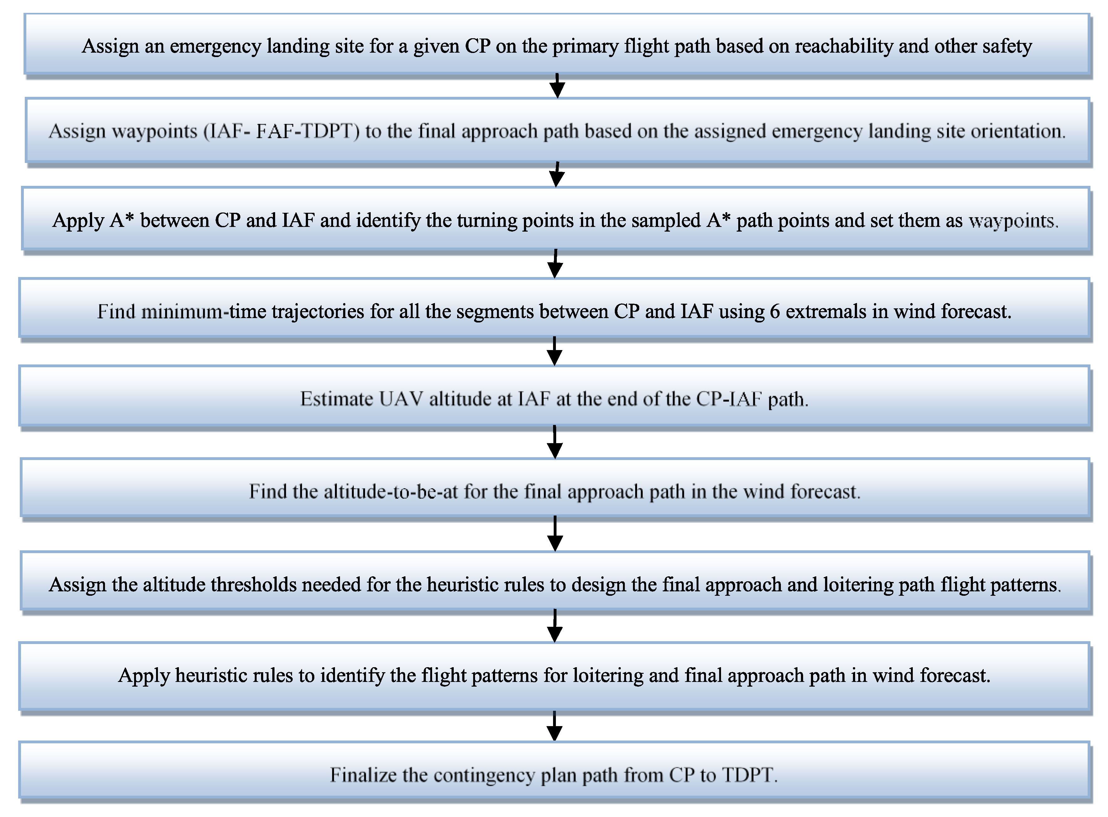
Figure 12 shows the workflow of contingency plan generation. It is an off-line process. Given a UAV and its associated flying capabilities (wingspan, gliding speed, descending rate, etc.) and also the theater of operations, we need the following two major steps: preprocessing and contingency plan generation. We will summarize those two steps in the next two sub-sections.
7.1. Preprocessing
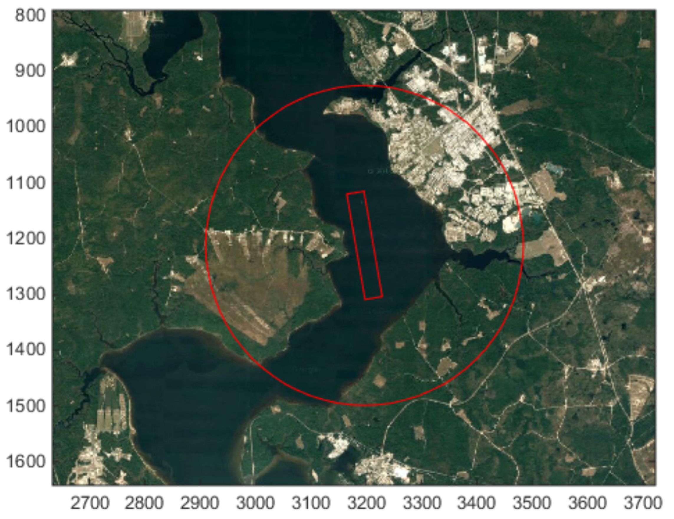
There are multiple modules in the preprocessing step. First, landing place selection is needed. Based on the UAV’s size and gliding speed, an appropriate landing site needs to have enough length. Potential landing sites include airport runways, beaches, waterways, etc. In [58], we developed a landing site selection algorithms based on Google maps. Figure 13 shows a landing site.
Second, for each landing site, we need to assign some waypoints such as Touchdown point (TDPT), Initial Approach Fix (IAF), and Final Approach Fix (FAF). Detailed procedures are provided in [56].
7.2. Contingency Plan Generation
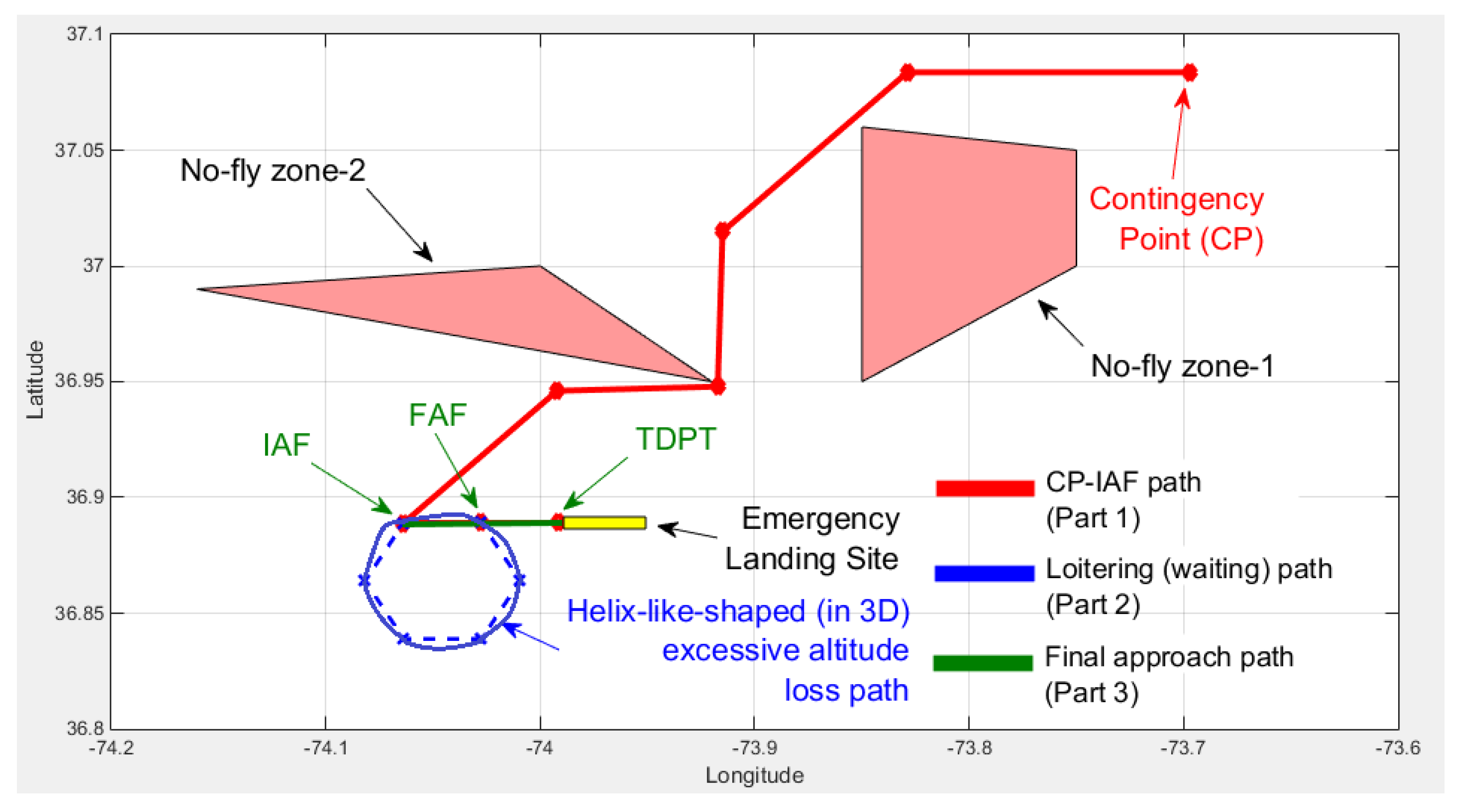
Given a primary flight plan containing hundreds or even thousands of waypoints, we need to generate a contingency plan for each waypoint. An example of a contingency plan is shown in Figure 14.
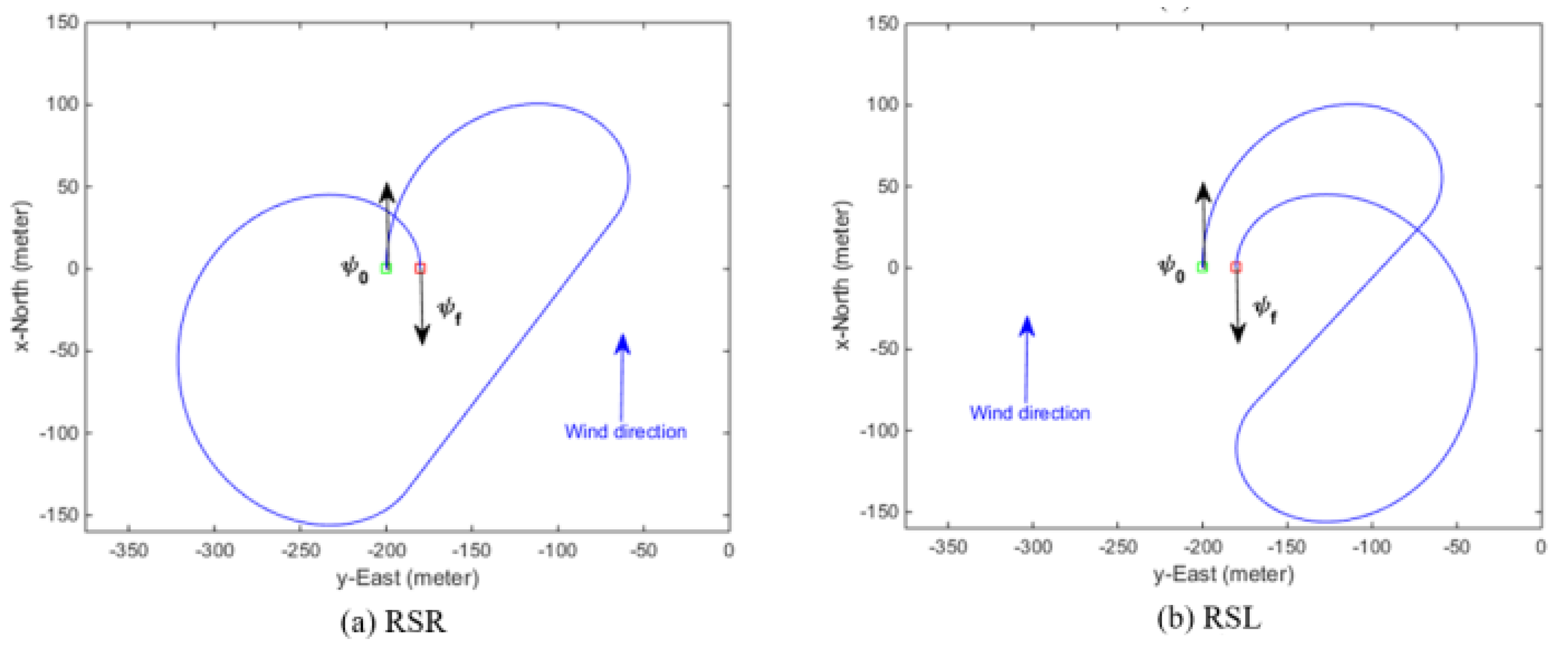
Suppose an engine failure occurs near a waypoint in the primary flight path, we will apply A* path planning algorithm [56] to generate a contingency path between the contingency point (CP) and the IAF. Some no-fly zones need to be bypassed. From Figure 14, the red line section shows the A* generated plan. In the contingency plan, when the UAV reaches the IAF, there may still be excessive altitude to lose. We have developed time-constrained path generation algorithm to lose excessive altitude [57]. Wind speed needs to be taken into account. Some extremal paths can be seen in Figure 15. RSR means right-straight-right; RSL means right-straight-left.
There are also some additional processing steps to deal with different excessive altitudes. Details can be found in [56].
One limitation of our contingency planning approach is that if the wind conditions deviate too much from the forecast conditions, which can happen in practice, then the pre-planned contingency paths may need to change on the fly. More research is needed in this direction.
7.3. Emergency Landing in Hudson River
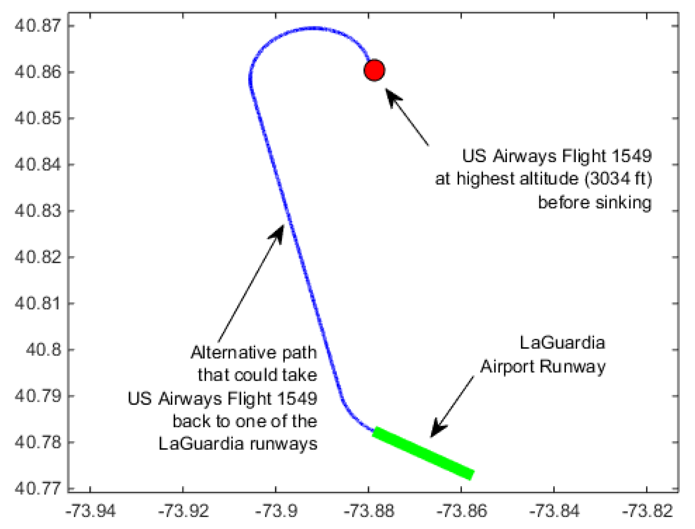
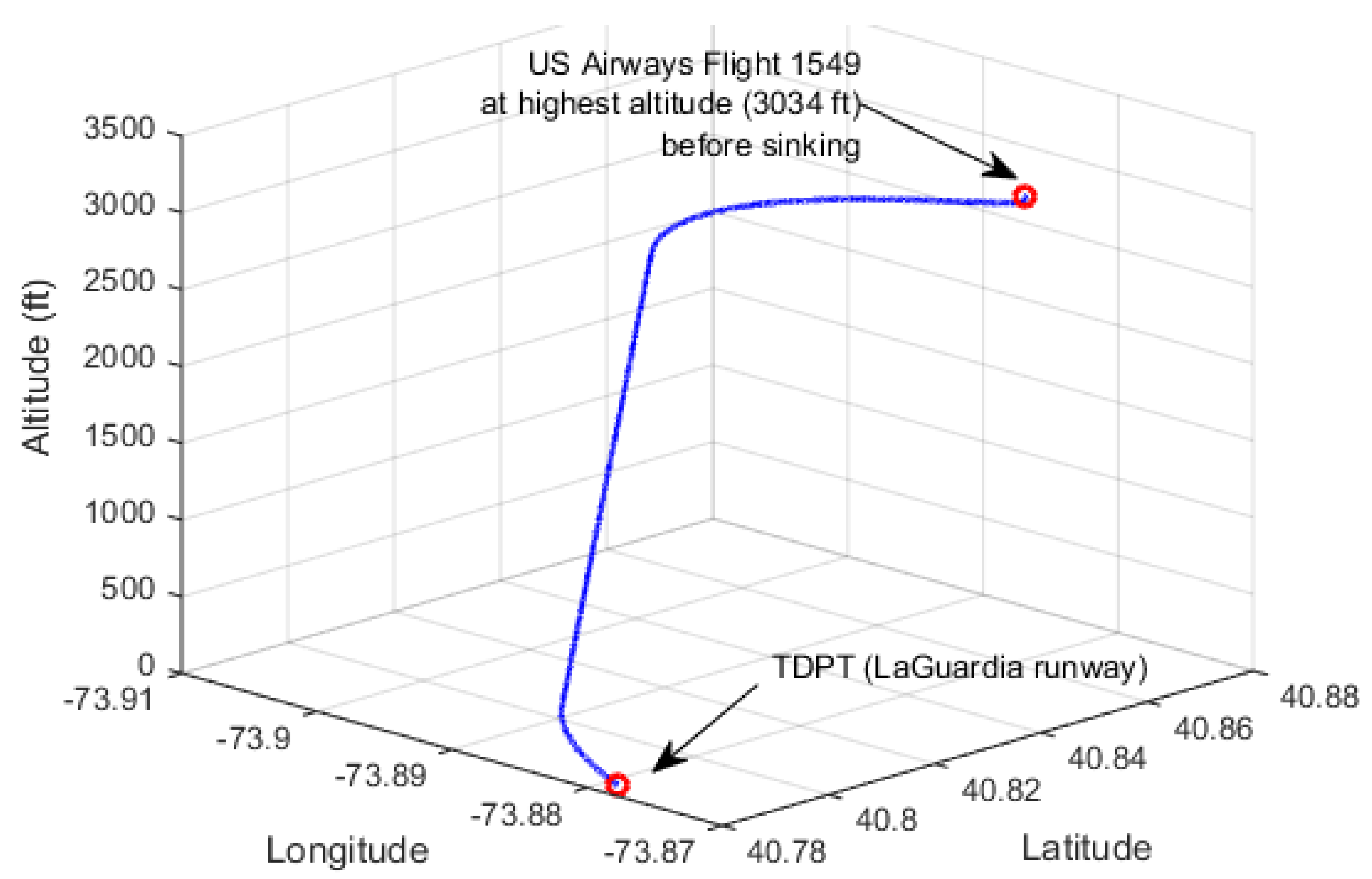
Here, we demonstrate how we generate a contingency plan for US Airways Flight 1549, which lost both engines due to a bird strike. The plane was on route from New York City’s LaGuardia Airport to Seattle, Washington and ditched into Hudson River on 15 January, 2009. In the climb phase right after its takeoff, it struck a flock of Canada geese and lost its engine power. The pilots Mr. Sullenberger and Mr. Skiles glided the plane to a ditching in the Hudson River. At the time of the bird strike, Flight 1549’s airspeed was about 200 knots. The highest altitude right before the plane started sinking was 3034 feet (925 m). At this altitude, the plane was located at coordinates: Latitude: 40.861666 degrees, Longitude: −73.879722 degrees. Time was 3:27:29 p.m. The wind amplitude was around 13.4 knots. The wind direction was 320 degrees. Assuming the coordinates at the highest altitude corresponds to the coordinates of CP, we found the heading angle at CP using the waypoint coordinates at the highest altitude, the waypoint right before that, and the wind information.
We applied our contingency plan generation tool to this incident. Figure 16 and Figure 17 show the top view and 3D view of the generated plan.
In the movie “Sully”, various flight simulator runs also showed that it was possible to return to LaGuardia and Teterboro airports. Why did the pilots choose to land on Hudson river? The reason is that the pilots need to follow some procedures to make sure both engines were lost. During this period of checking, the plane has lost quite some altitude. Consequently, there was not enough altitude to glide it back to the airports. Based on his experience, the pilot, Sullenberger, made some rough calculations and decided to land on Hudson Bay; the decision saved over 150 people onboard.
8. Conclusions
UAVs are gaining popularity. However, the safety of UAVs is not on par with manned aircraft. In this paper, we present safety enhancements of UAVs using signal processing algorithms, which can help condition-based maintenance, structural health monitoring, sensor and actuator fault diagnostics, fault magnitude reconstruction, fault-tolerant control, and contingency plan generation. Some recent advances in the aforementioned areas are also highlighted.
It is important to emphasize that UAV safety requires an integrated approach that contains all of the above. More research and development effort is needed to produce an integrated safety system for UAVs. For instance, the contingency plans are generated off-line, and if wind conditions deviate a lot from the forecast data during actual flights, our current system may not be able to handle that scenario. One potential future direction in contingency planning is to deal with highly dynamic windy conditions. Another direction is to devise some online contingency planning strategies to complement the off-line generated contingency plans.
Funding
This project was supported in part by US government under the PPP program. The views, opinions and/or findings expressed are those of the author(s) and should not be interpreted as representing the official views or the US Government.
Institutional Review Board Statement
Not applicable.
Informed Consent Statement
Not applicable.
Conflicts of Interest
The author declares no conflict of interest.
References
- Tvaryanas, A.P.; Thompson, B.T.; Constable, S.H. US military unmanned aerial vehicle mishaps: Assessment of the role of human factors using HFACS. In USAF 311th Performance Enhancement Directorate; Technical Report; HSW-PE-BR-TR-2005-0001; Brooks City-Base: San Antonio, TX, USA, 2005. [Google Scholar]
- Programs, Partnerships and Opportunities. US Department of Transportation, Federal Aviation Administration. Available online: https://www.faa.gov/uas/programs_partnerships (accessed on 23 February 2018).
- Kwan, C.; Ayhan, B. Enhancing Safety of UAVs in National Airspace. In Proceedings of the IEEE 9th Annual Computing and Communication Workshop and Conference, Las Vegas, NV, USA, 7–9 January 2019. [Google Scholar]
- Choi, C.; Lee, W. Design and evaluation of voltage measurement-based sectoral diagnosis method for inverter open switch faults of permanent magnet synchronous motor drives. IET Electr. Power Appl. 2012, 6, 526–532. [Google Scholar] [CrossRef]
- Kiani, M.; Lee, W.; Kenarangui, R.; Fahimi, B. Detection of Rotor Faults in Synchronous Generators. In Proceedings of the IEEE International Symposium on Diagnostics for Electric Machines, Power Electronics and Drives, Cracow, Poland, 6–8 September 2007; pp. 266–271. [Google Scholar]
- Zhang, G.; Kwan, C.; Xu, R.; Vichare, N.; Pecht, M. An Enhanced Prognostic Model for Intermittent Failures in Digital Electronics. In Proceedings of the IEEE Aerospace Conference, Big Sky, MT, USA, 3–10 March 2007; pp. 1–8. [Google Scholar]
- Zhao, X.; Qian, T.; Mei, G.; Kwan, C.; Zane, R.; Walsh, C.; Paing, T.; Popovic, Z. Active health monitoring of an aircraft wing with an embedded piezoelectric sensor/actuator network: II. Wireless approaches. J. Smart Mater. Struct. 2007, 16, 1218–1225. [Google Scholar] [CrossRef]
- Zhao, X.; Gao, H.; Zhang, G.; Ayhan, B.; Yan, F.; Kwan, C.; Rose, J.L. Active health monitoring of an aircraft wing with embedded piezoelectric sensor/actuator network: I. Defect detection, localization and growth monitoring. J. Smart Mater. Struct. 2007, 16, 1208–1217. [Google Scholar] [CrossRef]
- Kwan, C.; Xu, R. A note on simultaneous isolation of sensor and actuator faults. IEEE Trans. Control Syst. Technol. 2004, 12, 183–192. [Google Scholar] [CrossRef]
- Xu, R.; Kwan, C. Robust Isolation of Sensor Failures. Asian J. Control 2008, 5, 12–23. [Google Scholar] [CrossRef]
- Qin, S.J.; Li, W. Detection, identification, and reconstruction of faulty sensors with maximized sensitivity. AIChE J. 1999, 45, 1963–1976. [Google Scholar] [CrossRef]
- Dunia, R.; Qin, S.J. Joint diagnosis of process and sensor faults using principal component analysis. Control Eng. Pract. 1998, 6, 457–469. [Google Scholar] [CrossRef]
- Li, W.; Yue, H.; Valle-Cervantes, S.; Qin, S. Recursive PCA for adaptive process monitoring. J. Process Control 2000, 10, 471–486. [Google Scholar] [CrossRef]
- Lee, J.-M.; Qin, S.J.; Lee, I.-B. Fault detection and diagnosis based on modified independent component analysis. AIChE J. 2006, 52, 3501–3514. [Google Scholar] [CrossRef]
- Qin, S.J. Survey on data-driven industrial process monitoring and diagnosis. Annu. Rev. Control 2012, 36, 220–234. [Google Scholar] [CrossRef]
- Gertler, J.; Singer, D. Augmented Models for Statistical Fault Isolation in Complex Dynamic Systems. In Proceedings of the American Control Conference, Boston, MA, USA, 19–21 June 1985; pp. 317–322. [Google Scholar]
- Gertler, J.J. A numerical-structural approach to failure detection and isolation in complex plants. In Proceedings of the 1986 25th IEEE Conference on Decision and Control, Athens, Greece, 2 April 2007; pp. 1576–1580. [Google Scholar]
- Zhang, X.; Liu, Y.; Rysdyk, R.; Kwan, C.; Xu, R. An Intelligent Hierarchical Approach to Actuator Fault Diagnosis and Accommodation. In Proceedings of the 2006 IEEE Aerospace Conference, Big Sky, MT, USA, 4–11 March 2006. [Google Scholar]
- Kuljaca, O.; Swamy, N.; Lewis, F.; Kwan, C. Design and implementation of industrial neural network controller using backstepping. IEEE Trans. Ind. Electron. 2003, 50, 193–201. [Google Scholar] [CrossRef]
- Tao, G.; Kokotovic, P. Adaptive Control of Systems with Actuator and Sensor Nonlinearities; John Wiley & Sons: Hoboken, NJ, USA, 1996. [Google Scholar]
- Yeung, K.S.; Cheng, C.C.; Kwan, C. A Unifying Design of Classical and Sliding Controllers. IEEE Trans. Autom. Control 1993, 38, 1422–1426. [Google Scholar] [CrossRef]
- Ioannou, P.; Sun, J. Robust Adaptive Control; Dover Publications: Mineola, NY, USA, 2012. [Google Scholar]
- Kwan, C.; Xu, H.; Lewis, F.L. Robust Spacecraft Attitude Control Using Adaptive Fuzzy Logic. Int. J. Syst. Sci. 2000, 31, 1217–1225. [Google Scholar] [CrossRef]
- Ciuryla, M.; Liu, Y.; Farnsworth, J.; Kwan, C.; Amitay, M. Flight Control Using Synthetic Jets on a Cessna 182 Model. J. Aircr. 2007, 44, 642–653. [Google Scholar] [CrossRef]
- Zhao, D.; Polycarpou, M.M. Distributed Fault Accommodation for a Class of Interconnected Nonlinear Systems with Event-Triggered Inter-Communications. In Proceedings of the 2020 International Joint Conference on Neural Networks (IJCNN), Glasgow, UK, 19–24 July 2020. [Google Scholar]
- Zhang, K.; Jiang, B.; Yan, X.; Mao, Z.; Polycarpou, M.M. Fault-Tolerant Control for Systems with Unmatched Actuator Faults and Disturbances. In IEEE Transactions on Automatic Control; Early Access; IEEE: Piscataway, NJ, USA, 2020. [Google Scholar]
- Khalili, M.; Zhang, X.; Cao, Y.; Polycarpou, M.M.; Parisini, T. Distributed Fault-Tolerant Control of Multiagent Systems: An Adaptive Learning Approach. IEEE Trans. Neural Netw. Learn. Syst. 2020, 31, 420–432. [Google Scholar] [CrossRef] [Green Version]
- Keliris, C.; Polycarpou, M.M.; Parisini, T. An Adaptive Approach to Sensor Bias Fault Diagnosis and Accommodation for a Class of Input-Output Nonlinear Systems. In Proceedings of the IEEE Conference on Decision and Control (CDC), Miami Beach, FL, USA, 17–19 December 2018. [Google Scholar]
- Khalili, M.; Zhang, X.; Cao, Y.; Polycarpou, M.M.; Parisini, T. Distributed adaptive fault-tolerant leader-following formation control of nonlinear uncertain second-order multi-agent systems. Int. J. Robust Nonlinear Control 2018, 28, 4287–4308. [Google Scholar] [CrossRef]
- Zhang, X.; Xu, R.; Kwan, C.; Haynes, L.; Yang, Y.; Polycarpou, M. Fault tolerant formation flight control of UAVs. Int. J. Veh. Auton. Syst. 2004, 2, 217. [Google Scholar] [CrossRef]
- Polycarpou, M.; Zhang, X.; Xu, R.; Yang, Y.; Kwan, C. A Neural Network Based Approach to Adaptive Fault Tolerant Flight Control. In Proceedings of the 2004 IEEE International Symposium on Intelligent Control, Taipei, Taiwan, 4 September 2004; pp. 61–66. [Google Scholar]
- Coombes, M.; Chen, W.H.; Render, P. Reachability Analysis of Landing Sites for Forced Landing of a UAS in Wind Using Trochoidal Turn Paths. In Proceedings of the International Conference on Unmanned Aircraft Systems, Piscataway, NJ, USA, 9–12 June 2015; pp. 62–71. [Google Scholar]
- Wongsaichua, W.; Lee, W.; Oraintara, S.; Kwan, C.; Zhang, F. Integrated high speed intelligent utility tie unit for disbursed/renewable generation facilities. IEEE Trans. Ind. Appl. 2005, 41, 507–513. [Google Scholar] [CrossRef]
- Jain, H.; Korkua, S.; Lee, W.J.; Kwan, C. Detection and Severity Classification of Rotor Imbalance Faults in Induction Machines. In Proceedings of the IEEE-IAS Annual Conference, Houston, TX, USA, 3–7 October 2010. [Google Scholar]
- Higgs, P.A.; Parkin, R.; Jackson, M.; Al-Habaibeh, A.; Zorriassatine, F.; Coy, J. A Survey on Condition Monitoring Systems in Industry. In Proceedings of the ASME 7th Biennial Conference on Engineering Systems Design and Analysis, Manchester, UK, 19–22 July 2004; Volume 3, pp. 163–178. [Google Scholar]
- Mohammed, A.; Norman, E.S.; Abouel, N.; Adel, A.S.; Husam, K. Overview of predictive condition based maintenance research using bibliometric indicators. J. King Saud Univ. Eng. Sci. 2019, 31, 355–367. [Google Scholar]
- Korkua, S.K.; Lee, W.-J.; Kwan, C. Design and Implementation of Zigbee based Vibration Monitoring and Analysis for Electrical Machines. In Proceedings of the International Conference on Wireless Networks—ICWN’11, Las Vegas, NV, USA, 18–21 July 2011. [Google Scholar]
- Korkua, S.; Jain, H.; Lee, W.-J.; Kwan, C. Wireless Health Monitoring System for Vibration Detection of Induction Motors. In Proceedings of the IEEE-IAS, ICPS Annual Conference, Tallahassee, FL, USA, 9–13 May 2010. [Google Scholar]
- Lai, C.T.A.; Jiang, W.; Jackson, P.R. Internet of Things enabling condition-based maintenance in elevators service. J. Qual. Maint. Eng. 2019, 25, 563–588. [Google Scholar] [CrossRef]
- Kwan, C.; Huang, H.; Islam, M.M.; Ayhan, B. Unpowered Wireless Ultrasound Generation and Sensing for Structural Health Monitoring of Composites. In Proceedings of the IEEE International Conference on Prognostics and Health Management, Seattle, WA, USA, 11–13 June 2018. [Google Scholar]
- Xu, R.; Zhang, G.; Zhang, X.; Kwan, C.; Semega, K. Sensor Validation Using Nonlinear Minor Component Analysis. In Proceedings of the Third International Symposium on Neural Networks, Lecture Notes in Computer Science, Chengdu, China, 28 May–1 June 2006. [Google Scholar]
- Zhang, X.; Polycarpou, M.M.; Xu, R.; Kwan, C. Actuator Fault Diagnosis and Accommodation for Improved Flight Safety. In Proceedings of the IEEE International Symposium on Intelligent Control and Mediterranean Conference on Control and Automation Conference, Limassol, Cyprus, 27–29 June 2005; pp. 640–645. [Google Scholar]
- Dunia, R.; Qin, J.; Edgar, T.F.; McAvoy, T.J. Identification of faulty sensors using principal component analysis. AIChE J. 1996, 42, 2797–2812. [Google Scholar] [CrossRef]
- Deluca, A.; Mattone, R. Actuator Failure Detection and Isolation Using Generalized Momenta. In Proceedings of the IEEE Conference on Robotics and Automation, Taipei, Taiwan, 14–19 September 2003; pp. 634–639. [Google Scholar]
- Frank, P. Fault diagnosis in dynamic systems using analytical and knowledge-based redundancy: A survey and some new results. Automatica 1990, 26, 459–474. [Google Scholar] [CrossRef]
- Yi, J.; Huang, D.; He, H.; Zhou, W.; Han, Q.; Li, T. A Novel Framework for Fault Diagnosis Using Kernel Partial Least Squares Based on an Optimal Preference Matrix. IEEE Trans. Ind. Electron. 2017, 64, 4315–4324. [Google Scholar] [CrossRef]
- Yi, J.; Wu, L.; Zhou, W.; He, H.; Yao, L. A Sparse Dimensionality Reduction Approach Based on False Nearest Neighbors for Nonlinear Fault Detection. IEEE Trans. Syst. Man Cybern. Syst. 2019, 1–13. [Google Scholar] [CrossRef]
- Li, W.; Kwan, C. A Novel Approach to Sensor and Actuator Integrity Monitoring. In Proceedings of the IEEE Conference on Decision and Control, Las Vegas, NV, USA, 12–14 December 2016; pp. 2140–2145. [Google Scholar]
- Ando, T.; Kugimiya, W.; Hashimoto, T.; Momiyama, F.; Aoki, K.; Nakano, K. Lateral Control in Precision Docking Using RTK-GNSS/INS and LiDAR for Localization. IEEE Trans. Intell. Veh. 2020. [Google Scholar] [CrossRef]
- ADS-B. Available online: https://www.faa.gov/nextgen/programs/adsb/faq/ (accessed on 13 February 2021).
- Ergöçmen, B.; Yavrucuk, İ. Active Hybrid Fault Tolerant Flight Control of an UAV under Control Surface Damage. In Proceedings of the American Control Conference (ACC), Denver, CO, USA, 1–3 July 2020; pp. 4169–4174. [Google Scholar]
- Zhu, Z.; Cao, S. Back-stepping sliding mode control method for quadrotor UAV with actuator failure. J. Eng. 2019, 2019, 8374–8377. [Google Scholar] [CrossRef]
- Zheng, F.; Zhen, Z.; Gong, H. Observer-based backstepping longitudinal control for carrier-based UAV with actuator faults. J. Syst. Eng. Electron. 2017, 28, 322–337. [Google Scholar]
- Al-Madani, B.; Svirskis, M.; Narvydas, G.; Maskeliūnas, R.; Damaševičius, R. Design of Fully Automatic Drone Parachute System with Temperature Compensation Mechanism for Civilian and Military Applications. J. Adv. Transp. 2018, 2018, 1–11. [Google Scholar] [CrossRef]
- Global Hawk. Available online: https://www.reuters.com/article/us-mideast-iran-usa-factbox/factbox-the-global-hawk-drone-shot-down-by-iran-idUSKCN1TL29K (accessed on 13 February 2021).
- Ayhan, B.; Kwan, C.; Budavari, B.; Larkin, J.; Gribben, D. A Preflight Contingency Planning Approach for Fixed Wing UAVs in Full Loss of Thrust Using Wind Forecast. Sensors 2018, 19, 227. [Google Scholar] [CrossRef] [Green Version]
- Ayhan, B.; Kwan, C. Time-Constrained Extremal Trajectory Design for Fixed-Wing Unmanned Aerial Vehicles in Steady Wind. J. Guid. Control Dyn. 2018, 41, 1569–1576. [Google Scholar] [CrossRef]
- Ayhan, B.; Kwan, C.; Um, Y.-B.; Budavari, B.; Larkin, J. Semi-Automated Emergency Landing Site Selection Approach for UAVs. IEEE Trans. Aerosp. Electron. Syst. 2019, 55, 1892–1906. [Google Scholar] [CrossRef]
- Ayhan, B.; Kwan, C.; Budavari, B.; Larkin, J.; Gribben, D. Path Planning for UAVs with Engine Failure in the Presence of Winds. In Proceedings of the Industrial Electronics Society, IECON 2018-44th Annual Conference of the IEEE, Washington, DC, USA, 21–23 October 2018. [Google Scholar]
- Ayhan, B.; Kwan, C. A Comparative Study of Two Approaches for UAV Emergency Landing Site Surface Type Estimation. In Proceedings of the Industrial Electronics Society, IECON 2018-44th Annual Conference of the IEEE, Washington, DC, USA, 21–23 October 2018. [Google Scholar]
Figure 1.
Enhancing UAV safety from the perspectives of signal processing algorithms.

Figure 2.
The use WSN for induction motor monitoring.

Figure 3.
Schematic view of the direct analog RF coupling approach for wireless aircraft wing inspection.
Figure 3.
Schematic view of the direct analog RF coupling approach for wireless aircraft wing inspection.

Figure 4.
Application of ultrasonic sensor/actuator array to monitor aircraft wing panel.

Figure 5.
Recent SHM using wireless sensors for active crack detection.

Figure 6.
Comparison of results with fault tolerance and without fault tolerance. (a) Without fault tolerance (one UAV is drifting away); (b) with fault tolerance.
Figure 6.
Comparison of results with fault tolerance and without fault tolerance. (a) Without fault tolerance (one UAV is drifting away); (b) with fault tolerance.

Figure 7.
Various actuators in a hypothetical aircraft.

Figure 8.
Illustration of fault-tolerant control strategy.

Figure 9.
Neural Network Augmented Model Inversion Control Architecture.

Figure 10.
Tracking performance of the nominal controller when a aileron failure occurs at t = 10 s.
Figure 10.
Tracking performance of the nominal controller when a aileron failure occurs at t = 10 s.

Figure 11.
Tracking performance with controller reconfiguration after detection of a tailplane failure.
Figure 11.
Tracking performance with controller reconfiguration after detection of a tailplane failure.

Figure 12.
Contingency plan generation workflow [56].
Figure 12.
Contingency plan generation workflow [56].

Figure 13.
Landing site candidate-1 (green dotted line passes through the center of the landing site along its length).
Figure 13.
Landing site candidate-1 (green dotted line passes through the center of the landing site along its length).

Figure 14.
Contingency plan example.

Figure 15.
Two extremal paths. Other paths such as LSR, LSL, RSL, and RSR can be found in [57].
Figure 15.
Two extremal paths. Other paths such as LSR, LSL, RSL, and RSR can be found in [57].

Figure 16.
Contingency plan for US Airways Flight 1549 to return to LaGuardia airport: Top down view.
Figure 16.
Contingency plan for US Airways Flight 1549 to return to LaGuardia airport: Top down view.

Figure 17.
Contingency plan for US Airways Flight 1549 to return to LaGuardia airport: 3D view.


Table 1.
Primary, secondary and tertiary actuators for the roll, pitch, and yaw channels.
| Primary Actuator | Secondary Actuator | Tertiary Actuator | |
|---|---|---|---|
| Roll Channel | Aileron | Rudder & Asymmetric Engine Thrust | N/A |
| Pitch Channel | Tailplane | Symmetric Aileron | Symmetric Engine Thrust |
| Yaw Channel | Rudder | Asymmetric Engine |
Publisher’s Note: MDPI stays neutral with regard to jurisdictional claims in published maps and institutional affiliations. |
© 2021 by the author. Licensee MDPI, Basel, Switzerland. This article is an open access article distributed under the terms and conditions of the Creative Commons Attribution (CC BY) license (http://creativecommons.org/licenses/by/4.0/).
Share and Cite
MDPI and ACS Style
Kwan, C. Safety Enhancement of UAVs from the Signal Processing’s Perspectives: A Bird’s Eye View. Drones 2021, 5, 16. https://0-doi-org.brum.beds.ac.uk/10.3390/drones5010016
AMA Style
Kwan C. Safety Enhancement of UAVs from the Signal Processing’s Perspectives: A Bird’s Eye View. Drones. 2021; 5(1):16. https://0-doi-org.brum.beds.ac.uk/10.3390/drones5010016
Chicago/Turabian StyleKwan, Chiman. 2021. "Safety Enhancement of UAVs from the Signal Processing’s Perspectives: A Bird’s Eye View" Drones 5, no. 1: 16. https://0-doi-org.brum.beds.ac.uk/10.3390/drones5010016