
A Multilevel Architecture for Autonomous UAVs


Department of Information Engineering, University of Florence, Via Santa Marta 3, 50139 Firenze, Italy
*
Author to whom correspondence should be addressed.
Drones 2021, 5(3), 55; https://0-doi-org.brum.beds.ac.uk/10.3390/drones5030055
Submission received: 14 May 2021
/
Revised: 25 June 2021
/
Accepted: 28 June 2021
/
Published: 30 June 2021
(This article belongs to the Special Issue Feature Papers of Drones)
Abstract
:In this paper, a multilevel architecture able to interface an on-board computer with a generic UAV flight controller and its radio receiver is proposed. The computer board exploits the same standard communication protocol of UAV flight controllers and can easily access additional data, such as: (i) inertial sensor measurements coming from a multi-sensor board; (ii) global navigation satellite system (GNSS) coordinates; (iii) streaming video from one or more cameras; and (iv) operator commands from the remote control. In specific operating scenarios, the proposed platform is able to act as a “cyber pilot” which replaces the role of a human UAV operator, thus simplifying the development of complex tasks such as those based on computer vision and artificial intelligence (AI) algorithms which are typically employed in autonomous flight operations.
1. Introduction
In the scientific community, one of the topics of major interest in the UAV field concerns autonomous navigation based on computer vision [1,2]. Many authors have proposed motion capture systems (mocap) [3,4,5,6,7,8], as they guarantee the highest performance. Given the high precision that these systems are able to achieve, they are often used to compare different control techniques. This approach allows for appreciating even small differences in the performance of different control algorithms.
However, the progress made in terms of research development regarding mocap systems is not reflected in the industrial sector, since most of the navigation algorithms and control techniques that exploit mocap technology (which is ground assisted) can hardly be extensively implemented on the typical environments of this field. Recently, thanks to the technological evolution and the proliferation of open source boards such as Raspberry Pi and Nvidia Jetson (running operating systems such as Linux), the research community has become increasingly interested in on-board vision-based navigation (VBN) techniques [9,10,11,12]. Given the possibilities currently offered by technology and the large amount of novel applications which can be envisioned in this new setting, the interest has shifted to how to solve the problem of the autonomous navigation of UAVs without ground assistance.
In order to investigate this new formulation of the problem, the classic UAV architecture shown in Figure 1 and composed of a micro-controller, sensors and a receiver capable of establishing a radio link for the drone commands is no longer sufficient. Instead, it is necessary to use a multilevel architecture, composed of both classic micro-controllers and other boards capable of processing images and complex algorithms, where each level must be able to communicate with the adjacent ones (see, e.g., [4]). As a consequence, the complexity of the drone inevitably increases.
In the multilevel paradigm, the choice of hardware is crucial, because this affects the internal communications, and this is particularly true for what concerns the flight controller device. A quite popular choice for the flight controller board in UAV robotic applications is PixHawk. In fact, most of the scientific papers dealing with the development of technology and algorithms for autonomous UAVs use this platform [13]. Among the most important reasons for this choice, two are prominent: (i) the PixHawk board was one of the first and most complete open source platforms for drones; and (ii) some custom versions of the firmware give native support for a robot operating system (ROS), a popular framework for robot development and programming [4]. Indeed, usually on UAVs based on a multilevel hardware, an additional card running ROS is used. This latter can be regarded as a “high-level” device, specifically designed for solving the original robotic problem, and that must communicate with the “lower” flight controller in order to perform the correct action. PixHawk platforms are able to receive ROS commands through a UART port, which uses the MAVLINK protocol [14,15,16]. Despite its popularity, this approach has some limitations, since the choice of flight controller is limited to PixHawk, which can only be driven via the MAVLINK protocol.
The approach presented in this paper, on the other hand, is conceived to increase flexibility in the choice of the hardware configuration, and thus, to avoid these limitations. Such a feature is obtained by implementing proper inter-level interfaces according to the decode–elaborate–encode paradigm, which allows, for instance, the regeneration of the signals sent to the flight controller, using any protocol used by commercially available receivers. Thanks to this feature, any flight controller can be used without the need to adapt to the hardware configuration of the software implementing the solution of the robotic problem.
This paper is organized as follows: Section 2 describes the general UAV multilevel architecture and the interfaces among the different layers, introducing the concept of a cyber pilot for autonomous navigation. Moreover, considerations of the mechanical design of the UAV with respect to the additional sensors and boards required are also presented, along with actual hardware/software implementation. Section 3 shows the experimental results of a specific autonomous mission performed by the UAV in an indoor environment using vision-based navigation. Finally, Section 4 reports concluding remarks and future developments.
2. Materials and Methods
2.1. Architecture
The proposed architecture aims to provide a flexible hardware and software platform for UAV robotic applications. The basic idea is in the subdivision of the general problem into sub-problems, which can be directly related to hardware or software implementations. Each solution is placed into a “level” comprising affine elements, and the levels are then interconnected to each other by standardized interfaces. Therefore, regarding UAV robotic applications based on VBN techniques, an architecture comprising three different abstract levels has been envisioned. The functions each single level is devoted to are listed below, and because of the hierarchical division of the problem, they are assumed to only communicate with adjacent levels.
- Functional high-level.This comprises the hardware and software necessary to implement the VBN system and to run the autonomous navigation algorithms.
- Functional mid-level.This is represented by the software necessary to manage the commands sent to the flight controller, which can be those from the ground station (human pilot remote control) or the ones generated by the autonomous navigation algorithm. This is the communication interface between the other two levels of the architecture.
- Functional low-level.It comprises the flight controller together with the hardware and software necessary for the attitude stabilization of the drone.
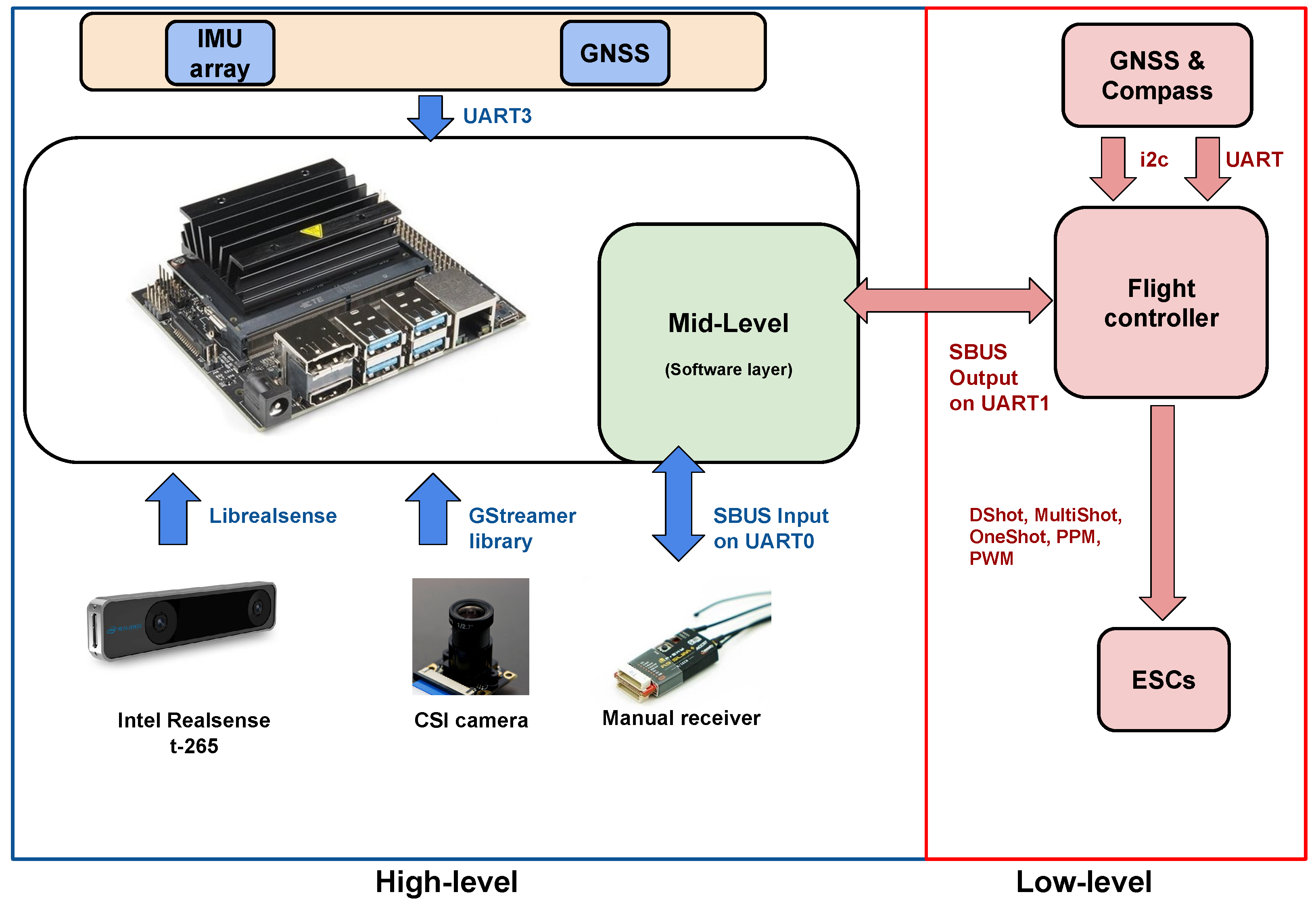
In Figure 2, a more detailed description of the used implementation of this architecture is reported. The low-level is mainly implemented as a hardware layer. Indeed, it accounts for a generic flight controller for drones and its equipped software, as well as the devices (i.e., sensors) necessary for attitude stabilization. Conversely, the mid-level is implemented as a software layer, which, in the presented solution, is hosted in the same Jetson Nano board used for the high-level. Indeed, this latter comprises both the hardware and software needed to implement the autonomous navigation system, that is, the previous Jetson Nano board and the related devices illustrated in Figure 2. In detail, the Jetson Nano is equipped with the following sensors:
- A multi-sensor board, also comprising a GNSS receiver, connected through a UART3 port;
- An Intel Realsense t-265, connected via USB-3.0 and used for the 3D localization and orientation of the drone;
- A digital camera, connected via Camera Serial Interface (CSI) and used by computer vision algorithms.
The multi-sensor unit was designed to collect position and inertial data from a multitude of different sensors. The board hosts two U-Blox NEO-M9N precision GNSS receivers, which provide an absolute position at the 18 Hz rate in a dual-redundant configuration. Roll, pitch and yaw angles and altitude values are estimated by means of micro electro mechanical systems-based (MEMS) 3D inertial sensors (accelerometer and gyroscope), a 3D magnetometer and an MEMS barometric pressure sensor. All the sensors are proposed in a triple-redundant configuration. Finally, a micro-controller unit (STM32L476) collects the digital samples from all the sensors and performs a sensor fusion algorithm [17,18] to provide a stable and reliable estimation of the roll, pitch and yaw angles at a rate of 200 Hz.
It is worth noting that, in this architecture implementation, the low-level is just an attitude controller equivalent to the ones used in traditional UAV configurations. As such, it accounts for a fully equipped flight controller, and indeed, it has its own sensors (e.g., a compass and a GNSS receiver) as shown in Figure 2, and it can execute the functions this kind of system is usually able to run (e.g., the return to home (RTH).
As it will be detailed in Section 2.2, the software layer representing the mid-level has the important role of deciding which command has to be sent to the flight controller between the one received from the receiver and the signal generated by the high-level. The actual signal passed to the flight controller depends in general on the policies of the mid-level, and possibly on the commands from the human pilot
2.2. Mid-Level Software Layer: Cyber Pilot and Interface with the Low-Level Implementation
As introduced in Section 2.1, the proposed architecture was conceived so that the high- and mid-level software implementations are such that any signal from the drone receiver passes through the Jetson Nano before arriving to the flight controller (see also [9,19]). This intermediate stage of processing allows for substituting the commands from the receiver with others generated by the high-level software running on the same Jetson Nano, thus replacing the human pilot with a “cyber pilot” (see also [19]). According to such a concept, the problem of driving the drone motion is “lifted” to the same sphere of the human operator, whereas the common approach, instead, “pulls down” the control strategy to the motor sphere. On the one hand, the disadvantages are that the controller is bound to act as a human, but on the other hand, the problems of elaborating the control strategy and of driving the motors are held separated, and so they can be solved and implemented as different modules.
The cyber pilot paradigm makes the system independent on the low-level implementation, as long as this latter uses standard interfaces. Indeed, as already noted, from the functional point of view, the low-level can be implemented by a traditional, fully equipped flight controller. Therefore, it is not necessary to design a custom implementation of this level, and already existing solutions can be used. The mid-level software layer manages this interface, and therefore, any flight controller can be used, provided that it can be physically interconnected to the high-level hardware layer (where the mid-level software runs), and its communication protocol is known.
In the implementation of the proposed architecture, the low-level is represented by a system based on a CC3D Revo flight controller running the LibrePilot firmware. This controller provides good performance (it has been specifically developed for racing applications) and it respects the form factor of the chosen drone frame. Moreover, it communicates using standard connectors and protocols. It is worth pointing out that the flight controller has been configured to operate in the “stabilize” mode, which only provides attitude control, leaving the altitude to be controlled manually. Therefore, the cyber pilot must be implemented to control the altitude as well.
Depending on the mid-level software layer policies, a variety of behaviors can be implemented. For instance, the autonomous flight mode can be switched back to the manual flight mode at any time with a simple strategy based on auxiliary channels in the communication with the human pilot. Indeed, the software layer implementing the mid-level can read all the channels transmitted by the ground station, and therefore, one of them can be used to carry auxiliary information specifically directed to the define the switching policy. Hence, depending on this input, the software can decide whether to replace the human commands read on the Jetson UART0 port (input) with others generated by the cyber pilot, or to transfer them to the UART1 port (output) directed to the flight controller.
The advantages of the cyber pilot approach are evident when the possible protocols for the communication between the receiver and the flight controller are taken into account. In the typical solutions, receiver and flight controller must share the communicating protocol, whereas the cyber pilot approach, introducing a signal processing stage in between the two devices, is not affected by this limitation.
On the mass market, drone receivers use three main communication protocols to send the operator commands to the flight controller:
- Pulse width modulation (PWM);
- Pulse position modulation (PPM);
- Serial bus (SBUS),
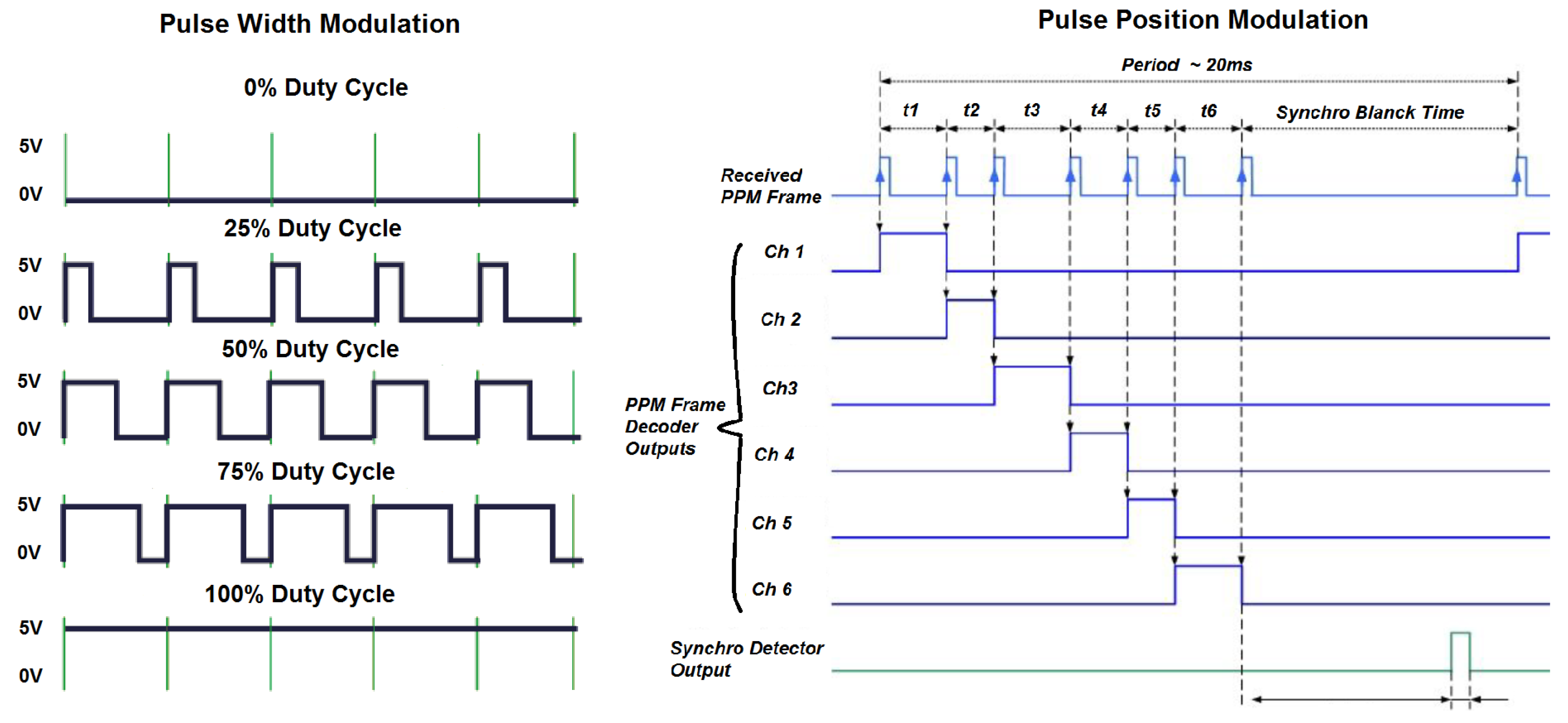
The PWM protocol is the oldest among them and as illustrated in Figure 3, it is based on the variation of a duty cycle. The signal from a radio channel is passed through a single wire, i.e., if one needs to transmit 8 channels to the flight controller (for example, 4 channels to control the drone and 4 to transmit additional information), it is necessary to connect 8 wires between the receiver and the flight controller.
The PPM protocol was introduced just to reduce the wiring needed to send the channels to the flight controller. As shown in Figure 3, this protocol modulates all the channels on a single wire. It is an analog protocol, just like PWM, and it is able to transmit multiple channels on a single wire under a bandwidth limitation, which is about 44 Hz for the transmission of eight channels.
The implementation presented in this paper exploits the SBUS protocol, since it has the following advantages over the previously mentioned ones: (i) it is the most recent protocol and represents today’s state of the art for drone receivers; (ii) it is a digital protocol, so it is not affected by noise; and (iii) this standard allows for transmitting up to 16 channels with a band equal to 100 Hz. Furthermore, it is worth noting that it is also the only protocol which can be easily read and regenerated by the Jetson Nano board. Indeed, doing the same with analog protocols (PWM and PPM) would require to manage interrupts in real time, that cannot be accurately achieved on cards not running real-time operating systems—such as the Jetson Nano.
As illustrated in Figure 4, an SBUS frame is made up of 25 bytes, where Byte 0 represents the header, bytes from 1 to 22 contain the information relating to the 16 channels to be transmitted, Byte 23 contains some additional information (not always used) and the fail-safe management in case the receiver is unable to receive commands from the ground station. Finally, Byte 24 is the closing byte of the frame.
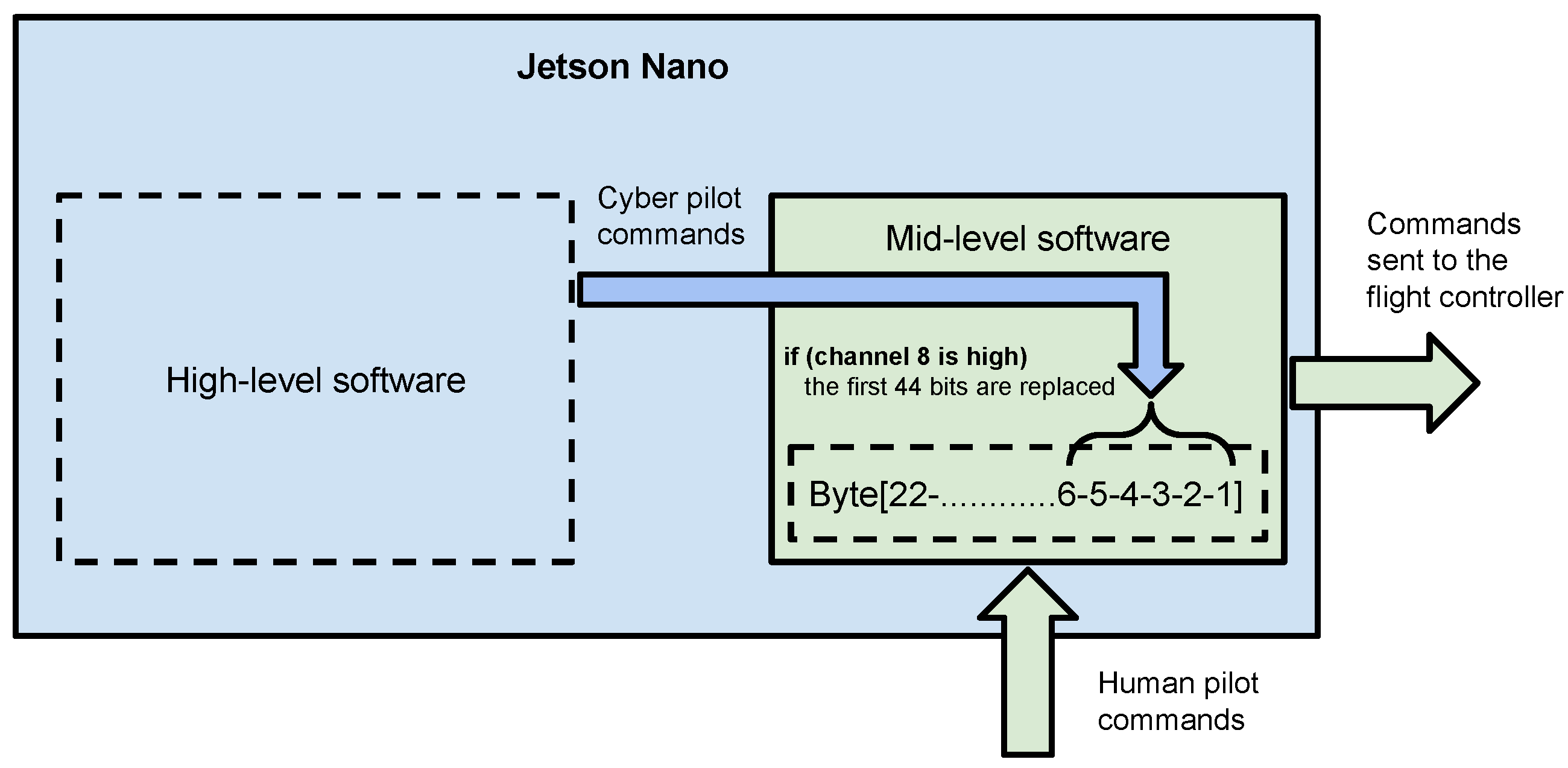
Since a single channel was coded with 11 bits, the SBUS standard can associate a maximum of 2048 different values to each channel. This defines the maximum resolution obtainable with this protocol. In the mid-level of the proposed architecture, a software for decoding the SBUS frames coming from the drone receiver was implemented along with another software for (re-)coding the information to be sent to the flight controller. In the current implementation of the mid-level, the human operator commands were overwritten by those generated by the cyber pilot, when a high signal is read in channel 8 of the SBUS frame. This command was sent by the ground station, and when it was received and read by the mid-level, this latter replaces the first 44 bits contained in the byte range relating to the status of the channels. Indeed, these first 44 bits of the SBUS sub-frame contain the commands associated with the reference values for pitch, roll, yaw and thrust. This way, the cyber pilot takes the command of the drone bypassing the human pilot, who can still resume manual control at any time by sending a low signal in the same channel 8. If required, it would also be possible to program the mid-level to replace all 16 channels. This could be useful for sending additional commands to the flight controller during the autonomous flight modes managed by the cyber pilot. Figure 5 shows a principle diagram of the mid-level where its operation can be considered as a software switch, capable of assigning the drone commands to the cyber pilot or to the human one at will.
2.3. High-Level Software Layer
In this section, we illustrate the overall structure and operating logic of the software layer pertaining to the high-level.
From the functional point of view, this layer implements all the software necessary for the cyber pilot, i.e., for the autonomous navigation system. The video stream from the cameras and the data acquired by the sensors are elaborated by sensor fusion algorithms to formulate estimates of drone position and drone speed. This information is used by the control strategy to track the reference trajectory, which can be a desired motion along a path fixed by the user or computed within a simultaneous localization and mapping (SLAM) problem.
The software is divided into threads, which are scheduled by the operative system of the high-level hardware, i.e., in the proposed implementation, the Jetson Nano board. For management purposes, a number of command line keywords, reported in the following list, were implemented:
- displaySampleTime: Shows active threads, expected and real sample rates;
- windows: Shows the images processed by the vision algorithm inside a window;
- plot: Makes the real-time plot of the variables of interest inside a window (it also needs the windows command);
- log: Save all shared variables in a .txt file, usable for data post processing;
- rec: Records the video stream processed by the vision algorithm and superimposes the telemetry obtained in real time;
- ssh: If enabled, it eliminates the OpenGL optimization of the windows which are rendered on the remote PC.
The implemented features, which can be de/activated with appropriate commands, are meant to provide different operating modes without recompiling the software at each experimental test. For instance, if the windows and rec commands are not executed, the display thread is not initialized as it is not necessary. This way, the computational burden can be adapted to the actual situation avoiding unnecessary functions.
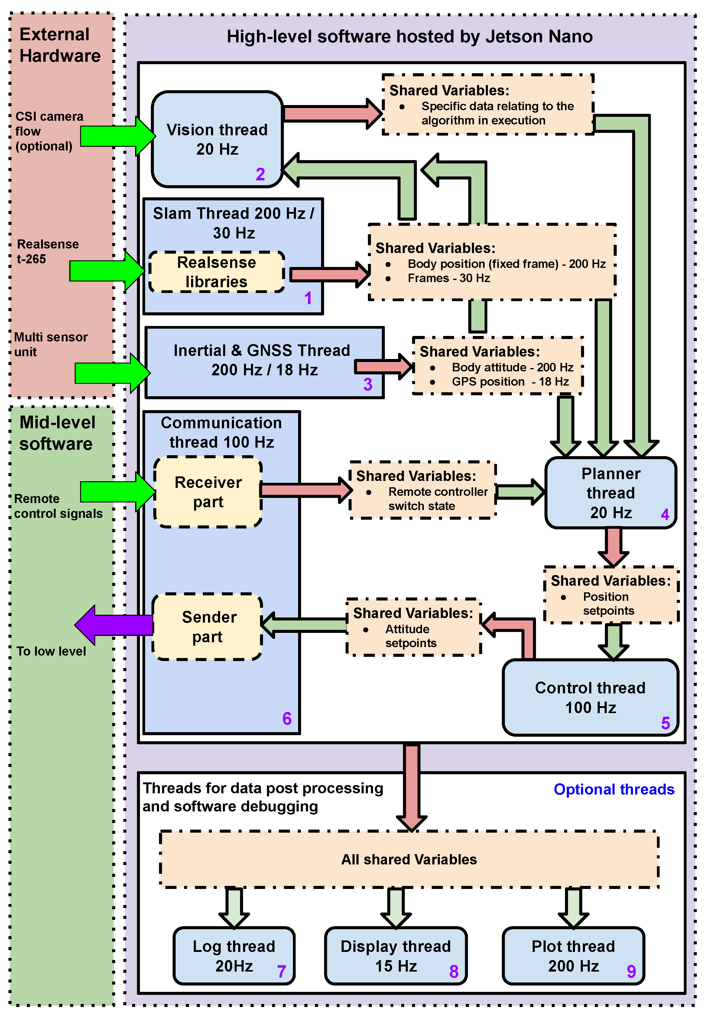
Figure 6 shows the overall software architecture, where it is possible to observe the division of the various jobs into different threads. Each thread can operate on shared variable blocks through the reader/writer sync method.
- SLAM thread.Thread 1 implements SLAM algorithms. It receives the 3D position data generated with a frequency of 200 Hz by the t-265 stereoscopic camera. These data are related to the position of the UAV in the environment and are defined in fixed frames. Thread 1 also receives the video streams of the two fish-eye lenses of the stereoscopic camera at a frequency of 30 Hz;
- Vision thread.Thread 2 receives the information computed by Thread 1 together with the additional video stream from the CSI camera. The vision thread also receives some additional data, such as the attitude, relative and absolute position given by the t-265 stereoscopic camera and by the GNSS (if available). Inside this thread, various computer vision algorithms can be implemented, such as environmental marker detection [21,22] or object recognition [23,24];
- Inertial and GNSS thread.Thread 3 provides additional information on accelerations and position to the vision thread. This information is elaborated by sensor fusion algorithms to improve the precision in the estimation of the drone position and speed.
- Planner thread.Thread 4 exploits the outputs of the previous threads to build the reference trajectory. It contains several routines for path generation, which are specific for different kinds of missions. For example, this thread is responsible for the generation of a specific path built from environmental markers, but it can also account for fixed trajectories in the space. The desired path is a sequence of vectors of four elements:which represent set points to be tracked. In particular, , , and are the desired values for, respectively, the lateral position, the altitude, the longitudinal position and the yaw angle. The comparison between and the estimated position and attitude provide the displacements from the desired trajectory.
- Control thread.Thread 5 implements the control strategy [25,26,27] of the cyber pilot with respect to the planned trajectory generated by Thread 4. The result is a sequence of vectors containing the reference values, which are sent to the flight controller implementing the low-level:In each vector , and are the set points for roll and pitch angles, is the reference value of the thrust and is the set point for the yaw rate.Many different control algorithms can be used here, depending on the mission specifications, whether for instance the UAV has to maintain a specific position (hovering) or track a complex trajectory. A quite simple but efficient control scheme implemented in this thread and tested in experiments consists of an array of double-nested loops of proportional–integral–derivative (PID) controllers that process the 3D position and velocity errors to compute the first three components of the vector, i.e., roll, pitch and thrust set points, whereas the yaw rate is left as an additional degree of freedom. In the cyber pilot paradigm, the vector contains the commands used by the mid-level software layer to overwrite the manual commands during the autonomous flight modes. It is important to stress that the signals in the vector depend on the commands accepted by the flight controller implementing the low-level. Anyway, the commands generated by the cyber pilot share their nature with those received from the human pilot during manual flight. In other words, from the flight controller point of view, these two kinds of commands look exactly the same. In this sense, the cyber pilot makes the autonomous flight system independent from the flight controller, provided that its input interface can be properly replicated.
- Communication thread.Thread 6 is devoted to sending the output of the control thread to the mid-level software layer, which, based on its policies, decides whether to use them or those coming from the human pilot. This thread also handles the inputs from the auxiliary channels of the remote controller, which regard useful information for the management of the drone and in particular for interacting with the mid-level functions.
- Log thread.
- Display thread.
- Plot Thread.Threads 7, 8 and 9 are optional and can be activated if needed. They are used to log, store and plot the shared variables, and so they are useful during the experimental phase, as they allow for acquiring data for the post processing and for the debugging phases.
2.4. Frame Sizing
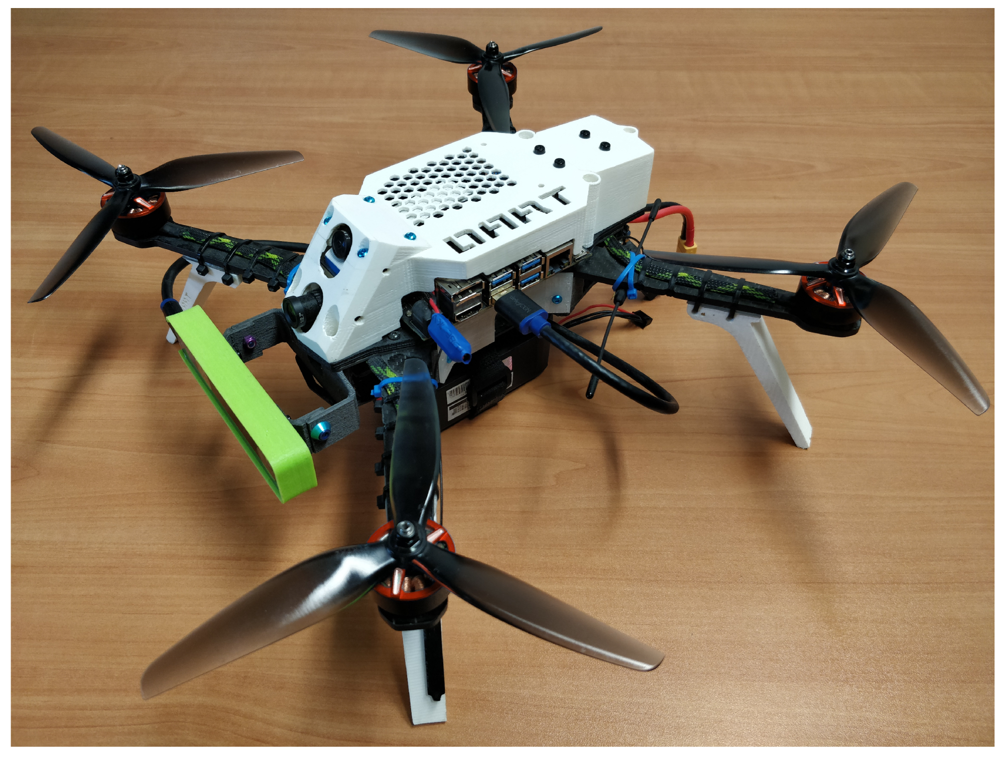
A relevant aspect for the development of the UAV used in this paper and shown in Figure 7 concerns its mechanical frame design and sizing.
In fact, there are no small drones on the mass market capable of supporting the development of high-level algorithms. Given the high performance and robustness of racing drones, it was decided to develop the UAV frame according to the same philosophy used for the construction of racing drones [28]. Normally, this type of drone has a full carbon frame, a wheelbase of 250 mm and 5-inch propellers. These drones are combined with small motors that are able to reach high rpm. Usually, 22 mm stator motors are used which can easily exceed 40,000 rpm. The high number of revolutions is necessary to achieve the desired thrust considering the small propeller diameter. Furthermore, the use of small propellers greatly decreases the inertia of the same, making these drones very reactive.
However, the additional hardware mentioned in Section 2.1 and necessary for the realization of the cyber pilot results in a weight increase of about 300 g. In theory, it would not be a problem, given that racing drones have thrust-to-weight ratios between 6:1 and 8:1. On the other hand, their typical motor/propeller set has a relatively low energy efficiency, defined as the ratio between the maximum thrust generated and the electrical power used. A lower energy efficiency has the negative effect of decreasing the battery life, which in racing drones, is already a few minutes, therefore, this phenomenon must be avoided, trying to increase the value of efficiency as much as possible. In addition, the racing drone frames available on the market do not have enough space to be used for mounting the new parts. To solve the above issues, a carbon frame was designed that can accommodate all the additional parts, whereas the wheelbase was increased to 330 mm, providing enough space for mounting 7-inch propellers. Notice that the use of larger diameter propellers is not enough to increase the energy efficiency of a drone, but it is necessary that these are suitably matched to the motors. For this purpose, motors with a stator diameter of 25 mm (instead of the usual 22 mm) capable of reaching approximately 22,000 rpm have been chosen. Even if these motors are able to reach a lower number of revolutions than those normally used for racing applications, the larger stator diameter allows for an increase in the lever arm, which guarantees higher torque values suitable for the use of 7-inch propellers. These considerations have been made on the basis of data-sheets provided by the various motor manufacturers, which among other data, also provide the power consumed and the thrust obtained depending on the type of propeller and the type of battery used.
3. Results
The implementation illustrated thus far of the proposed architecture was tested in a challenging mission consisting of a circular trajectory of specified shape to be followed in an indoor environment. The difficulty of such a mission is due to the availability and accuracy of data from the traditional sensors (i.e., GNSS, inertial measurement unit (IMU), compass and barometer) in small indoor environments. Indeed, GNSS is just not available, the compass is negatively affected by the building structure, the barometer has insufficient precision in small places, and the IMU alone is, in general, not well suited for navigation because of the well-known problem of drifting. Such a situation is perfect to check whether the VBN techniques exploited in the proposed solution are able to recover from that loss of accuracy. Indeed, it is worth stressing that the cyber pilot has a three-dimensional perception of the environment, which makes it capable of following generic 3D trajectories, thanks to the t-265 stereoscopic camera.
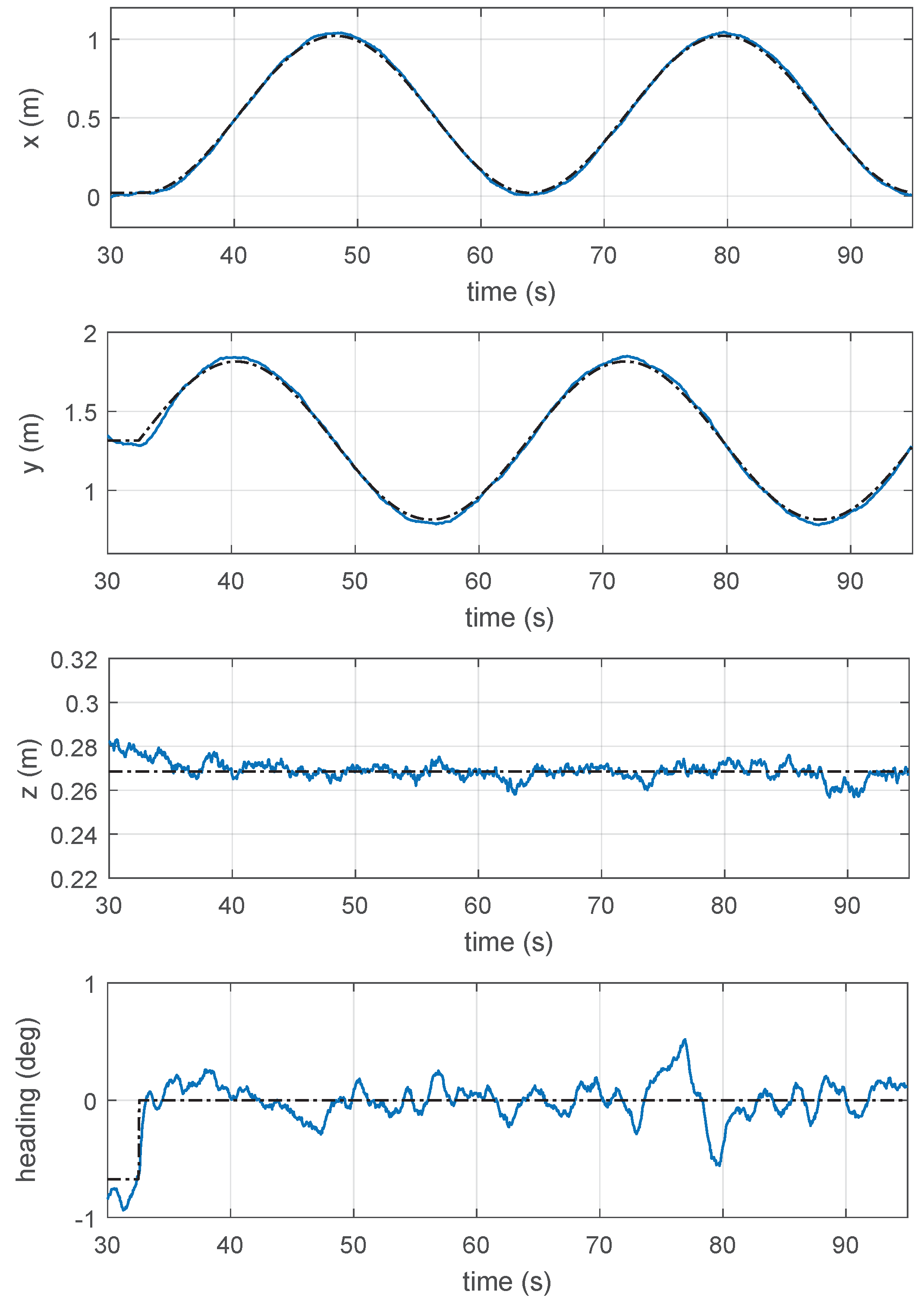
In Figure 8, the blue line shows the trend of the UAV position on the single degrees of freedom, while the dashed black line defines the desired trajectory.
The actual configuration of the mission can be programmed within the planner thread, whose role, as mentioned in Section 2.3, is to generate the desired trajectory. In particular, the circular trajectory is defined as a relative path starting from the initial position of the drone and position on the vertical plane orthogonal to the heading. Its radius and the traveling (constant) speed are the two tuning parameters, and for these field tests, they have been set to 0.5 m and 0.1 m/s, respectively. Such a mission was performed in repeated experiments to record statistics on the drone performance. Figure 8 shows the 3D position x, y, z of the drone against the corresponding set-points. The position is directly measured by the t-265 Realsense camera in a fixed frame where the y axis represents the drone altitude while x–z lie on the horizontal normal plane.
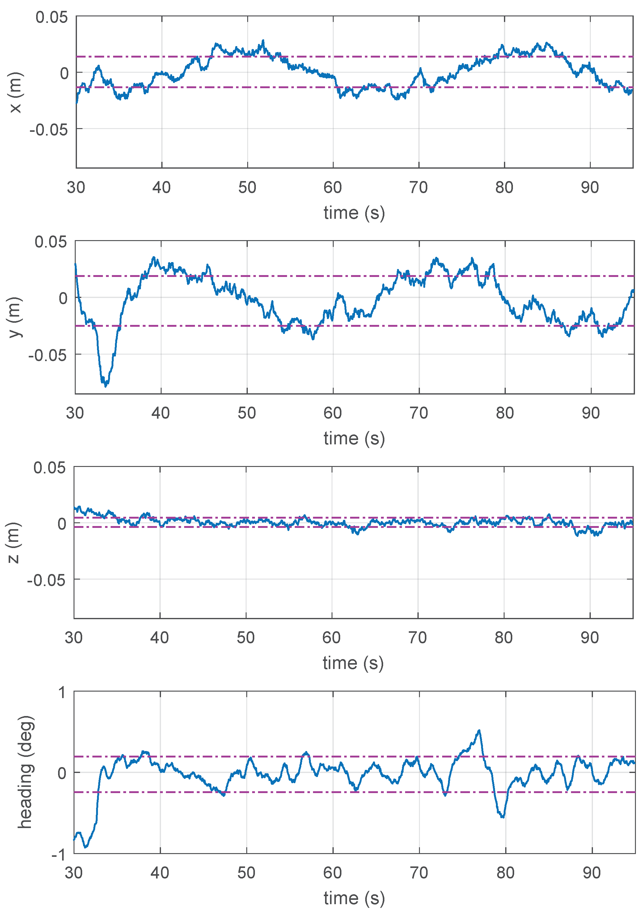
The actual trajectory lies in the x–y plane and it follows the reference path with high accuracy. In Figure 9, the position errors are shown, confirming the small overshoots nearly visible in Figure 8. The following table reports the statistics of the errors computed on the entire set of experiments.
| Axis | std |
| horizontal (along x) | 1.36 cm |
| altitude (along y) | 2.20 cm |
| longitudinal (along z) | 0.42 cm |
| yaw | 0.22 deg |
It should be noted that the lowest standard deviations are relative to the degrees of freedom that remained constant in the experiment (z axis and orientation angle). However, even the standard deviations obtained along the axes of the x–y plane are very small and highlight the good performance achievable by the architecture presented in this paper.
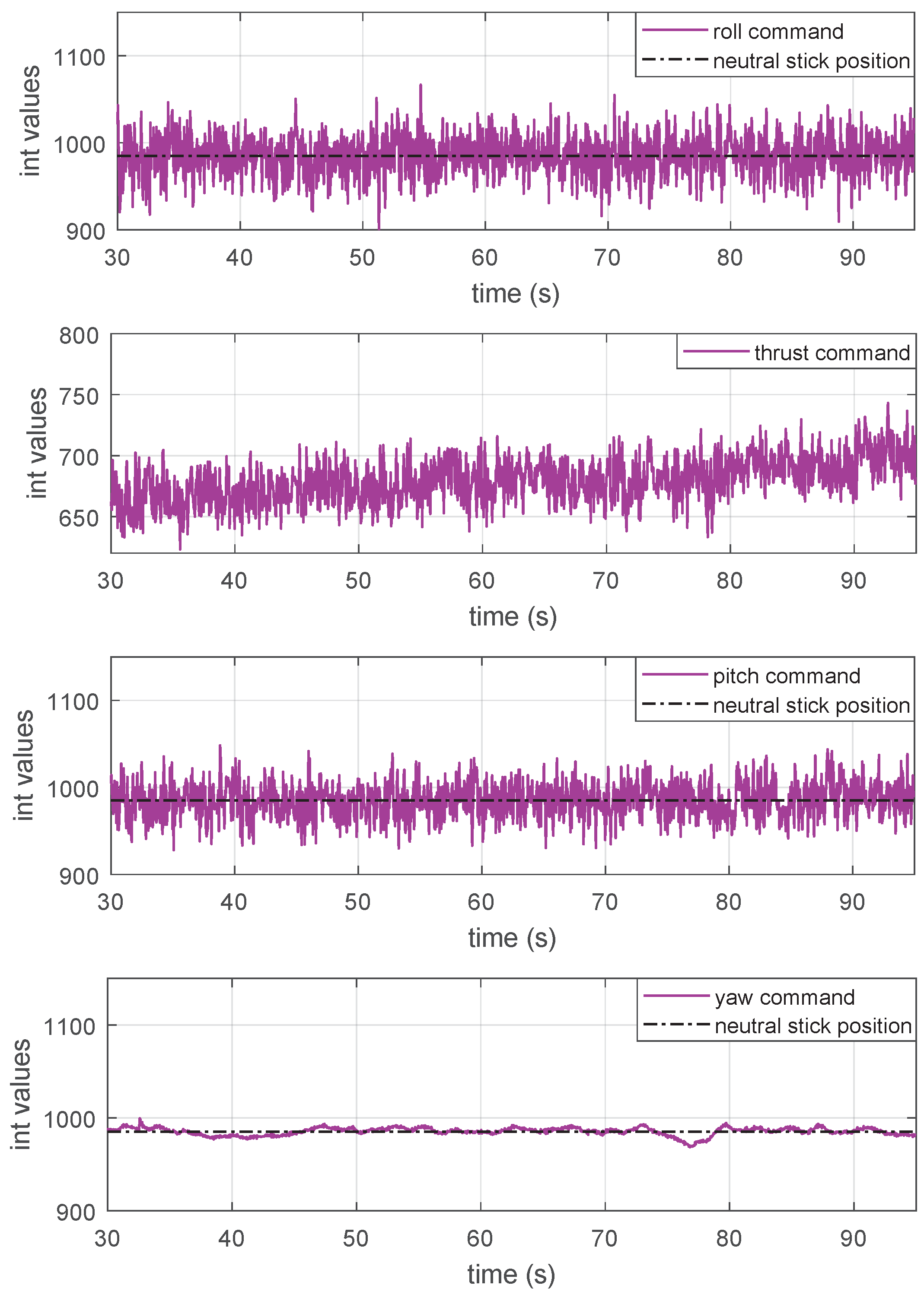
Figure 10 reports the SBUS commands sent to the flight controller and synthetically generated by the cyber pilot. These commands are the vector defined in Equation (2) which replace the manual flight commands of the human pilot. It is interesting to note the high information content they possess, thanks to the fact that the cyber pilot is able to exploit the entire bandwidth of the SBUS protocol. These commands are very different from a human operator, as the latter is unable to generate commands with a frequency higher than 2–3 Hz.
The black dotted line shows the neutral position of the remote control sticks, and as can be seen in Figure 10, both the pitch, roll and yaw commands are close to the central values, while the thrust commands generated by the cyber pilot are lower than the neutral value. This is because the UAV used has a thrust-to-weight ratio higher than the usual 2:1 ratio, which is normally used in non-racing drones.
Another interesting aspect that can be observed in Figure 10 relates to the trend of the thrust commands over time, whose average tends to increase. This happens because the cyber pilot is able to compensate for the battery discharge curve, and to do so, it increases the average value of the thrust commands. This is clearly a byproduct of the feedback control strategy based on the position error.
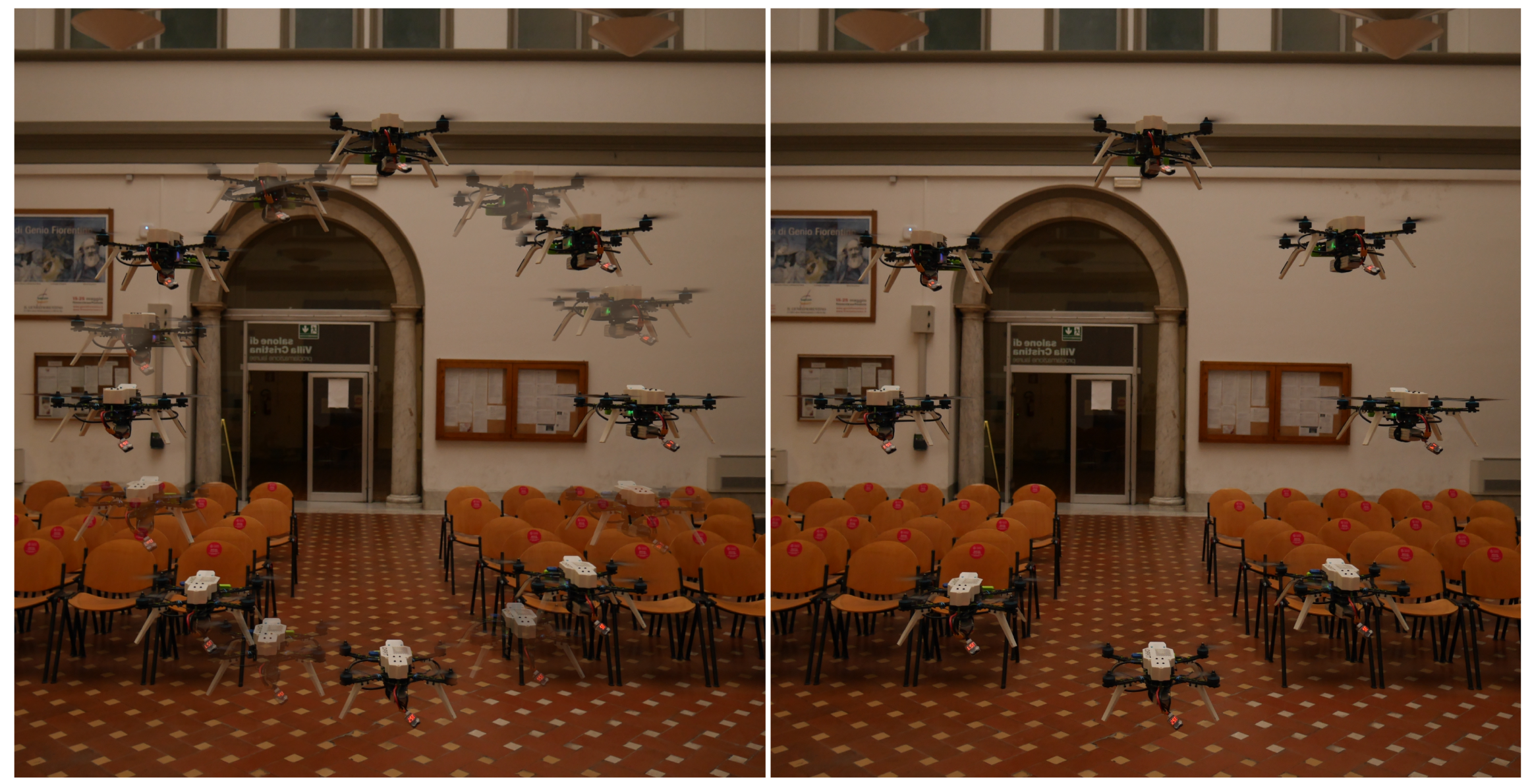
Figure 11 shows the UAV during the execution of the preset mission. The image has been generated by superimposing several shots, taken at almost uniformly distributed shooting times. The image shows the high precision reached by the drone, and it also gives a good idea of the correct tracking of the desired velocity, since the drone is in the correct position in every shot.
4. Discussion
The experimental tests show that the system presented in this paper is able to follow the desired trajectories with centimeter precision. In particular, all the experiments highlighted that the tracking accuracy is not imposed by the measurements of the onboard sensors (IMU and camera), whose error is in the order of under a millimeter, but is mainly limited by the propellers’ turbulence, which act as disturbances that the controller is unable to completely reject. Figure 11 shows the repeatability of the test mission, since the UAV is able to track the same trajectory several times. Given the nature of the optical sensors used, the drone can follow 3D trajectories with controlled velocity and acceleration. In the literature, most works employ motion capture systems (mocap) [6,7] for the development of indoor autonomous navigation algorithms [8]. The achievable accuracy of these systems is very high, although they can only work in environments suitably set up by external computers and fixed cameras that frame the drone. This limits autonomous navigation to the environment monitored by the mocap system only.
In this paper, an alternative approach was conceived that allows to achieve similar performance, with the difference that all sensors and computing units are mounted on-board. This feature ensures high flexibility and the ability to operate in a wide variety of environments, without the need to use off-board sensors and computing units. The experiment shown in Section 3 was carried out with the sole purpose of demonstrating the capabilities of the developed architecture, in fact, thanks to the modular nature of the high-level software, the mission objectives can be easily modified by calling different routines within the planner thread. On the other hand, if the purpose of the research concerns the development of computer vision algorithms, it will be sufficient to write additional routines that can be called up by the vision thread.
Another aspect of fundamental importance, which will be very useful for future research, is the possibility of replicating the same communication protocol used by the radio link during manual flights. This peculiar feature, as discussed in previous sections, allows the development of cyber pilot missions in specific scenarios. In the future, this aspect can be used for the development of algorithms based on neural networks and AI, able to learn from the human pilot and to replicate similar command signals. A second development path will be that of the autonomous exploration of buildings based on the use of depth sensors, such as the Intel D4xx camera series [12]. Thanks to the addition of these devices, it will be possible to develop on-board 3D mapping algorithms of the environment, thus making the UAV capable of detecting obstacles and targets of interest in complete autonomy and without ground assistance.
Author Contributions
Conceptualization L.B., M.B., E.B., G.I. and M.P.; data curation L.B.; formal analysis L.B. and M.B.; funding acquisition M.B., E.B., G.I. and M.P.; investigation L.B., M.B. and E.B.; methodology L.B., M.B. and G.I.; project administration M.B., G.I. and M.P.; software L.B.; supervision M.B., E.B., G.I. and M.P.; writing—original draft L.B., M.B. and G.I.; writing—review and editing L.B., M.B., E.B., G.I. and M.P. All authors have read and agreed to the published version of the manuscript.
Funding
This research was co-funded by Horizon 2020, European Community (EU), AURORA (Safe Urban Air Mobility for European Citizens) project, ID number 101007134.
Institutional Review Board Statement
Not applicable.
Informed Consent Statement
Not applicable.
Data Availability Statement
The data presented in this study are available in the supplementary material of the article.
Acknowledgments
Thanks to Lapo Miccinesi for the help given in the acquisition of the photos during the laboratory tests.
Conflicts of Interest
The authors declare no conflict of interest.
References
- Grabe, V.; Bülthoff, H.H.; Scaramuzza, D.; Giordano, P.R. Nonlinear ego-motion estimation from optical flow for online control of a quadrotor UAV. Int. J. Robot. Res. 2015, 34, 1114–1135. [Google Scholar] [CrossRef] [Green Version]
- Penin, B.; Spica, R.; Giordano, P.R.; Chaumette, F. Vision-based minimum-time trajectory generation for a quadrotor UAV. In Proceedings of the 2017 IEEE/RSJ International Conference on Intelligent Robots and Systems (IROS), Vancouver, BC, Canada, 24–28 September 2017. [Google Scholar]
- Al Habsi, S.; Shehada, M.; Abdoon, M.; Mashood, A.; Noura, H. Integration of a Vicon camera system for indoor flight of a Parrot AR Drone. In Proceedings of the 2015 10th International Symposium on Mechatronics and Its Applications (ISMA), Sharjah, United Arab Emirates, 8–10 December 2015. [Google Scholar]
- Gargioni, G.; Peterson, M.; Persons, J.B.; Schroeder, K.; Black, J. A Full Distributed Multipurpose Autonomous Flight System Using 3D Position Tracking and ROS. In Proceedings of the 2019 International Conference on Unmanned Aircraft Systems (ICUAS), Atlanta, GA, USA, 11–14 June 2019. [Google Scholar]
- Antonio-Toledo, M.E.; Sanchez, E.N.; Alanis, A.Y.; Flórez, J.A.; Perez-Cisneros, M.A. Real-Time Integral Backstepping with Sliding Mode Control for a Quadrotor UAV. In Proceedings of the (IFAC-PapersOnLine) 2nd IFAC Conference on Modelling, Identification and Control of Nonlinear Systems MICNON 2018, Guadalajara, Jalisco, Mexico, 20–22 June 2018. [Google Scholar]
- Masiero, A.; Fissore, F.; Antonello, R.; Cenedese, A.; Vettore, A. A comparison of UWB and motion capture UAV indoor positioning. In Proceedings of the The International Archives of the Photogrammetry, Remote Sensing and Spatial Information Sciences, SPRS Geospatial Week 2019, Enschede, The Netherlands, 10–14 June 2019. [Google Scholar]
- Xiao, X.; Dufek, J.; Suhail, M.; Murphy, R. Motion Planning for a UAV with a Straight or Kinked Tether. In Proceedings of the 2018 IEEE/RSJ International Conference on Intelligent Robots and Systems (IROS), Madrid, Spain, 1–5 October 2018. [Google Scholar]
- Aguilar, W.G.; Manosalvas, J.F.; Guillén, J.A.; Collaguazo, B. Robust Motion Estimation Based on Multiple Monocular Camera for Indoor Autonomous Navigation of Micro Aerial Vehicle. In Proceedings of the International Conference on Augmented Reality, Virtual Reality, and Computer Graphics (AVR 2018), Otranto, Italy, 14 July 2018. [Google Scholar]
- Basso, M.; Bigazzi, L.; Innocenti, G. DART Project: A High Precision UAV Prototype Exploiting On-board Visual Sensing. In Proceedings of the 15th International Conference on Autonomic and Autonomous Systems (ICAS), Athens, Greece, 2–6 June 2019. [Google Scholar]
- Bigazzi, L.; Basso, M.; Gherardini, S.; Innocenti, G. Mitigating latency problems in vision-based autonomous UAVs. In Proceedings of the 29th Mediterranean Conference on Control and Automation (MED2021), Bari, Puglia, Italy, 22–25 June 2021. [Google Scholar]
- Ceron, A.; Mondragon, I.; Prieto, F. Onboard visual-based navigation system for power line following with UAV. Int. J. Adv. Robot. Syst. 2018, 15, 2–12. [Google Scholar] [CrossRef] [Green Version]
- Lu, L.; Redondo, C.; Campoy, P. Optimal Frontier-Based Autonomous Exploration in Unconstructed Environment Using RGB-D Sensor. Sensors 2020, 20, 6507. [Google Scholar] [CrossRef] [PubMed]
- Ma, C.; Zhou, Y.; Li, Z. A New Simulation Environment Based on Airsim, ROS, and PX4 for Quadcopter Aircrafts. In Proceedings of the 2020 6th International Conference on Control, Automation and Robotics (ICCAR), Singapore, 20–23 April 2020. [Google Scholar]
- Hinas, A.; Roberts, J.M.; Gonzalez, F. Vision-Based Target Finding and Inspection of a Ground Target Using a Multirotor UAV System. Sensors 2017, 17, 12. [Google Scholar]
- Atoev, S.; Kwon, K.R.; Lee, S.H.; Moon, K.S. Data analysis of the MAVLink communication protocol. In Proceedings of the 2017 International Conference on Information Science and Communications Technologies (ICISCT), Tashkent, Uzbekistan, 2–4 November 2017. [Google Scholar]
- Kwon, Y.M.; Yu, J.; Cho, B.M.; Eun, Y.; Park, K.J. Empirical Analysis of MAVLink Protocol Vulnerability for Attacking Unmanned Aerial Vehicles. IEEE Access 2018, 6, 43203–43212. [Google Scholar] [CrossRef]
- Madgwick, S.O.H. An efficient orientation filter for inertial and inertial/magnetic sensor arrays. April 2010. [Google Scholar]
- Mahony, R.; Hamel, T.; Pflimlin, J.M. Nonlinear Complementary Filters on the Special Orthogonal Group. IEEE Trans. Autom. Control 2008, 53, 1203–1218. [Google Scholar] [CrossRef] [Green Version]
- Bigazzi, L.; Gherardini, S.; Innocenti, G.; Basso, M. Development of Non Expensive Technologies for Precise Maneuvering of Completely Autonomous Unmanned Aerial Vehicles. Sensors 2021, 21, 391. [Google Scholar] [CrossRef] [PubMed]
- Gardner, W.; Brown, W.; Chen, C.-K. Spectral Correlation of Modulated Signals: Part II—Digital Modulation. IEEE Trans. Commun. 1987, 35, 595–601. [Google Scholar] [CrossRef]
- Olson, E. AprilTag: A robust and flexible visual fiducial system. In Proceedings of the 2011 IEEE International Conference on Robotics and Automation, Shanghai, China, 9–13 May 2011. [Google Scholar]
- Wang, J.; Olson, E. AprilTag2: Efficient and robust fiducial detection. In Proceedings of the 2016 IEEE/RSJ International Conference on Intelligent Robots and Systems (IROS), Daejeon, Korea, 9–14 October 2016. [Google Scholar]
- Kechagias-Stamatis, O.; Aouf, N.; Nam, D. 3D Automatic Target Recognition for UAV Platforms. In Proceedings of the 2017 Sensor Signal Processing for Defence Conference (SSPD), London, UK, 6–7 December 2017. [Google Scholar]
- Vujasinovic, S.; Becker, S.; Breuer, T.; Bullinger, S.; Scherer-Negenborn, N.; Arens, M. Integration of the 3D Environment for UAV Onboard Visual Object Tracking. Appl. Sci. 2020, 10, 7622. [Google Scholar] [CrossRef]
- Antonelli, G.; Cataldi, E.; Giordano, P.R.; Chiaverini, S.; Franchi, A. Experimental validation of a new adaptive control scheme for quadrotors MAVs. In Proceedings of the 2013 IEEE/RSJ International Conference on Intelligent Robots and Systems, Tokyo, Japan, 3–7 November 2013. [Google Scholar]
- Koubaa, A.; Taher Azar, A. Unmanned Aerial Systems: Theoretical Foundation and Applications. Advances in Nonlinear Dynamics and Chaos (ANDC); Academic Press: Cambridge, MA, USA, 2021. [Google Scholar]
- Sutton, A.; Fidan, B.; van der Walle, D. Hierarchical UAV Formation Control for Cooperative Surveillance. IFAC Proc. 2008, 41, 12087–12092. [Google Scholar] [CrossRef] [Green Version]
- Castiblanco, J.M.; Garcia-Nieto, S.; Simarro, R.; Salcedo, J.V. Experimental study on the dynamic behaviour of drones designed for racing competitions. Int. J. Micro Air Veh. 2021. [Google Scholar] [CrossRef]
Figure 1.
Standard UAV architecture: the flight controller is directly connected to the receiver, GNSS and ESCs (electronic speed controllers).
Figure 1.
Standard UAV architecture: the flight controller is directly connected to the receiver, GNSS and ESCs (electronic speed controllers).

Figure 2.
Proposed multilevel architecture, where the Jetson Nano computer is connected between the flight controller and the drone receiver.
Figure 2.
Proposed multilevel architecture, where the Jetson Nano computer is connected between the flight controller and the drone receiver.

Figure 3.
A pictorial representation of the two analog protocols used as a communication standard for commercial UAV receivers. On the left, it is possible to observe the signal generated through the PWM standard, while on the right, a frame generated through the PPM standard is shown [20].
Figure 3.
A pictorial representation of the two analog protocols used as a communication standard for commercial UAV receivers. On the left, it is possible to observe the signal generated through the PWM standard, while on the right, a frame generated through the PPM standard is shown [20].

Figure 4.
This figure shows the frame architecture according to the SBUS standard, which unlike the two previous standards, is a digital protocol. Being the latest protocol developed in the UAV field, it is currently the best choice for sending commands to the flight controller, as in addition to guaranteeing a greater useful band, it is not affected by noise.

Figure 5.
Diagram showing one of the mid-level operating policies. In the specific case, during the transition to the flight modes managed by the cyber pilot, the mid-level operates by replacing only the channels necessary for piloting the UAV.
Figure 5.
Diagram showing one of the mid-level operating policies. In the specific case, during the transition to the flight modes managed by the cyber pilot, the mid-level operates by replacing only the channels necessary for piloting the UAV.

Figure 6.
The figure shows the high-level software architecture, where all the threads that can be executed according to the type of mission to be performed are defined. Note that the inter-thread synchronization method implemented is based on the reader/writer model.
Figure 6.
The figure shows the high-level software architecture, where all the threads that can be executed according to the type of mission to be performed are defined. Note that the inter-thread synchronization method implemented is based on the reader/writer model.

Figure 7.
The autonomous UAV prototype implementing the multilevel architecture is presented in this paper. The frame is fully carbon fiber and was designed to host the Nvidia Jetson Nano board and all the additional electronics. Given the increase in weight due to the new elements, the frame was designed to allow the installation of 7-inch propellers.

Figure 8.
The black dashed lines show the desired trajectories along the 4 degrees of freedom of the UAV, while the blue lines show the trend of the position of the UAV along the three axes and its orientation.
Figure 8.
The black dashed lines show the desired trajectories along the 4 degrees of freedom of the UAV, while the blue lines show the trend of the position of the UAV along the three axes and its orientation.

Figure 9.
This figure shows the error trends as a function of time. The sinusoidal trend of the errors relating to the x–y plane—which is the plane where the drone carries out the mission with a circular trajectory—is also observed.
Figure 9.
This figure shows the error trends as a function of time. The sinusoidal trend of the errors relating to the x–y plane—which is the plane where the drone carries out the mission with a circular trajectory—is also observed.

Figure 10.
This figure shows the commands that the cyber pilot sends to the flight controller through the SBUS protocol managed by the mid-level. The commands are encoded in 16-bit integer variables.
Figure 10.
This figure shows the commands that the cyber pilot sends to the flight controller through the SBUS protocol managed by the mid-level. The commands are encoded in 16-bit integer variables.

Figure 11.
Circular mission task: the right image shows the UAV that correctly tracks a circle with a diameter of 1 m and a constant speed of 0.1 m/s. In the left image, the positions taken by the UAV during the execution of a second lap of the trajectory have been superimposed “in transparency”. As it is possible to observe, the trajectories followed by the drone are perfectly reproducible.

Publisher’s Note: MDPI stays neutral with regard to jurisdictional claims in published maps and institutional affiliations. |
© 2021 by the authors. Licensee MDPI, Basel, Switzerland. This article is an open access article distributed under the terms and conditions of the Creative Commons Attribution (CC BY) license (https://creativecommons.org/licenses/by/4.0/).
Share and Cite
MDPI and ACS Style
Bigazzi, L.; Basso, M.; Boni, E.; Innocenti, G.; Pieraccini, M. A Multilevel Architecture for Autonomous UAVs. Drones 2021, 5, 55. https://0-doi-org.brum.beds.ac.uk/10.3390/drones5030055
AMA Style
Bigazzi L, Basso M, Boni E, Innocenti G, Pieraccini M. A Multilevel Architecture for Autonomous UAVs. Drones. 2021; 5(3):55. https://0-doi-org.brum.beds.ac.uk/10.3390/drones5030055
Chicago/Turabian StyleBigazzi, Luca, Michele Basso, Enrico Boni, Giacomo Innocenti, and Massimiliano Pieraccini. 2021. "A Multilevel Architecture for Autonomous UAVs" Drones 5, no. 3: 55. https://0-doi-org.brum.beds.ac.uk/10.3390/drones5030055