CAD-Based Automated Design of FEA-Ready Cutting Tools
by
 , and
, and
Anastasios Tzotzis
1,* ,
,
César García-Hernández
1,
José-Luis Huertas-Talón
1 and
Panagiotis Kyratsis
2,*
1
Department of Design and Manufacturing Engineering, University of Zaragoza, 50018 Zaragoza, Spain
2
Department of Product and Systems Design Engineering, University of Western Macedonia, 50100 Kozani, Greece
*
Authors to whom correspondence should be addressed.
J. Manuf. Mater. Process. 2020, 4(4), 104; https://0-doi-org.brum.beds.ac.uk/10.3390/jmmp4040104
Submission received: 12 October 2020
/
Revised: 25 October 2020
/
Accepted: 30 October 2020
/
Published: 1 November 2020
Abstract
:The resources of modern Finite Element Analysis (FEA) software provide engineers with powerful mechanisms that can be used to investigate numerous machining processes with satisfying results. Nevertheless, the success of a simulation, especially in three dimensions, relies heavily on the accuracy of the cutting tool models that are implemented in the analyses. With this in mind, the present paper presents an application developed via Computer-Aided Design (CAD) programming that enables the automated design of accurate cutting tool models that can be used in 3D turning simulations. The presented application was developed with the aid of the programming resources of a commercially available CAD system. Moreover, the parametric design methodology was employed in order to design the tools according to the appropriate standards. Concluding, a sample tool model was tested by performing a number of machining simulations based on typical cutting parameters. The yielded results were then compared to experimental values of the generated machining force components for validation. The findings of the study prove the functionality of the tool models since a high level of agreement occurred between the acquired numerical results and the experimental ones.
Keywords:
CAD-based programming; automated design; API; SolidWorks; FEA; cutting tool; turning insert1. Introduction
Nowadays, investigations on machining processes can benefit from the implementation of two dimensional or three dimensional Finite Element (FE) modelling. Especially, 3D FE modelling is considered to be a valuable asset during complicated investigations since it provides accurate results and allows the user to fully represent a problem. However, in order to properly carry out 3D simulations and yield acceptable results, it is imperative to define the problem with as much detail as possible. One of the most important aspects during FE model setup is the representation of the cutting tool in three dimensions, so that the full geometry of the tool can be analyzed. In the case of turning, the tool’s micro-geometry seems to have a great impact on the generated numerical results. With the advent of more advanced Computer-Aided Design (CAD) systems, it is possible to utilize the Application Programming Interface (API) and the parametric modelling to develop macros, applets or even software tools that can support numerous engineering processes such as the design and manufacturing of machine components, the inspection of manufacturing quality, as well as the integration of CAD, Computer-Aided Manufacturing (CAM) and Computer-Aided Engineering (CAE).
Wu et al. [1] presented an integration of CAD and CAE for the generative design of face gears. This method uses a comprehensive algorithm that calculates the points as an even distribution on the tooth surface of a gear which can facilitate the stress analysis process during Finite Element Analysis (FEA). Wang et al. [2] studied the prediction of tool deflection of end-mills by integrating CAD, CAE and CAM systems. Using the developed CAD model, authors managed to measure the distributed cutting forces along the tool axis via FE modelling of the cutting process. Bartłomiej [3] described a tool for analyzing the tooth contact and transmission errors of spiral bevel gear sets with tooth flanks. The tool was developed via a CAD system and is used for the analysis of meshing of spiral bevel gears prior to FEA. A number of studies prove that the APIs can be useful to the manufacturing-related area of research also. García-Hernández et al. [4] proposed a method to manufacture elliptical and oval gears using Wire Electro-Discharge Machining (WEDM). Authors presented the mathematical models and simulations based on CAD and CAM systems. Similarly, Tzivelekis et al. [5] proposed a novel approach for automating both the design and manufacturing processes of impeller-type geometries. For this reason, authors developed an application based on API programming of commercially available CAD/CAM software. Oancea and Haba [6] presented a new software tool which allows the user to obtain the manufacturing sequences and cutting data of a manufacturing process and in addition can be used for the simulation setup of these processes. Moreover, the tool was developed with Visual Lisp and is particularly helpful for rotational parts. Dimitriou et al. [7] described an effective simulation of gear hobbing, based on virtual kinematics of CAD models. The algorithm was developed and embedded in a commercial CAD software by using the modern programming resources available. According to authors, the resulting 3D data allow the prediction of the cutting forces, tool stresses, and wear development that can be used for the optimization of the gear hobbing process. With similar strategies that were implemented with a modern CAD system, Kyratsis et al. [8] developed DRILL3D application which can estimate the thrust forces that develop on both the main edges and chisel edge of a drill simultaneously. Thus, any equivalent lab work may be skipped. In addition to the automated design, CAD-based automated planning of manufacturing processes is a possibility [9,10,11,12,13], as well as the automation and enhancement of the assembly processes of engineering parts by taking advantage of the programming resources that modern CAD systems have to offer. Typical examples in this area involve the automated assembly process of large mechanical systems based on characteristics and features, as well as the extraction of the assembly sequences via CAD models for assembly planning [14,15,16,17].
The benefits and the possibilities that derive from the use of the APIs of modern CAD systems are vast. Engineers can increase their productivity and focus on more critical aspects of a project instead of spending time on repetitive and frustrating tasks. One such task is the design of cutting tools that can be implemented in FEA projects, especially when multiple geometric parameters are involved. Vijayaraghavan and Dornfeld [18] developed algorithms and a graphical interface that were used to design a complete application based on CAD programming. The aforementioned application deals with the automated drill modelling that can be implemented in commercial FEA software. Similarly, Li et al. [19] proposed the optimization method of critical parameters of solid end mills, based on 3D FE simulations, providing a design system for end mills. In light of these considerations, the present paper describes a CAD-based application that can be used to generate CAD models of standardized turning inserts. The application was developed with the aid of the SolidWorks™ API and the Visual Basic for Applications (VBA) programming language. Furthermore, the proposed design methodology complies with the parametric-based structure of the used CAD environment. The tools that are designed by the described application are solid, consistent models including the full geometry and can be easily converted to FE-ready file formats. Finally, a set of 3D simulations was carried out by utilizing the FEA software DEFORM™-3D to verify the functionality of the generated models and investigate their performance.
2. Materials and Methods
2.1. Description of Turning Inserts
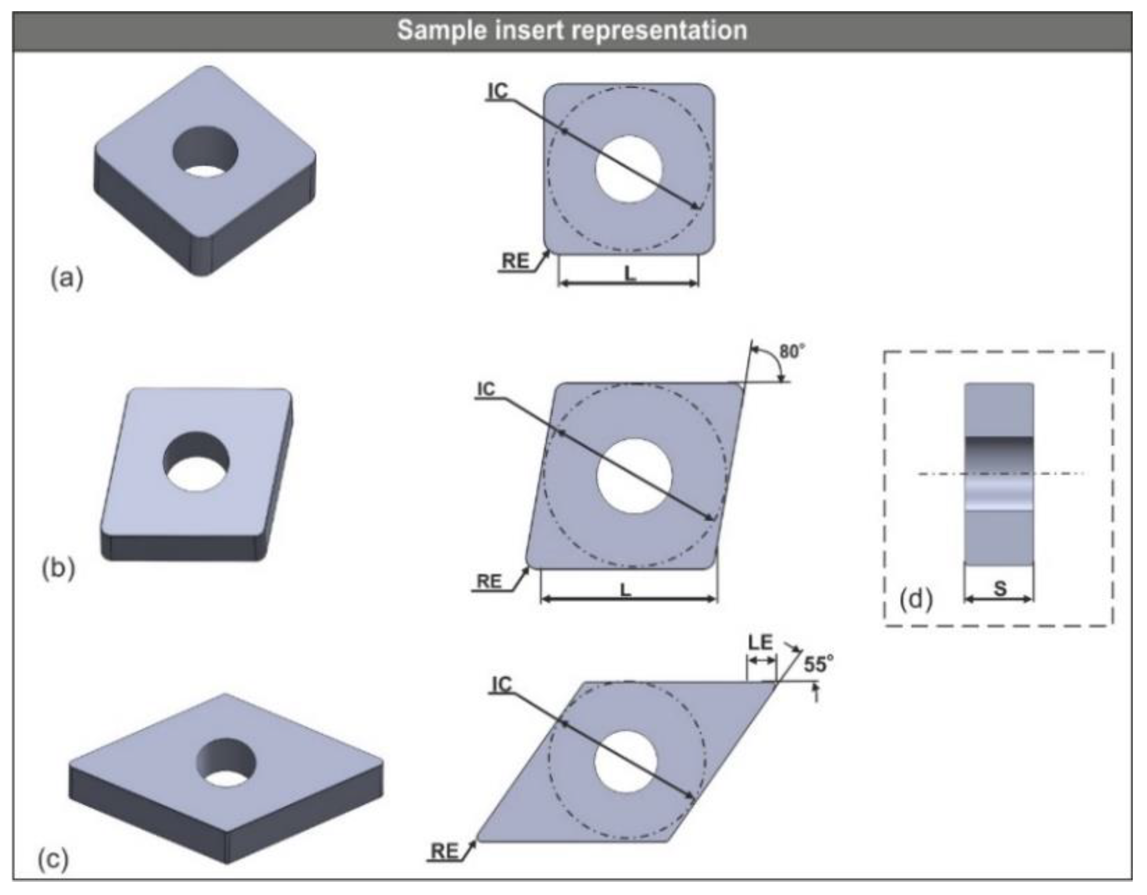
The principal geometric parameters of the modern turning inserts can be found in the product catalogues of most manufacturers. Furthermore, ISO 13399 provides a schema for cutting tools description including turning inserts. Despite the fact that modern cutting tools are standardized, some details such as the combinations of chamfer width and chamfer angle that relate to the turning inserts still differ from manufacturer to manufacturer. This means that a great number of possible tool variations is available. Figure 1 illustrates three commonly-used turning inserts that are used during machining of industry-standard materials such as hardened steel, cast iron and aluminum alloys: the insert of square shape with designation number SNGA120412S01525 (Figure 1a), the 80° rhombic CNGA120408T01020 (Figure 1b) and the 55° rhombic DNGA150404S01020 (Figure 1c), respectively. The symbol IC represents the inscribed diameter, RE is the corner radius, S denotes the thickness, L is the theoretical cutting edge length and finally LE is the cutting edge effective length.
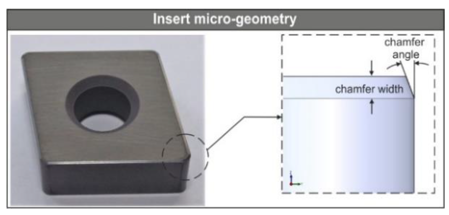
Nevertheless, these are not the only parameters that define the full geometry of a turning insert. Figure 2 depicts a standardized 80° rhombic insert with its micro-geometry which comprises the cutting edge type, the chamfer angle and the chamfer width. In addition to the corner radius, the aforementioned parameters are crucial because they greatly affect the cutting forces during machining [20,21,22,23]. Moreover, according to Denkena et al. [24] the cutting edge micro-geometry affects the tool life significantly due to changes in the characteristic tool wear behavior.
Modern turning inserts are manufactured in such a way that they can withstand extreme forces and temperatures. To meet these criteria, most inserts are coated via Chemical Vapour Deposition (CVD) or Physical Vapour Deposition (PVD). Most common coatings are the Titanium Nitride (TiN), the Titanium Carbide (TiC) and the Aluminium Oxide (Al2O3). Moreover, the commonly used material for the manufacturing of inserts is the Cubic Boron Nitride (CBN) which is the hardest material in the world, second to diamond [25].
2.2. Design of the User Interface
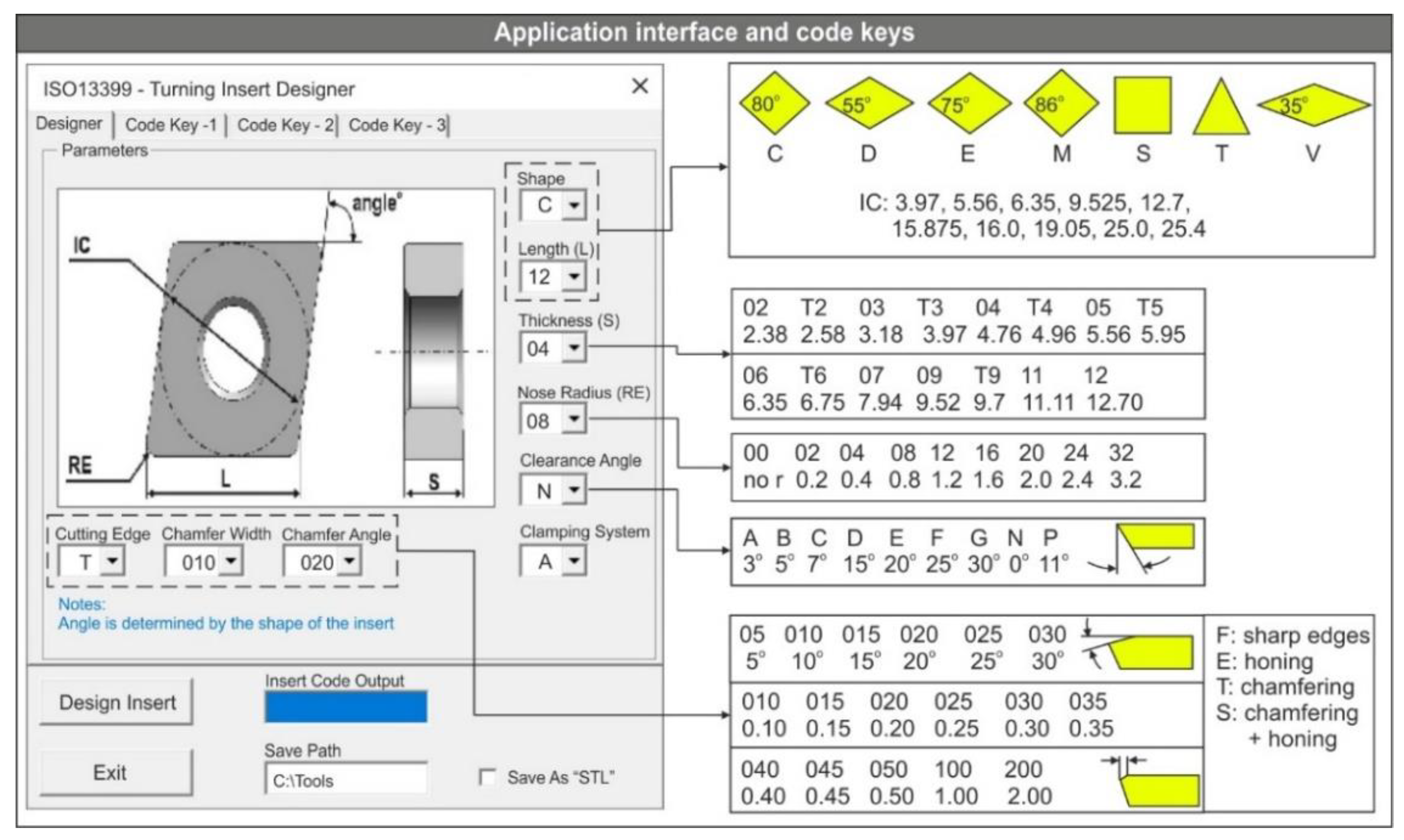
The embedded toolbox of the SolidWorks™ API was used to design the user interface. The idea was to design a simple interface with easy parameter selection and visually conveyed information about the geometric aspects of the inserts. It is possible to generate a wide variety of tools since the user can change every available design parameter. In order to keep the code simple and to avoid developing multiple large modules, a few insert shapes and some special options were skipped from the present study. In addition, no input was provided for the tolerance class, which refers to the manufacturing tolerance of the tool’s dimensions and does not affect the designed CAD model, since any dimension of the CAD model is represented exactly as it is designed. The third digit in the standardized coding of inserts denotes the tolerance class. For example, in the CNGA120408 tool, the “G” digit corresponds to a tolerance class of ±0.025 for both the nose height and the inscribed circle, and ± 0.13 for the thickness. Figure 3 illustrates the main tab of the application’s user interface along with the code keys that correspond to the standardized design parameters such as shape, length, thickness, nose radius, clearance angle, micro-geometry and clamping system. Nine combo-boxes were used to facilitate the selection procedure. Each combo-box contains a variety of options according to its function. For example, the combo-box entitled “Shape” defines the shape of the insert and contains seven choices as dictated by the detail in Figure 3: five versions of the diamond-shaped with a corner angle of 80°, 55°, 75°, 86° and 35°, respectively; a triangular-shaped; and finally a square. This combo-box, along with the combo-box entitled “Length (L)” determine the shape, the corner angle and the size of the insert, which are the most basic geometric aspects. Specifically, the “Length (L)” combo-box contains ten choices that correspond to the inscribed circle diameter in mm. For the selection of the appropriate variables, the user may consult the tabs entitled “Code Key-1”, “Code Key-2” and “Code Key-3” (see Figure 3) correspondingly to acquire the necessary explanations of the input parameters. On top of that, the main tab includes a schematic with the critical dimensions that further visualizes the parameter input process. Finally, a text-box was included so that the user can choose the folder where the generated models can be saved both in native format (SLDPRT) and in STL. With the command button entitled “Design Insert” the design process may begin and the desired model can be generated within seconds. Additionally, a non-editable text-box was included with the title “Insert Code Output”, in order to display the designation number of the generated tool for reference purposes.
2.3. Modelling Procedure of Turning Cutting Tools
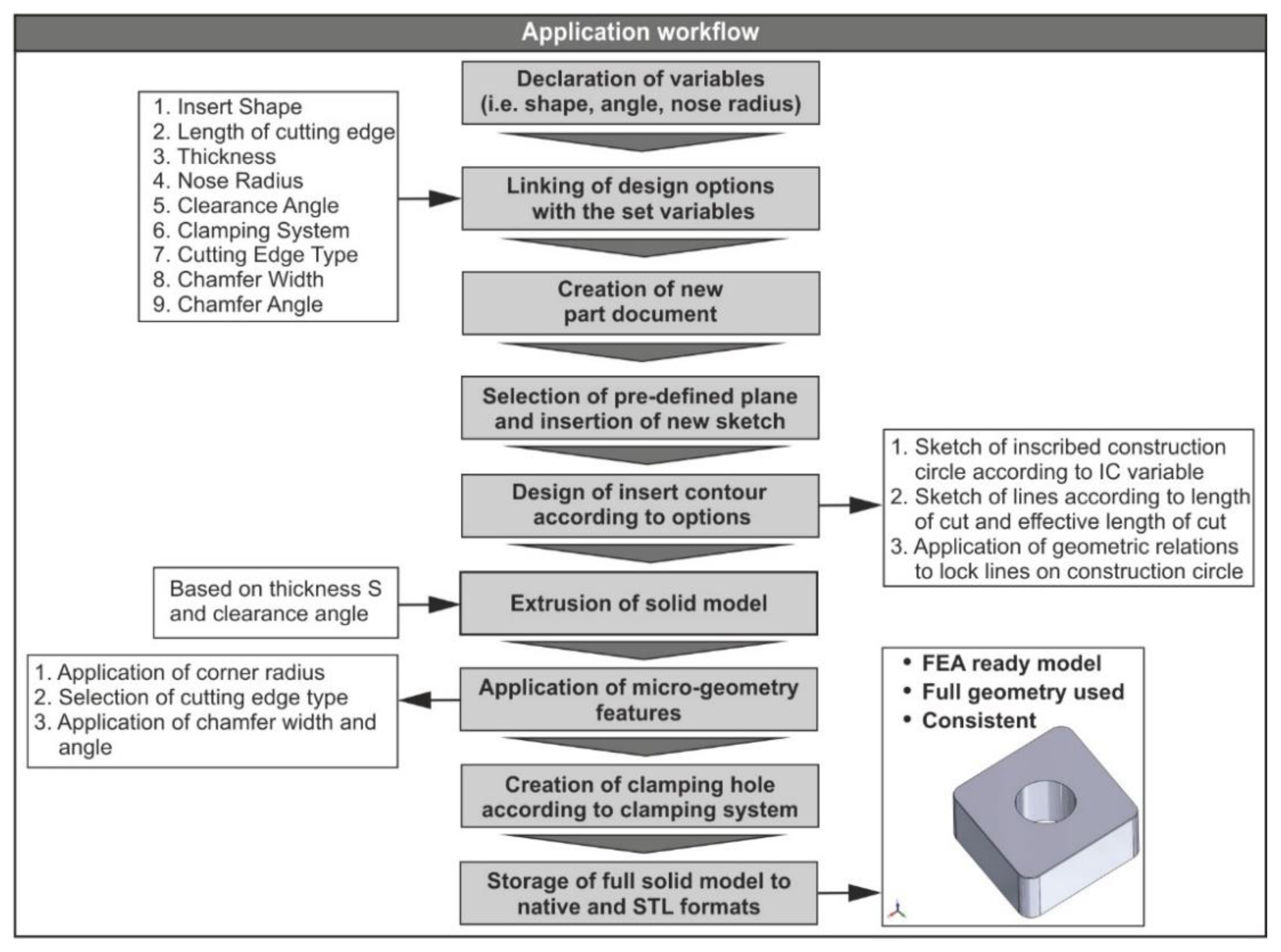
The development of the presented application was performed via the API of SolidWorks™. In addition, the programming language implemented is VBA which derives from Microsoft™ Visual-Basic™ 6. Due to the fact that SolidWorks™ uses a feature-based parametric methodology during 3D modelling, the workflow of the application’s code follows similar principals. According to Figure 4, the declaration of the necessary variables is the first step that is performed when the “Design Insert” button is pressed. These variables correspond to each of the geometric aspects that were presented in Figure 3 such as the shape, the inscribed circle, the corner angle and the corner radius. Next, the declared variables are linked to the input and output controls (i.e., combo-boxes) of the interface to secure that the design process can initialize without errors. Additionally, all the input controls are populated with a pre-defined set of choices according to the standardized design framework. Even though it is relatively simple to alter the code in such a way that an option to generate customized inserts can also become available, it is not of great significance. However, the application allows the user to input custom values for the parameters that relate to the cutting edge, since some variations exist between different manufacturers. To do so, three simple text-boxes were included to enable insertion of custom values. Additionally, the text-boxes were locked so that only reasonable values could be inputted to prevent variable-based errors during the design process. For the employment of the shape according to the user selection, the “Select…Case” statement was used. This statement provides a more convenient way of condition checking, compared to the “If-Then-Else” statement, especially when a large number of conditions are available. With the declaration of the variables, a new part document is created and activated so that new sketches can be inserted. The used methods for the aforementioned actions are the “ActiveDoc” and “NewDocument”, respectively. Subsequently, the front plane is selected, and a new sketch is activated. The selection of the sketch plane is always standard, based on the default coordinate system that most FEA software share. Then, the design process of the insert’s contour is carried out according to the selected design scheme. The design process includes the sketch of the inscribed circle (“CreateCircleByRadius” method) and the sketch of the contour lines (“CreateLine” method), and finally the application of both the dimensions (“AddDimension2” method) and the geometric relations (“SketchAddConstraints” method) that fully define the contour. Later, the base solid model is produced according to the selected thickness and the clearance angle. For this action, the “FeatureExtrusion2” method is used. In order to acquire the complete solid model, micro-geometry is applied: the corner radii are created with the “FeatureFillet3” method, and the cutting edge is formed by using both the “InsertFeatureChamfer” and the “FeatureFillet3” methods depending on whether the selected edge type requires honing, chamfering or both. Because these methods require the automatic selection of the corresponding topology (i.e., edge), a “For” loop initiates that is responsible for traversing all available topology objects of the solid model that relate to the fillet and chamfer features. In particular, the code locates and recognizes all faces and edges of the solid model; next, it changes the default ID of each one of the objects to a pre-defined tag that comprises a prefix, such as “Edge” and a numerical suffix. This means that if a model contains fifteen edges they will be renamed “Edge” plus a number from one to fifteen. Lastly, all new IDs are stored to an array so that they can be accessed by the program at any time. The automated topology selection is an indispensable part of similar applications [26]. Last but not least, the center hole is created according to the selected clamping system. This feature does not play an important role during the FE analysis, rather it is used for more accurate representation of the cutting tool in a CAD-based layout of the turning process that includes a tool-holder. Upon finalizing the generated CAD model, the last step is the storage of the model to file formats that are used for FE analyses (i.e., “STL”), as well as to “SLDPRT” format that is the SolidWorks™ native format for part documents.
To ensure that no discrepancies will occur after the data translation, the highest possible level of resolution was set during the model conversion (angle tolerance of 0.5° and deviation tolerance of 0.0009968 mm), leading to finer tessellation as well as to greater accuracy. Moreover, to keep the file size at a reasonable level (less than 500 kB on average), the Binary model output was chosen. Even though the generated STL models proved to be robust and consistent since they were flawlessly imported to the FEA software, their consistency was verified with a free-to-use mesh processing system, namely MeshLab. The models were checked for gaps, holes, non-manifolds, intersecting geometry and other faults. As expected, the models were found to be error-free. This result is enhanced by the fact that morphologic errors [27] are caused mainly due to structural heterogeneity [28], which would probably create errors during the translation of a model from one proprietary format to another, but not in this case.
Table 1 and Table 2 include the most basic API methods that were implemented during the development of the presented application, along with their functionality and return value. Most of these methods require a number of parameters to be set in order to function properly. The way of implementing each of the API methods can be found in the online help of SolidWorks™ API [29].
The following examples describe the implementation of some API methods used in the presented application. The “CreateCircleByRadius” method that is used to design the inscribed circle, is syntaxed as follows: “value = instance.CreateCircleByRadius(XC, YC, ZC, Radius)”. In addition, the appropriate variables are declared, in order for the method to function properly. The variables XC, YC and ZC represent the center of the circle, whereas Radius is the value of the circle’s radius. Furthermore, the variable instance represents the ISketchManager interface that provides access to sketch-creation routines. Lastly, the variable value denotes the sketch segment. Similarly, the “CreateLine” method requires this syntax: “value = instance.CreateLine(X1, Y1, Z1, X2, Y2, Z2)”. The variables are all the same except the X1, Y1, Z1, X2, Y2 and Z2 that represent the coordinates of the line start point and the coordinates of the line end point, respectively. To obtain the bodies of a part, the “GetBodies2” method is used in this manner: “value = instance.GetBodies2(BodyType, BVisibleOnly)”. In this case, the variable instance represents the IPartDoc interface that provides access to functions that perform operations on parts in part documents. The variable BodyType defines the type of body, whereas the BVisibleOnly defines which bodies will be included depending on their visibility. Finally, the variable value is an object. The last example shows the syntax of the “GetEdges” method: “value = instance.GetEdges()”, the variable value is an object and the variable instance denotes the IFace2 interface that allows access to the underlying edge, loop of edges and other data of a body.
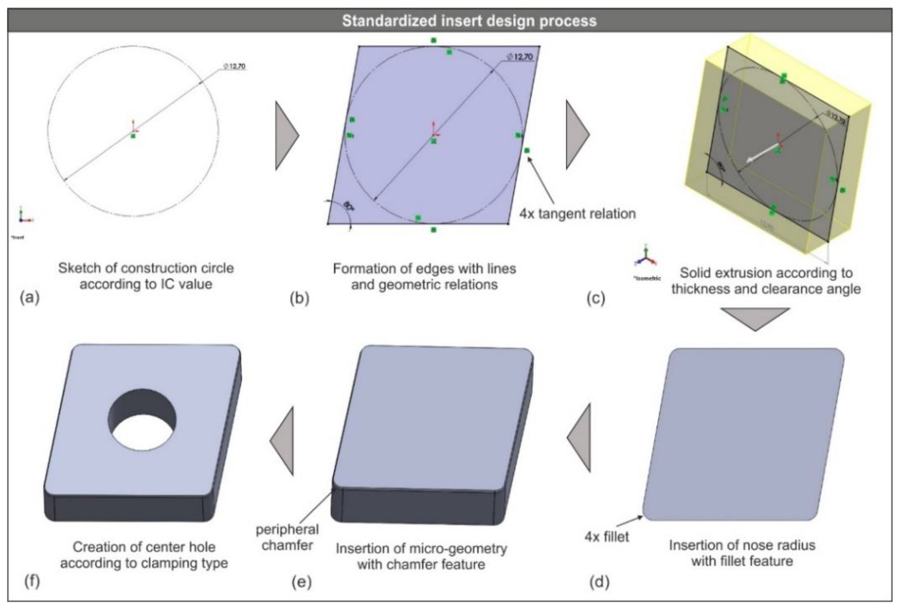
Even though the modelling procedure of the turning inserts is rather simple compared to the one of drills, it is still critical that a manufacturing-oriented modelling strategy is followed so that the generated models are error-free. First of all, the design sequence applied, so that the model tree remains simple no matter the design parameters, plus, the geometric constraints are always locked. This way, the generated models are free of semantic errors [27]. The simple model tree is achieved by creating a base feature that resembles the contour of the tool and then adding the rest of the design features on top of the base, instead of creating a cubic solid and then trying to remove material. On the other hand, the minimum use of constraints, in addition to the application of the appropriate type of constraint, ensures that the sketch is fully-defined at all times. Hence, the relationship between the designed objects, which derives from the design intent, allows for an automated propagation of any design change to the objects. Figure 5 illustrates the aforementioned modelling technique applied to a standardized type of inserts (CNGA). Specifically, Figure 5a depicts the initial step of the design process. At first, the front plane of the part document is selected because it is important to define a coordinate system that will serve through the FE analysis [22]. Hence, the Z-axis must be parallel to the tangential force vector, the Y-axis must be parallel to the radial force vector and finally, the X-axis must be parallel to the feed force vector. Next, a sketch of a construction circle is inserted with diameter equal to the IC variable value. The IC variable represents the diameter of the inscribed circle of the insert (see Figure 1). This circle is determined by both the type of the insert (shape) and the length of cutting edge. However, not all cutting length values are available for all types of inserts during standardized design process. For example, the cutting length of the diamond-shaped insert (type C) can be designed in six sizes: 6.35, 9.525, 12.7, 15.875, 19.05 and 25.0 mm, respectively.
Figure 5b depicts the next step during the design process which is the insertion of an appropriate number of line sketches (four for this case) that form the selected shape of the tool. Then, the equivalent number of tangent geometric relations is applied between the sketched lines and the construction circle. Moreover, the corner angle is applied based on the corresponding variable value (80° for the diamond-shaped inserts). Because of the used design method and due to the fact that the sketched lines form a closed contour, it is ensured that the upcoming solid model will be consistent. In fact, the formed contour is always a tangential quadrilateral, except for the cases of square and triangle, with varying edge length determined by Equation (1).
where x is the length of the edge, r denotes the inradius and α is the corner angle. With the closed contour, the solid model is created based on the selected thickness and cutting edge (Figure 5c). In this case, thickness is equal to 4.76 mm and cutting edge equal to zero. Consequently, the corner radius is applied (Figure 5d) to all cutting points of the insert according to the selected value. The full cutting geometry of the insert is completed with the design of the cutting edge (Figure 5e). The cutting edge is formed according to the selected cutting edge type, chamfer width and chamfer edge (see Figure 3). The final step in the design process is the creation of the center hole (Figure 5f) that is used for the clamping of the insert to the tool-holder. This feature, however, does not affect the FE model setup.
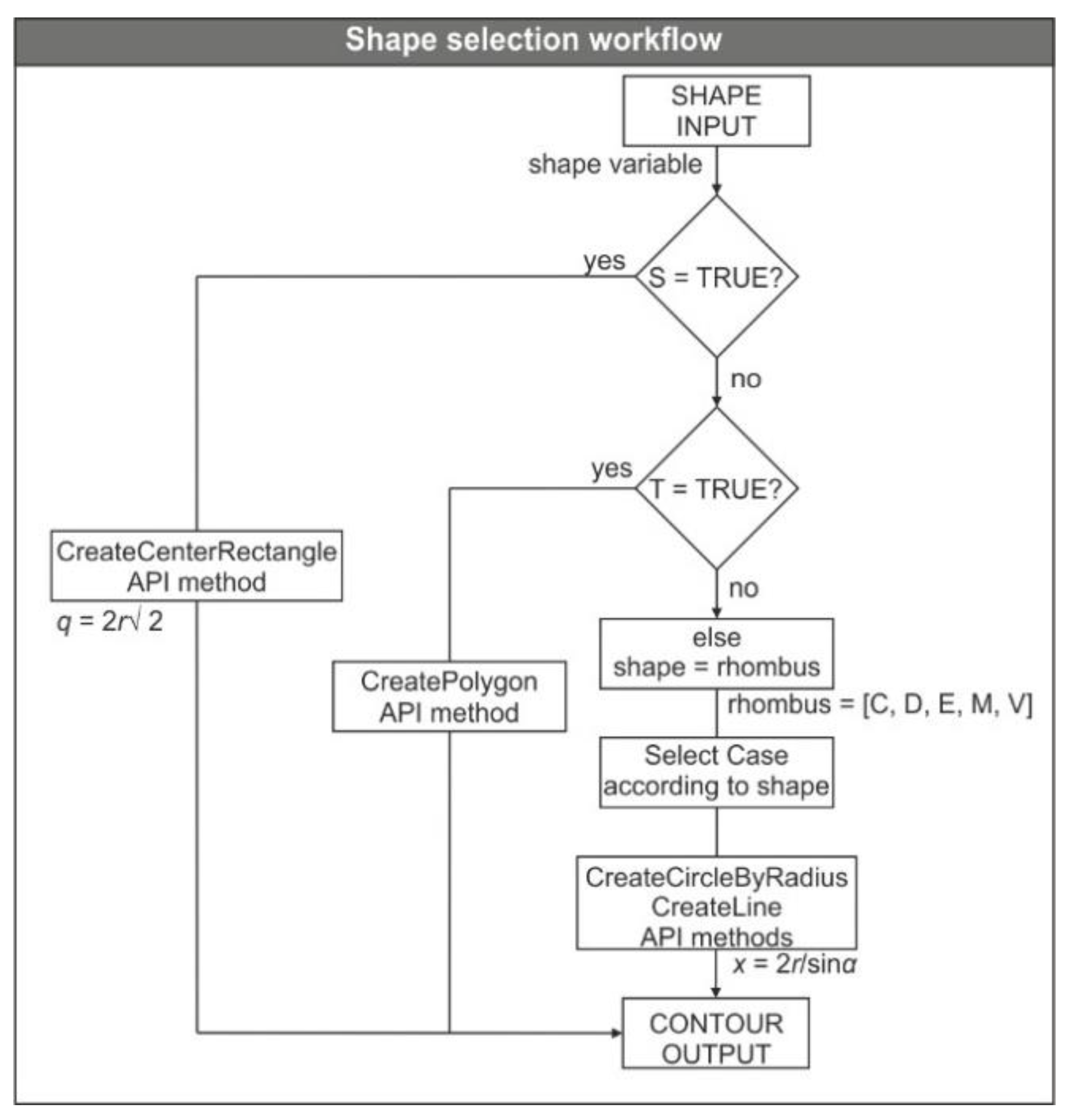
Just before the initiation of the sketch design process, a simple algorithm (Figure 6) performs a check on the shape so that the angles and geometric relations can be applied accordingly. In the case of a square insert, the algorithm skips the tangential quadrilateral shape and uses a center rectangle instead, whereas in the case of a triangular insert, it uses a polygon sketch with three edges so that the triangle can be formed. For the first case, the diagonal q must be determined, while for the latter just the inradius.
3. Results and Discussion
3.1. Testing of the Generated Cutting Tool Models
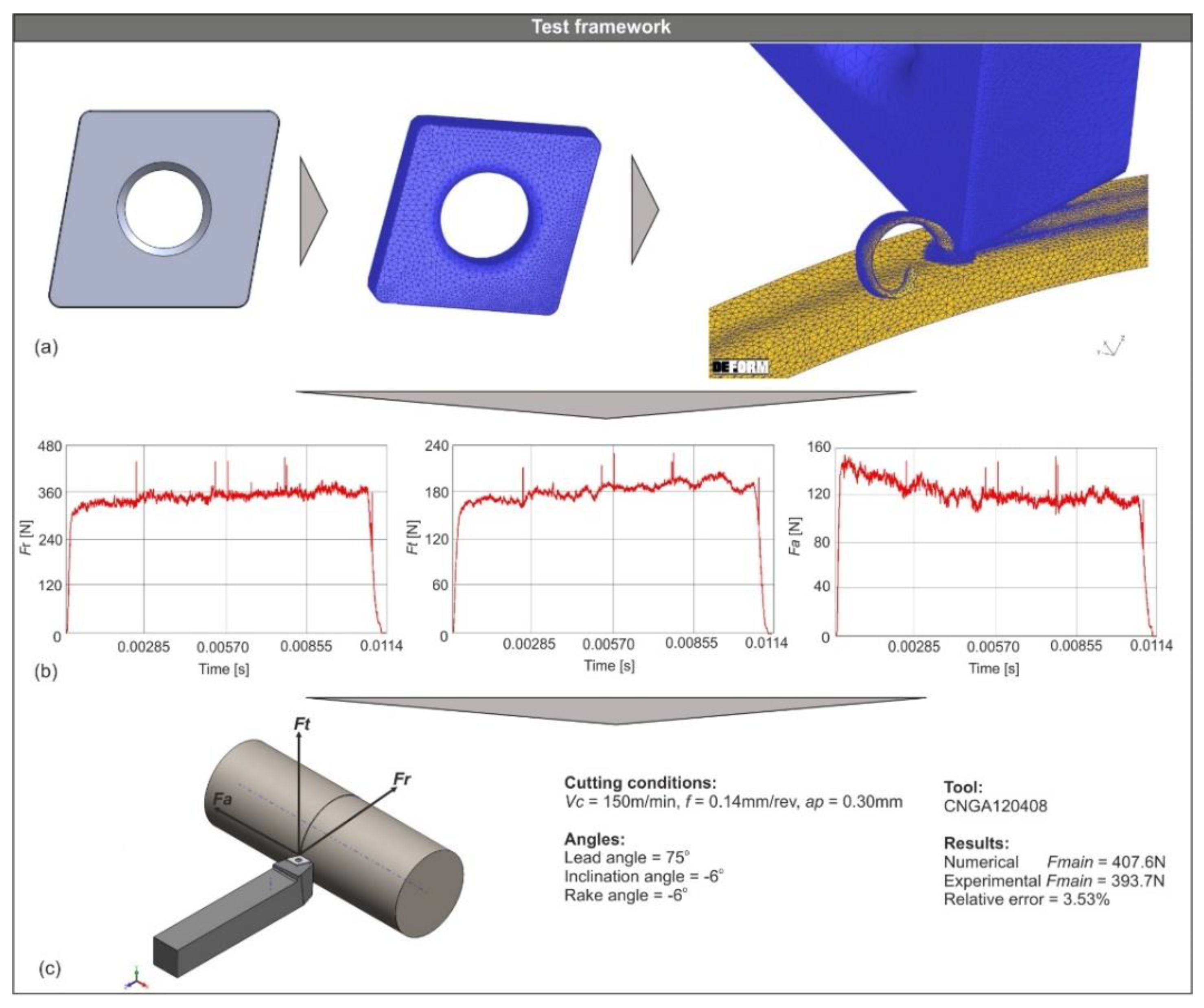
In order to validate the functionality of the generated models, an FE model was set and nine 3D turning simulations were carried out. Because the verification of the generated models is a time-consuming process, the test setup was prepared according to widely-used parameters and settings. The selected cutting tool, material and cutting conditions, have already been successfully studied [30,31,32] and thus, were chosen for this study. The test framework is shown in Figure 7. A sample generated cutting tool with its full geometry (Figure 7a) was saved in STL file format and then imported to DEFORM™-3D ver. 12 for the development of the FE model. It was modelled as rigid and meshed with approximately 50,000 tetrahedral elements. On the other hand, the mesh size of the workpiece varied according to the value of feed. The size of the minimum element was fixed to 25% of the feed for all tests [33]. Additionally, the selected workpiece material is AISI-4140 steel. During the validation tests, the tool used is the CNGA120408 (corner radius of 0.8 mm) and the cutting conditions applied are the produced combinations of the three levels of cutting speed Vc (80, 115 and 150 m/min) and feed f (0.08, 0.11 and 0.14 mm/rev) at depth of cut ap = 0.30 mm. Regarding the cutting angles used, the lead angle is 75° and both the rake and inclination angles are negative with a value of −6°. The simulation tests yielded relatively accurate results both for the cutting forces and the chip formation since the level of convergence for all simulation tests was adequate, considering that most of the FE model parameters such as the material properties, the flow stress constants and the friction coefficients were kept to their default values. Figure 7b illustrates three sample force versus time diagrams at the specified conditions (Vc = 150 m/min, f = 0.14 mm/rev) proving that cutting forces reached the steady state as expected. Furthermore, Figure 7c presents the results for the resultant machining force of the aforementioned test compared to the equivalent experimental one demonstrating an increased level of correlation. The simulated results were compared to experimental values for the same cutting conditions, in order to further examine the validity of the generated CAD models.
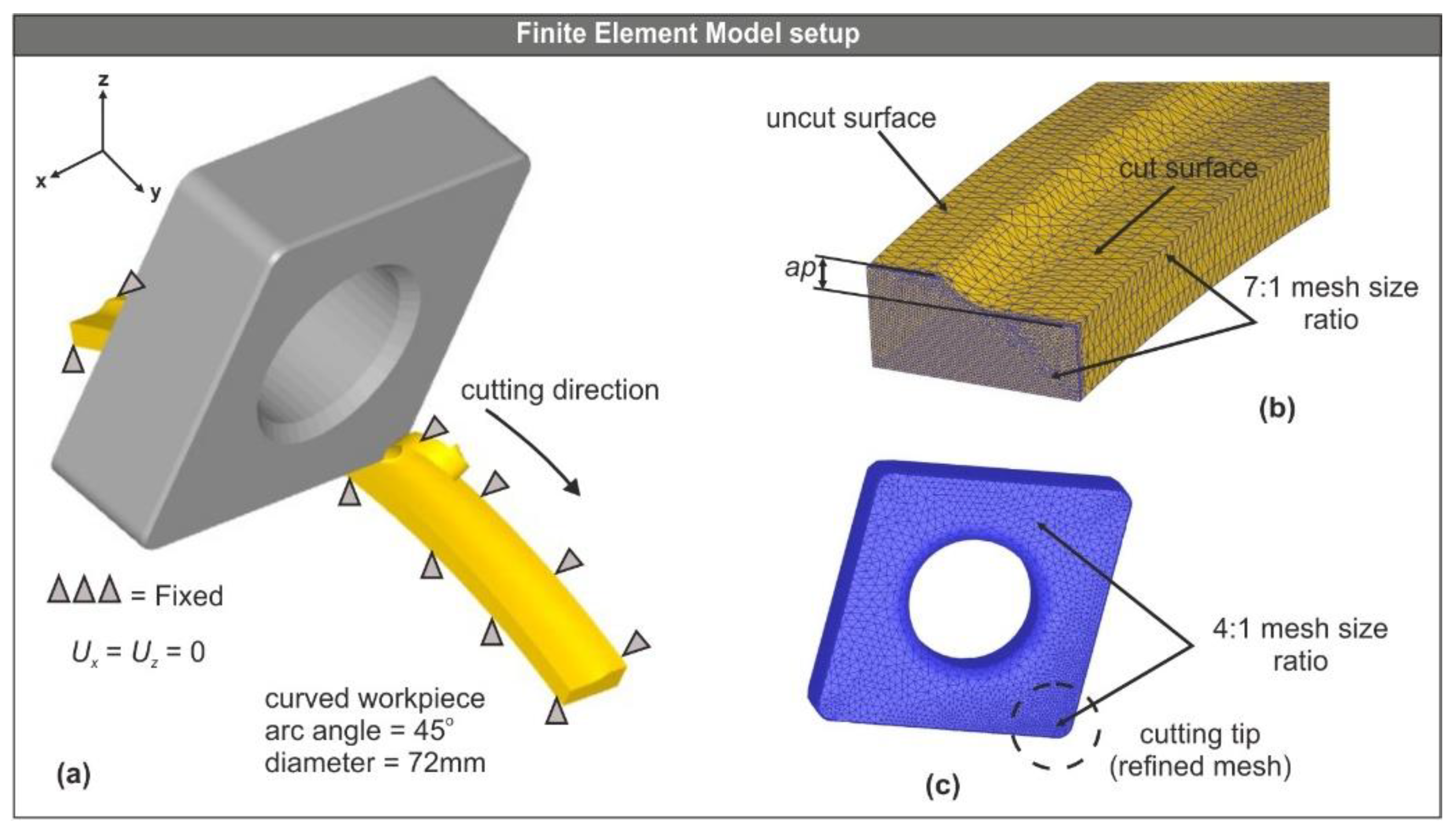
The complete model setup is shown in Figure 8a. The workpiece was designed in such a way that it resembles a fraction of the cylindrical bar. A more dense mesh with a size ratio of 7:1 was applied to the section of the workpiece where the cutting process takes place. Figure 8b illustrates the analysis domain. An effort was made to keep it as simplified as possible. Additionally, to better approximate the contact interface between the tool and the workpiece, the mesh on the tool was refined locally at the cutting tip by applying a ratio of 4:1 [33], as illustrated in Figure 8c.
The velocity of the nodes in X and Z axis was set to zero by fixing the workpiece, as shown in Figure 8a. In contrast, the displacement of the tool was allowed by following the trajectory dictated by the cutting direction. Additionally, the boundary conditions for the heat exchange with the environment were applied to all surfaces of the workpiece. The default values of heat transfer coefficient for both convection and conduction were used, as provided by DEFORM™-3D. Hence, the heat transfer coefficient via convection was set to 0.02 N/(s × mm × °C) for dry cutting and via conduction was set to 45 N/(s × mm × °C).
To simulate the friction situation at the tool–workpiece interface, Coulomb’s law [33] was used. During machining, the interaction between the bodies of both the tool and the workpiece is a complex problem due to the very high contact pressures that develop. In this case, Coulomb’s friction model was selected for its simplicity and because it provides a good approximation of the generated friction forces induced at the sliding zone, which constitutes the main area of interest in machining simulations.
3.2. Comparison of the Obtained Results
Table 3 contains the results of the nine numerical tests compared to the equivalent experimental ones. The experimental values were obtained from the literature [32]. The turning experiments were carried out with the aid of a universal lathe type SN 40C and the tool-holder with ISO designation number PCBNR2525M12. The chemical composition of the AISI-4140 steel in wt% is as follows: C 0.43, Mn 0.79, Si 0.24, S 0.024, Cu 0.025, Al 0.029, Ti 0.004, Nb 0.001, Ni 0.022, Cr 1.10, Mo 0.19, Va 0.005, Sn 0.002 and Fe in balance. Additionally, the chemical composition of the used tool with ISO designation number CNGA120408 (ceramic) is 70% Al2O3 and 30% TiC. According to Table 2, all nine tests yielded good results when compared to the experimental ones. However, it is reasonable that in an FE model some discrepancies might occur. In the present study, this is notable mostly in the tangential component where the Mean Absolute Percentage Error (MAPE) is close to 20% in some cases. Despite this fact, the comparison between the numerical and the experimental results of the calculated resultant turning force is in high accordance in most tests. This is proved by an MAPE below 10% for eight out of nine tests and an average MAPE of approximately 5.6%. The high level of agreement in the case of the resultant force is due to the fact that the radial force component is the main contributor to the calculated resultant machining force and at the same time displays a good level of agreement between the numerical and the experimental results.
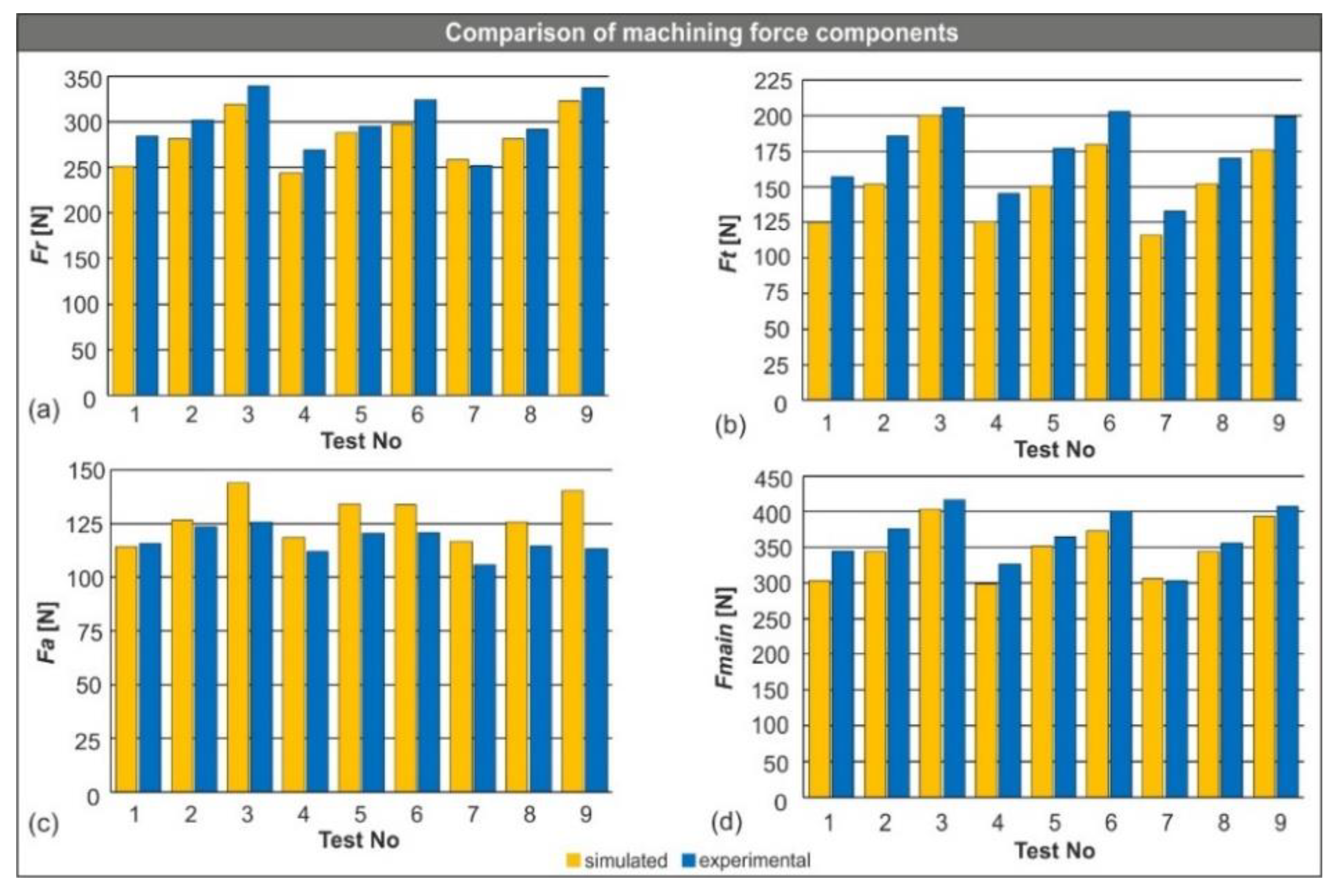
The below charts (Figure 9) were plotted to visualize all three machining force components and the resultant force. In addition, it is possible to compare the mean values of the produced cutting force components graphically. In particular, Figure 9a depicts the results for the radial force, Figure 9b for the tangential force, Figure 9c for the feed force and lastly Figure 9d for the calculated resultant force. By observing the below charts, it is concluded that the generated CAD model played a major role in the convergence of the results, despite the fact that a few discrepancies exist (mostly in the tangential and the feed force).
4. Conclusions
In the present paper, the development of a designer application with the implementation of the SolidWorks™ API under VBA coding has been presented. The purpose of the developed application is to automatically generate CAD models of cutting tools that can be used with FEA software. Upon finalizing the application, a number of simulation tests have been successfully performed to verify the functionality of the generated models.
In general, the CAD-based programming can be used to automate almost all typical design tasks, hence enhancing the design process of products and systems. Moreover, by implementing the programming tools of modern CAD systems, it is possible to develop simple applets, macros and complete applications.
As the complexity of the under study product or system increases so does the value of the developed tools, further increasing the productivity of the engineers. The presented application can become the basis for developing downstream applications by integrating FEA-based capabilities related to estimation of cutting forces and tool wear, which in general can lead to cutting condition optimization. Finally, it is safe to state the following conclusions with respect to the acquired results:
- The generated cutting tool was successfully imported to DEFORM™-3D and meshed with the maximum available number of elements.
- All the performed simulations were successfully completed within a reasonable amount of time.
- The performance of the under study cutting tool model was high, since the yielded results for the machining forces were on par with the experimental ones.
- Finally, the simulated resultant of the machining forces was in high agreement with the experimental one exceeding 90% in most cases.
Author Contributions
Conceptualization, A.T. and P.K.; methodology, A.T., C.G.-H., J.-L.H.-T. and P.K.; software, A.T.; validation, A.T.; formal analysis, A.T.; investigation, A.T.; resources, P.K.; data curation, C.G.-H., J.-L.H.-T. and P.K.; writing—original draft preparation, A.T.; writing—review and editing, A.T., C.G.-H., J.-L.H.-T. and P.K.; visualization, A.T.; supervision, C.G.-H., J.-L.H.-T. and P.K.; project administration, P.K.; funding acquisition, P.K. All authors have read and agreed to the published version of the manuscript.
Funding
This research received no external funding.
Conflicts of Interest
The authors declare no conflict of interest.
References
- Wu, Y.; Zhou, Y.; Zhou, Z.; Tang, J.; Ouyang, H. An advanced CAD/CAE integration method for the generative design of face gears. Adv. Eng. Softw. 2018, 126, 90–99. [Google Scholar] [CrossRef]
- Wang, L.; Chen, Z.C. A new CAD/CAM/CAE integration approach to predicting tool deflection of end mills. Int. J. Adv. Manuf. Technol. 2014, 72, 1677–1686. [Google Scholar] [CrossRef]
- Bartłomiej, S. Method of spiral bevel gear tooth contact analysis performed in CAD environment. Aircr. Eng. Aerosp. Technol. 2013, 85, 467–474. [Google Scholar] [CrossRef]
- Garcia-Hernandez, C.; Marín, R.; Talón, J.; Efkolidis, N.; Kyratsis, P. WEDM manufacturing method for noncircular gears using CAD/CAM software. Strojniški Vestn.-J. Mech. Eng. 2016, 62, 137–144. [Google Scholar] [CrossRef] [Green Version]
- Tzivelekis, C.; Yiotis, L.; Fountas, N.A.; Krimpenis, A. Parametrically automated 3D design and manufacturing for spiral-type free-form models in an interactive CAD/CAM environment. Int. J. Interact. Des. Manuf. 2015, 11, 223–232. [Google Scholar] [CrossRef]
- Oancea, G.; Haba, S.-A. Software Tool Used in CAPP/CAM Systems for Rotational Parts. Sci. Bull. Ser. C Fascicle Mech. Tribol. Mach. Manuf. Technol. 2016, 30, 75–78. [Google Scholar]
- Dimitriou, V.; Vidakis, N.; Antoniadis, A. Advanced computer aided design simulation of gear hobbing by means of three-dimensional kinematics modeling. J. Manuf. Sci. Eng. Trans. ASME 2007, 129, 911–918. [Google Scholar] [CrossRef] [Green Version]
- Kyratsis, P.; Bilalis, N.; Antoniadis, A. CAD-based simulations and design of experiments for determining thrust force in drilling operations. Comput. Des. 2011, 43, 1879–1890. [Google Scholar] [CrossRef]
- Ong, S.K.; Nec, A.Y.C. Automating set-up planning in machining operations. J. Mater. Process. Technol. 1997, 63, 151–156. [Google Scholar] [CrossRef]
- Harik, R.F.; Derigent, W.J.E.; Ris, G. Computer aided process planning in aircraft manufacturing. Comput. Aided. Des. Appl. 2008, 5, 953–962. [Google Scholar] [CrossRef]
- Deb, S.; Parra-castillo, J.R.; Ghosh, K. An Integrated and Intelligent Computer-Aided Process Planning Methodology for Machined Rotationally Symmetrical Parts. Int. J. Adv. Manuf. Syst. 2011, 13, 1–26. [Google Scholar]
- Kyratsis, P.; Tzotzis, A.; Tzetzis, D.; Sapidis, N. Pneumatic cylinder design using cad-based programming. Acad. J. Manuf. Eng. 2018, 16, 107–113. [Google Scholar]
- Kyratsis, P.; Tapoglou, N.; Bilalis, N.; Antoniadis, A. Thrust force prediction of twist drill tools using a 3D CAD system application programming interface. Int. J. Mach. Mach. Mater. 2011, 10, 18–33. [Google Scholar] [CrossRef] [Green Version]
- Tzotzis, A.; Garcia-Hernandez, C.; Huertas-Talon, J.-L.; Tzetzis, D.; Kyratsis, P. Engineering applications using CAD based application programming interface. MATEC Web Conf. 2017, 94, 1–7. [Google Scholar] [CrossRef] [Green Version]
- Sapidis, N.; Chatziparasidis, I. Framework to automate mechanical-system design using multiple product-models and assembly feature technology. Int. J. Prod. Lifecycle Manag. 2017, 10, 124–150. [Google Scholar] [CrossRef]
- Du, B.; Wang, X.; Feng, Y.; Yu, D.; Xu, G. Intelligent Assembly Technology Based on Standard Parts Feature of CATIA. Mod. Appl. Sci. 2014, 8, 49–55. [Google Scholar] [CrossRef] [Green Version]
- Roberto, V.; Osorio-Gómez, G. Assembly planning with automated retrieval of assembly sequences from CAD model information. Assem. Autom. 2012, 32, 347–360. [Google Scholar] [CrossRef]
- Vijayaraghavan, A.; Dornfeld, D.A. Automated Drill Modeling for Drilling Process Simulation. J. Comput. Inf. Sci. Eng. 2007, 7, 276–282. [Google Scholar] [CrossRef] [Green Version]
- Li, A.; Zhao, J.; Pei, Z.; Zhu, N. Simulation-based solid carbide end mill design and geometry optimization. Int. J. Adv. Manuf. Technol. 2014, 71, 1889–1900. [Google Scholar] [CrossRef]
- Meyer, R.; Köhler, J.; Denkena, B. Influence of the tool corner radius on the tool wear and process forces during hard turning. Int. J. Adv. Manuf. Technol. 2012, 58, 933–940. [Google Scholar] [CrossRef]
- Karpat, Y.; Ozel, T. Process simulations for 3D turning using uniform and variable microgeometry PCBN tools. Int. J. Mach. Mach. Mater. 2008, 4, 26–38. [Google Scholar] [CrossRef] [Green Version]
- Tzotzis, A.; Garcia-Hernandez, C.; Talón, J.L.H.; Kyratsis, P. Influence of the Nose Radius on the Machining Forces Induced during AISI-4140 Hard Turning: A CAD-Based and 3D FEM Approach. Micromachines 2020, 11, 798. [Google Scholar] [CrossRef]
- Denkena, B.; Lucas, A.; Bassett, E. Effects of the cutting edge microgeometry on tool wear and its thermomechanical load. CIRP Ann.-Manuf. Technol. 2011, 60, 73–76. [Google Scholar] [CrossRef]
- Denkena, B.; Koehler, J.; Rehe, M. Influence of the honed cutting edge on tool wear and surface integrity in slot milling of 42CrMo4 steel. CIRP Ann.-Manuf. Technol. 2012, 1, 190–195. [Google Scholar] [CrossRef] [Green Version]
- Vel, L.; Demazeau, G.; Etourneau, J. Cubic boron nitride: Synthesis, physicochemical properties and applications. Mater. Sci. Eng. B 1991, 10, 149–164. [Google Scholar] [CrossRef]
- Kyratsis, P. Computational design and digital manufacturing. Int. J. Mod. Manuf. Technol. 2020, 12, 82–91. [Google Scholar]
- González-Lluch, C.; Company, P.; Contero, M.; Camba, J.D.; Plumed, R. A survey on 3D CAD model quality assurance and testing tools. CAD Comput. Aided Des. 2017, 83, 64–79. [Google Scholar] [CrossRef] [Green Version]
- Tessier, S.; Wang, Y. Ontology-based feature mapping and verification between CAD systems. Adv. Eng. Inform. 2013, 27, 76–92. [Google Scholar] [CrossRef]
- Dassault Systemes; SOLIDWORKS API Help. Available online: https://help.solidworks.com/2020/English/api/sldworksapiprogguide/Welcome.htm (accessed on 17 July 2020).
- Gaitonde, V.; Karnik, S.; Figueira, L.; Davim, P. Performance comparison of conventional and wiper ceramic inserts in hard turning through artificial neural network modeling. Int. J. Adv. Manuf. Technol. 2011, 52, 101–114. [Google Scholar] [CrossRef]
- Figueira, L.; Davim, P. Machinability evaluation in hard turning of cold work tool steel (D2) with ceramic tools using statistical techniques. Mater. Des. 2007, 28, 1186–1191. [Google Scholar] [CrossRef]
- Aouici, H.; Elbah, M.; Yallese, M.A.; Fnides, B.; Meddour, I.; Benlahmidi, S. Performance comparison of wiper and conventional ceramic inserts in hard turning of AISI 4140 steel: Analysis of machining forces and flank wear. Int. J. Adv. Manuf. Technol. 2016, 87, 2221–2244. [Google Scholar] [CrossRef]
- Tzotzis, A.; Garcia-Hernandez, C.; Talón, J.L.H.; Kyratsis, P. 3D FE Modelling of Machining Forces during AISI 4140 Hard Turning. Strojniški Vestn.-J. Mech. Eng. 2020, 66, 467–478. [Google Scholar] [CrossRef]
Figure 1.
Basic geometric parameters of the SNGA120412S01525 (a), the CNGA120408T01020 (b) and the DNGA150404S01020 (c) inserts, along with their common sectioned view (d).
Figure 1.
Basic geometric parameters of the SNGA120412S01525 (a), the CNGA120408T01020 (b) and the DNGA150404S01020 (c) inserts, along with their common sectioned view (d).

Figure 2.
The micro-geometry of a typical 80° diamond-shaped insert.

Figure 3.
The application’s interface and the corresponding code keys.

Figure 4.
The application’s workflow.

Figure 5.
The design workflow for the CNGA-family inserts: (a) the construction circle, (b) the contour, (c) the extrusion, (d) the corner radius, (e) the micro-geometry and (f) the clamping hole.
Figure 5.
The design workflow for the CNGA-family inserts: (a) the construction circle, (b) the contour, (c) the extrusion, (d) the corner radius, (e) the micro-geometry and (f) the clamping hole.

Figure 6.
The shape selector algorithm flowchart.

Figure 7.
The test framework including: (a) the Finite Element (FE) model setup, (b) the force diagrams and (c) the results.
Figure 7.
The test framework including: (a) the Finite Element (FE) model setup, (b) the force diagrams and (c) the results.

Figure 8.
The model setup (a), the analysis domain (b) and the meshed tool (c).

Figure 9.
Simulated versus experimental machining force components: (a) the radial force, (b) the tangential force, (c) the feed force and (d) the resultant machining force.
Figure 9.
Simulated versus experimental machining force components: (a) the radial force, (b) the tangential force, (c) the feed force and (d) the resultant machining force.


Table 1.
API methods used for the contour creation.
| Method | Functionality | Return Value |
|---|---|---|
| ActiveDoc | Connects to the currently active document | Model document |
| NewDocument | Creates a new document using the specified template | Newly created document |
| InsertSketch | Inserts a new sketch in the current part or assembly document | − |
| CreateCircleByRadius2 | Creates a circle based on a center point and a specified radius | Newly created circle |
| CreateConstructionGeometry | Sets selected sketch segments to be construction geometry instead of sketch geometry | − |
| AddDimension2 | Creates a display dimension at the specified location for selected entities | Newly created dimension |
| CreateLine | Creates a sketch line in the currently active 2D or 3D sketch | Sketch segment for the line |
| SketchAddConstraints | Adds the specified constraint to the selected entities | − |
| FeatureExtrusion3 | Creates an extruded feature | IFeature |
Table 2.
API methods used for the topology selection.
| Method | Functionality | Return Value |
|---|---|---|
| GetBodies2 | Gets the bodies in the active part | Array of bodies |
| GetFaces | Gets all the faces on the body | Array of faces on the body |
| GetEdges | Get the edges bounding the selected face | Array of edges |
| SetEntityName | Sets the name of the entity | True/false |
| GetEntityByName | Gets an entity (face, edge, vertex) by name | Entity |
| Select4 | Selects an entity and marks it | True/false |
| FeatureFillet3 | Creates a fillet feature for selected edges and control point references | IFeature |
| InsertFeatureChamfer | Inserts a chamfer | Pointer to the IFeature object |
| FeatureCut4 | Creates a cut extrude feature | Cut extrude feature |
| SaveAs | Saves the active document to the specified name in the specified format | True/false |
Table 3.
Comparison between experimental and numerical values for the machining components.
| Cutting Conditions | Fr [N] | Ft [N] | Fa [N] | ||||||
|---|---|---|---|---|---|---|---|---|---|
| Std Order | Vc [m/min] | f [mm/rev] | ap [mm] | Exp. | FE Model | Exp. | FE Model | Exp. | FE Model |
| 1 | 80 | 0.08 | 0.30 | 251.0 | 284.2 | 125.1 | 156.8 | 114.1 | 115.7 |
| 2 | 80 | 0.11 | 0.30 | 281.6 | 302.1 | 152.1 | 185.9 | 126.6 | 123.4 |
| 3 | 80 | 0.14 | 0.30 | 319.0 | 339.6 | 200.2 | 205.7 | 144.0 | 125.6 |
| 4 | 115 | 0.08 | 0.30 | 244.3 | 269.4 | 125.3 | 145.5 | 118.4 | 112.1 |
| 5 | 115 | 0.11 | 0.30 | 287.9 | 295.3 | 150.5 | 176.8 | 134.0 | 120.5 |
| 6 | 115 | 0.14 | 0.30 | 297.6 | 324.2 | 179.9 | 202.9 | 133.6 | 120.8 |
| 7 | 150 | 0.08 | 0.30 | 258.4 | 251.7 | 116.1 | 132.7 | 116.6 | 105.9 |
| 8 | 150 | 0.11 | 0.30 | 281.4 | 291.5 | 152.5 | 169.9 | 125.5 | 114.5 |
| 9 | 150 | 0.14 | 0.30 | 323.0 | 337.0 | 176.1 | 199.3 | 140.2 | 113.2 |
Publisher’s Note: MDPI stays neutral with regard to jurisdictional claims in published maps and institutional affiliations. |
© 2020 by the authors. Licensee MDPI, Basel, Switzerland. This article is an open access article distributed under the terms and conditions of the Creative Commons Attribution (CC BY) license (http://creativecommons.org/licenses/by/4.0/).
Share and Cite
MDPI and ACS Style
Tzotzis, A.; García-Hernández, C.; Huertas-Talón, J.-L.; Kyratsis, P. CAD-Based Automated Design of FEA-Ready Cutting Tools. J. Manuf. Mater. Process. 2020, 4, 104. https://0-doi-org.brum.beds.ac.uk/10.3390/jmmp4040104
AMA Style
Tzotzis A, García-Hernández C, Huertas-Talón J-L, Kyratsis P. CAD-Based Automated Design of FEA-Ready Cutting Tools. Journal of Manufacturing and Materials Processing. 2020; 4(4):104. https://0-doi-org.brum.beds.ac.uk/10.3390/jmmp4040104
Chicago/Turabian StyleTzotzis, Anastasios, César García-Hernández, José-Luis Huertas-Talón, and Panagiotis Kyratsis. 2020. "CAD-Based Automated Design of FEA-Ready Cutting Tools" Journal of Manufacturing and Materials Processing 4, no. 4: 104. https://0-doi-org.brum.beds.ac.uk/10.3390/jmmp4040104