Probing Magnetic Pulse Welding of Thin-Walled Tubes


1
Belgian Welding Institute, Technologiepark Zwijnaarde 935, B-9052 Ghent, Belgium
2
Indian Institute of Technology, Bombay, Mumbai 400076, India
*
Author to whom correspondence should be addressed.
J. Manuf. Mater. Process. 2020, 4(4), 118; https://0-doi-org.brum.beds.ac.uk/10.3390/jmmp4040118
Submission received: 29 October 2020
/
Revised: 5 December 2020
/
Accepted: 9 December 2020
/
Published: 11 December 2020
(This article belongs to the Special Issue Impulse-Based Manufacturing Technologies)
Abstract
:Magnetic pulse welding is a solid-state joining technology, based on the use of electromagnetic forces to deform and to weld workpieces. Since no external heat sources are used during the magnetic pulse welding process, it offers important advantages for the joining of dissimilar material combinations. Although magnetic pulse welding has emerged as a novel technique to join metallic tubes, the dimensional consistency of the joint assembly due to the strong impact of the flyer tube onto the target tube and the resulting plastic deformation is a major concern. Often, an internal support inside the target tube is considered as a solution to improve the stiffness of the joint assembly. A detailed investigation of magnetic pulse welding of Cu-DHP flyer tubes and 11SMnPb30 steel target tubes is performed, with and without an internal support inside the target tubes, and using a range of experimental conditions. The influence of the key process conditions on the evolution of the joint between the tubes with progress in time has been determined using experimental investigations and numerical modelling. As the process is extremely fast, real-time monitoring of the process conditions and evolution of important responses such as impact velocity and angle, and collision velocity, which determine the formation of a metallic bond, is impossible. Therefore, an integrated approach using a computational model using a finite-element method is developed to predict the progress of the impact of the flyer onto the target, the resulting flyer impact velocity and angle, the collision velocity between the flyer and the target, and the evolution of the welded joint, which are usually impossible to measure using experimental observations.
1. Introduction
Magnetic pulse welding (MPW) is a solid-state impact welding technology able to create joints between two overlapping parts by a progressive collision, which is generated by an intense electromagnetic (EM) impulse [1]. Figure 1 shows a schematic layout for the MPW of overlapping tubes. A capacitor bank is charged by a power supply to store the required amount of energy, which is released instantaneously into a coil by using a high-current switch. The resulting discharge current of high magnitude and high frequency induces an intense transient EM field inside the coil, which induces eddy current in the outer tube [2]. The induced eddy current causes a differential EM field on both sides of the outer tube, resulting in an EM pressure that, in turn, causes the outer tube to impact onto the internal tube with high velocity [3]. As a result of the collision between the outer and the inner tubes at a certain angle, the tubes experience intense localized plastic deformation and a jet is generated along the surfaces of the materials before they make contact, which is able to remove the surface impurities and promote consolidation between the clean mating surfaces under EM pressure [2,3]. The consolidation between the two parts occurs without any bulk melting [4], although local melting at scattered locations along the joint interface is reported for MPW of AA6060 flyer tubes and copper target rods [5], AA1050 flyer and target sheets [6] and AA6060 flyer tubes and AlSi10Mg target rods [7]. For the overlapping assembly, the outer part is referred to as the flyer and the inner part is referred to as the target. Since the bulk melting of materials is avoided, MPW is increasingly considered for the joining of dissimilar materials [8].
The joining of tubular parts with MPW involves the use of a thick circular coil, with the assembly of the overlapping flyer and target tubes placed inside the coil [9]. The coil imposes a radial EM impulse pressure on the flyer tube for a very short duration, that forces the flyer to impact onto the target tube in a progressive manner, resulting in jetting of surface impurities from the original interface, a controlled plastic deformation and bonding between two tubes [10]. The welded interface in MPW is characteristically similar to that in explosion welding, which is created as a result of a traverse of collision points, followed by plastic deformation at a high strain rate and jetting out of surface impurities, and consolidation between clean metallic layers along the interface between the impacting flyer and target [5]. The phenomena of jetting due to the high velocity impact between the flyer and target and the consequent shearing of very thin layers from the metallic surfaces, the composition of the metal jets and the possible effect of jetting on the profile of the welded interface are examined by several researchers for MPW of similar and dissimilar materials [11,12,13].
Often, an internal support is employed to enhance the stiffness and avoid excessive plastic deformation and fracture of the tube assembly as a result of the high velocity impact of the flyer tube onto the target tube [14]. Especially, tubes with a small wall thickness need to be supported, because they can hardly resist radial forces. A study comparing the weld performance in terms of the contour deformation, microstructure and tensile strength of tubular joints, achieved with and without internal support, was found in [15]. An aluminium AA6060-O flyer tube (outer diameter: 76 mm × 2.5 mm) was joined onto a steel 34 (St34 mod) target tube (outer diameter: 76 mm × 2.5 mm). Other sources report the use of an internal support placed inside the target tube for MPW of AA5052 flyer tubes of wall thickness of 1 mm and SS304 target tubes of wall thickness of 1 mm [16], and for MPW of AA6060 flyer tubes of wall thickness of 1.5 mm and Cu-ETP target tubes of wall thickness of 1 mm [17]. Although these studies showed the need for an internal support during MPW of tubular parts, detailed quantitative analyses of MPW with and without an internal support are not provided.
The plastic deformation of the flyer and target tube during MPW is influenced by the nature and magnitude of the applied discharge current, the original joint configuration, the mechanical properties of the tube materials, the wall thickness of the tubes and the initial standoff distance between them, and the impact velocity of the flyer. For example, typical AA6061 flyer tubes (diameter: 40 mm × 2 mm) experienced a radial plastic deformation in the range of 1 to 2 mm during the joining with AISI1045 target rods [18]. The impact velocity of the flyer when impacting with the target rods was measured and was in the range of 245 to 305 m/s [18]. MPW of AA3003 flyer tubes (diameter: 20 mm × 1 mm) and steel target tubes (diameter: 15.2 mm × 1.7 mm) resulted in an inward plastic deformation of 1.5 mm of the joint assembly [8]. Likewise, MPW of AA6060 flyer tubes (diameter: 20 mm × 1 mm) and steel target tubes (diameter: 14.4 mm × 2.7 mm) led to an inward plastic deformation of 1.4 mm of the joint assembly [19]. An inward plastic deformation of 4.2 mm of the joint assembly was reported by Guigliemetti et al. [20] during MPW of aluminium tubes with a wall thickness of 2 mm. For MPW of Cu-DHP flyer tubes (diameter: 22.22 mm × 0.89 mm) and 11SMnPb30 steel target tubes (diameter: 16.44 mm × 2 mm), Shotri et al. [10] reported an inward deformation of approximately 5.8 mm of the joint assembly [10]. The aforementioned studies showed that the MPW of tubes would lead to an inward plastic deformation of the joining partners, and to a distortion of the final joint geometry, which may often be unacceptable and unwarranted for the intended final purpose.
A solution to restrict the inward plastic deformation of tubes during MPW when the flyer impacts on the target is to use a solid mandrel inside the target tube to enhance the stiffness of the original joint assembly. Shotri et al. [21] reported the use of a steel insert for MPW of AA2017 flyer tubes (diameter: 20 mm × 1 mm) and SS304 target tubes (diameter: 20 mm × 2 mm). Cui et al. [22] used an AA6061 supporting insert for the joining of AA5052 flyer tubes (diameter: 30 mm × 1 mm) and carbon fibre composite target tubes (diameter: 28 mm × 1.5 mm). Faes et al. [23] reported a decrease of the inward plastic deformation of the final joint assembly from 2.9 to 1 mm in MPW of Cu-DHP flyer tubes with 11SMnPb30 steel target tubes using polyurethane internal supports. The use of polyurethane internal support was also reported for MPW of AA6061 flyer tubes with a diameter of 40 mm and Cu-ETP target tubes, in order to minimize the maximum plastic deformation of the joint assembly [17]. Although these studies have showed that the use of an additional insert inside the target tube can avoid excessive plastic deformation, a detailed analysis of MPW of tubes with and without such inserts is rarely conducted.
In the present work, an effort is made to investigate the relative influence of the discharge energy, the initial standoff distance, and the use of an internal support for MPW of thin-walled Cu-DHP flyer and 11SMnPb30 steel target tubes using a bitter plate coil with a field shaper. The welded joints were produced at two different discharge energies (14 and 16 kJ), using variable standoff distances between the flyer and the target tubes, and with and without a polyurethane internal support inside the target tube. The nature of the progressive plastic deformation and evolution of the joint profile was examined in detail experimentally and using a numerical process model.
2. Materials and Methods
Figure 2 shows schematically the MPW coil, which is connected in series to an electrical discharge circuit. A five turn AA6082 bitter plate coil with a CuCrZr field shaper was used. The bitter plate coil consists of five hollow circular plates, which are made of AA6082 and held together by a set of insulated steel bolts in staggered positions. The circular coil plates with a diameter (mo) of 280 mm and a thickness (mb) equal to 12 mm have i/o (in/out) terminals at 10°, through radial cut-out sections. An insert of Cu-ETP with a thickness of 3 mm is located between the start and end of the radial sections and connects the adjacent plates (Figure 2), for a uniform circumferential flow of the discharge current. Table 1 presents the details of the discharge energy circuit and its characteristics.
A high frequency damped sinusoidal current flows through the coil when the high current switch (Sg) is activated and creates a transient EM field that induces a secondary eddy current in the inner coaxial CuCrZr field shaper. The field shaper has a tapered geometry that allows a concentrated inward flow of the surface current towards its internal face, using a radial slit across its thickness. The inner and the outer width of the field shaper are 80 and 15 mm, respectively, and its tapered angle θ is 30°. A constant initial radial gap (a) of 1.14 mm is maintained between the field shaper internal surface and the flyer tube. The process conditions, and the dimensions of the coil, field shaper and tubes assembly are presented in Table A1 (Appendix A).
A Rogowski coil was used to measure the magnitude and nature of the discharge current [10] for the applied energy of 14 and 16 kJ. A photon Doppler velocimetry (PDV) setup was used to measure the velocity of the flyer tube during the course of its acceleration, impact on the target and complete deceleration. The collimator probe of the PDV set-up has an outer diameter of 2.5 mm and is integrated into the field shaper, as shown in Figure 2. The actual arrangement of the coil and the field shaper is illustrated in Figure 3. Several bore holes and pockets were made in the field shaper in order to allow the collimator probe of the PDV set-up to access the outer surface of the flyer tube. This setup allows radial velocity measurements at the centre of the field shaper. This corresponds with a velocity measurement location at 0.5 mm from the tube extremity. The measured velocity of the flyer tube when it impacts onto the target tube is used for the comparison with the computed impact velocity of the flyer tube.
The tube assembly is comprised of a flyer tube made of the Cu-DHP alloy with a diameter (dg) equal to 22.22 mm and a wall thickness (eg) equal to 0.89 mm, and a target tube made of 11SMnPb30 steel with a wall thickness (eh) equal to 1 mm. The overlap between the flyer and the target tubes was equal to 25 mm, creating a free length of the flyer tube of 15 mm. The initial standoff distance (s) between the flyer and the target tubes was varied from 1 to 2 mm, by employing target tubes with different external diameters (dh) ranging from 18.44 to 16.44 mm.
For the purpose of minimizing the deformation of the parent part, a 50 mm-long tube made of polyurethane with an inserted solid steel bolt was used as an internal support for the target tube (Figure 4). The polyurethane had a hardness of 92 Shore A. The tubular internal supports were pre-stressed via the inserted bolt, a washer and nuts. After the MPW process, the inserts could be removed manually by releasing the bolt and could be re-used. Table 2 and Table 3 show the material properties of the coil, field shaper, flyer and target tubes, the internal polyurethane tube and the steel bolt support, respectively. These materials properties are used further in computational modelling of the MPW process in the present work.
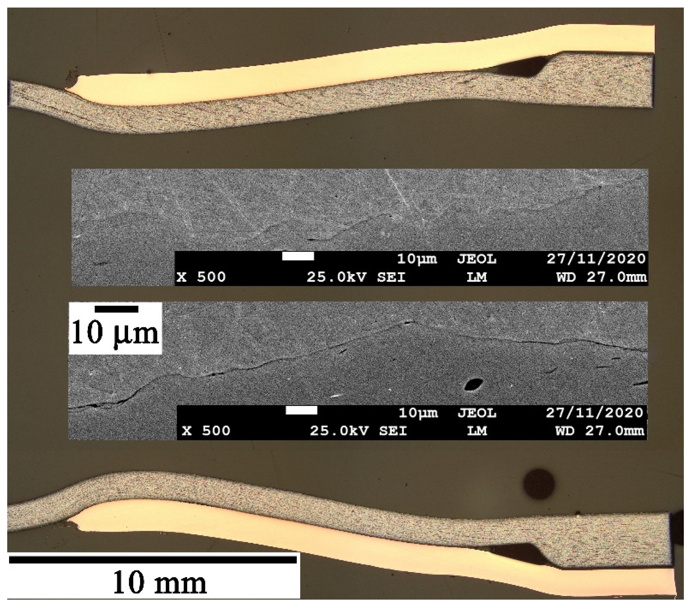
Figure 5 shows a sample welded tubular assembly, together with a typical cross-section of the joined zone. The final cross-section of each welded sample was examined along the original flyer-target overlap length, to measure the joint length and the overall deformation of the assembly. The longitudinal cross-section of each welded joint was examined using optical microscopy to obtain a macroscopic view of the entire flyer-target contact and using scanning electron microscopy (SEM) to investigate the microscopic nature of the contact interface at multiple locations. The welded length is judged based on the intimate contact along the flyer-target interface as viewed under the optical microscope. Subsequently, the microscopic nature of the interface was examined at a few locations along the welded interface using SEM. For a sample weld prepared with an internal polyurethane support, the macroscopic view of the longitudinal cross-section of the entire tubular joint and the SEM backscattered images at two random locations along the welded interface are shown together in Figure 6. Similar SEM backscattered images at six to ten locations along the welded length are examined for each welded sample to observe the interface nature. In most cases, a slightly wavy nature of the interface has been observed along the welded length, which is anticipated from the macroscopic view, based on a close scrutiny using optical microscopy.
3. Theoretical Formulation
The EM field, H, around the coil and tube assembly in the MPW process, is obtained by solving the Maxwell’s governing equation of the magnetic diffusion as [25,26]:
where, σ and µ represent the electrical conductivity and magnetic permeability. The resultant EM force, F, over the flyer tube can be estimated as:
where , B and J refer to the magnetic flux density vector and the eddy current density vector, respectively.
The dynamic impact analysis requires the application of a transient EM pressure on the flyer tube. The transient EM pressure, p, on the flyer tube is therefore estimated using the EM force, F, as,
where µ0 and µr refer to the relative magnetic permeability in the air and in the flyer tube. Hs and Hp represent the magnetic field over the surface and at a depth δ, referred to as the skin depth of the flyer tube [21]. The field intensity at a depth δ, where , is very small and hence neglected in the present analysis.
Figure 2 shows schematically the solution domain, which is considered for the EM field analysis with the density, relative permeability and electrical conductivity of air equal to 1.1614 kg/m3, 1 and zero, respectively. The solution domain is extended to 800 mm at all sides of the coil-tube assembly. The EM field remains continuous within the solution domain and is represented as [27]:
where is the unit vector normal to the surface, Js is the surface current density vector, B1 and B2 are the magnetic flux density vectors at the coil cross-sections. H1 represents the magnetic field intensity at the coil inner surface, interacting with the field shaper. H2 is the magnetic field intensity at the coil outer surface. At the domain boundary, BC2 [Figure 2], the EM field intensity becomes negligible and is represented as [27]:
The numerical model for the EM field and the mechanical analysis is undertaken using the finite-element software ANSYS (ver. 14.5). For the EM field analysis, a total of 174,000 three-dimensional tetrahedral elements were used to discretize the solution domain (Figure 2), with the current density vector as nodal input along the coil boundary and the EM field vector as the nodal degree of freedom. The estimated EM pressure distribution is employed as boundary condition for the dynamic impact analysis using a MATLAB-based code. The dynamic impact analysis includes the overlapping tubes assembly, which was discretized with 125,000 solid hexahedral elements that can consider non-linear constitutive models, which are presented in Appendix B. The computed results of the EM field and dynamic impact analyses, along with the experimentally measured results, are illustrated in the subsequent section.
4. Results and Discussions
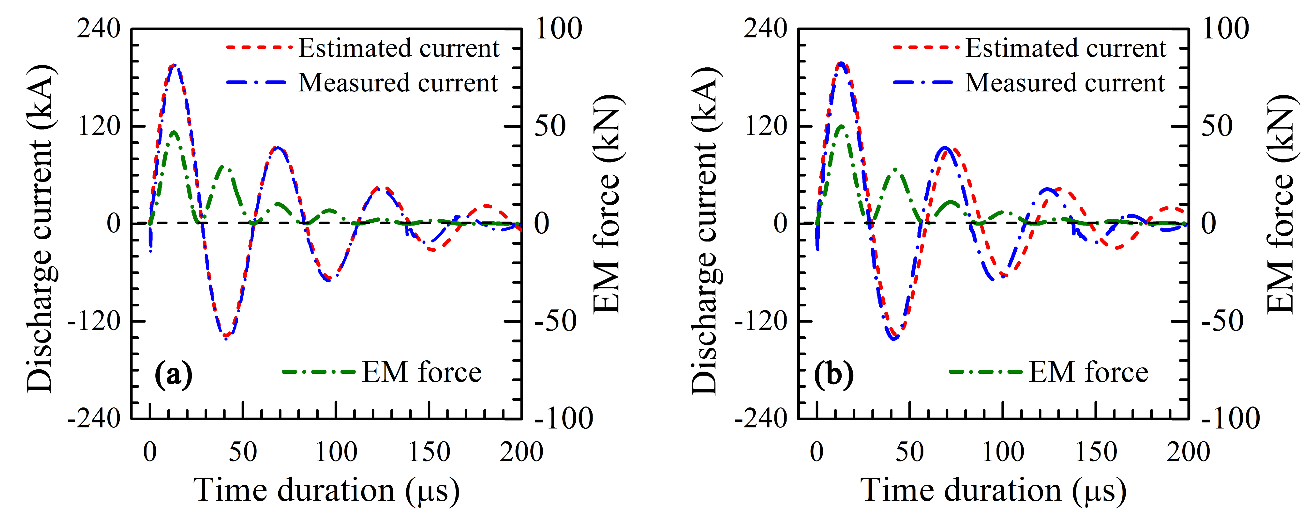
Figure 7a,b represents the measured and estimated currents for two typical values of the discharge energy of 14 and 16 kJ, which were utilized in the present work to prepare the welded samples. The peak current for a discharge energy of 14 kJ was approximately equal to 197 kA at the time instant of 13 µs. Likewise, the peak current for the discharge energy of 16 kJ was measured to be around 202 kA at the same time instant of 13 µs. The frequency of the discharge current was observed to be approximately 17 kHz. The corresponding maximum values of the EM force were calculated to be around 47.2 and 51.2 kN for a discharge energy of 14 and 16 kJ, respectively.
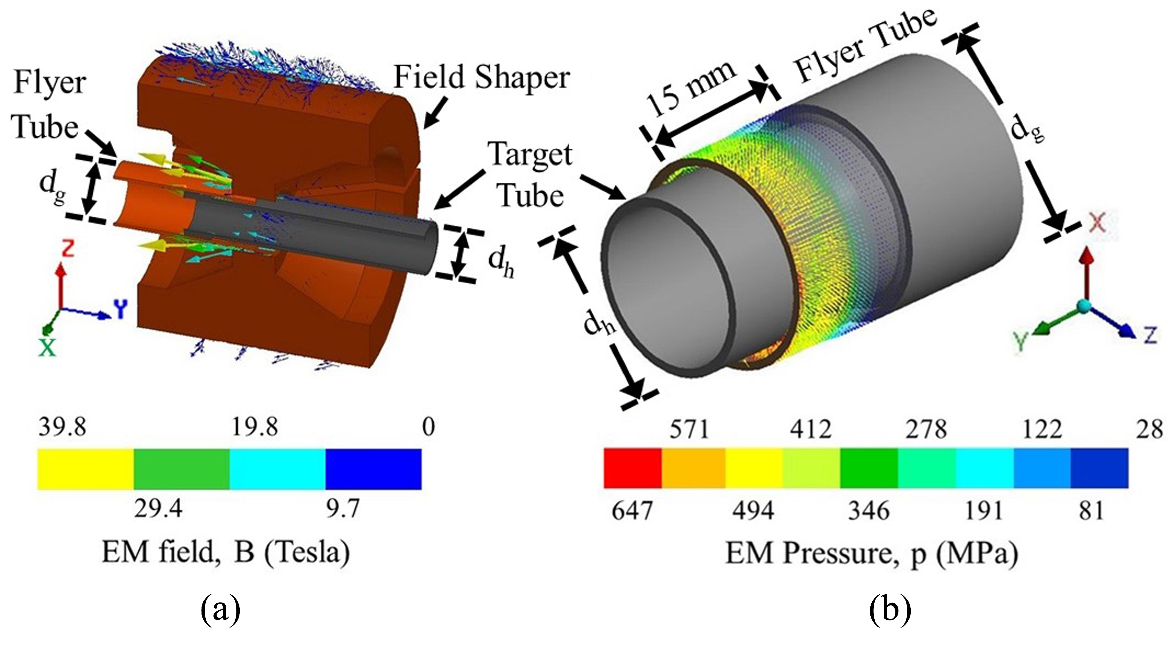
Figure 8 shows the computed results of the EM field and pressure for an applied discharge energy of 14 kJ at the time instant of 13 µs. The EM field vectors are distributed around the coil-field shaper and the flyer-target tubular assembly, as shown in Figure 8a. The EM fields are concentrated around the flyer tube portion in the proximity of the field shaper internal surface, due to its shaped geometry. The maximum values of the EM field and the eddy current density over the flyer tube surface were calculated as 39.8 T and 5.8 × 10¹⁰ A/m2 at the time instant of 13 µs.
Figure 8b shows the calculated EM pressure over the flyer tube at the time instant of 13 µs. The estimated EM pressure remains circumferentially uniform, with the maximum value equal to 647 MPa, which corresponds with the maximum EM force of 47.2 kN for the discharge energy of 14 kJ. The EM pressure on the flyer tube is maximal at its free end and decreases along its length beneath the field shaper, resulting in an inward bending and oblique impact of the flyer on the target tube. As the portion of the flyer bends and moves away from the field shaper, the EM field and pressure distribution change. This results in a progressive oblique impact of the flyer onto the target tube along their overlapping length. While Figure 8b shows the computed EM pressure distribution over the flyer tube at the time instant of 13 µs, similar EM pressure distributions are extracted for multiple discrete time-steps and used as input for the dynamic impact analysis of the tube assembly. The results of this are presented in the text below.
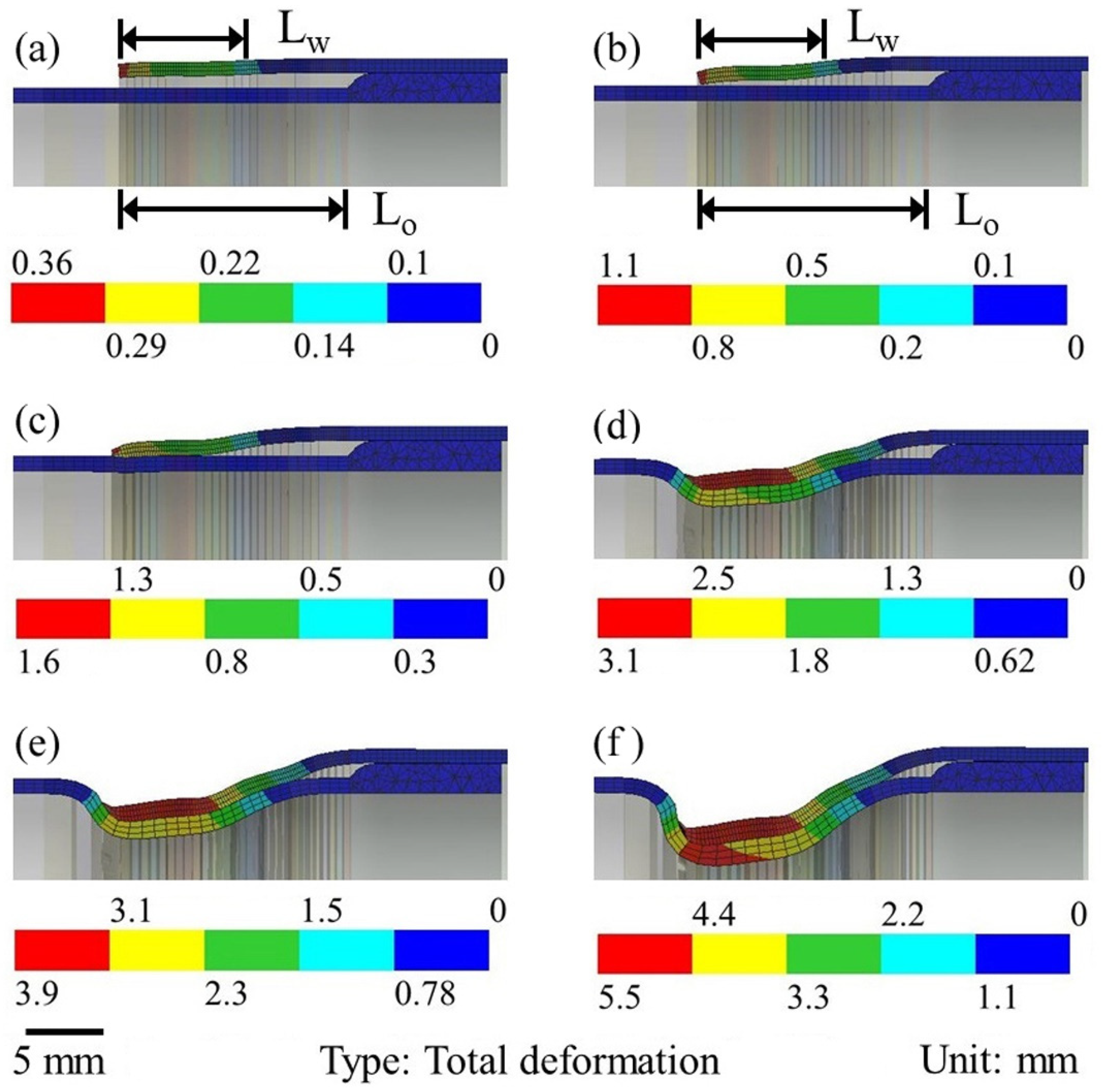
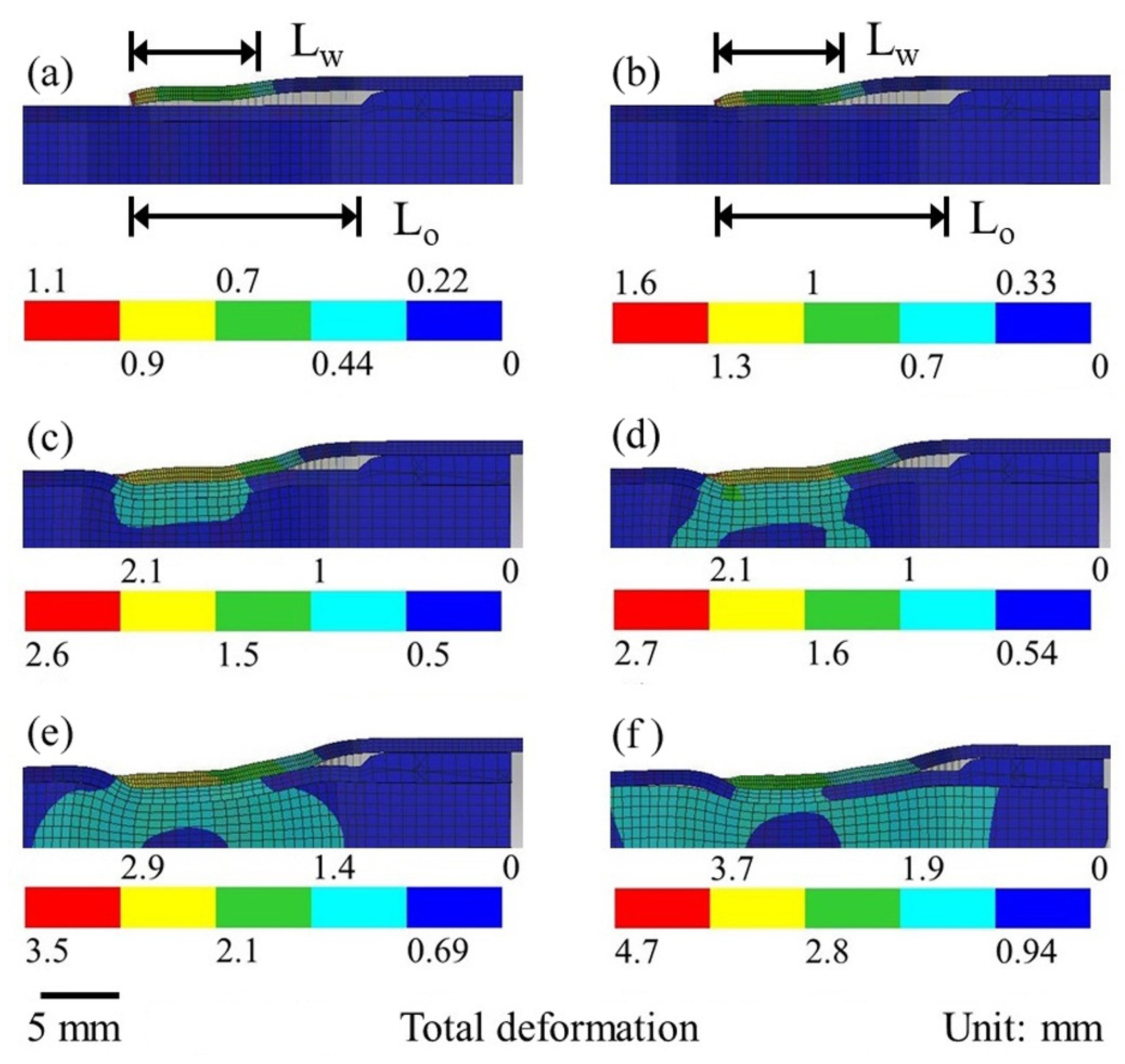
Figure 9 shows the computed results of the progressive impact and deformation of the tube assembly and, the flyer-target contact length at multiple consecutive time instants for an applied discharge energy of 14 kJ. The colour bars under each figure represent the total plastic deformation in mm, which is the resultant of the computed plastic deformations in the x-, y- and z- directions. The calculated flyer-target contact length is determined by examining the deformed portion of the flyer, which has impacted and remained in contact with the target tube under the influence of the EM pressure. The actual contact is deemed to have established for the length of the continuous segment, along which the vertical distance between the flyer and the target (i.e., the internal surface of the flyer and the outer surface of the target) tubes is equal to zero. This calculated flyer-target contact length is subsequently compared with the experimentally measured welded length.
Figure 9a shows that there is very little deformation of the flyer tube after 7 µs for a peak EM field and pressure of 33.2 T and 441 MPa. At 9 µs, the typical inward bending of the flyer can be observed, resulting in the calculated flyer-target contact length of around 1 mm for a peak EM field and pressure of 36.1 T and 520 MPa (Figure 9b). The increase of the EM field and pressure is attributed to the increase of the peak current at the time instants of 7 and 9 μs. The inward bending of the flyer continues and the calculated flyer-target contact length increases further to 8 mm at the time instant of 11 μs (Figure 9c). However, as the flyer moves away from the coil (field shaper), the peak EM field and pressure are reduced to 35.6 T and 505 MPa. With further progress in time, at 17 µs, the calculated flyer-target contact length increases to 11 mm. The inward deformation of the joint assembly also increases to 2.5 mm, while the peak EM field and pressure are reduced to 32.6 T and 430 MPa, respectively (Figure 9d).
After 21 µs, the flyer-target assembly showed an increased inward deformation of 3.1 mm, while the calculated flyer-target contact length remains the same as that at 17 µs, which is attributed to a significantly reduced peak EM field intensity and pressure of 23.3 T and 216 MPa, respectively (Figure 9e). As the time increases further, the target tube also experiences more deformation, resulting in further inward distortion of the overall tubular assembly, as shown in Figure 9f. A greater inward deformation of the tubular assembly especially at longer time durations can be attributed to the thinning of the tube walls and the consequent loss of stiffness of the tubular assembly. The computed results of the deformed tubular assembly depict a maximum thinning of both the flyer and the target tube walls by approximately 0.2 mm at the end of the flyer-target overlapping length.
The excessive inward plastic deformation of the tube assembly as shown in Figure 9f indicates that MPW of tubes can lead to a significant distortion of the tube assembly. Lueg-Althoff et al. [17] reported a similar range of plastic deformation for MPW of AA6060 flyer and AISI 1045 target tubes, with the wall thickness of the target tube equal to 1 mm. These authors suggested the use of an internal support to constrain the inward deformation of the joint assembly, while a further examination of the influence of the internal support to improve the joint profile and quality was not undertaken.
Figure 10 shows the computed results of the progressive impact and deformation of the tube assembly at multiple consecutive time instants when using a polyurethane internal support placed inside the target tube. Figure 10a confirms a calculated contact length of 1 mm between the flyer and the target tube at 9 μs. The peak EM field and pressure at 9 μs were calculated as 36.5 T and 529 MPa, respectively. After 11 μs, the calculated flyer-target contact length increases to 8.5 mm (Figure 10b) for a higher peak EM field and pressure of 37.9 T and 571 MPa, respectively. It is noteworthy in Figure 10a,b that only the flyer experiences plastic deformation and that the target tube has suffered no inward distortion. The calculated contact length between the flyer and the target tube increases further to 10.5 mm after 15 μs (Figure 10c). The computed values of the peak EM field and pressure at 15 μs showed a drop to 33.6 T and 451 MPa, respectively.
After 17 μs, the computed flyer-target contact length shows a small increase to approximately 11.5 mm (Figure 10d), and the calculated values of the peak EM field and pressure show a further drop to 32.2 T and 415 MPa, respectively. The calculated contact length between the flyer and the target shows no further increase in the subsequent time instants of 21 μs (Figure 10e) and 26 μs (Figure 10f). This is consistent with the continuing decrease of the peak EM field (~22 T) and pressure (~209 MPa) at 21 µs, as a result of the inward bending of the flyer away from the field shaper. The computed results show that the inward deformation of the tubular assembly starts late, at 15 μs (Figure 10c), and the net deformation remains very small until the end (Figure 10f), which demonstrates the role of the polyurethane internal support to enhance the stiffness of the target tube and to minimize the deformation of the tube assembly. With the internal polyurethane support inside the target tube, the computed results of the deformed tubular assembly depict a maximum thinning of the flyer tube wall by around 0.17 mm and little or no thinning of the target tube wall.
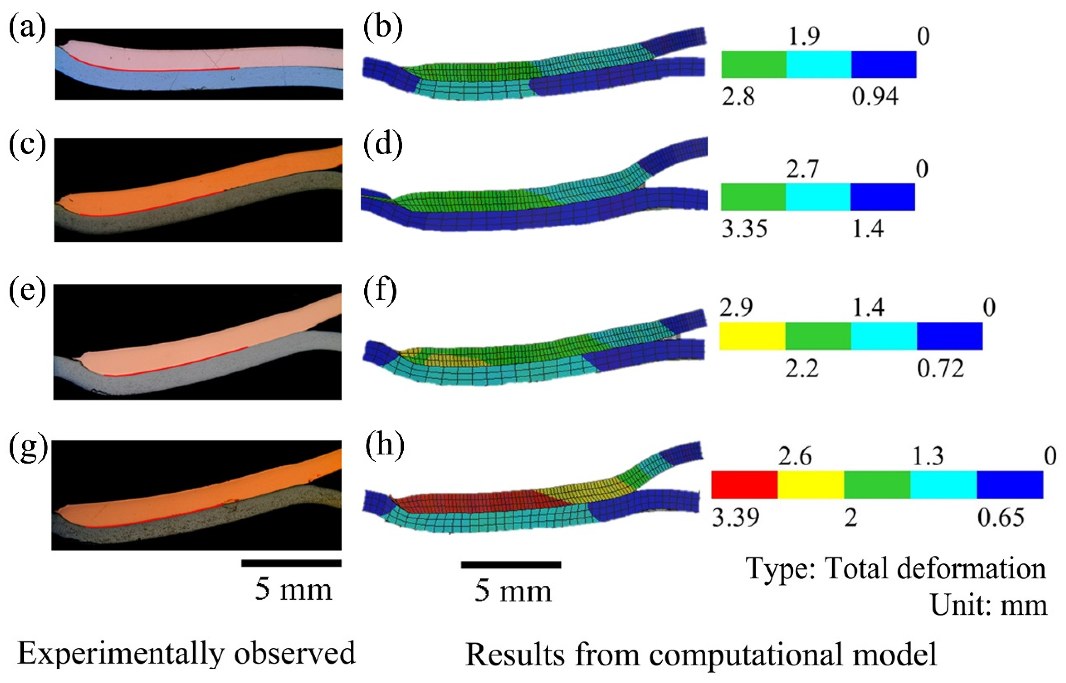
Figure 11 and Figure 12 show the longitudinal cross-section of the entire welded length and the corresponding computationally obtained flyer-target deformed profile for different process conditions. The welded length, which is judged based on the intimate contact using optical microscopy, is shown by a thin red line in the experimentally observed macroscopic sections. The microscopic view of the welded interface is also probed using SEM backscattered images at six to ten random locations along the welded length for each tubular joint, as explained earlier (Figure 6).
Figure 11 shows the experimentally observed and the corresponding computationally obtained joint cross-sections for a discharge energy of 14 and 16 kJ, and with the use of a polyurethane internal support placed inside the target tube. Figure 11a,b shows that the length of the experimentally observed welded interface and the corresponding calculated flyer-target contact length are approximately 8.3 and 11.5 mm, respectively, for a standoff distance of 1 mm and a discharge energy of 14 kJ. It is noteworthy that the calculated flyer-target contact length is obtained from the deformed interface of tubular assembly as a part of the mechanical analysis. The formation of the actual weld needs to consider the jetting of the impurities from the flyer-target interface, and localized plastic deformation creating mechanical interlock and atomic diffusion between the abutting surfaces of the flyer and the target, which are beyond the scope of the dynamic mechanical analysis adopted in the present work. As a result, the calculated flyer-target contact length remains always a little higher than the corresponding length of the experimentally observed welded interface.
As the standoff distance increases to 2 mm, both the length of the experimentally observed welded interface and the calculated flyer-target contact length decreases to 7.3 and 10 mm, respectively (Figure 11c,d). The decreasing tendency of the contact length with an increase of the standoff distance is also observed at the higher discharge energy of 16 kJ. For example, when the standoff distance increases from 1 to 2 mm at a discharge energy of 16 kJ, the length of the experimentally observed welded interface reduces from 7.3 to 6.3 mm (Figure 11e,g), and the corresponding calculated flyer-target contact lengths are around 11.5 and 10.5 mm, respectively (Figure 11f,h).
For an increasing standoff distance, the flyer tends to impact onto the target at a higher velocity and therefore the tubular assembly; in particular, the target tube suffers more plastic deformation, which impairs the progressive growth of the calculated flyer-target contact length. A comparison of Figure 11b,d clearly demonstrates the increasing deformation of the tubes when the standoff distance is increased from 1 to 2 mm at a discharge energy of 14 kJ. A similar effect of the standoff distance is also observed at the discharge energy of 16 kJ (Figure 11f,h). Overall, Figure 11 shows that an increase of the standoff distance can lead to excessive plastic deformation of the tubes and adversely affects the joint formation. The presence of an internal support inside the target and the wall thickness of the target tube also plays a significant role for restricting the deformation of the tubes.
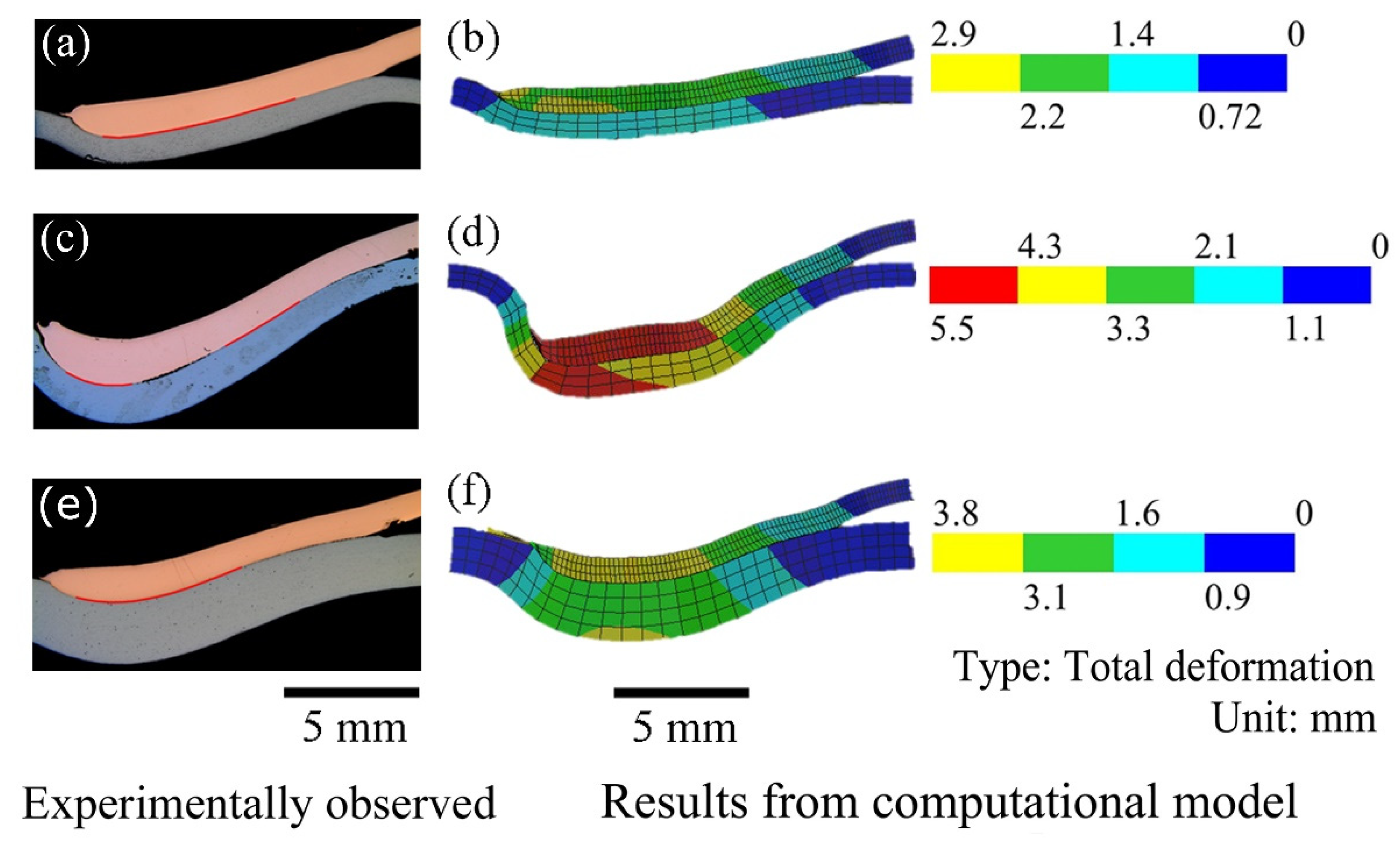
Figure 12a,b shows the experimentally observed and calculated flyer-target joint cross-sections with an internal polyurethane internal support. The length of the experimentally observed welded interface and the calculated flyer-target contact length are approximately 7.3 and 11.5 mm, respectively, for a standoff distance of 1 mm and a discharge energy of 16 kJ. The wall thickness of the target tube is 1 mm. In contrast, both the length of the experimentally observed welded interface and the calculated flyer-target contact length are reduced to approximately 5.9 and 11 mm, respectively (see Figure 12c,d), when no internal support is used inside the target tube. The reduction of the weld length is attributed to the greater plastic deformation of the tubes when no internal support is used (Figure 12b,d).
For a target tube with a wall thickness of 2 mm and without any internal support, and a discharge energy of 16 kJ, the length of the experimentally observed welded interface and the calculated flyer-target contact length are approximately equal to 6.3 and 11 mm, respectively (Figure 12e,f). A comparison of Figure 12a,b,e,f shows that the internal support has helped to produce a greater welded length even with a target tube of smaller wall thickness of 1 mm (Figure 12a,b) in comparison to that with a target tube of higher wall thickness of 2 mm (Figure 12a,b). However, a comparison of Figure 12d,f shows that the tubular assembly without any internal support suffered a greater inward deformation of 5.5 mm, with a target tube of 1 mm wall thickness in comparison to an inward deformation of 3.8 mm with a target tube of 2 mm wall thickness, which can be attributed to higher stiffness posed by the thicker target tube.
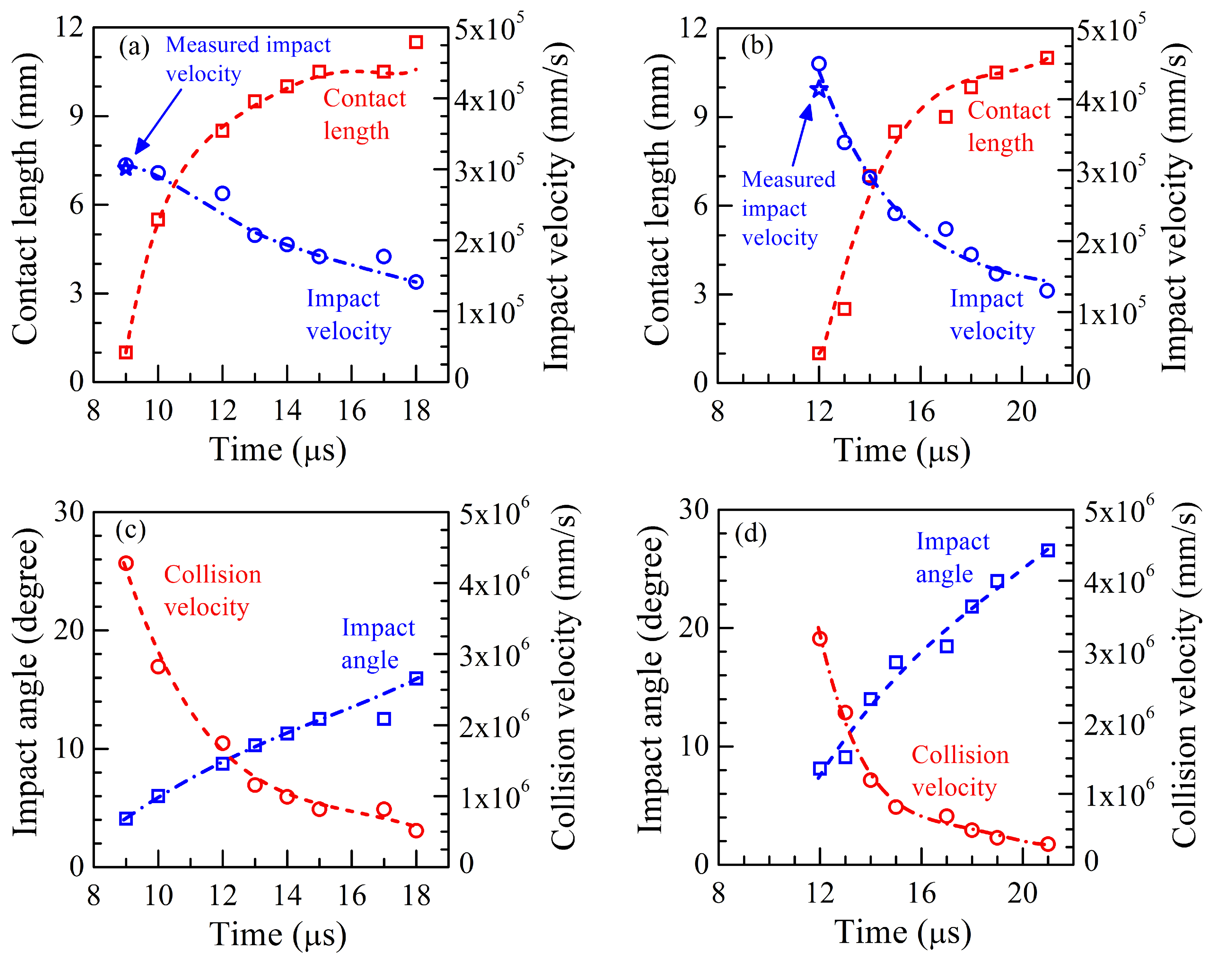
The underlying phenomena of the MPW process can be examined further by following the progress of the formation of the welded interface in accordance with the flyer impact velocity and angle, and the collision velocity between the flyer and the target. As the process is extremely fast, the real-time monitoring of the welded interface, impact velocity and angle, and the collision velocity are impossible. A computational process model is therefore a practical alternative to estimate these values. Figure 13 presents the variation of the calculated flyer-target contact length, the flyer impact velocity and angle, and the collision velocity for a discharge energy of 14 kJ and two different standoff distances. Figure 13a shows that the computed impact velocity of the flyer ranges from 3.0 × 10⁵ to 1.4 × 105 mm/s for a standoff distance of 1 mm. The corresponding experimentally measured value of the impact velocity of the flyer is around 3.1 × 105 mm/s and shown in Figure 13a. When the standoff distance is increased from 1 to 2 mm, higher values of the flyer impact velocity are obtained in the range from 4.5 × 10⁵ to 1.5 × 105 mm/s, with the corresponding measured value equal to 4.1 × 105 mm/s, as shown in Figure 13b. Figure 13a,b also shows that the growth of the calculated flyer-target contact length tends to slow down with an increase in time as the flyer impact velocity reduces.
When the flyer continues to impact onto the target in an oblique manner, knowledge of the progressive variation of the flyer impact angle is very valuable. The collision velocity is a determining factor for the occurrence of a jet which removes the surface impurities to promote the bonding between the flyer and the target. Hence, an estimation of the variation of the collision velocity and the angle is of importance. The nature of the collision velocity and its impact on the weld formation have been studied well for explosive welding, which is similar to MPW and involves the impact between flyer and target metallic parts at a certain angle. Yuan et al. [28] reported the maximum collision velocity to be around 4.9 × 10³ m/s during explosive welding of 4 mm thick AA6061 flyer sheets to magnesium alloy target plates. Bataev et al. [29] observed that the typical collision velocity of approximately 3.8 × 10³ m/s produced good joints during the explosive welding of 1 mm-thick AISI1006 flyer and target sheets, while a much higher collision velocity of around 9.6 × 10³ m/s resulted in welds with humps and excessive plastic deformation.
Figure 13c,d shows the computed results of the impact angle and collision velocity for two different standoff distances (1 and 2 mm) as the calculated flyer-target contact length increases with time. The flyer impact angle is calculated based on the deformed profile of the flyer at a certain time instant. The collision velocity is computed as Vi/sinα, where Vi is the flyer impact velocity and α is the impact angle at the end of the contact between the flyer and target [21]. For a standoff distance of 1 mm, the collision velocity and the flyer impact angle are situated in the range from 4.3 × 10⁶ to 0.5 × 106 mm/s, and from 4 to 16°, respectively (Figure 13c). For an increase of the standoff distance to 2 mm, the flyer impact angles are higher, in the range from 8 to 27°, and consequently, the collision velocity values are reduced and are in the range from 3.3 × 10⁶ to 0.3 × 106 mm/s (Figure 13d). This clearly shows that it is recommended to use a smaller initial standoff distance between the flyer and the target for the given tube dimensions and other process conditions.
For a higher discharge energy of 16 kJ, a standoff distance of 1 mm, and considering a polyurethane internal support inside the target tube, similar calculations were performed to obtain the typical ranges of the flyer impact velocity and angle, and the collision velocity. This resulted in 3.2 × 10⁵ to 1.3 × 105 mm/s, 4 to 16° and, 4.5 × 10⁶ to 0.5 × 106 mm/s, respectively. For an increase of the standoff distance to 2 mm, the calculated flyer impact velocity and angle, and the collision velocity are found to be in the range of 4.6 × 10⁵ to 2.0 × 105 mm/s, 8 to 24° and, 3.3 × 10⁶ to 0.4 × 106 mm/s, respectively. A comparison of these quantitative estimations with those presented in Figure 13a–d shows that the calculated ranges of the flyer impact velocity and angle, and the collision velocity remains almost the same for an increase of the discharge energy from 14 to 16 kJ for both standoff distances of 1 and 2 mm. However, the increase of the calculated ranges of the flyer impact velocity and angle, and the collision velocity for an increased initial standoff distance remained consistent for both values of the discharge energy 14 to 16 kJ. A further set of modelling calculations for a target tube wall thickness of 1 and 2 mm and considering the same process conditions but without a polyurethane internal support inside the target tube also provided a similar range of computed values for the flyer impact velocity and angle, and collision velocity. In other words, the polyurethane internal support inside the target has shown little effect on the computed values of EM field and force, and on the resulting range of the flyer impact velocity and angle, and the collision velocity. However, the presence of the polyurethane internal support restricted the inward deformation of the tubular assembly and preserved its dimensional consistency in all cases.
5. Conclusions
A detailed investigation of MPW of Cu-DHP flyer and 11SMnPb30 steel target tubes with and without internal supports inside the target tube is performed, using a range of experimental conditions determined by the discharge energy, the standoff distance, and the wall thickness of the target tubes. The experimental observations and the computed results show that the standoff distance between the flyer and target tubes significantly influences the progressive evolution of the impact of the flyer onto the target and the resulting growth of the weld joint between the tubes. Although a target tube with a little larger wall thickness can resist the internal deformation during impact better, the presence of an internal support is a useful tool to preserve the original dimensions of the tubular assembly. Overall, the concurrent theoretical and experimental results presented in this paper provide a useful quantitative understanding of the collision behaviour between the flyer and target tubes during MPW of tubular parts, using a typical bitter plate coil. The influence of the key processing conditions on the evolution of the welded joint between the tubes with progress in time has been determined.
Based on the experimental observations and numerical modelling of MPW of Cu-DhP flyer and 11SMnPb30 steel target tubes using a multi-turn coil assembly, the following conclusions can be formulated.
- The initial standoff distance between the flyer and the target tube plays a crucial role and has a significant influence on the progressive impact of the flyer onto the target, the collision behaviour between the tubes and the evolution of the welded interface.
- The flyer tube tends to experience significant plastic deformation as it impacts onto the target. It is necessary to use an internal support for MPW of thin-walled target tubes to avoid inward plastic deformation of the tube assembly.
- For MPW of Cu-DhP flyer and 11SMnPb30 steel target tubes with a wall thickness of 1 to 2 mm, the experimentally observed weld length ranged from 6.9 to 8.5 mm. The inward distortion of the tubular assembly could be minimized significantly by using a polyurethane internal support inside the target tube.
- The computational process model is able to predict the progress of the impact of the flyer onto the target, the resulting flyer impact velocity and angle, and the collision velocity between the flyer and target during the MPW process, which are usually impossible to measure using experimental observations. Furthermore, the computed progress of the flyer-target contact length provided a measure of the actual growth of the weld length, comparable to the reality, which cannot be measured in real-time during the MPW process. The process simulation model can therefore be considered as a valuable practical tool towards the design of the MPW process.
Author Contributions
Conceptualization, A.D. and K.F.; methodology, A.D.; software, R.S. and A.D.; validation, K.F.; investigation, R.S. and K.F.; resources, K.F. and A.D.; writing—original draft preparation, R.S.; writing—review and editing, R.S. and K.F.; visualization, R.S.; supervision, A.D.; project administration, K.F.; funding acquisition, K.F. All authors have read and agreed to the published version of the manuscript.
Funding
The present studies are funded within the project “Elektromagnetisch puls lassen van gelijksoortige en ongelijksoortige materialen—Laasbaarheid en mecanische eigenschappen” for prenormative research under the grant no. CCN/NBN/PN19A02 of the FOD Economie Belgium.
Conflicts of Interest
The authors declare no conflict of interest.
Appendix A

Table A1.
Process conditions and dimensions of coil and tubes assembly.
| Legend | Description | Unit | Value/Range |
|---|---|---|---|
| E | Discharge energy | kJ | 14, 16 |
| a | Radial gap | mm | 1.14 |
| s | Standoff distance | mm | 1, 2 |
| Lw | Overlapping length between field shaper and flyer | mm | 8 |
| L0 | Free length of flyer tube | mm | 15 |
| dg | Flyer tube diameter | mm | 22.22 |
| eg | Wall thickness of flyer tube | mm | 0.89 |
| dh | Target tube diameter | mm | 16.44 to 18.44 |
| eh | Target tube wall thickness | mm | 1, 2 |
| θ | Field shaper taper angle | degree | 30 |
| mb | Coil plate width | mm | 12 |
| mc | Coil plate concentrated section width | mm | 8 |
| mo | Plate coil diameter | mm | 280 |
| qo | Field shaper outer diameter | mm | 97.5 |
| qi | Field shaper inner diameter | mm | 24.5 |
| ql | Field shaper outer width | mm | 80 |
| qw | Field shaper inner width | mm | 15 |
Appendix B
The dynamic mechanical behaviour of the Cu-DHP flyer, the 11SMnPb30 steel target and the S235 steel bolt (used inside the polyurethane tube for internal support) is described by the following relation,
where σf, T, Tr, Tm, , and refer to the flow stress, the temperature variable, the reference temperature, the melting temperature, the equivalent plastic strain, the equivalent plastic strain rate, and the reference strain rate at Tr, respectively. The values of the materials constants A, B, C, n and m are given in Table A2. The dynamic mechanical behaviour of polyurethane is described using the Cowper–Symonds plasticity model, as follows,
The values of the materials constants A, B, n, q and for polyurethane are given in Table A2.
Table A2.
Material constants for different materials in Equations (A1) and (A2).
| Variables | Definition | Cu-DHP | 11SMnPb30 | AISI1006 | Polyurethane |
|---|---|---|---|---|---|
| A | Initial flow stress (MPa) | 90 | 350.30 | 350 | 11.05 |
| B | Hardening constant (MPa) | 292 | 325.8 | 275 | 80 |
| C | Strain rate sensitivity | 0.025 | 0.04 | 0.36 | - |
| N | Hardening exponent | 0.31 | 0.90 | 0.022 | 0.7 |
| Reference strain rate (s1) | 1.0 | 1.0 | 1.0 | 971 | |
| M | Thermal softening exponent | 1.0 | 0.30 | 1 | - |
| Tm | Melting temperature (K) | 1355 | 1673 | 1811 | |
| Q | Strain rate exponent | - | - | - | 0.98 |
Appendix C
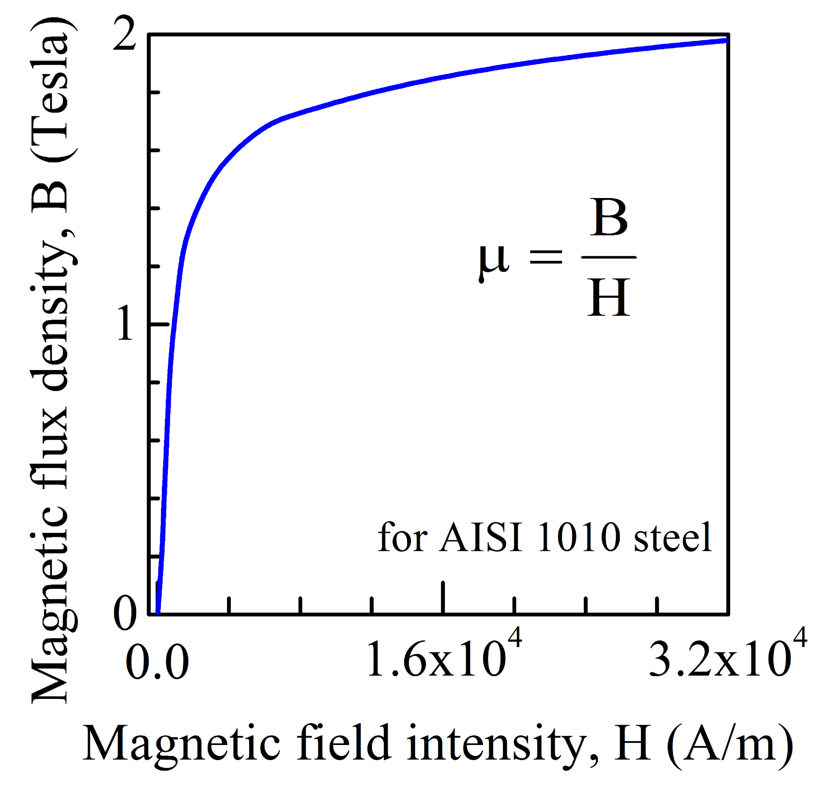
Figure A1.
B-H curve used to assign magnetic permeability of 11SMnPb30 steel.

References
- Khalil, C.; Marya, S.; Racineux, G. Magnetic pulse welding and spot welding with improved coil efficiency—Application for dissimilar welding of automotive metal alloys. J. Manuf. Mater. Process 2020, 4, 69. [Google Scholar] [CrossRef]
- Uhlmann, E.; Prasol, L.; Zilfie, A. Potentials of pulse magnetic forming and joining. Adv. Mat. Res. 2014, 907, 349–364. [Google Scholar] [CrossRef]
- Cuq-Lelandais, J.-P.; Avrillaud, G.; Ferreira, S.; Mazars, G.; Nottebaert, A.; Teilla, G.; Shribman, V. 3D impacts modeling of the magnetic pulse welding process and comparison to experimental data. In Proceedings of the 7th International Conference on High Speed Forming, Dortmund, Germany, 27–28 April 2016; pp. 13–22. [Google Scholar]
- Pourabbas, M.; Abdollah-Zadeh, A.; Sarvari, M.; Movassagh-Alanagh, F.; Pouranvari, M. Roll of collision angleduring dissimilar al/cu magnetic pulse welding. Sci. Technol. Weld. Join. 2020, 25, 549–555. [Google Scholar] [CrossRef]
- Li, J.S.; Raoelison, R.N.; Sapanathan, T.; Hou, Y.L.; Rachik, M. Interface evolution during magnetic pulse welding under extremely high strain rate collision: Mechanisms, thermomechanical kinetics and consequences. Acta Mater. 2020, 195, 404–415. [Google Scholar] [CrossRef]
- Niessen, B.; Schumacher, E.; Lueg-Althoff, J.; Bellman, J.; Bohme, M.; Bohm, S.; Tekkaya, A.E.; Beyer, E.; Leyens, C.; Wagner, M.F.-X.; et al. Interface formation during collision welding of aluminium. Metals 2020, 10, 1202. [Google Scholar] [CrossRef]
- Nahmany, M.; Shribman, V.; Levi, S.; Ashkenazi, D.; Stern, A. On additive manufactured AlSi10Mg to wrought AA6060-T6: Characterization of optimal- and high-energy magnetic pulse welding conditions. Metals 2020, 10, 1235. [Google Scholar] [CrossRef]
- Cui, J.; Sun, G.; Xu, J.; Xu, Z.; Huang, X.; Li, G. A study on the critical wall thickness of the inner tube for magnetic pulse welding of tube Al-Fe parts. J. Mater. Process. Technol. 2016, 227, 138–146. [Google Scholar] [CrossRef]
- Patra, S.; Arora, K.S.; Shome, M.; Bysakh, S. Interface characteristics and performance of magnetic pulse welded copper—Steel tubes. J. Mater. Process. Technol. 2017, 245, 278–286. [Google Scholar] [CrossRef]
- Shotri, R.; Faes, K.; De, A. Magnetic pulse welding of copper to steel tubes-Experimental investigation and process modeling. J. Manuf. Process. 2020, 58, 249–258. [Google Scholar] [CrossRef]
- Abrahamson, G.R. Permanent periodic surface deformations due to a travelling jet. J. Appl. Mech. Trans. ASME 1961, 28, 519–528. [Google Scholar] [CrossRef]
- Kakizaki, S.; Watanabe, M.; Kumai, S. Simulation and experimental analysis of metal jet emission and weld interface morphology in impact welding. Mater. Trans. 2011, 52, 1003–1008. [Google Scholar] [CrossRef] [Green Version]
- Stern, A.; Becher, O.; Nahmany, M.; Ashkenazi, D.; Shribman, V. Jet composition in magnetic pulse welding: Al-Al and Al-Mg couples. Weld. J. 2015, 94, 257s–264s. [Google Scholar]
- Grubb, S.A. Coiled Tubing Lap Welds by Magnetic Pulse Welding. US 2015/0328712 AI, 19 November 2015. [Google Scholar]
- Psyk, V.; Lieber, T.; Kurka, P.; Drossel, W.-G. Electromagnetic joining of hybrid tubes for hydroforming. Procedia CIRP 2014, 23, 1–6. [Google Scholar] [CrossRef]
- Yu, H.; Dang, H.; Qiu, Y. Interfacial microstructure of stainless steel/aluminium alloy tube lap joints fabricated via magnetic pulsed welding. J. Mater. Process. Technol. 2017, 250, 297–303. [Google Scholar] [CrossRef]
- Lueg-Althoff, L.; Bellman, J.; Hahn, M.; Schulze, S.; Gies, S.; Tekkaya, A.E.; Beyer, E. Joining of dissimilar thin-walled tubes by magnetic pulse welding. J. Mater. Process. Technol. 2020, 279, 116562. [Google Scholar] [CrossRef]
- Lueg-Althoff, J.; Lorenz, A.; Gies, S.; Schulze, S.; Weddling, C.; Goebel, G.; Tekkaya, A.E.; Beyer, E. Magnetic pulse welding by electromagnetic compression: Determination of impact velocity. Adv. Mat. Res. 2016, 966–967, 489–499. [Google Scholar] [CrossRef]
- Fan, Z.; Yu, H.; Li, C. Plastic deformation behavior of bi-metal tubes during magnetic pulse cladding: FE analysis and experiments. J. Mater. Process. Technol. 2016, 229, 230–243. [Google Scholar] [CrossRef]
- Guigliemetti, A.; Burion, N.; Marceau, D.; Rachik, M.; Volat, C. Modelling of tubes magnetic pulse welding. Conf. Eng. Syst. Des. Anal. 2012, 11, 1–12. [Google Scholar]
- Shotri, R.; Racineux, G.; De, A. Magnetic pulse welding of metallic tubes-experimental investigation and numerical modelling. Sci. Technol. Weld. Join. 2019, 25, 273–281. [Google Scholar] [CrossRef]
- Cui, J.; Li, Y.; Liu, Q.; Zhang, X.; Xu, Z.; Li, G. Joining of tubular carbon-fiber-reinforced plastic/aluminium by magnetic pulse welding. J. Mater. Process. Technol. 2019, 264, 272–282. [Google Scholar] [CrossRef]
- Faes, K.; Kwee, I.; Waele, W.D. Electromagnetic pulse welding of tubular products: Influence of process parameters and workpiece geometry on the joint characteristics and investigation of suitable support systems for the target tube. Metals 2019, 9, 514. [Google Scholar] [CrossRef] [Green Version]
- Overview of Materials for Thermoset Polyurethane, Elastomer, Unreinforced. Available online: www.matweb.com (accessed on 28 July 2020).
- Chari, M.V.K.; Salon, S.J. Numerical Method in Electromagnetic; Academic Press: San Diego, CA, USA, 2000; pp. 1–60. ISBN 0-12-615760-X. [Google Scholar]
- Sadiku, M.N.O.; Kulkarni, S.V. Principle of Electromagnetics, 6th ed.; Oxford University Press: New Delhi, India, 2015; pp. 383–480. [Google Scholar]
- NPTEL. Boundary Conditions for Electromagnetic Field, Electromagnetic Field. 2009. Available online: nptel.ac.in (accessed on 20 July 2018).
- Yuan, X.; Wang, W.; Cao, X.; Zhang, T.; Xie, R.; Liu, R. Numerical study on the interfacial behavior of Mg/Al plate in explosive/impact welding. Sci. Eng. Compos. Mater. 2017, 24, 581–590. [Google Scholar] [CrossRef]
- Bataev, I.A.; Tanaka, S.; Zhou, Q.; Lazurenko, D.V.; Jorge Junior, A.M.; Bataev, A.A.; Hokamoto, K.; Mori, A.; Chen, P. Towards better understanding of explosive welding by combination of numerical simulation and experimental study. Mater. Des. 2019, 169, 107649. [Google Scholar] [CrossRef]
- Jamil, A.; Guan, Z.W.; Cantwell, W.J.; Zhang, X.F.; Langdon, G.S.; Wang, Q.Y. Blast response of aluminium/thermoplastic polyurethane sandwich panels—Experimental work and numerical analysis. Int. J. Impact Eng. 2019, 127, 31–40. [Google Scholar] [CrossRef]
Figure 1.
Schematic layout of magnetic pulse welding (MPW) set-up for joining of tubes.

Figure 2.
Schematic representation of the coil-tube assembly and solution domain.

Figure 3.
Actual arrangement of multi-turn bitter coil and field shaper with the collimator probe (yellow) of the photon Doppler velocimetry (PDV) setup coming out of the field shaper.
Figure 3.
Actual arrangement of multi-turn bitter coil and field shaper with the collimator probe (yellow) of the photon Doppler velocimetry (PDV) setup coming out of the field shaper.

Figure 4.
Schematic representation of the tubular internal support used in the experiments with flyer tube diameter dg = 22.22 mm and target tube diameter dh = 16.44 to 18.44 mm.
Figure 4.
Schematic representation of the tubular internal support used in the experiments with flyer tube diameter dg = 22.22 mm and target tube diameter dh = 16.44 to 18.44 mm.

Figure 5.
(a) Typical welded assembly and (b) cross-section in the as-welded condition with flyer tube diameter dg = 22.22 mm and target tube diameter dh = 16.44 to 18.44 mm.
Figure 5.
(a) Typical welded assembly and (b) cross-section in the as-welded condition with flyer tube diameter dg = 22.22 mm and target tube diameter dh = 16.44 to 18.44 mm.

Figure 6.
Macroscopic view of the longitudinal joint cross-section with SEM backscattered images at two random locations along the welded length, showing a slightly wavy interface profile for a weld made with a polyurethane internal support. Conditions for this welded sample: discharge energy = 14 kJ, standoff distance = 1 mm, flyer tube diameter and wall thickness = 22.22 and 0.89 mm, target tube diameter and wall thickness = 18.44 and 1 mm.

Figure 7.
Experimentally measured and analytically estimated nature of the discharge current, and numerically computed EM force for an applied energy of (a) 14 kJ and (b) 16 kJ.
Figure 7.
Experimentally measured and analytically estimated nature of the discharge current, and numerically computed EM force for an applied energy of (a) 14 kJ and (b) 16 kJ.

Figure 8.
Numerically computed distribution of the maximum (a) EM field over the field shaper-tube assembly, and (b) EM pressure over the flyer tube for an applied energy of 14 kJ.
Figure 8.
Numerically computed distribution of the maximum (a) EM field over the field shaper-tube assembly, and (b) EM pressure over the flyer tube for an applied energy of 14 kJ.

Figure 9.
Computed results of the progressive impact and plastic deformation of the tube assembly at the time instants of (a) 7 µs, (b) 9 µs, (c) 11 µs, (d) 17 µs, (e) 21 µs and (f) 26 µs for a discharge energy of 14 kJ and with no internal support inside the target tube. (Initial conditions: wall thicknesses of flyer = 0.89 mm and of target = 1 mm; standoff distance between flyer and target = 1 mm; overlapping length between field shaper and flyer, Lw = 8 mm and free length of the flyer tube, Lo = 15 mm).

Figure 10.
Computed results of the progressive impact and plastic deformation of the tube assembly at the time instants of (a) 9 µs, (b) 11 µs, (c) 15 µs, (d) 17 µs, (e) 21 µs and (f) 26 µs for an applied discharge energy of 14 kJ and with a polyurethane internal support for the target tube. (Initial conditions: wall thicknesses of the flyer = 0.89 mm and of the target = 1 mm; standoff distance between the flyer and the target = 1 mm; overlapping width between the field shaper and the flyer, Lw = 8 mm and free length of the flyer tube, Lo = 15 mm).

Figure 11.
Experimentally observed and computationally evaluated flyer-target joint cross-sections for a discharge energy of 14 kJ (a–d) and 16 kJ (e–h), with a polyurethane internal support inside the target tube. (Initial conditions: flyer-target standoff distance = 1 mm (a,b,e,f) and 2 mm (c,d,g,h); flyer tube: diameter = 22.22 mm, wall thicknesses = 0.89 mm; target tube: wall thicknesses = 1 mm; diameter = 18.44 mm (standoff distance = 1 mm), 16.44 mm (standoff distance = 2 mm)).

Figure 12.
Experimentally observed and computationally estimated flyer-target joint cross-sections with a polyurethane internal support (a,b), and without any internal support (c–f) for the target tube. (Initial conditions: discharge energy: 16 kJ (a,b,e,f), 14 kJ (c,d); flyer: diameter = 22.22 mm, wall thicknesses = 0.89 mm; and target: diameter = 18.44 mm, wall thicknesses = 1 mm (a–d), 2 mm (e,f); standoff distance = 1 mm).

Figure 13.
Computed values of the flyer-target contact length, the flyer impact velocity and angle and the collision velocity as a function of time, for an applied discharge energy of 14 kJ with a polyurethane internal support of the target tube. (Initial conditions: flyer: diameter = 22.22 mm, wall thicknesses = 0.89 mm; and target: diameter = 18.44 mm, wall thicknesses = 1 mm; standoff distance between the flyer and the target = 1 mm (a,c) and 2 mm (b,d)).

Table 1.
Details of discharge circuit elements and energy characteristics.
| Discharge circuit | Capacitance (µF) | Resistance (mΩ) | Inductance (µH) |
| C = 160 | R = 14.3 | L = 0.55 | |
| Generator capacity | E = 50 kJ, U = 25 kV | ||
| Characteristics of the discharge energy | |||
| Pulse frequency | = 106.76 × 10³ rad/s | ||
| Damping coefficient | = 7.69 × 10⁵ s | ||
| Discharge current | , where | ||
Table 2.
Material properties of coil, field shaper and tubes (flyer-target) [10].
Table 2.
Material properties of coil, field shaper and tubes (flyer-target) [10].
| Property | Symbol | Coil AA6082 | Field Shaper CuCrZr | Flyer Cu-DHP | Target 11SMnPb30 |
|---|---|---|---|---|---|
| Relative permeability | μ | 1 | 0.99 | 0.99 | B-H curve * |
| Electrical conductivity (S/m) | σ | 26.32 × 10⁶ | 58 × 106 | 46.9 × 10⁶ | 5.75 × 10⁶ |
| Density (kg/m3) | ρ | 2700 | 8933 | 8900 | 7800 |
| Specific heat (J/kg/K) | cp | 900 | 385 | 386 | 472 |
| Shear modulus (GPa) | G | 26.3 | 45 | 47.8 | 129 |
| Poisson ratio | ν | 0.33 | 0.38 | 0.38 | 0.29 |
* B-H curve for 11SMnPb30 steel is presented as Figure A1 in Appendix C.
Publisher’s Note: MDPI stays neutral with regard to jurisdictional claims in published maps and institutional affiliations. |
© 2020 by the authors. Licensee MDPI, Basel, Switzerland. This article is an open access article distributed under the terms and conditions of the Creative Commons Attribution (CC BY) license (http://creativecommons.org/licenses/by/4.0/).
Share and Cite
MDPI and ACS Style
Faes, K.; Shotri, R.; De, A. Probing Magnetic Pulse Welding of Thin-Walled Tubes. J. Manuf. Mater. Process. 2020, 4, 118. https://0-doi-org.brum.beds.ac.uk/10.3390/jmmp4040118
AMA Style
Faes K, Shotri R, De A. Probing Magnetic Pulse Welding of Thin-Walled Tubes. Journal of Manufacturing and Materials Processing. 2020; 4(4):118. https://0-doi-org.brum.beds.ac.uk/10.3390/jmmp4040118
Chicago/Turabian StyleFaes, Koen, Rishabh Shotri, and Amitava De. 2020. "Probing Magnetic Pulse Welding of Thin-Walled Tubes" Journal of Manufacturing and Materials Processing 4, no. 4: 118. https://0-doi-org.brum.beds.ac.uk/10.3390/jmmp4040118