Article

Difficult Cutting Property of NiTi Alloy and Its Mechanism

1
Graduate School of Science and Technology, Shizuoka University, 3-5-1 Johoku Naka-ku, Hamamatsu 432-8561, Japan
2
National Institute of Technology, Numazu College, 3600 Ooka Numazu, Shizuoka 410-8501, Japan
*
Author to whom correspondence should be addressed.
J. Manuf. Mater. Process. 2020, 4(4), 124; https://0-doi-org.brum.beds.ac.uk/10.3390/jmmp4040124
Submission received: 20 November 2020 / Revised: 15 December 2020 / Accepted: 17 December 2020 / Published: 18 December 2020
(This article belongs to the Special Issue Progress in Precision Machining)

Abstract

:
This paper describes the difficult machinability of nickel titanium alloy (NiTi alloy) and its mechanism. As a result of examining the difficult cutting machinability via a turning experiment, NiTi alloy cutting showed larger cutting force, higher cutting temperature, and severe tool wear with plastic deformation of the tool compared to Ti-6Al-4V. In addition, the discharged chips were tangled with the jaw chuck and the cutting tool. As a result of investigating the cause of these difficult machining properties by orthogonal cutting, it was found that the progression of severe flank wear is affected by the elastic recovery due to the super elasticity of the material. The verification of the results according to the shear plane theory suggest that the large deformation resistance of the material is the cause of the increase in cutting temperature. Furthermore, because the cutting temperature exceeds the shape memory transformation temperature, the generated chips are shape memory processed. It was also found that because the generated chips are super elastic, chips are not easily broken and they are lengthened, and are easily entangled with a cutting tool and a jaw chuck.

1. Introduction

Nickel titanium alloy (NiTi alloy), an alloy comprising approximately 50% each of nickel (Ni) and titanium (Ti), has unique properties, such as the shape memory effect and super elasticity; therefore, it is generally known as a shape memory alloy. Although there are other copper- and iron-based shape memory alloys, NiTi alloy has superior corrosion resistance [1], biocompatibility, and high fatigue strength compared with other alloys [2]. In the future, further industrial application of NiTi is expected. A number of products utilize the super elasticity and shape memory effect of NiTi alloy, such as frames of glasses, cellular phone antennas, medical stents, and industrial actuators [3,4]. Because these products are generally manufactured by rolling and drawing after casting, they are usually in the shape of a thin wire. In recent years, in the medical field, the demand for stents, catheters, and tube parts that utilize the abovementioned properties of NiTi alloy have increased [5]. These parts are required to have highly precise finishes and dimensions. Because the cost of materials for NiTi alloy is extremely high, the development of a high-precision, cost-efficient processing method is desired from the perspective of product distribution. Cutting is a possible solution due to its high degree of freedom during the formation of the products’ shapes with superior productivity and processing precision. For example, fine hollow shapes such as stents and catheters are produced through drawing, but cutting is applied to drilling and the peripheral processing before drawing. However, it has been only 60 years since NiTi alloy was developed and only about 30 years since it was first put to practical use [6]. Therefore, cutting methods for NiTi have not yet been established. Mori et al. [7] and Wu et al. [8] reported on the cutting properties of NiTi alloy, stating that tool wear is severe with an excessive generation of burrs, the material is extremely difficult to cut, and changes in cutting conditions do not improve the cutting properties. Regarding the tool wear of cutting of NiTi alloy, Kaynak et al. performed a turning experiment using a carbide tool (group K) and reported that at a cutting speed of v = 100 m/min (feed rate of f = 0.05 mm/rev, depth of cut of t = 0.5 mm), boundary wear of approximately 300 µm was shown in a cutting time of 7.5 s. At this time, even if the cutting speed was reduced to v = 200 m/min under the same cutting conditions, the boundary wear was 250 µm with a cutting time of 15 s [9]. Kaya et al. performed cutting experiments of NiTi alloy using PCD (Poly crystalline Diamond) tools and reported that flank wear of 300 µm was observed at a cutting distance of 120 m (v = 70 m/min, f = 0.5 mm/rev, t = 0.2 mm) [10]. Altas et al. reported that in face milling of NiTi alloy using carbide tools, even at a low cutting speed of 20 m/min, flank wear was 600 µm at a cutting distance of 100 m [11]. Weinert et al. [12,13,14] also reported that although the use of coated tools is effective in reducing the cutting force, it does not reduce tool wear. In addition, they also reported that the use of cutting fluid is effective in reducing the cutting force and tool wear. In the medical field, for example, a cleaning process is essential when a cutting fluid is used. However, because NiTi alloy requires an extremely complex cleaning process, the use of a coolant is not desirable. Furthermore, several reports have been published on the machining difficulty of NiTi alloy, but no reports exist that discuss the relationship between the characteristics of NiTi alloy (super elasticity and shape memory effect) and its cutting properties, which is suspected to be the cause of such difficulty. Super elasticity and the shape memory effect are based on the phase transformation of the alloy, and only the study by Kaynak et al. has focused on this aspect [15,16,17,18,19,20,21]. They used liquid nitrogen to cool the material from the austenitic to the martensitic state before cutting and found an improvement in cutting properties. Because their experiment was conducted in a unique environment with an extremely cold temperature, the cutting phenomenon at room temperature would likely be quite different. Nevertheless, their study indicated that phase transformation and material temperatures have an impact on the cutting properties of NiTi alloy, which is an extremely important finding. Therefore, to improve cutting properties of NiTi alloy, the influence of super elasticity and shape memory effect, which are unique phenomena of NiTi alloy that are derived from the phase transformation, must be elucidated. Yet, most existing studies relate to the optimization of cutting conditions.
In this study, cutting properties of NiTi alloy, including cutting forces, cutting temperature, and tool wear, were measured during turning experiments. Furthermore, orthogonal cutting experiments were conducted. Cutting ratio, shear angle, shear stress, and coefficient of friction were calculated, and the effect of super elasticity on the cutting difficulty was investigated. In addition, cutting chips were analyzed using X-ray diffraction (XRD) and chip formation was observed using a high-speed camera to investigate the shape memory effect on the cutting difficulty.

2. Experimental Procedure

2.1. Material Properties

The NiTi alloy used for the experiment was 56Ni-44Ti (wt%) obtained from Furukawa Techno Material Co., Ltd. (Hiratsuka, Japan). The diameter of the workpiece was 80 mm. Its stabilized phase at room temperature is an austenitic phase. The phase transformation from austenite to martensite occurs at −23.6 °C (Ms: Martensite start) to −41.2 °C (Mf: Martensite finish) during cooling. When heating, the phase transformation from martensite back to austenite occurs at −17.9 °C (As: Austenite start) to −2.5 °C (Af: Austenite finish).

2.2. Cutting Conditions

In this study, an outer turning experiment was performed to investigate the cutting characteristics of NiTi alloy, and orthogonal cutting was performed to investigate the cause of the difficult cutting properties of this alloy. All experiments were conducted using a general-purpose lathe under dry conditions.
As shown in Figure 1 (left), the turning experiment was performed with the cutting conditions shown in Table 1 using non-coated carbide tools (TNGG160404, K10, Tungaloy Corp, Iwaki, Japan). For NiTi alloy, the cutting speed was set at 25–100 m/min based on the recommended cutting speed for a typical Ni alloy (V = 15–30 m/min) and a typical Ti-6Al-4V (V = 35–80 m/min). For comparison, 6Al-4V titanium alloy (Ti-6Al-4V), which is also known as a material which is difficult to cut, was additionally studied.
In an orthogonal cutting experiment, a disc-shaped workpiece with a thickness of 2 mm was cut in the radial direction as shown in Figure 1 (right). The cutting tools used for this experiment were non-coated carbide (TNGG160404, K10, Mitsubishi Materials Corp.) without a chip breaker. Stainless steel (ISO: X5CrNi18-10) with similar thermal conductivity and specific heat to those of NiTi was used for comparison to examine the influence of thermal wear. The feed was set at 0.1 mm/rev, and the cutting was performed while changing the cutting speed. Orthogonal cutting was performed with the cutting conditions shown in Table 1.

2.3. Experimental Measurements

In the turning and orthogonal cutting experiments, the cutting force was measured using a dynamometer (Kistler 9272). The cutting force was recorded using data acquisition software (Kistler, DynoWare). The cutting force was measured three times under each condition, and the average value was calculated. The tool wear test was performed once under each cutting condition.
In the orthogonal cutting experiment, cutting ratio, shear angle, friction coefficient, etc., were calculated from the measured cutting force (Fc), thrust force (Ft), and chip thickness (t2) using shear surface theory [22], as shown in Figure 2, in which: R is the force between the tool face and the chip, R′ is the force between the workpiece and the chip along the shear plane, Fs is the force component parallel to the shear plane, Fn is the force component normal to Fs. In the shear surface theory, as the cutting tool is forced into the work material, the chip is formed by shear deformation along the shear plane, which is oriented at an angle φ with the work material. The ratio of t1 to t2 is known as the cutting ratio, rc, which can be calculated by Equation (1):
r c = t 1 t 2
where rc is the cutting ratio, t1 is the nominal thickness of the cut, t2 is the chip thickness. This equation can be solved for φ as Equation (2):
t a n = r c c o s α 1 r c s i n α
where φ is the shear angle, α is the rake angle. The area of the shear plane (As) can be determined by Equation (3):
A s = t 1 b s i n
where b is the width of the cut. Thus, the shear stress in the shear plane and normal stress in the shear plane are described by Equations (4) and (5):
τ s = ( F c c o s F t s i n ) s i n t 1 b
σ s = ( F c s i n + F t c o s ) s i n t 1 b
where τs is the shear stress in shear plane, σs is the normal stress in shear plane. μ is the coefficient of friction at the interface between the chip and the tool, then F and N are related as Equation (6),
μ = F N = F c t a n α + F t F c F t t a n α
where F is the force component parallel to the tool rake face (friction force) and N is the force component normal to F.
Furthermore, in this study, the tool–work thermocouple method was used to measure the cutting temperature, and the temperature was also measured from the calibrated value obtained through a separate experiment. Chip formation was observed by a high-speed camera (HAS-D71, DITECT Co., Ltd., Tokyo, Japan) in the orthogonal cutting experiment.

3. Result and Discussion

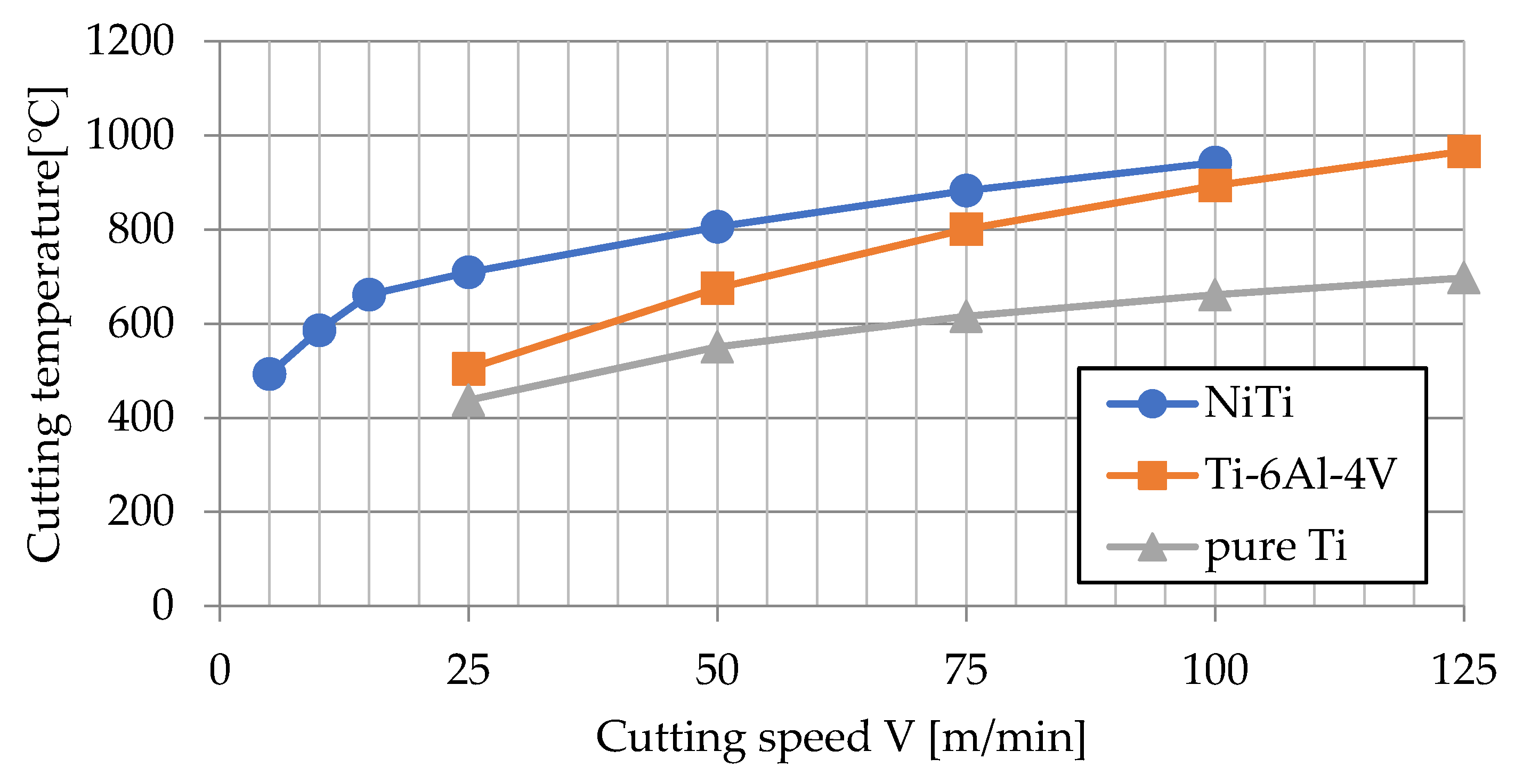
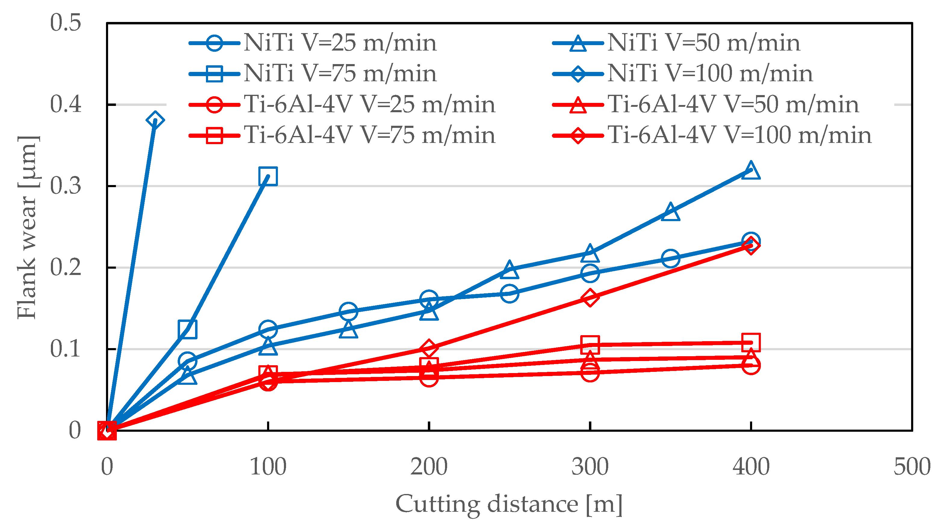
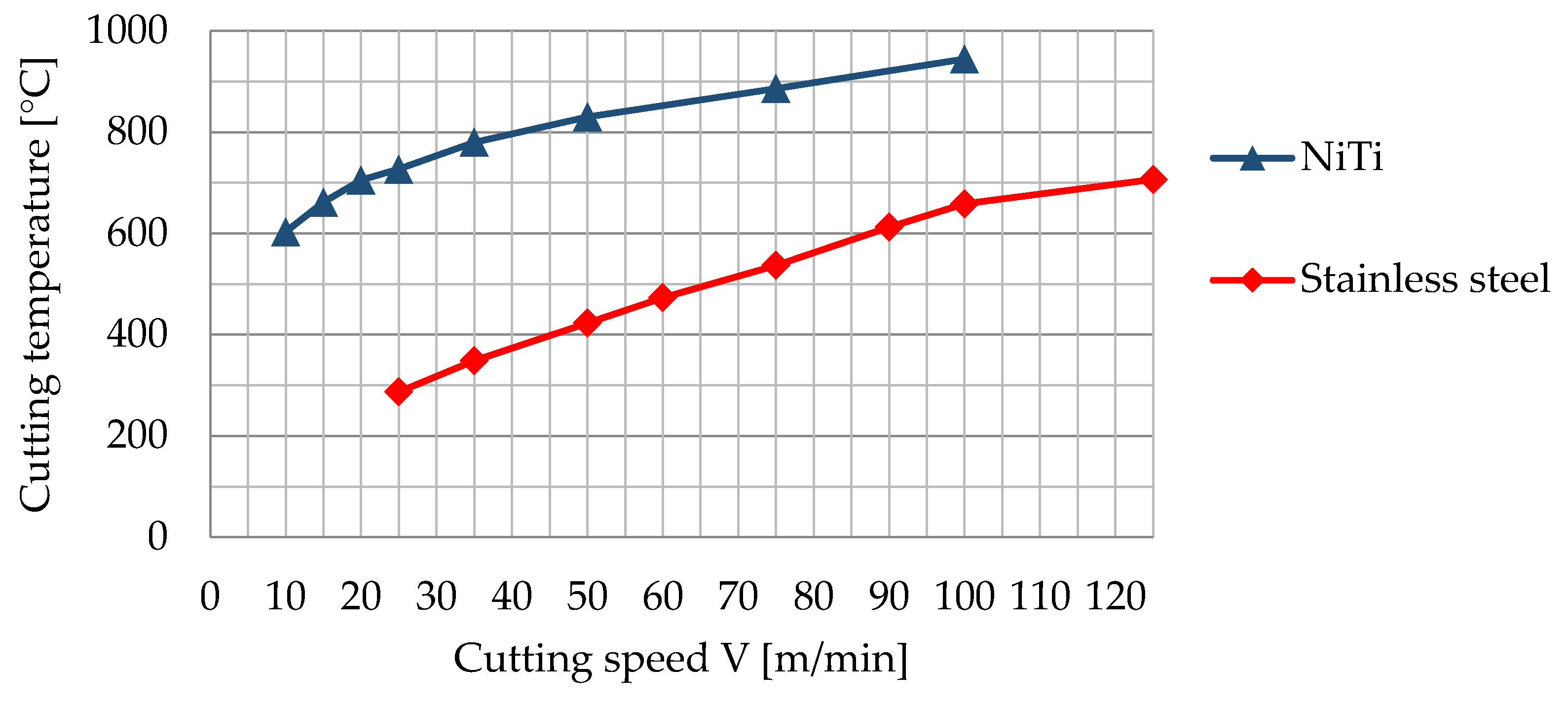
3.1. Cutting Characteristics and Difficult to Cut Property of NiTi Alloy

The turning experiment was performed to examine the cutting properties of NiTi alloy. Figure 3 shows the cutting temperature obtained by the tool–work thermocouple method. The figure shows that the cutting temperature of NiTi alloy is approximately 250 °C higher than that of pure Ti. When cutting at a speed of 25 m/min, the cutting temperature of NiTi alloy is 200 °C higher than that of Ti-6Al-4V. In particular, the difference is higher at lower cutting speeds. When cutting NiTi alloy, even at very low speeds of 5 m/min, the cutting temperature is still reasonably high (ca. 500 °C).
Figure 4 shows the measurement results of the cutting force. The figure shows that the cutting force for NiTi alloy is twice as large as that for Ti-6Al-4V. Figure 5 shows the observation results of cutting tools. When cutting NiTi, there was a notable plastic deformation of tools at the cutting distance of 100 m with a cutting speed of 75 m/min and at the cutting distance of 30 m with the cutting speed of 100 m/min, which made continuation of the cutting process impossible. Compared with Ti-6Al-4V, NiTi alloy presents severe flank and face wear, as shown in Figure 6. In addition, the cutting of NiTi alloy is characterized by notable boundary wear, which is not observed in cutting Ti-6Al-4V. Generally, the characteristic wear for cutting a Ti-6Al-4V is face wear, whereas that for cutting an Ni alloy such as Inconel is boundary wear [23,24]. However, the cutting of NiTi alloy shows both of these characteristics.

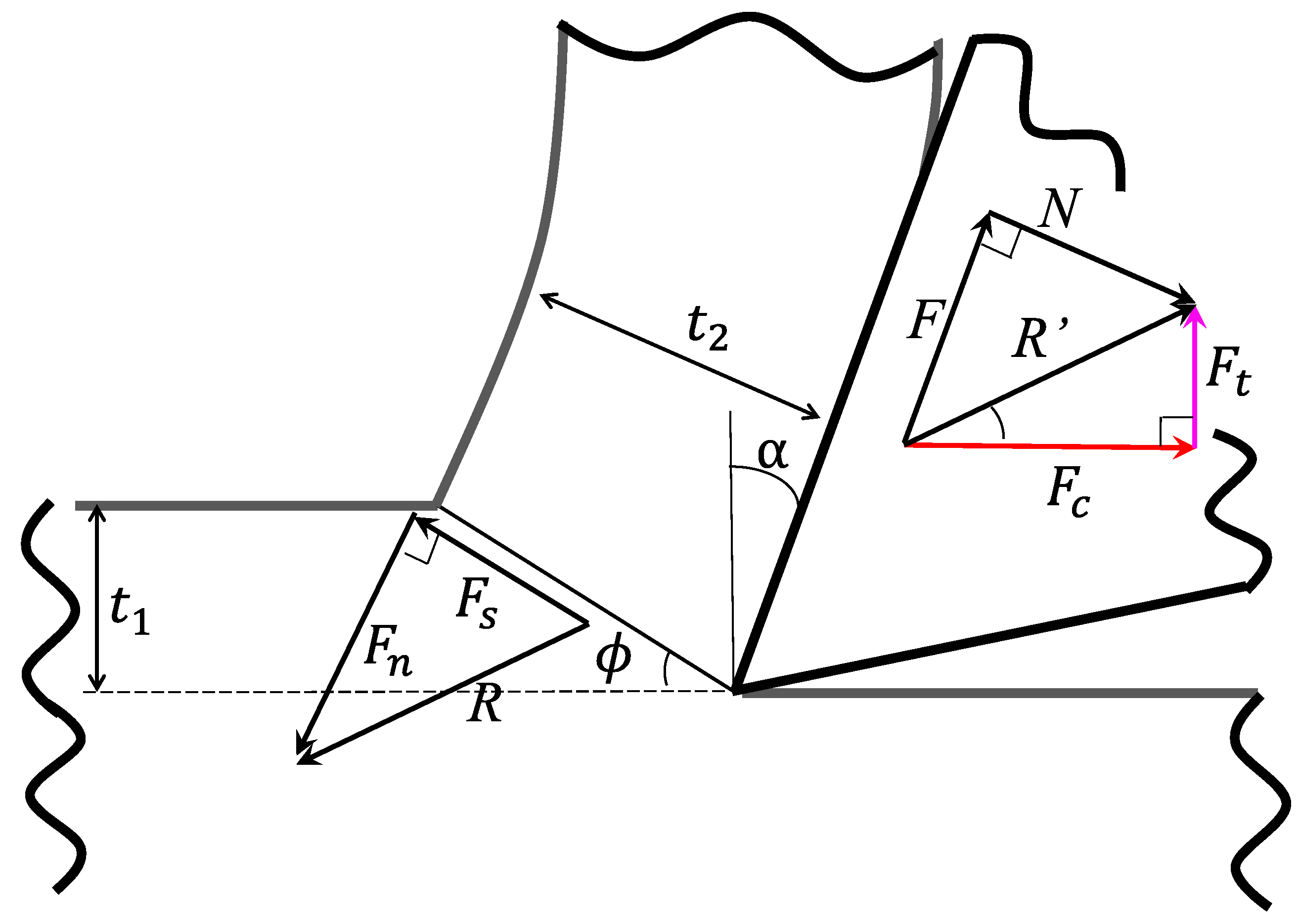
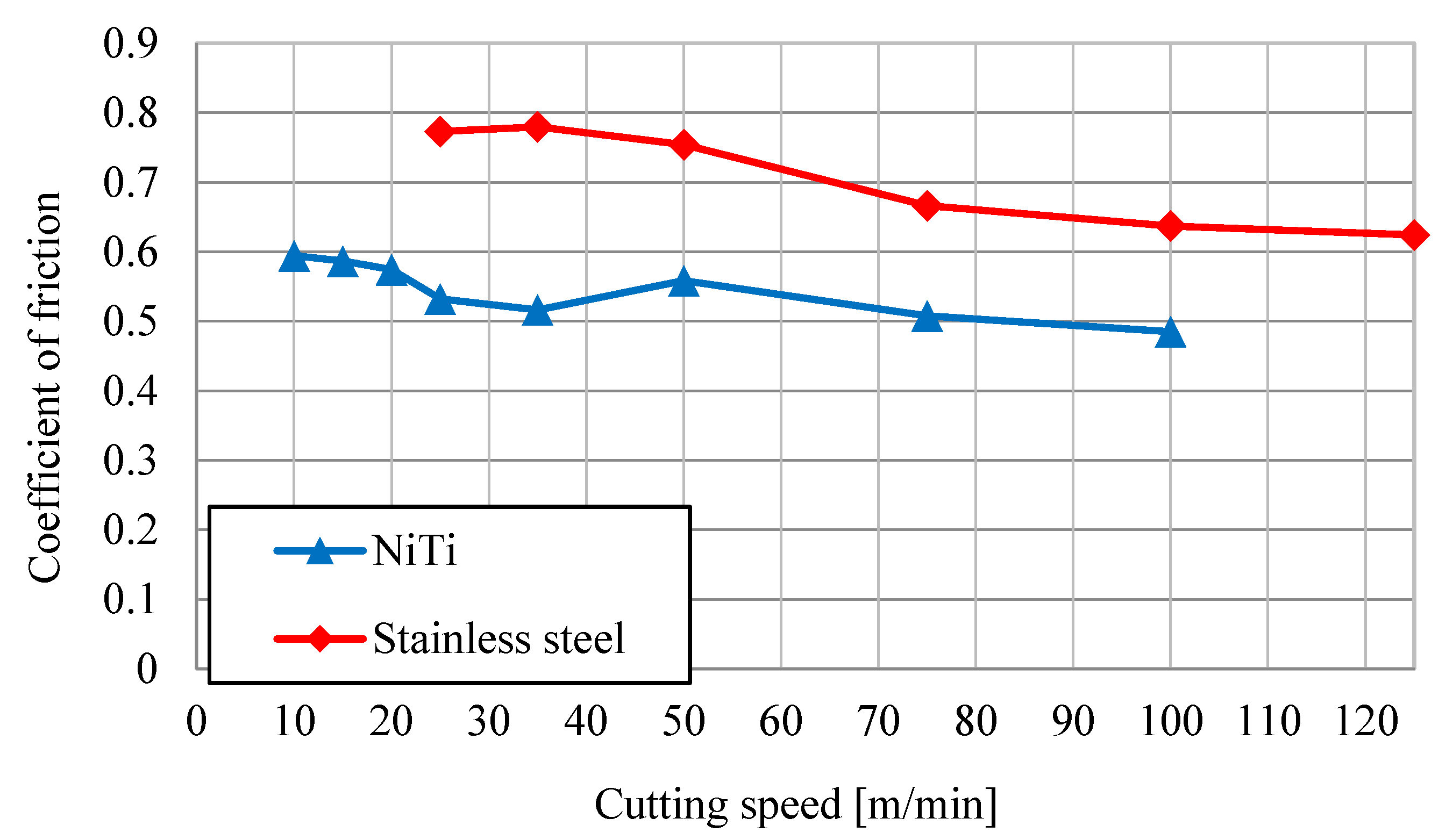
3.2. Examination of the Cause for Cutting Difficulty by Orthogonal Cutting

In three-dimensional cutting such as peripheral turning, there are many factors to consider, such as the tool nose radius and the tool geometry, which makes the phenomenon more complex. Thus, the cause for cutting properties identified (in turning) during the orthogonal cutting experiment needs further examination.
From Figure 3, the cutting temperature of NiTi alloy was higher than that of Ti-6Al-4V. It is considered that the thermal properties or mechanical properties of the material have an influence on the cause of the high cutting temperature of this alloy. Thus, in this experiment, to examine the influence of thermal properties on cutting temperature, stainless steel with similar thermal conductivity and specific heat to those of NiTi was used for comparison. Figure 7 shows the result of the cutting temperature measurement performed with the same tool–work thermocouple method as discussed in the previous section. Although the thermal conductivity of NiTi alloy (10–20 W/mK) is much lower than that of other metals (80 W/mK for iron, 44 W/mK for carbon steel), its cutting temperature is still much higher than that for stainless steel, which has similar thermal conductivity (16 W/mK) as NiTi. Therefore, the reason for the high cutting temperature is not the thermal properties of the material but the mechanical properties.
Because it was indicated that the high cutting temperature is caused by the mechanical properties of the material rather than its thermal properties, an analysis based on orthogonal cutting and the shear surface theory was performed to examine the cause of cutting difficulty for NiTi alloy. Figure 8 shows an example of the measurement of the cutting forces in orthogonal cutting. Cutting forces gradually increased in the beginning and then stabilized. However, after stopping the feed movement, cutting forces did not decrease rapidly to zero, but decreased gradually to a relatively stable value for a long duration, although there was no movement of the cutting tool in the feed direction at this moment. Regarding this unique phenomenon observed in orthogonal cutting, Kuppuswamy et al. [25] reported a phenomenon in which NiTi alloy underwent recoverable elastic deformation when the tool withdrew from the work material in micromilling of NiTi alloy. Although the usual recoverable strain of typical metallic materials is approximately 0.1–0.2%, Elahinia et al. [26] reported that NiTi alloy has a maximum recoverable strain of 8–10% due to its super elasticity. In addition, Chen et al. [27] investigated the dynamic compressive stress–strain behaviour of NiTi alloy and found that the complete recovery of residual deformation took a few seconds to several hours, which suggests that there is a relationship between the recovery behaviour of NiTi alloy and time. Terui et al. [28] investigated the stress relaxation properties of NiTi alloy and reported that NiTi alloy shows viscoelastic behaviour. These results suggest that in the cutting process of NiTi alloy, super elasticity might cause recoverable deformation of work materials, thus, cutting forces were measured after the stopping of the feed movement, and the long duration can be explained by the viscoelastic behaviour of NiTi alloy. Because work materials display elastic recovery in the radial direction during cutting, the flank face of tools and work materials is constantly in contact. From this, the effect of elastic recovery of NiTi alloy on the contact state between the tool and the work material was investigated by changing the relief angle of the tool. Figure 9 shows that changing the relief angle by 4 degrees (10° to 6°) caused the cutting and thrust forces to increase by 166 N and 170 N, respectively, indicating that there is a notable impact by elastic recovery of the work material. Therefore, the reason for the severe flank wear caused by cutting NiTi alloy (Figure 5 and Figure 6) is concluded to be the elastic deformation of the work material due to its super elasticity and associated high abrasiveness.
The calculated result for the cutting ratio based on the shear surface theory is shown in Figure 10. The chips of NiTi alloy are thicker than those of stainless steel, and the cutting ratio for NiTi alloy is high. The calculated shear angle (Figure 11) shows that the shear angle is high for NiTi alloy. These theoretical results indicate that the amount of shear deformation in NiTi alloy is small in the chip formation process. The result of shear and normal stresses in Figure 12 shows that both stresses are large for NiTi alloy. Shear stress is particularly large: it is 800–1000 MPa higher than that of stainless steel. It has been reported that NiTi alloy has very high deformation resistance [29]. This indicates that it is difficult to subject the workpiece to shear deformation during the cutting process, and the cutting force and stress increase in the cutting of NiTi alloy due to this characteristic. It has also been clarified that NiTi alloy has high deformation resistance and high internal friction [30]. Therefore, high internal friction and deformation resistance are the causes of the high temperature during NiTi alloy cutting. From the discussions above, it is concluded that these mechanical properties are major causes of the cutting difficulties of NiTi alloy.
Regarding the rake face, the calculation of the friction coefficient for the rake face (Figure 13) showed that the coefficient for NiTi alloy was lower than that for stainless steel. In cutting NiTi alloy, the adhesion of the alloy to the tool was not observed; thus, friction and adhesion at the rake face are not the causes of the difficulty in machining NiTi alloy.

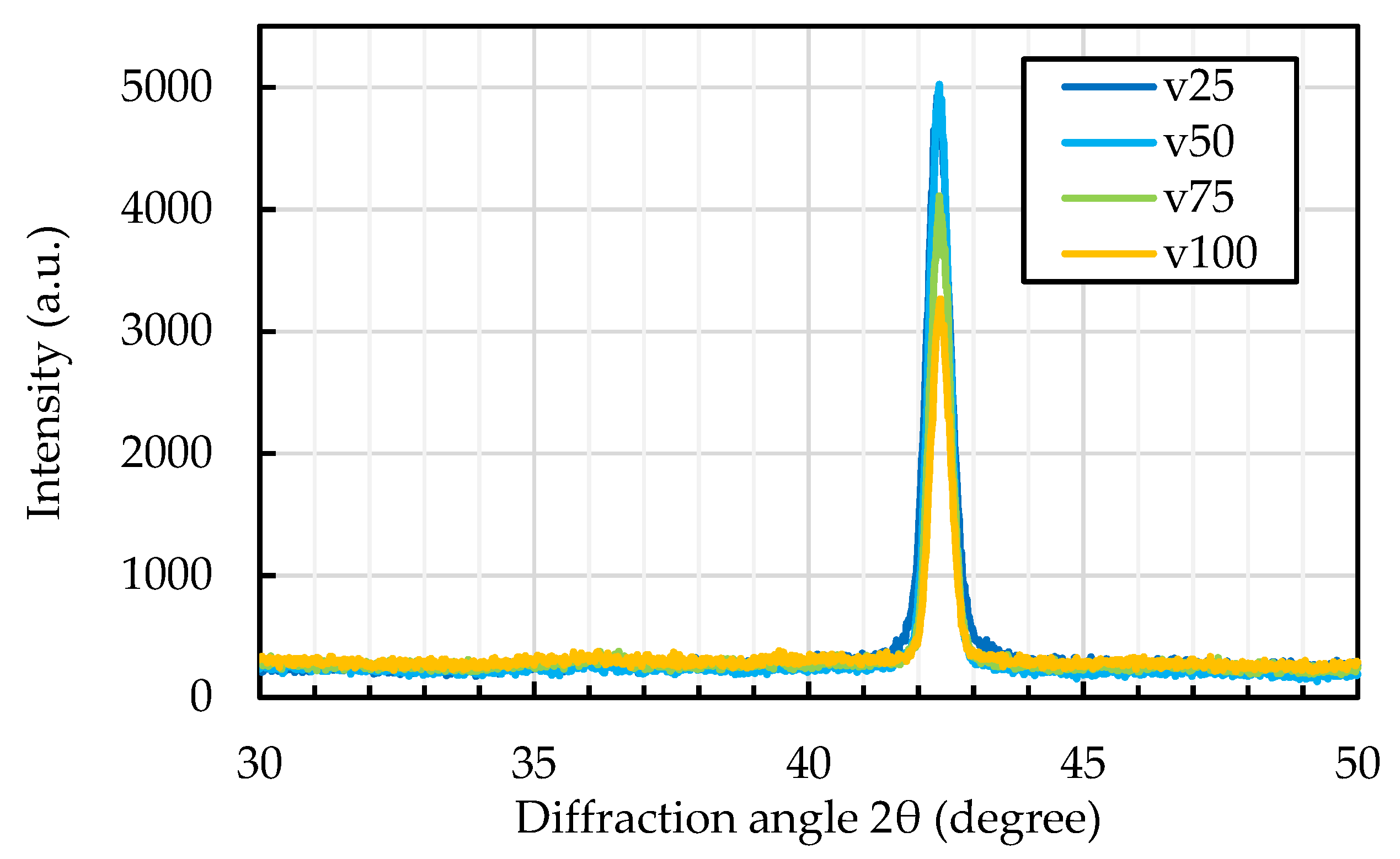
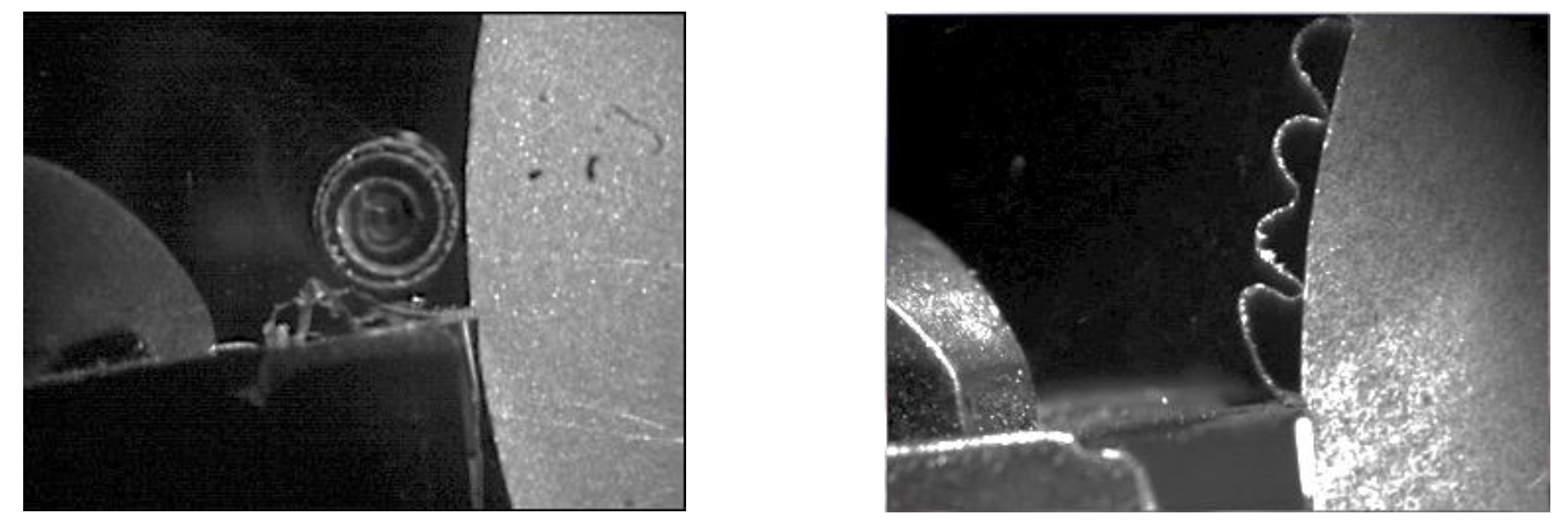
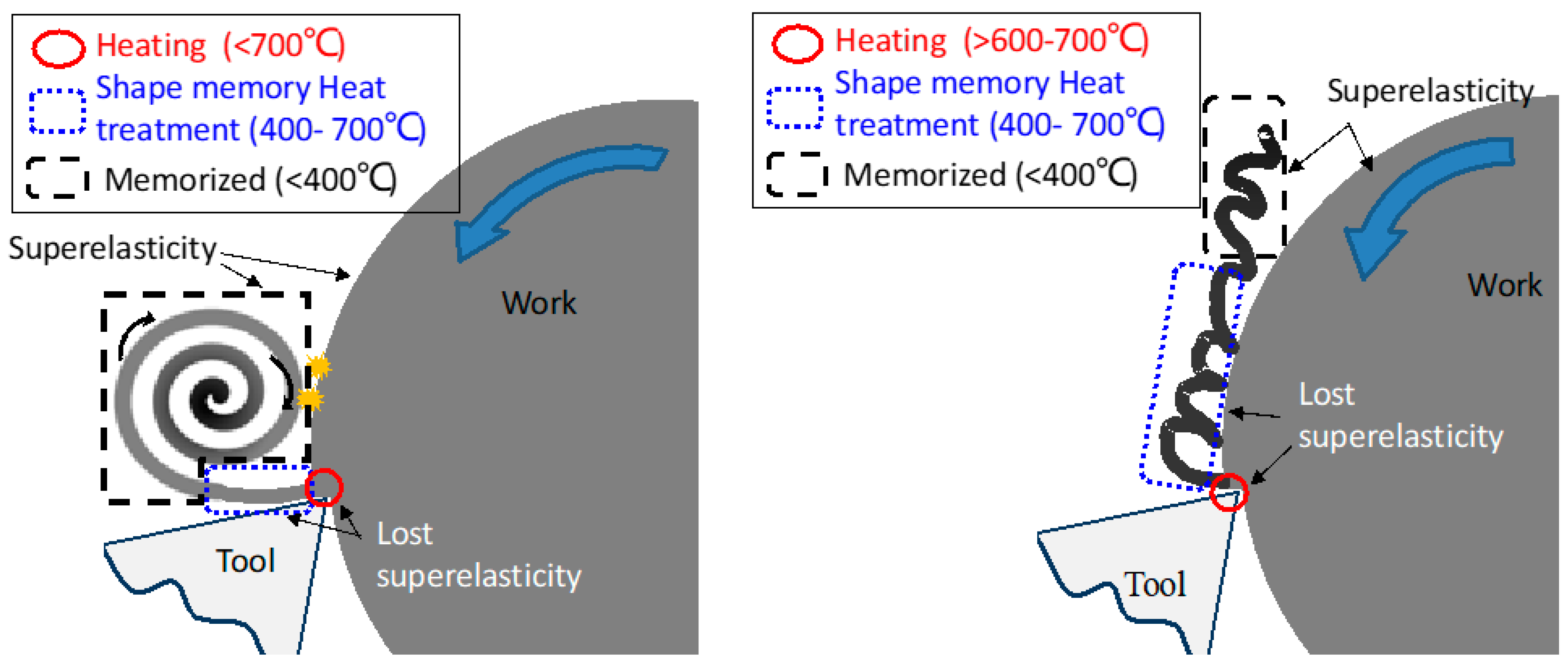
3.3. The Cause of the Very Low Chip Discharging Property in Cutting of NiTi Alloy

One of the difficult-to-cut properties of NiTi alloy is the deterioration of productivity due to its low chip controllability, as shown in Figure 14. Thus, the reason why chips are easily entangled in a cutting tool and a jaw chuck during cutting of NiTi alloy was investigated. NiTi alloy can undergo the shape memory process by maintaining the material at 400–500 °C for 30–40 min [31,32]. The temperature of the cutting point was above the shape memory process temperature, even at the ultra-low cutting speed of 10 m/min, as shown in Figure 3. This implies that the chip may have memorized its shape. To examine this hypothesis, experiments were performed to evaluate the shape memory effect. An example is shown in Figure 15. The chip used for this experiment was obtained in a cutting experiment at a low cutting speed. As shown in the figure, the chip was not easy to break when it was stretched at the normal temperature, and it returned to its original shape without permanent deformation, just like a spring when the load is removed (Figure 15A,B). Figure 16 shows the results of the X-ray photoelectron spectroscopy (XPS) analysis of the chip. All chips are in the austenitic phase (parent phase), as indicated by the observed peak around 42 degrees [33]. This observation implies that the chip exhibits super elasticity in the state of the host phase (austenitic phase). Then, the chip was cooled on dry ice at −78 °C to lower the materials’ temperature below the martensite transformation temperature (Mf: −42.2 °C) (Figure 15C); the real temperature of the chip was measured by touching the chip with a thermocouple. When tensile load was applied after the temperature of the chip reached or was below the martensite transformation temperature, the chip was easily deformed, and the permanent, plastic deformation remained, which can be seen in Figure 15D. When this chip was dipped in water (room temperature: 19 °C), as shown in Figure 15C, the chip then recovered its original curled form, as shown in Figure 15E. This experiment makes it clear that the chip of NiTi alloy undergoes the shape memory process immediately after it is formed under all cutting conditions in this study, even though the aging time at high temperature in the cutting process is extremely short. Furthermore, it was also found that because chips have super elasticity, they are not easily broken, rather they lengthen, and are easily entangled with a tool and a jaw chuck.
Figure 17 shows chips observed in orthogonal cutting. It can be seen in the figure that the shape of the chip was a spiral at the cutting speed of 30 m/min or less (ultra-low speed) and wavy at the cutting speed of approximately 30 m/min or more (hereinafter low speed), similar to the turning experiment described in the previous section. An example of the high-speed camera observation of the chip ejection in ultra-low- and low-speed cutting conditions is presented in Figure 18. It can be seen that the chip was ejected along the direction of the rake face of the tool in the ultra-low-speed condition, whereas the direction of the chip ejection was changed to the work material side in the low-speed condition.
Based on these results, a presumed formation mechanism of the NiTi alloy chip at ultra-low speed is presented in Figure 19. NiTi alloy used for the experiment exhibits super elasticity at room temperature, however, the vicinity of the cutting point is generally under high pressure and high temperature during the cutting process. It is known that the phase transformation temperature range of NiTi alloy ends at a temperature which is called the martensite desist (Md) temperature and, thus, NiTi alloy does not exhibit super elasticity above this Md temperature. Adharapurapu et al. [34] reported that the Md temperature of a 55.6Ni-44.4Ti (wt%) alloy with the Af tempearature 2 °C was 150 °C, which is about 150 °C higher than the Af temperature. Benafan et al. [35] also reported that the Md temperature of a 49.9Ni-50.1Ti (at%) alloy with the Af tempearature 105 °C was 310 °C, which was about 200 °C higher than the Af temperature. Therefore, it could be considered that the chip lost its super elasticity at the cutting point because the temperature at the cutting point exceeded the Md temperature, which could be determined as approximately 150–200 °C.
The chip heated at the cutting point (solid red circle) is quickly cooled in the process as it is discharged. However, because the temperature is above the shape memory treatment temperature inside the blue frame (dotted blue line) in the figure, the chip undergoes the shape memory process at this point. It is thought that the chip, having undergone the shape memory process and cooled (in the dot-dash black line), is then ejected in a spiral shape.

4. Conclusions

The present study closely examined the cutting properties of NiTi alloy via turning and orthogonal cutting experiments. This study examined the effect of super elasticity and the shape memory effect, which are unique properties of NiTi alloy, on the difficulty of cutting the material. The results showed that super elasticity caused notable elastic recovery of the workpiece during cutting, which causes flank wear. The cutting temperature of NiTi alloy was extremely high due to notable elastic recovery and high internal friction. This was true even at an ultra-low cutting speeds, which caused the plastic deformation and severe face wear of cutting tools. In the cutting of NiTi alloy, compared with other metals, the required cutting force was much larger. Because the shear angle of NiTi alloy is small, in contrast to the shear stress, which was extremely large in the orthogonal cutting experiment, the reason for the high cutting force required is the extremely large deformation resistance of the material. During the formation of chips, the temperature around the cutting point exceeded the shape memory process temperature, and the generated chips were shape memory processed. Furthermore, because the chips are super elastic, they are not easily broken and they are lengthened, and they are easily entangled with the cutting tool and the jaw chuck. The findings in this study that super elasticity and shape memory properties affect the difficult machinability of NiTi alloy are thought to contribute to understanding the cutting mechanism of this alloy and improve its productivity.

Author Contributions

Conceptualization, H.S. and K.S. (Katsuhiko Sakai); methodology, H.S. and K.S. (Katsuhiko Sakai) and T.N.; validation, H.S. and K.S. (Katsuhiko Sakai); formal analysis, H.S. and K.S. (Katsuhiko Sakai); investigation, H.S. and K.S. (Katsuhiko Sakai) and K.S. (Kazuki Sonoda) and H.Y. and T.N.; resources, H.S.; data curation, H.S. and K.S. (Kazuki Sonoda) and H.Y. and Y.K.; writing—original draft preparation, H.S.; writing—review and editing, H.S.; visualization, H.S.; supervision, H.S. and K.S. (Katsuhiko Sakai) and K.H.; project administration, H.S.; funding acquisition, H.S. All authors have read and agreed to the published version of the manuscript.

Funding

This research was partially funded by JSPS KAKENHI Grant Numbers 18K03871 and 16K17997 and O.S.G fund Grant Numbers 22-2(2020).

Conflicts of Interest

The authors declare no conflict of interest.

References

  1. Fadlallah, A.S.; El-Bagoury, N.; Gad, E.-R.M.S.; Ahmed, A.R.; El-Ousamii, G. An Overview of NiTi Shape Memory Alloy: Corrosion Resistance and Antibacterial Inhibition for Dental Application. J. Alloys Compd. 2014, 583, 455–464. [Google Scholar]
  2. Shabalovskaya, A.S. On the Nature of the Biocompatibility and on Medical Applications of NiTi Shape Memory and Superelastic Alloys. Biomed. Mater. Eng. 1996, 6, 267–289. [Google Scholar]
  3. Mishra, C.S. Applications of Shape Memory Alloys: A Review. J. Thin Films Coat. Sci. Technol. Appl. 2015, 2, 1–7. [Google Scholar]
  4. Maffiodo, D.; Raparelli, T. Three-Fingered Gripperwith Flexure Hinges Actuated by Shape Memory AlloyWires. Int. J. Autom. Technol. 2017, 11, 355–360. [Google Scholar]
  5. Morgan, B.N. Medical shape memory alloy applications—The market and its products. Mater. Sci. Eng. A 2004, 378, 16–23. [Google Scholar]
  6. Miyazaki, S.; Otsuka, K. Development of Shape Memory Alloys. ISIJ Int. 1989, 29, 253–377. [Google Scholar] [CrossRef]
  7. Mori, Y.; Ishida, S.; Satow, T.; Konnno, T.; Ohkawa, A.; Honma, T. Mechanical Working of a TiNi Shape Memory Alloy and It’s Application; Departmental Bulletin Paper of Tohoku University: Tohoku, Honshu, Japan, 1987; Volume 43, pp. 171–178. (In Japanese) [Google Scholar]
  8. Wu, K.S.; Lin, C.H.; Chen, C.C. A study on the machinability of a Ti49.6 Ni50.4 shape memory alloy. Mater. Lett. 1999, 40, 27–32. [Google Scholar] [CrossRef]
  9. Kaynak, Y.; Karaca, E.H.; Noebe, D.R.; Jawahir, S.I. Tool-wear analysis in cryogenic machining of NiTi shape memory alloys, A comparison of tool-wear performance with dry and MQL machining. Wear 2013, 306, 51–63. [Google Scholar] [CrossRef]
  10. Kaya, E.; Kaya, İ. Tool wear progression of PCD and PCBN cutting tools in high speed machining of NiTi shape memory alloy under various cutting speeds. Diam. Relat. Mater. 2020, 105, 1–10. [Google Scholar]
  11. Altas, E.; Gokkaya, H.; Ozkan, D. Investigation Of The Effects Of Machining Parameters On Tool Life And Surface Roughness During The Face Milling Of The NiTi Shape Memory Alloy With Uncoated Tools. Preprints 2020, 1, 2020080383. [Google Scholar]
  12. Weinert, K.; Petzoldt, V. Machining of NiTi based shape memory alloys. Mater. Sci. Eng. A 2004, 378, 180–184. [Google Scholar] [CrossRef]
  13. Weinert, K.; Petzoldt, V.; Kotter, D. Turning and Drilling of NiTi Shape Memory Alloys. CIRP Ann. 2004, 53, 65–68. [Google Scholar] [CrossRef]
  14. Weinert, K.; Petzoldt, V. Machining NiTi micro-parts by micro-milling. Mater. Sci. Eng. A 2008, 481, 672–675. [Google Scholar] [CrossRef]
  15. Kaynak, Y.; Karaca, E.H.; Noebe, D.R.; Jawahir, S.I. The Effect of Active Phase of the Work Material on Machining Performance of a NiTi Shape Memory Alloy. Metall. Mater. Trans. A 2015, 46, 2625–2636. [Google Scholar] [CrossRef]
  16. Kaynak, Y.; Robertson, W.S.; Karaca, E.H.; Jawahir, S.I. Progressive tool-wear in machining of room-temperature austenitic NiTi alloys, the influence of cooling/lubricating, melting, and heat treatment conditions. J. Mater. Process. Technol. 2015, 215, 95–104. [Google Scholar] [CrossRef]
  17. Kaynak, Y.; Karaca, E.H.; Jawahir, S.I. Cutting Speed Dependent Microstructure and Transformation Behavior of NiTi Alloy in Dry and Cryogenic Machining. J. Mater. Eng. Perform. 2015, 24, 452–460. [Google Scholar] [CrossRef]
  18. Kaynak, Y. Machining and Phase Transformation Response of Room-Temperature Austenitic NiTi Shape Memory Alloy. J. Mater. Eng. Perform. 2014, 23, 3354–3360. [Google Scholar] [CrossRef]
  19. Kaynak, Y.; Karaca, E.H.; Noebe, D.R.; Jawahir, S.I. Analysis of Tool-wear and Cutting Force Components in Dry, Preheated, and Cryogenic Machining of NiTi Shape Memory Alloys. Procedia CIRP 2013, 8, 498–503. [Google Scholar] [CrossRef] [Green Version]
  20. Kaynak, Y.; Karaca, E.H.; Jawahir, S.I. Cryogenic Machining of NiTi Shape Memory Alloys. In Proceedings of the 6th International Conference and Exhibition on Design and Production of Machines and Dies/Molds, Ankara, Turkey, 23–26 June 2011. [Google Scholar]
  21. Kaynak, Y.; Huang, B.; Karaca, E.H.; Jawahir, S.I. Surface Characteristics of Machined NiTi Shape Memory Alloy, The Effects of Cryogenic Cooling and Preheating Conditions. J. Mater. Eng. Perform. 2017, 26, 3597–3606. [Google Scholar] [CrossRef]
  22. Shaw, C.M. Metal Cutting Principles; Oxford University Press: Oxford, UK, 2012; ISBN 0198086113. [Google Scholar]
  23. Sekiya, K.; Yamane, Y.; Narutaki, N. Tool Wear under High Speed End Milling of Nickel-Base Superalloy Inconel 718. J. Jpn. Soc. Precis. Eng. 2004, 70, 1086–1090. [Google Scholar] [CrossRef] [Green Version]
  24. Itakura, K.; Kuroda, M.; Omokawa, H.; Itani, H.; Yamamoto, K.; Ariura, Y. Wear Mechanism of Coated Cemented Carbide Tool in Cutting of Super Heat Resisting Alloy Inconel 718. J. Jpn. Soc. Precis. Eng. 1999, 65, 976–981. [Google Scholar] [CrossRef]
  25. Kuppuswamy, R.; Yui, A. High-speed Micromachining Characteristics for the NiTi Shape Memory Alloys. Int. J. Adv. Manuf. Technol. 2017, 93, 11–21. [Google Scholar] [CrossRef]
  26. Elahinia, M.; Moghaddam, S.N.; Andani, T.M.; Amerinatanzi, A.; Bimber, A.B.; Hamilton, F.R. Fabrication of NiTi through Additive Manufacturing: A Review. Prog. Mater. Sci. 2016, 83, 630–663. [Google Scholar] [CrossRef] [Green Version]
  27. Chen, W.; Wu, Q.; Kang, H.J.; Winfree, A.N. Compressive superelastic behavior of a NiTi shape memory alloy at strain rates of 0.001–750 s−1. Int. J. Solids Struct. 2001, 38, 8989–8998. [Google Scholar] [CrossRef]
  28. Terui, A.; Tateishi, T.; Miyamoto, H.; Suki, Y. Study of Stress Relaxation Properties of NiTi Shape Memory Alloy. Trans. Jpn. Soc. Mech. Eng. C 1985, 51, 288–292. [Google Scholar]
  29. Müller, K. Extrusion of nickel–titanium alloys Nitinol to hollow shapes. J. Mater. Process. Technol. 2001, 111, 122–126. [Google Scholar] [CrossRef]
  30. Mazzolai, M.F.; Biscarini, A.; Coluzzi, B.; Mazzolai, G.; Villa, E.; Tuissi, A. Low-frequency internal friction of hydrogen-free and hydrogen-doped NiTi alloys. Acta Mater. 2007, 55, 4243–4252. [Google Scholar] [CrossRef]
  31. Motohashi, Y.; Ohsawa, K.; Hoshiya, T.; Okamoto, Y.; Ohmori, M. Grain Refinement of a Ti-Ni Shape Memory Alloy and Its Influence on Phase Transformation Characteristics. J. Jpn. Inst. Met. Mater. 1991, 52, 132–140. [Google Scholar] [CrossRef]
  32. Zeng, Y.C.; Cao, S.; Li, Y.Y.; Zhao, X.Z.; Zhu, W.Z.; Wang, X.D.; Ma, X.; Zhang, P.X. Two-step constrained aging treatment enabled superior two-way shape memory effect and elevated R-phase transformation temperatures in a rapidly solidified Ni51Ti49 alloy. J. Alloys Compd. 2019, 785, 1180–1188. [Google Scholar] [CrossRef]
  33. Lopes, N.; Silva, L.; Santos, L.; Buono, V. Surface Characterization of NiTi Superelastic and Shape Memory Alloys after Electrolytic Polishing. Mater. Res. 2017, 20, 1–8. [Google Scholar] [CrossRef] [Green Version]
  34. Adharapurapu, R.; Jiang, F.; Vecchio, S.K.; Gray, T.G. Response of NiTi shape memory alloy at high strain rate: A systematic investigation of temperature effects in tension-compression asymmetry. Acta Mater. 2006, 54, 4609–4620. [Google Scholar] [CrossRef]
  35. Benafan, O.; Noebe, D.R.; Padula, A.S.; Garg, A.; Clausen, B.; Vogel, S.; Vaidyanathan, R. Temperature dependent deformation of the B2 austenite phase of a NiTi shape memory alloy. Int. J. Plast. 2013, 51, 103–121. [Google Scholar] [CrossRef]
Figure 1. Schematic of an orthogonal cutting.
Jmmp 04 00124 g001
Figure 2. Schematic of an orthogonal cutting.
Jmmp 04 00124 g002
Figure 3. Cutting temperature at different cutting speeds for various materials.
Jmmp 04 00124 g003
Figure 4. Relationship between the cutting speed and force.
Jmmp 04 00124 g004
Figure 5. Pictures of tool wear at different cutting speeds and for cutting NiTi and Ti-6Al-4Vs. (a) Top view, (b) side view, (c) tip nose.
Jmmp 04 00124 g005
Figure 6. Relationship between the cutting speed and flank wear.
Jmmp 04 00124 g006
Figure 7. Measured cutting temperature in orthogonal cutting.
Jmmp 04 00124 g007
Figure 8. Waveforms of cutting forces measured in the orthogonal cutting of NiTi alloy (v = 20 m/min, f = 0.05 mm/rev, t = 2 mm).
Jmmp 04 00124 g008
Figure 9. Cutting force with relief angle change in orthogonal cutting (v = 20 m/min, f = 0.05 mm/rev, t = 2 mm).
Jmmp 04 00124 g009
Figure 10. Cutting ratio calculated from the shear surface theory.
Jmmp 04 00124 g010
Figure 11. Shear angle calculated from the shear surface theory.
Jmmp 04 00124 g011
Figure 12. Shear stress and normal stress calculated from the shear surface theory.
Jmmp 04 00124 g012
Figure 13. Coefficient of friction calculated from the shear surface theory.
Jmmp 04 00124 g013
Figure 14. Tangling of chips with the jaw chuck and the cutting tool (v = 50 m/min, f = 0.1 mm/rev, t = 1.0 mm).
Jmmp 04 00124 g014
Figure 15. Experiment to evaluate the shape memory effect of the chip. (A) original chip shape or unloading the thensile load (B) applying the tensile load at room temperature (C) cooling the chip on dry ice (D) applying the tensile load after cooling the chip (E) dipping the chip of D in water.
Jmmp 04 00124 g015
Figure 16. Results of XPS analysis of the chips.
Jmmp 04 00124 g016
Figure 17. Change in chip shape at different cutting speeds.
Jmmp 04 00124 g017
Figure 18. High-speed camera observation of the chip discharge state (left: v 25 m/min, right: v 100 m/min).
Jmmp 04 00124 g018
Figure 19. Shape memory mechanism of chip (left: v 25 m/min, right: v 100 m/min).
Jmmp 04 00124 g019
Table 1. Cutting conditions (turning experiment).
TurningOrthogonal Cutting
Cutting speed (m/min)25, 50, 75, 10010–130
Feed (mm/rev)0.10.1
Depth of cut (mm)12
AtmosphereDry
ToolCarbide (non-coated, K10)
Publisher’s Note: MDPI stays neutral with regard to jurisdictional claims in published maps and institutional affiliations.

