The Capabilities of Spark-Assisted Chemical Engraving: A Review


1
Department of Mechanical and Mechatronics Engineering, Rafik Hariri University, Mechref, Damour 10, Lebanon
2
Department of Mechanical and Manufacturing Engineering, Ontario Tech University, Oshawa, ON L1G 0C5, Canada
*
Author to whom correspondence should be addressed.
J. Manuf. Mater. Process. 2020, 4(4), 99; https://0-doi-org.brum.beds.ac.uk/10.3390/jmmp4040099
Submission received: 1 September 2020
/
Revised: 5 October 2020
/
Accepted: 10 October 2020
/
Published: 23 October 2020
Abstract
:Brittle non-conductive materials, like glass and ceramics, are becoming ever more significant with the rising demand for fabricating micro-devices with special micro-features. Spark-Assisted Chemical Engraving (SACE), a novel micromachining technology, has offered good machining capabilities for glass and ceramic materials in basic machining operations like drilling, milling, cutting, die sinking, and others. This paper presents a review about SACE technology. It highlights the process fundamentals of operation and the key machining parameters that control it which are mainly related to the electrolyte, tool-electrode, and machining voltage. It provides information about the gas film that forms around the tool during the process and the parameters that enhance its stability, which play a key role in enhancing the machining outcome. This work also presents the capabilities and limitations of SACE through comparing it with other existing micro-drilling and micromachining technologies. Information was collected regarding micro-channel machining capabilities for SACE and other techniques that fall under four major glass micromachining categories—mainly thermal, chemical, mechanical, and hybrid. Based on this, a figure that presents the capabilities of such technologies from the perspective of the machining speed (lateral) and resulting micro-channel geometry (aspect ratio) was plotted. For both drilling and micro-channel machining, SACE showed to be a promising technique compared to others as it requires relatively cheap set-up, results in high aspect ratio structures (above 10), and takes a relatively short machining time. This technique shows its suitability for rapid prototyping of glass micro-parts and devices. The paper also addresses the topic of surface functionalization, specifically the surface texturing done during SACE and other glass micromachining technologies. Through tuning machining parameters, like the electrolyte viscosity, tool–substrate gap, tool travel speed, and machining voltage, SACE shows a promising and unique potential in controlling the surface properties and surface texture while machining.
1. Introduction
The evolution of micro-technology has vastly extended the frontiers of micromachining and its capabilities. This has ultimately increased the significance of materials that can withstand complex machining conditions and possess unique properties. Among these are non-conductive materials—like glass and ceramics, which have fortunately paved the way for solving new challenges in a myriad of applications in biomedical, biotechnological, and optoelectronic fields [1,2].
Regarding ceramics, a range of unique properties like resistance to corrosion and endurance of high temperatures make them compatible materials for micromachining [3]. Similarly, glass has proved to be very efficient in micro-applications considering its transparency and other significant material properties such as chemical resistance and thermal conductivity [4,5]. Consequently, this has established ceramics and glass as substantial materials utilized in the fabrication of micro-devices and micro-features. In fact, the micromachining of these materials was further advanced with the growth of the microelectromechanical system (MEMS) field. Optical sensors, microfluidic devices, micro-pumps, and micro-reactors, to name a few, are MEMS devices that depend on the micromachining technology of several non-conductive materials like glass, ceramics, and composites [6]. However, conventional methods like mechanical, laser, and chemical machining can either result in deteriorated surface quality or would require complex and expensive systems when applied on non-conductive materials [6]. One emerging method for micromachining non-conductive materials is electrochemical discharge machining which is a hybrid method. It relies on thermally accelerated etching to remove materials from the surface [7]. This novel hybrid method is referred to in literature under diverse names like “Electrochemical Discharge Machining”, “Discharge Machining of Nonconductors” [8], “Electrochemical Arc Machining” [9], “Electrochemical Spark Machining” [10], and “Spark-Assisted Chemical Engraving” [11].
Spark-Assisted Chemical engraving, or SACE for short, is a hybrid technology that integrates chemical and thermal processes in the machining of several non-conductive materials. The technology is based on electrochemical discharge phenomena. Machining occurs due to thermally accelerated etching and machining zone temperature reaches levels up to 600 °C [12,13]. Despite the existence of other machining technologies including mechanical, chemical, and thermal, SACE has advantages over other processes used for micromachining non-conductive materials. Mainly, SACE does not require expensive or complex setup and can establish a variety of features (1 D to 2.5 D) with aspect ratios (beyond 10) [5] and acceptable resolution (less than 0.5 microns surface roughness) at a relatively fast machining speed. This makes SACE a compatible technology for rapid prototyping of glass micro-parts and devices. Furthermore, SACE offers the possibility of modifying the surface properties, like texture while machining [14], fabricating micro-features on nanofiber layers [15] and modifying the surface of micro-features [16]. The research done about SACE in the past years has shown a promise that this technique can be further developed to establish micro-features with higher surface quality and at higher speed. Moreover, this technique has the potential to control the surface composition and structure while machining in a single step, contrary to the majority of other micromachining methods. Furthermore, it was demonstrated that SACE, in comparison to other manufacturing techniques like chemical, mechanical, and thermal, can eliminate intermediate steps in the process of manufacturing microfluidic and other lab-on-a-chip devices [17]. In rapid prototyping, sealing the machined devices through bonding them to glass is a critical step that might cause failure in the device manufacturing if not done properly [18,19,20]. Postprocessing steps, like polishing or particle removal, are needed to compensate for any formation of bulges and bonding defects caused while machining by thermal [21,22,23] and mechanical [24,25] processes, respectively. Recently, a glass device that was machined using SACE was successfully fusion bonded at high annealing temperature [26], and its performance was evaluated qualitatively and quantitatively [17]. Investigations revealed good bonding and no leakage.
SACE process can be summarized as follows. The sample to be machined is dipped in an electrolytic solution in a position just below a machining tool, referred to as the tool-electrode. This machining tool is a metallic electrode, usually a cathode, connected through a Direct Current (DC) voltage to another metallic counterelectrode (anode), as shown in Figure 1.
Both electrodes are also dipped in the solution, with the cathode having a smaller surface area than that of the anode. When the applied voltage reaches a critical value of around 30 V, the previously formed bubbles coalesce into a gas film, causing emissions of light and generations of high energy electrical discharges [6,7]. These conditions contribute to the machining of the workpiece. This novel technology can be used on non-conductive materials like glass and ceramics to perform several machining operations like drilling holes, milling micro-channels and micro-grooves, die-sinking, cutting micro-slits, turning, and grinding as shown in Figure 2.
This paper presents a literature review of the research findings of the past 15 years on the novel Spark-Assisted Chemical Engraving (SACE) technology. Although other review papers exist on the topic [27,28], this paper is a detailed review identifying the advantages as well as limitations of SACE compared to other micromachining techniques in terms of drilling and machining. This revealed insights on the position of SACE from a comparative perspective with other micromachining technologies. A figure that presents the capabilities of SACE and other micro-channel machining methods from the perspective of the machining speed and resulting feature geometry was created. The review helps researchers identify the gaps that need to be filled out in terms of SACE process development and enhancing its capabilities especially from the resulting machining quality and process speed perspectives, therefore extending its applications. SACE process is currently being used to micro-machine parts on the industrial level where Posalux SA released the first SACE machine on the market few years back [29].
The remainder of the paper is organized in six major sections. Section 2 describes the basic setup of SACE technology and explains the different machining modes used in literature. Section 3 presents the gas film, a substantial element in SACE machining. Section 4 summarizes the effects of the three most influencing process parameters in SACE machining: electrolyte, tool-electrode, and machining voltage. Section 5 compares SACE against other micromachining technologies in terms of the machining speed, surface quality, and surface functionalization, mainly texturing. Last but not least, Section 6 wraps up our findings and presents concluding remarks and outlook
A detailed outline showing all sections and subsections is provided below.
2. SACE Setup and Machining Modes
A machining head and a processing cell, mounted on the XYZ of a Cartesian robot, compose the setup of a conventional SACE machine, as shown in Figure 3. The machining head embodies the following; the tool-electrode, a flexible structure that holds the tool and allows it to move freely with a displacement z along the Z-direction, a voice coil actuator that can control z, and an optical sensor to measure z. The processing cell can move in the XY directions and embodies the workpiece, counterelectrode, and electrolytic solution.
Regarding the machining modes, there are two main modes commonly used in literature. The first mode is the gravity feed. In this mode, the tool is pushed down by a constant force F—which is basically the weight of the structure holding the tool—to maintain contact between the tool (source of heat) and the workpiece. Until now, the gravity-feed is considered the simplest strategy as it has no complicated technical details. The tool–workpiece contact ensures similar temperatures between the tool and machining zone. The other common machining mode is the constant-velocity feed. This machining mode, in comparison to the first one, feeds the tool with a constant feed rate f. Contrary to gravity-feed machining where the tool is always in contact with the substrate, in constant-velocity feed the tool occasionally contacts the surface. Tool–substrate contact can be avoided especially for shallow machining depth (less than 200 µm usually) depending on the chosen tool feed rate. Recently, this strategy has been integrated with force-feedback algorithms to reduce the tool–substrate contact and hence tool bending even for high depths. Basically, the contact force between the tool and workpiece is monitored and minimized while machining. It is worth mentioning that the gap between the tool and workpiece is not constant and, until now, controlling it is not yet possible due to the fact that the tool is conductive while the substrate is non-conductive. This hinders an accurate control of the process and hence the machining integrity and surface quality as the two machining limiting factors, heating and flushing, differ depending on this gap. As mentioned earlier, this process is based on thermally accelerated etching, and therefore the presence of electrolyte in the machining zone through flushing it and the proximity of the tool, which is the heat source, to the substrate are crucial to the machining progress [7]. Figure 4 illustrates the major differences between the two main strategies.
The mentioned strategies can be used in drilling micro-holes as well as machining micro-channels, micro-grooves, and micro-structures. However, the gravity-feed strategy has been the most widely used in drilling applications. The advantages and limitations for these strategies are discussed in Section 2.1 and Section 2.2. Other machining modes exist which depend on feedback algorithms developed to enhance machining performance, such as current-feedback and force-feedback machining. Furthermore, counter-resistant feeding mechanism was recently proposed by Xu et al. [31] which offers some advantages over the conventional gravity-feed strategy. These machining modes will be presented in Section 2.3.
2.1. Gravity-Feed Machining
In this machining mode, the tool remains in contact with the surface of the workpiece, where the gravity effect allows it to keep pushing on the surface. Machining progress can be monitored without the use of any additional signal due to this continuous contact. In gravity-feed drilling, machining can be divided into two basic regimes: Discharge regime and hydrodynamic regime [32]. The first regime is in the case of low depths (typically less than 200 µm), and is controlled mainly by the amplitude of applied voltage where drilling speed can reach up to 100 µm/s for a certain applied voltage (33 V). In the latter regime, drilling depth is high (>200 µm), and the drilling speed reduces drastically as machining is hindered by insufficient flushing of electrolyte into the machining zone. Maillard et al. [33] identified four distinguished types of holes based on the applied voltage and drilling depth. Cylindrical holes having smooth surfaces were successfully machined at low depths (<100 µm) or a low voltage (28 V and depths up to 300 µm). Jagged holes appeared at higher depths (200–300 µm, 30 V), holes with some heat-affected zones (HAZ) were the results of higher voltages (>30 V), and holes with cracks appeared at 37 V. In general, it was found that as machining depth exceeds 200 µm, it becomes more challenging to limit HAZ and width overcut of holes. Several efforts have been made in the light of improving the machining performance. Wüthrich et al. [34] revealed that the addition of tool vibrations decreased the machining time to half its initial value where 300 µm deep micro-holes were drilled in about 10 s or less. A similar approach to enhance flow of electrolyte into deep holes was done by Han et al. [35] through applying pulsed voltage and ultrasonic vibrations to the electrolyte. The approach effectively increased the machining depth (as shown in Figure 5) but increased overcut and geometric inaccuracies.
This approach used a side-insulated tool of diameter 0.2 mm along with pulsed voltage and proved better in improving hole geometry (diameter was reduced from 0.426 mm to 0.328 mm) and depth increased to a value of 550 µm. Another combination of using a pulse voltage along with an unconventional tool geometry (having a front that is flat-sidewall-flat) was done by Zheng et al. [36] at a machining depth of 450 µm. Taper was significantly reduced where hole entrance decreased from 570 µm (for cylindrical tool) to 330 µm.
Furutani et al. [37] achieved a groove depth of around 600 µm at a rotation speed of 30 rotations per minute and 40 V applied voltage with smooth bottom surface and some micro-cracks. The groove’s depth, width, and surface roughness increased as the applied voltage increased. These values were achieved while rotating the workpiece to allow the flow of fresh electrolyte into the machining zone.
Another approach to facilitate the flow of electrolyte to the tool–workpiece gap was done by Mehrabi et al. [38] using pressurized injection systems at various pressure levels and using hollow tool-electrodes with several outer and inner diameters. One end of the tool was in contact with the workpiece while the other was connected through a tube to an injection system. The anode was made of steel and placed 10 cm away from the cathode. Under a machining voltage of 75 V, hole depth was improved by 70% using a 1.7 mm electrode diameter and 60% and 55% using an electrode diameter of 1.4 mm and 1 mm, respectively. These results showed an increase in materials removal rate (MRR). However, oversized hole diameter can result from high injection pressure.
Overall, this strategy clearly demonstrated successful results especially for hole depths below 300 µm. In the case of hole depth above 300 µm, this strategy suffers from the drawback of limited flushing and hole deformation due to the continuous tool–workpiece mechanical contact. Another drawback is the high possibility of tool bending in case of small tool sizes, which limits the minimum diameter of used tools to 200 µm.
2.2. Constant Velocity-Feed Machining
In this machining mode, the tool is fed with a constant feed rate f offering the potential of avoiding any contact between the tool and workpiece, which can solve the problem of tool bending. The tool here is moved towards the substrate at a constant feed rate where it proceeds vertically downward while machining. When the feed rate is lower than the MRR, a variable tool–workpiece gap is created. While this gap enhances the local flow of electrolyte at the machining zone, it causes the last to possess a lower temperature compared to that of the tool-electrode (the heat source). Moreover, and up to this date, the gap cannot be controlled which hinders online monitoring of the machining progress. Recent efforts have been made by Abou Ziki et al. [39] to measure the tool–substrate gap towards the end of machining. This was done for several machining conditions and a thermal model was constructed to explain the gap values measured. Temperature of machining zone and local flushing were identified to be the two factors that affect the value of the gap, which was found out to be around 10 µm or less in [39]. The model implies that the gap grows until the temperature of the surface reaches the melting temperature of the electrolyte salt. The gap does not grow further for lower temperature since the electrolyte solidifies and etching stops. Note that initially, at zero gap, the surface temperature is considered to be similar to the tool temperature. Other efforts to control and monitor the process are exerted through developing force feedback algorithms, which is discussed in depth in the following section.
Drilling Forces
A novel attempt by Abou Ziki et al. [30] paved the way in developing force feedback algorithms that are expected to improve the machining performance. During drilling, the tool moves vertically downwards at a specific feed rate while the machining head (that holds the tool) acts as a force sensor that measures the forces applied on the tool. In this study, a feedback signal based on the contact forces between the tool-electrode and the workpiece was proposed as a possible way to monitor the process. Three different force patterns were distinguished based on the hole depth (feed rate) and applied voltage. Electrolyte flushing and workpiece surface heating were identified as the limiting factors in cases of high depth and low depth respectively. It was found that the range of allowable tool feed rates increases (up to 70 µm/s) for smaller tool diameters (250 µm) and at a machining voltage of 33 V. The forces were also studied from the current signal point of view where a correlation was identified between applied forces and current shifts as shown in Figure 6.
A further investigation on the nature of the drilling forces occurring at the tool-substrate vicinity was done by Abou Ziki et al. [40] and revealed that a chemical bond can form between the tool and the glass surface even before any contact between them occurs. This bond was explained as the result of the formation of an adhesive glass melt (socium silicate) during the etching process. Basically, the contact forces that exist towards the end of machining, called Pressing Forces, start decaying after the applied voltage is switched off due to tool-retraction caused by a temperature drop in the machining zone. These decaying forces can either decay into a positive value or a negative value. In the case where pressing forces are low (<0.25 N), forces decay negatively indicating that the tool is being pulled downwards toward the workpiece then values go back to zero indicating that the tool–glass bond was broken. This phenomenon results in interrupted drilling and its causes vary depending on machining conditions and machined geometry. In case of deep holes and continuous tool–glass contact, machining temperature is similar to that of the tool, and machining is hindered by insufficient electrolyte flushing. In the case of low depth and shallow surfaces, machining temperature is equal to vaporization temperature of electrolyte, and machining is hindered because of insufficient heating of workpiece surface. This causes the formation of a glass melt in the tool vicinity that creates a tool-glass adhesive bond [41].
Another limitation of this strategy (other than the un-controlled gap) is the possible damage or breaking caused by high bending forces on the tool if feed rates weren’t properly selected. The effects of various parameters (electrolyte concentration, tool diameter, feed rate, and applying a magnetic field) on tool bending forces was investigated by Hajian et al. [42]. The optimum feed rates for each set of machining conditions were presented. It was found that as the applied voltage and electrolyte concentration increased, bending forces decreased. Another observation is that for lower electrolyte concentrations (typically 15 wt%), applying a magnetic field significantly reduces the bending forces. Didar et al. [43] revealed that the optimum values for machining a high quality micro-channel with a specific depth (50 to 300 µm) were to choose values less than 32 V, 30 µm/s, and 15 µm for applied voltage, tool velocity, and tool-surface distance, respectively. Singh et al. [44] achieved a 135 µm deep micro-channel using an optimum process parameters of 59 V, 3 ms on time and 3 ms off time, 12 mm/min feed rate, and 21 wt% NaOH concentration. More details on other capabilities of constant-velocity feed machining are presented in Section 4.
2.3. Other Machining Modes
Although gravity feed machining and constant-velocity feed machining are the commonly used methods in SACE, there are other techniques attempted to further control and enhance machining. Cao et al. [45] achieved an aspect ratio of 2 using a tool at 31 µm diameter. Using a mechanical-based contact detector, a closed loop feedback was developed through monitoring contact forces that are applied to the load cell. Although Wüthrich et al. [46] proposed using the force signal for feedback machining, the developed algorithm was still preliminary. Later, Abou Ziki [5] achieved holes with an aspect ratio of 9 drilled in 13 s through developing force-feedback algorithms that enhanced the drilling performance (decreased drilling time). Another type of feedback machining is using the current signal. Wüthrich et al. [47] studied the current signal as a possible way to enhance machining performance, but no significant outcome was produced. Morrison et al. [48] applied a proportional feedback controller to reduce variability (i.e., decrease the standard deviation) in SACE drilling. In this proposed method, the current depth is fed back to the voltage signal, thus forming a closed loop which improves the quality of drilled holes.
With gravity-feed machining, achieving repeatability is still an unsolved issue. Wüthrich and Hof [49] revealed that even when using identical machining parameters, the process is not yet repeatable. Xu et al. [31] plotted workpiece displacement as a function of time using the conventional gravity feeding strategy and concluded that the main causes for unrepeatable machining were tool deviation (resulting from elastic deformation of the chamber) and the uncontrolled damping and mechanical friction during feeding. In consequence, they proposed a new flexible fixture, where the force exerted on the tool is not constant but varies as a function of machining depth in a decreasing pattern (see Figure 7). Therefore as the machining proceeds (for higher depths), the force exerted on the tool is reduced.
This “symmetrical” set-up achieved 55% deeper holes compared to the conventional gravity feeding method and resulted in more consistent drillings as shown in Figure 8. The authors also observed that cracks and roundness error become negligible as voltage decreases confirming the idea that the decreasing pattern of contact forces will prevent bubble accumulation in the hydrodynamic regime.
This setup was further enhanced in [50] through applying a magnetic field in a 20 wt% NaOH electrolyte while using a 0.5 mm tungsten carbide tool-electrode. The gas film formation around the tool was recorded by a high-speed camera, and an ~9% reduction in thickness was observed with the magnetic field compared to the case without. Furthermore, at 40 V, machining time and radius of hole entrance were reduced by 68% and 18.5%, respectively.
3. The Gas Film
As mentioned earlier in the introduction, SACE process is based on electrochemical discharge phenomenon. The electrical discharges, generated from the tool tip during the process cause the local heating effect, making the tool the heat source. These discharges occur through the gas film that forms around the tool and isolates it from the surrounding electrolyte. The properties of this gas film affect the quality and repeatability of the process, making it a substantial element in SACE machining [7]. For example, the discharge activity is influenced by the shape of the gas film, thus the resulting overcut is affected. The gas film forms and breakdowns every few milliseconds and keeps on reforming continuously during the machining process. Therefore, it influences the local electrolyte flow dynamics in the tool vicinity which in turn has effects on the surface topography and quality. Consequently, it is fundamental to understand the factors and parameters that influence the gas film properties. The gas film formation cycle was divided into five regions in past literature [51,52,53,54] based on the mean I–U characteristics curve shown in Figure 9a. The five regions (Figure 9b) are summarized below.
- OA: Thermodynamic Region: The water’s decomposition potential is not yet reached and no electrolysis occurs.
- AB: Ohmic Region: Water electrolysis occurs.
- BC: Limiting-Current Region: Bubbles coalesce saturating the current.
- CD: Transition Region: A gas film starts forming around the tool covering its surface; machining becomes possible. A current density of around 1 is generally required for gas film formation.
- DE: Arc Region: Nucleation sites of actives bubbles are covered now with the gas film, and current is transported through microlevel arc discharges.
Basically, the qualities used to indicate the stability of the gas film are its shape, thickness, lifetime, and formation time, as well as the standard deviation of discharge current. Many factors (shown in Figure 10) influence these qualities, these mainly include the machining conditions (voltage, tool immersion depth and motion, electrolyte temperature and composition), the electrolyte properties (surface tension, viscosity, and resistivity), and tool-electrode properties (surface wettability, size, and geometry).
Therefore, it can be said that the main forces that affect the gas film stability are buoyant forces, surface tension and inertial forces. Stability is enhanced when the gas film is uniform, thinner and has a constant lifetime, and when there are low fluctuations in current signal indicated by the standard deviation of discharge current. This section presents a review on the recent literature done regarding this topic.
Investigations through current/voltage values obtained while machining on glass were done by Fascio et al. [53] to understand the nature of bubble formation in the tool vicinity. The machining domain of SACE was identified generally in the region where applied voltage exceeds 25 V. It was speculated that as voltage increases above this limit, temperature of the area surrounding the tool becomes equal to the electrolyte boiling temperature, thus creating vapor bubbles. As a result, the working surface area of the tool becomes covered with bubbles that coalesce into a gas film isolating it from the electrolyte. This film breaks and reforms in a continuous cycle every few milliseconds, leading to current fluctuations in this region. The average gas film formation time and lifetime differ based on the machining conditions [55].
Wüthrich et al. [56] experimentally measured the thickness of the gas film and derived a theoretical model for estimating its value. The average thickness of the gas film was linked to the average diameter of bubbles existing when the gas film starts forming. The diameter and shape of these bubbles are influenced by the wettability of the electrode on one hand, and the average distance between active-bubble nucleation sites on the other hand. Knowing that is the mean distance between the nucleation sites, the mean bubble height can be calculated through estimating the critical voltage using Equation (1):
where is the critical voltage, is the size of a bubble, is the number of bubbles/total number of nucleation sites, is the electrode surface, R is the inert electrode resistance of electrolyte, is the mean detachment frequency, α is the faradic gas-generation coefficient, and is the percolation threshold. Then, authors considered that tool radius is much greater than the gas film thickness , and estimated as shown in Equation (2):
Previous models linked the applied voltage with activation of nucleation sites [57,58,59] which indicates a correlation between gas film thickness and critical voltage. Authors investigated the addition of soap to reduce film thickness. Using a conical stainless-steel tool, the addition of liquid soap decreased variance error of hole diameter from 20 µm at 32 V applied voltage and 30 wt% NaOH electrolyte, to 5 µm at 20 V and same electrolyte concentration. Thus, authors concluded that decreasing the thickness of the gas film, which stabilizes it, will result in fewer fluctuations, therefore creating better repeatability. However, the drawback is the increase in machining time. In this experiment, gas film thickness was found out to be between 100 µm and 200 µm. Three strategies were identified to reduce gas film thickness: The first is the utilization of hydrodynamic fluxes, like rotating the tool or the electrolyte, or both. The second is altering the tool wettability (or the forces at the tool vicinity), which can be done through adding soap for example. The third is controlling density of bubble nucleation sites (i.e., controlling the distance between active bubble-nucleation sites). Han et al. [60] used a side-insulated tool-electrode as a possible method to improve the uniformity of spark energy generation. The side insulated tool localizes gas film formation within a specific area of the tool-electrode, preserving a consistent active tool region constantly in contact with electrolyte. However, effects of side-insulation become negligible if immersion depth increased beyond 3.2 mm for the given machining conditions. During a 10 ms machining time, an 82% decrease in the standard deviation of peak spark value (431 mA to 76 mA) was achieved using the side-insulated tool at 35 V machining voltage. The geometrical shape used created a gas film with a spherical shape, a phenomenon called single-bubble formation. A theoretical model was derived that determines the minimum gas film thickness as a function of tool immersion depth in electrolyte and radius of tool-electrode as shown in Equation (3):
is the minimum radius of a bubble needed to screen all the active electrode surface, and is the angle of contact between a single bubble and the surface of insulation calculated as shown in Equation (4):
The thickness was found to decreases by around 93% as the tool radius decreases from 300 to 50 µm. Machining of micro-channels was also conducted using 200 µm tungsten carbide tools to verify the results where the side-insulated tool decreased surface roughness by half.
A mechanistic modeling of gas film dynamics was proposed by El-Haddad and Wüthrich [61]. The model involves gas film dynamics, including gasfilm lifetime , detachment time , and bubble formation, and predicts the gas film formation time . First, , which denotes the bubble coverage on the surface of the electrode, is calculated as Equation (5):
In this equation, is the coefficient of the faradic-gas production, is the local current density, is the effective average height of a bubble, is the mean bubble detachment-time approximated as 2.5 ms, s is the cluster size, is the mean normalized number of clusters having a size s, is mean film detachment-time, and is the size of an infinite cluster. The gas film formation time is modeled as Equation (6):
In Equation (6), is the percolation threshold, and is calculated as where is the cell voltage, is the water’s decomposition potential, and is the critical voltage.
A study on the energy discharges was done by Allagui et al. [55] from the current-signal point of view in order to evaluate the formation-time and lifetime of the formed gas film during SACE. Wavelet analysis was used as the denoising tool where the base function was the Meyer wavelet as a discrete approximation for the signal’s wavelet transformation. An algorithm was proposed that estimates three variables: the duration between two successive film formations (), film lifetime , and film formation time . Findings revealed that as the applied voltage increases, gradually decreases while behaves in the opposite way. In addition, becomes more stable as the applied voltage increases (from 24 V to 36 V), as shown in Figure 11.
Cheng et al. [62] reported the effects of machining voltage, tool rotational speed, electrolyte concentration, machining depth, and tool geometry on the quality of gas film through analyzing current signals at different machining depths. At an applied voltage of 40 V, increase in tool rotation had insignificant effects on current signals while the increase in concentration of KOH electrolyte resulted in a 33% increase in mean current while using a 200 µm cylindrical tungsten carbide tool as shown in Figure 12. However, gas film becomes unstable as machining depth exceeds 250 µm, where it becomes difficult for bubbles to escape, leading to a thicker gas film. To improve machining depth, authors used a 100 µm thick flat-side wall tool rotating at 500 rpm using 6 M KOH as the electrolyte. Up to a machining depth of 400 µm, stable discharges were sustained at an applied voltage of 38 V, where peak currents were in the range of 0.2 A and 0.4 A. Despite the drastic increase in entrance diameter and machining time for depths higher than 400 µm, the flat sidewall tools perform better with respect to hole entrance diameter and machining time by around 4% and 32.5%, respectively.
A stochastic model that estimates spark energy was proposed by Jiang et al. [63] based on a machining experiment on soda lime glass using a 250 µm tapered tool. The energy of sparks was fit into a log normal distribution with a two-component mixture. Cylindrical tools showed that spark generation is major from the tool edges (due to higher intensity of electrical field) while minor sparks are released from its flat side (explained by the large proportion of low energy sparks). On the other hand, tapered tools create more uniform sparks through eliminating the minor sparks. A comparison of spark energy distribution is shown in Figure 13. A finite element analysis was established to understand the relation between spark energy and geometry of the material removed. A parabolic geometry for the material removed was identified in simulations and was confirmed with the experiments. Values of discharge energy recorded using current and voltage sensors were taken as input parameters in the Finite models. Under a 34 V applied voltage, the mean energy of sparks was approximately 3.8 mJ. The model confirmed with experimental results, which indicated that estimating material removal is possible given the hole diameter and maximum depth.
Jiang et al. [64] then proposed analytical models of the film and compared to experiment observations done using a high-speed camera to capture the discharging phenomenon. In the experiments using a 0.5 mm tool and applying a 34 V machining voltage, bubbles started to merge after 2 ms, covering the tool surface area. Eventually, all bubbles merged forming a single bubble that insulated the tool from the electrolyte (interruption). Afterwards, this bubble started shrinking until a stable gas film was formed. The effects of a lower voltage (30 V) on bubble formation were also investigated. Although bubbles covered the whole surface area of the tool as in the previous case, bubbles failed to form a single layer. This indicates that full coverage of the tool surface by bubbles is insufficient for film formation, where other stability criteria are needed. Based on the authors, the critical current density can be promising measurement for discharge characteristics, aside from the currently used critical voltage signal. In fact, the experiments showed a proportional relation between the critical current and film thickness values extracted from the model. Therefore, the critical current could be predicted for each set of electrolyte concentration c, tool diameter d, and immersion depth l, as shown in Table 1.
Kolhekar et al. [65] identified the effects of four process parameters (electrolyte concentration, level of electrolyte above workpiece, distance between the electrodes, and machining time) on the gas film thickness and stability (indicated by the lowest deviations of current values). The effects of each are summarized in Figure 14, where it is shown that as concentration and electrolyte level decreased by 2 wt% and 2 cm, respectively, the standard deviation decreased by around 0.01, resulting in a more stable gas film.
Furthermore, the interaction effect of electrolyte concentration and level of electrolyte (Figure 15a) revealed that for low electrolyte concentration (<2 M) gas film stability diminishes with the increase in electrolyte level. For a higher electrolyte concentration (>2 M), stability increases with the increase in electrolyte level. This is attributed to the effect of buoyant forces on the gas film. Figure 15b shows the interaction effect of level of electrolyte and the distance between electrodes. As the distance between electrodes increases, the gas film stability is improved for the higher levels of electrolyte (>1.5 cm).
This current-based methodology was tested in experiments using specific values of the above-mentioned four process parameters which experimentally achieved minimum and maximum current discharge energy. Values which result in minimum discharge energy were denoted as optimum and values which result in maximum discharge energy were denoted as extreme (Table 2). Using the optimum values, the camera captured a gas film that surrounds the tool electrode with a uniform thickness, whereas the extreme values showed an irregular distribution of the gas film around the tool. Again, it is worth mentioning that a uniform gas film is an indicator of its stability.
4. The Major Process Parameters
The following subsections present literature on the effect of varying aspects related to one of the three most influencing process parameters: electrolyte, tool, and machining voltage.
4.1. The Electrolyte
In spark-assisted chemical engraving, the used electrolyte plays a key role in machining as the etching rate is greatly influenced by the electrolyte properties [55]. In consequence, the electrolyte affects MRR, surface quality, and overcut. This section presents the effects of electrolyte nature (used material), electrolyte concentration level, and electrolyte additives while machining on glass and ceramics, respectively.
4.1.1. Electrolyte Material
Glass
In general, NaOH and KOH are the two mostly used electrolytes in literature, where NaOH is unique in its high viscosity, while KOH in its high conductivity. Gupta et al. [66] compared the material removal rate (MRR) and overcut using three electrolytes (Sodium Chloride (NaCl), Sodium Hydroxide (NaOH), and Potassium Hydroxide (KOH) at same concentration (25 wt%) while using a pulsed voltage in a glass drilling application. NaOH resulted in a higher MRR compared to KOH and NaCl by (3.8 and 9.7 times higher respectively), while KOH resulted in less overcut than NaOH and NaCl by a factor of 1.26 and 3.26 respectively. A mixed electrolyte (50% NaOH and 50% KOH) was used in [67] in micro-channel machining and achieved a 20.78% and 13.33% decrease in critical voltage and entrance width respectively at a 25 wt% concentration for each. Furthermore, 31.9% increase in channel depth was achieved when using this mixed electrolyte, compared to when NaOH electrolyte at same concentration (25 wt%) was used and while rotating the tool at 800 rpm and applying 32 V. Furthermore, alkaline solutions perform better than acidic ones. Harugadi et al. [68] compared MRR in a drilling ECDM experiment on soda lime glass using two electrolytes: basic KOH and sulfuric acid . The authors noted that bubble generation in the acidic solution was almost negligible resulting in poor MRR.
Ceramics
Tsutsumi et al. [69] conducted drilling experiments on alumina ceramic using three types of electrolyte (Sodium Nitrate (), NaOH, and KOH) with a range of concentrations. The authors found that NaOH gave a 75% and 95% higher machining rate than NaNO3 and NaCl, respectively.
4.1.2. Electrolyte Concentration
Glass
Decreasing the levels of electrolyte concentration is advisable for achieving high aspect ratios and improving surface quality and integrity. Jui et al. [70] achieved high aspect ratio of 11 during micro-drilling of glass using a 30 tungsten carbide and sulfuric acid as the electrolyte. The concentration used (10 wt%) resulted in an 18%, 22%, and 39% reduction in hole taper, overcut, and tool wear, respectively. Following this, a mathematical model that captures the relation between electrolyte concentration and overcut in machined surfaces was proposed by Kamaraj et al. [71]. The fabrication of micro-holes with aspect ratios as high as 12 was achieved in this contribution using NaOH as the electrolyte. However, Kolhekar at al. [72] revealed that as concentration levels drop below 1 M, surface wrinkles are produced in the perimeter of the machined hole surface as shown in Figure 16.
Surface hardness, on the other hand, was reduced with the decrease in electrolyte concentration and was observed in a range between 350 and 800 Vickers hardness number. The effect of varying concentration of three electrolytes (NaNO3, NaOH, and KOH) on the critical voltage was also compared by Zhang et al. [73]. For the same concentration, had the highest value of critical voltage among the three, KOH came second, and NaOH had the lowest value. As the concentration increases, the critical voltage was reduced by around 34% with KOH, 30% with NaOH, and 9% with . The same results were obtained while machining on ceramics [69]. Madhavi et al. [74] and Bellubi et al. [75] confirmed that MRR increases with the increase in electrolyte concentration while using a 0.63 mm stainless-steel tool and a 0.3 mm tungsten carbide tool respectively. Using the Taguchi method, similar optimized values for maximum MRR were obtained. It was identified that MRR is maximum for the following values of process parameters; 60 V machining voltage, 30 wt% electrolyte concentration and 70% duty factor in [74], and 50 V voltage, 25 wt% concentration, and 70% duty factor values in [75].
Ceramics
Chak and Rao [76] compared five different concentrations of mixed electrolyte (50% KOH and 50% NaOH) in a trepanning drilling operation on aluminum oxide Al2O3 using an abrasive tool electrode and a pulsed DC supply. The authors noted that as the concentration of mixed electrolyte increases from 5.5 wt% to 15 wt%, electrical conductivity increased by 36% thus improving chemical etching. The effect of changing electrolyte concentration was also reflected in [77] in a die sinking—ECDM process on silicon nitride. The authors noted that beyond a certain concentration (10 wt% of NaOH), the rate of reaction increases to an extent that ion mobility decreases, thus material removal will gradually decrease. Similar findings were also reported by Sarkar et al. [78], where the behavior of MRR with respect to electrolyte concentration was also similar for different applied voltages.
4.1.3. Addition of Surfactants/Magnetic Fields
Glass
Another significant factor that achieved improved surface quality is the addition of surfactants and particles to the electrolyte. The addition of around 0.2% Sodium Dodecyl Sulfate Surfactant (SDS) to 6 M KOH electrolyte during drilling of quartz glass was investigated by Laio et al. [79]. This resulted in an increase in current density and improved machining capability, where the etched area increased from around 0.246 (without SDS) to 0.313, indicating a 27% improvement in etching capability. This improvement was explained by the increase in the amount of bubbles formed and their speed in leaving the electrode surface thus leading to a reduction in gas film thickness. Similarly, the addition of 20 mL soap to 200 mL NaOH electrolyte as done by Wüthrich et al. [80] resulted in a 25% decrease in critical voltage. A similar experiment was done by Han et al. [81] where the effects of mixing Graphite powder with 30 wt% NaOH electrolyte on surface integrity were investigated. A 10% reduction in peak current and breakdown voltage were achieved while machining on a borosilicate glass. Consequently, an improved surface quality was obtained compared to that obtained with traditional electrolyte where a surface roughness of 0.95 µm was obtained using 0.5–1 wt% concentrations of powder at an applied DC voltage of 35 V. The effect of adding graphite powder in improving machined features was also confirmed by Paul et al. [82].
In a cutting operation of Pyrex glass, Yang et al. [83] achieved a 43% decrease in surface roughness through adding SiC abrasives (silicon carbide) to KOH electrolyte while the workpiece was driven by a speed control motor. A 0.25 mm brass wire was used as the cathode with 30 mm of its length immersed in the electrolyte, and a pulsed voltage with different frequencies was applied. Despite the improvement in surface quality, abrasives were poorly circulated which caused a concentration polarization of electrolyte and blocked the machining zone. In an effort to improve the circulation of SiC abrasives, Kuo et al. [84] used a micro-tube pump to continuously supply titrated electrolyte over the quartz glass workpiece. The electrolyte was composed of 5 wt% SiC mixed with 5 M KOH under the action of magnetic stirrers rotating at 150 rpm. The flow of titrated electrolyte flushes away debris generated at the machining zone. The proposed method improved surface roughness and mean slit width by 80% and 7.5%, respectively, where the optimum process parameters for achieving such results were a 35 V applied voltage, 4 mL/min flow rate, 210 s machining time, 5 µm/s feed rate, and 5 wt% Sic powder concentration.
An effort to improve the quality and depth of micro-channels was done by Hajian et al. [85] through investigating the effect of magnetic field orientations in combination with different machining voltages and electrolyte concentrations. The experiment was done on soda lime glass using a 0.5 mm flattened end high speed steel (HSS) tool-electrode using NaOH electrolyte of 15 wt% and 30 wt% concentration. The authors stated that the presence of a magnetic field results in a smoother surface, and with the right combination of electrolyte concentration and applied voltage (e.g., 15 wt%, 35 V), machining depth can increase by around 43%. They also observed that at low electrolyte concentration (15 wt%), the presence of a magnetic field highly intensifies the effect of applied voltage in increasing the machining depth. In contrast, at higher electrolyte concentration (30 wt%) the effect of applying a magnetic field in increasing machining depth was only 4%.
4.2. Tool-Electrode
The tool electrode has a substantial role in the process of drilling holes and machining micro-structures by SACE. This section presents the investigations done on the effects of the tool material, geometry, and rotation per minute (rpm) while machining on glass and ceramics respectively.
4.2.1. Tool-Electrode Material
Glass
Yang et al. [86] compared the effect of three tool materials: tungsten, tungsten carbide, and 304 stainless-steel on average hole diameter and tool wear. Using a 200 µm diameter for all used tools, tungsten carbide achieved the smallest hole diameters and standard deviation, as shown in Figure 17. Tool wear was almost negligible using the tungsten carbide tool, while 304 stainless-steel showed severe tool wear.
Abou Ziki et al. [87] and Zhan et al. [88] studied tool wear phenomena. Aluminum oxide ceramic, a material resistant to SACE machining under the applied machining conditions, was chosen as the work piece in [87] as a reference to measure tool expansion. Three different tool electrodes were used: tungsten, steel, and 316 L stainless-steel. 316 L Stainless Steel exhibited an almost negligible tool wear with the highest thermal expansion in contrary to tungsten which had the highest value of tool wear. Tool-electrode temperature was measured to be around 500 °C, where it was proposed that a pulsed voltage supply can control this temperature. A thermal model (Figure 18 and Equation (7)) was proposed to compute the temperature T of the tool electrode tip.
In Equation (7), T is the temperature of the tool tip, C is the heat capacitance that resembles the heating of the tip of the electrode during machining. and are the heat transfer through the non-immersed part of the tool and the electrolyte, respectively. Basically, these two connect the tool tip to the ambient temperature , and are modeled in parallel to form the thermal equivalent resistance R. is the heat source resembling the generated heat due to the discharge emissions in the gas film.
The heat capacitance C was estimated using Equation (8), where d is the tool diameter, is the tool density, is the tool specific heat, and is the immersed distance of the tool.
The authors reflected that predicting tool wear is essential as it helps in enhancing the precision of machining holes. Stainless-steel was also found to be better in terms of tool wear as revealed in [89], where experiments using copper and stainless-steel tools were compared and copper had a very high wear in comparison with stainless-steel. Cathode tool wear was also investigated in depth in [88], where the electrolytic current and voltage pulsed waveform were analyzed while machining. The experiments demonstrated that thermal energy dissipation contributed in tool wear for the tungsten rod only under the condition of reverse current. This was confirmed through the correlation between anodic reverse currents and corrosion of electrode by anodic oxidation, where experiments were done without using any workpiece.
The feasibility of applying spark assisted diamond-wire sawing was investigated by Wang et al. [90]. A 200 µm diamond wire driven by a rotating roller performs cutting, while a counterweight is fixed to the slider (upon which the workpiece is fixed), as shown in Figure 19.
Consequently, the glass workpiece (made up of silicon oxide) moves only due to the action of material removal. It was found that the formation of a gas film was hindered for any workpiece thicker than 5 mm. Consequently, the authors coated the wire with an oil film which formed a heterogeneous oil-hydrogen gas film on the wire. Results showed a 36% improvement in MRR and 6% increase in surface roughness while machining on alumina ceramic and upon applying a voltage of 52 V and 1400 mm/s wire speed. Both parameters increased in value with the increase of wire speed, counterweight mass, and DC voltage.
Ceramics
Copper and stainless-steel tools were used in [91] while machining on alumina ceramic using stagnant electrolyte method and continuous electrolyte flow method. Experiments revealed that stainless steel gives the highest MRR using continuous flow method and decreased overcut by around 12.5% compared to copper. A drilling experiment done in [92] on ceramic using a diamond abrasive rotating tool decreased hole taper by around 80%. The improvement in quality was attributed to both abrasive granules and tool rotation (20 rpm) which enhanced the result.
4.2.2. Tool-Electrode GeometryGlass
Glass
In literature, the effects of various unconventional tool electrode geometries like spherical-end tool, micro-drill, double-hole tube electrode, and tapered electrode, were investigated and will be presented below. A comparison of the four geometries is shown in Figure 20.
Yang et al. [93] found that reducing the electrode-workpiece contact area facilitates electrolyte flow to the tip of the tool-electrode, thus enhancing flushing and rapid gas film formation. This can be done using spherical tool electrodes whose end diameter is larger than its cylindrical body diameter. At a machining depth of 500 µm, a spherical tungsten carbide tool-electrode, compared to a traditional cylindrical tool, could achieve an 83% and 65% reduction in machining time and hole diameter, respectively, as well as a crack free hole exit. In another experiment conducted in [94] on borosilicate glass, micro-drills of 0.4 mm and 1 mm diameter gave better results in comparison to conventional cylindrical tools with respect to hole roundness and Radial Overcut (ROC). Under a 40 V machining voltage, 950 rpm tool rotation, and using a 20 wt% NaOH electrolyte, average hole diameter was around 0.58 mm while using a 0.4 mm drill bit. As the electrolyte concentration increases to 25 wt%, low voltages (35 V) caused drifting of drill bit at high rpm while high voltages (45 V) caused holes formed with a slight eccentricity. For higher electrolyte concentration (30 wt%) and larger drill bits (1 mm diameter), machining was seen to be a combination of etching or spark erosion and mechanical machining by the drill bit. Consequently, radial overcut was decreased by 50% at a voltage of 35 V and with a tool rotation of 950 rpm. Resulting holes are shown in Figure 21.
The inner structure of tool electrodes also affects the process. Zhang et al. [95] compared results from five tool electrodes all with the same outer diameter (1 mm) with different inner structures. Authors revealed that double-hole tube electrode achieved best results in terms of MRR, taper angle, and surface quality. A low-conductivity NaNO3 salt solution was used. The optimal value of inner diameter was found as 600 µm.
Arab et al. [96] achieved a 3 × 3 micro-hole array using a multi-tip tapered tool array of 150 µm diameter each fabricated using wire-electrochemical discharge machining (WECDM). Experiments were done with a range of pulsed DC voltage supplies (45 to 70 V) and KOH was used as the electrolyte (10 wt% concentration) because it offers higher thermal conductivity than NaOH. It was shown that under an input voltage ranging from 65 V to 52 V, the increase in pulse frequency from 0.5 KHz to 100 kHz resulted in controlled sparking for duty ratios (DR) ranging between 60% and 80%. The higher DR (90%) caused damage and micro-cracks. A smooth profile and almost no cracks were obtained using a high pulse frequency (> 40 KHz), 65 V, and 70% DR as machining parameters, as shown in Figure 22. Similarly, micro-holes of 5 × 5 and 2 × 5 arrays were machined with uniform diameters and within a machining time not exceeding 10 min using the following process parameters; 56 V applied voltage, 70% DR, and 70 KHz pulse frequency.
The significance of textured stainless-steel tools was demonstrated in [44] where MRR and machining depth were increased by 19.27% and 64.81%, respectively. Experiments also showed a significant reduction in width overcut by 122.26% and surface roughness by 26.96%. The authors here applied a desirability function for multicriteria optimization that minimizes width overcut and surface roughness while maximizing MRR and depth. The optimum values were computed as 59 V applied voltage, 3 ms pulse on time, 3 ms pulse off time, 200 µm/s feed rate, and 21 wt% electrolyte concentration.
In a series of WECDM experiments, Liu et al. [97] used a rotating helical tungsten tool of 100 µm diameter. The uniqueness of this method is that the tool starts by drilling a hole then traversing a complex path. Closed microstructures with an aspect ratio of 7 were successfully fabricated on a 1060 µm thick glass. Figure 23 shows a 156 µm wide kerf machined by applying 40 V, 60% DR, 300 Hz, and 3000 rpm tool rotation. Increasing the DR to 70% resulted in a 25% increase in the side gap (overcut). Another experiment on a 300 µm thick glass revealed that increasing voltage (from 35 V to 40 V) while decreasing rpm (from 6000 to 3000 rpm) results in 50% increase in the side gap.
Ceramics
Ji et al. [98] conducted SACE experiments on zirconium dioxide ceramic while using a 500 µm notched cylindrical copper tool-electrode. The proposed tool has an augmented number of sharp square edges for the sake of constraining the discharges to its end as shown in Figure 24. A scanning process was done using a camera with high speed and resolution. It was found that the optimal values for constraining discharges to tool-end and preventing large bubble formation are 90 V machining voltage, 2 mm immersion depth, and 5 wt% NaOH concentration. In general, a higher MRR with an 87 µm deep micro-groove was achieved using the notched tool-electrode over the traditional tool electrode with a flattened end.
4.2.3. Tool-Electrode Rotational Speed
The speed by which tool rotation takes place was found to have a great effect on HAZ and overcut. Harugade et al. [99] investigated the effect of varying tool rotational speed and feed rate while machining on soda lime glass using a 500 µm tungsten carbide tool. The authors found that overcut and HAZ decrease as the feed rate increases from 0.1 mm to 0.3 mm, as shown in Figure 25. Similarly, the increase in tool rotation (from 600 to 1000 rpm) decreases HAZ and overcut.
4.3. Machining Voltage
The use of a rectified constant DC voltage was the conventional method in SACE machining. In general, machining experiments had revealed an exponential increase in MRR as the applied voltage is increased [100,101]. However, literature found some limitations. At high machining depths, even if the applied voltage increased beyond 100 V, MRR starts decreasing due to insufficient flow of electrolyte into machining gap [102]. Moreover, micro-cracks appear at groove depths of around 200 µm and at an applied voltage of 35 V [37].
Over the last two decades, the use of a pulsed voltage in SACE machining to overcome such disadvantages was investigated more in literature, where it offered great results in improving machining conditions for both glass and ceramic, as will be presented in the following subsections.
Glass
The utilization of a pulsed voltage of different frequencies and duty ratios was proposed by Kim et al. [13] to overcome the drawbacks of thermal damage in ECDM. It was found that HAZ is reduced with the increase in frequency and decrease in duty ratio. The results were confirmed by Zheng et al. [36] while using a flat-sidewall flat-front tool instead of the conventional cylindrical tool used in [13]. In this experiment, the formation time of the gas film was 1.5 ms with a 100 µm sidewall thickness, 40 V DC voltage, and 450 µm depth. Consequently, the pulse on time was chosen as 2 ms to perform experiments with a pulsed voltage while the pulse-off time was varied. Although entrance diameter dramatically decreased (from 570 µm to 340 µm) and no cracks were observed, machining time increased from 40 s to 160 s as pulse off time was increased to 2 ms, as shown in Figure 26. Authors attributed this phenomenon to the limited discharge energy/unit and the consumption of high amounts of energy for electrolyte heating.
In an experiment done by Zhang et al. [73], the gas film formation time decreased to around 0.05 ms as the magnitude of applied pulses increased to 25 V. The experiment was done using a 0.2 mm tungsten carbide tool at 1000 rpm tool rotational speed, a 500 Hz frequency, 50% duty cycle, and using a 20 wt% NaOH electrolyte. Authors noted that at lower magnitude (19 V), diametric overcut was smaller and less micro-cracks were observed in comparison to the case at 25 V. However, the machining time was drastically increased from 48 s at 25 V to 130 s at 19 V. To put it simply, although this method proved efficient in improving machining quality, it poses the problem of having an inefficient machining rate. A novel attempt to increase machining efficiency was done by Zheng et al. [103] through introducing the offset pulse-voltage configuration. During the pulse off time, the gas film is allowed to reconstruct itself, resulting in unpredictable discharges and an unstable gas film. To solve this, a constant voltage of 10 V (referred to as offset voltage in this experiment) is added during pulse off time to enhance the stability of the gas film. Results showed a 60% decrease in machining time and standard deviation. Although this method didn’t alter the geometry of the machined hole, a slight increase in the fillet angle in micro-hole entrance was noted. A Finite element modeling of the process was done by Paul et al. [104] to compare MRR with a constant voltage versus a pulsed voltage. For the same process conditions, MRR was increased by around 62% using pulsed voltage.
In a WECDM process, Singh et al. [105] used a textured wire surface to investigate the effect of process parameters (machining voltage, pulse on-time, feed-rate, and electrolyte concentration) on the straightness and overcut of micro-slits. Authors used an optimization technique based on desirability approach to predict optimum values that enhance straightness and reduce overcut. Micro-slits with a 105 µm overcut and 94.42 µm straightness were achieved using 48 V, 3 ms, 5 µm/s, and 15 wt% of NaOH.
Ceramics
Bhattacharyya et al. [106] used pulsed voltage in a set of ECDM experiments on alumina ceramic to investigate MRR and overcut performances as a result of varying applied voltage levels and electrolyte concentration. As the applied voltage increases, MRR increases for all electrolyte concentrations. However, micro-cracks were formed on the surface for high machining voltages (typically over 90 V), and it was postulated that a further increase might result in breaking the ceramic workpiece. Chak and Rao [76] machined 4.98 mm deep holes on workpiece while using a diamond cylindrical abrasive tool of 1.5 mm diameter rotating at 20 rpm along with a pulsed voltage (60 V amplitude and 0.48 duty factor) in a trepanning drilling experiment where the tool followed an orbital motion. Results were compared with experiments with same machining conditions but using a DC voltage and revealed that micro-cracks are much reduced by applying pulsed voltage.
5. SACE Capabilities Compared to Other Processes
The following subsections present the advantages and limitations of SACE compared to other conventional micromachining techniques in terms of process speed and established machining quality, as well as surface functionalization specifically texturing capabilities.
5.1. Surface Quality and Machining Speed
5.1.1. Micro-Hole Drilling
SACE offers an acceptable trade-off between machining speed and surface roughness (SR) as compared to other technologies. In drilling, although chemical processes like deep plasma etching [107], deep reactive ion etching [108], wet etching [109], and dry etching [110] offer the best surface quality (typically in the range of 0.002 to 0.01 µm), they are extremely slow (<0.017 µm/s). Mechanical processes like powder blasting [111] and jet micromachining [112] are also slow (<0.56 µm/s), but produce high surface roughness (up to 2.5 µm). On the other hand, thermal processes like laser machining [113,114] and femtosecond laser machining [115,116] are generally the fastest (up to 20,000 µm/s), but irregularities and HAZ become a challenging factor. Although the speed of SACE technology is much slower than thermal methods [117], it can produce a considerably good surface roughness (<2 µm). Furthermore, surface quality of SACE machining is still not as good as what chemical processes can achieve. However, several methods (summarized in Table 3) can be used to decrease surface roughness as well as improve the geometrical quality (hole entrance diameter, groove width) of the resulting hole or micro-channel.
Surface quality in SACE machining was improved through several processes mentioned in this review and are summarized in Table 3. Basically, the addition of Silicon Carbide (SiC) abrasives to the electrolytic solution by Yang et al. [83] and Kuo et al. [84] improved surface quality by 43% and 80%, respectively. The addition of graphite powder also resulted in a 57% improvement in surface quality. Other approaches to decrease surface roughness had significant results as well, such as using a side insulated tool-electrode or using a textured tool. In addition to surface quality, there have been several approaches used for decreasing overcut, or the entrance diameter/width of a hole/micro-channel. Han et al. [35] achieved a 23% reduction in hole entrance diameter by applying vibrations to a side insulated tool while drilling using SACE. Similar approaches to modify the geometry of the tool-electrode also achieved a 65% reduction in hole entrance diameter, such as using a tool with a spherical shaped end. Furutani et al. [37] tried rotating the workpiece and the results showed a 37.5% reduction in the entrance width of the machined micro-channel. The effect of each process improvement on surface quality is presented in Figure 27.
Hof and Abou Ziki [119] summarized the effect of variation in quality (surface roughness) and speed (feed rate) as a function of the produced aspect ratio (Figure 28) for four main categories of machining technologies in drilling (chemical, mechanical, thermal, and hybrid (SACE)). Graphs showed that high aspect ratios (>10) are achievable with SACE while machining with acceptable feed rates (10 µm/s) and keeping a good surface roughness (around 0.2 µm).
5.1.2. Micro-Channel Machining
Similarly, several micromachining technologies exist for the fabrication of micro-channels on glass, so Figure 29 was constructed to compare SACE with other technologies in terms of micro-channel machining. Literature related to existing machining technologies was collected and the technologies’ capabilities were presented in terms of the lateral tool speed (horizontal speed along the micro-channel length) versus micro-channel aspect ratio (depth per pass/width), shown in Figure 30. In this figure different zones are identified for each machining type. The machining methods are distinguished by color and fall into four major categories (chemical, thermal, mechanical, and hybrid methods). The details of channel geometries commonly resulting from each machining method are presented in Table A1 in the Appendix A.
Looking through a high-level perspective into the clusters and zones on Figure 29, some thermal machining types clearly outperform others with respect to both speed and aspect ratio. For example, micro-channels with an aspect ratio of 17.5 can be machined at a very high speed of 200,000 µm/s using selective laser-induced etching [120]. However, the trade-off would be the resulting low surface quality. On the other hand, chemical methods like deep wet etching are much slower (0.0038 µm/s) and produce relatively lower aspect ratios of 5, though the resulting surface quality is an advantage, where roughness is typically less than 0.1 µm. Compared to chemical methods, both SACE and mechanical methods offer a higher speed with some offering similar aspect ratios. For example, similar aspect ratios of 0.4, 0.45, and 0.5 can be machined using powder blasting (mechanical), wet etching (chemical), and SACE (hybrid), respectively. However, speed is maximum in powder blasting (400 µm/s), followed by SACE at a relatively less speed of 100 µm/s, and finally wet etching at a very low speed of 0.03 µm/s. Furthermore, it is clearly noted that although few mechanical methods can achieve similar aspect ratios to SACE, almost all micro-channels machined with SACE have a higher aspect ratio than those machined with micro-ultrasonic machining (mechanical) and rotary micro-ultrasonic machining (mechanical). Yet, all thermal methods offer much higher speeds than SACE, with most of them offering higher aspect ratios as well. This comes at the expense of postprocessing steps that most thermal methods require to improve surface quality. Overall, this concludes that SACE, as any other micromachining technology, offers both advantages and limitations which can be, as presented in this review, analyzed and investigated for the sake of process optimization.
5.2. Surface Functionalization
This section focuses on surface functionalization that can be established with SACE and other different machining processes and it compares these processes capabilities from this aspect.
It was shown that SACE technology modifies the chemical properties of the substrate during machining. Didar et al. [121] performed a nano-indentation study on the glass channel surface while machining on soda lime glass using a 500 µm stainless-steel tool at 5 µm/s speed. Using a 30 wt% NaOH electrolyte, authors observed softening of the material after machining, with a 23.5% decrease in surface hardness. A 20.5% deviation in the measured removed mass between the analytical and geometrical methods was also noted, confirming the change in the density of glass after machining. SACE also showed that it is capable of micro-texturing the surface while machining. Micro-texturing is a process that produces specific features on the surface of the substrate, thus changing some of its properties (wettability, friction, hydrophilicity, etc.). Abou Ziki et al. [14] showed that different micro-textures can be formed on SACE machined surface during machining. The used tool was also a 500 µm stainless-steel, the electrolyte was NaOH, and the level of applied pulsed voltage was 28 V and 80% duty cycle. As the concentration of electrolyte increases from 10 to 40 wt%, surface roughness decreases by 78%. Micro-cracks were observed at high electrolyte concentration (>30 wt%) whereas at lower values (10 wt%), patterns formed on the surface resembled the Kelvin wake patterns. The texture was found to be highly affected by the flow patterns of electrolyte, where machined surface texture changes from a feathery-like-pattern to a uniform and smooth pattern, as shown in Figure 30. This was also confirmed by Sabahi et al. [67] at 32 V applied voltage. Furthermore, Singh et al. [44] demonstrated that textured tools at low electrolyte concentrations (10 wt% NaOH) can allow replicating their texture on the machined workpiece.
Although other factors, like pulsed voltage and tool travel speed, were also found to influence the surface texture, electrolyte viscosity had the most significant effect [14]. In consequence, glass surface can be textured and machined in a single process using the novel SACE technology through tuning values of the abovementioned parameters.
The remainder of this section specifically focuses on surface micro-texturing of glass, which is highly significant in a myriad of engineering applications [122,123], tribology [124,125], and cell-based applications [126]. So far, there exist several methods for surface texturing, including chemical, thermal, mechanical, and more recently hybrid processes like SACE as discussed above. A multi-step chemical surface modification was explored by Liu et al. [127] that enhanced the light scattering potential of glass substrates used for solar cells. Glass surface was first micro-textured using frosting etching method through several steps of cleaning, frosting, and polishing with certain materials. Next, hydrogenated Mg and Ga co-doped ZnO (HMGZO) films were deposited on the textured glass in a separate step by magnetron sputtering. Micro-patterns in sizes ranging from 3 µm to 100 µm were also fabricated by Takaoka et al. [128] on Si (100) substrates by dry chemical etching using ethanol cluster ions. Three types of patterns were achieved: line, square, and circle patterns. Line patterns with 3 µm wide straight edges were fabricated, as shown in Figure 31.
The circle diameter and square edge length were 60 µm each, and the spacing was 10 µm in both patterns. Takahashi et al. [129] applied nanoimprinting using focused ion beam etching and fabricated microstructures with a line-and-space pattern. Patterns with spaces of 1 µm and 0.3 µm were demonstrated and their depth was 1 µm and 0.4 µm, respectively. Fifty micrometer deep micro-channels patterned with titanium dioxide () thin films of 200 nm thickness and 25 nm size were fabricated in [130]. The micro-channels were first machined using chemical wet etching then textured using pulsed laser deposition of particles as a postmachining method. A novel etching method was proposed by XIE et al. [131], where the etchant and the separator can be arranged to form different laminar streams inside micro-channels. Thus, by tuning the flow parameters related to the etchant and separator materials, microstructure patterns can be controlled. Authors first used the conventional wet etching process to machine micro-channels, then applied the flowing-etching process and produced secondary microstructures on glass substrates of several heights, widths, and other aspects.
Guimarães et al. [132] investigated thermal methods to functionalize zirconia surfaces with certain bioactive properties. Surfaces were first micro-textured forming a square pattern of 50 x 50 µm ridges by Laser texturing. Then, laser sintered bioactive coatings were adhered to the surface by means of MC3T3-E1 adhesive cells. Different texture profiles were created from different bioactive coatings, as shown in Figure 32. Cell viability was increased by 90% in comparison to untextured surfaces.
Pan et al. [133] combined the effects of laser machining, specifically Laser-Induced Plasma-Assisted Ablation (LIPAA) and chemical corrosion for the fabrication of micro-textured micro-channels on soda lime glass used for microfluidic devices. Micro-cracks formed on channel surfaces during LIPAA were amplified into tree like micro-textures by chemical corrosion in a post-machining process. Furthermore, LIPAA can simultaneously machine micro-channels and deposit graphite thin films on the surface of glass. Xu et al. [134] demonstrated the feasibility of this method through fabricating a shallow micro-channel deposited with graphite particles. The minimum width of graphite patterns reported was 1041.1 µm. Al-Halhouli et al. [135] fabricated trapezoidal spiral micro-channels in borosilicate glass materials through femtosecond laser ablation. This process results in good surface qualities like high optic transparency and chemical inertness but need postprocessing steps like chemical cleaning and surface activation. Furthermore, several thermal processes can machine and pattern in one process. Zhao et al. [136] machined 28 µm deep micro-channels using applied laser induced plasma ablation. The machined quartz glass sample showed clearly defined straight line patterns of a 180 µm × 180 µm dimensions. Ho et al. [137] combined femtosecond laser machining and wet etching to fabricate micro-channels with several profiles and patterns. By changing the pathway of the scanning laser, arbitrary patterns can be formed while machining.
Laser methods can also be applied to glass ceramic materials to achieve features that reduce stiction and friction effects on magnetic disks, such as the dimensions of protrusions formed during the process. Through heating the substrate to a specific temperature during texturing, Kuo [138] controlled the height of protrusions formed above the surface to a range of 3 nm to around 30 nm. Hong et al. [139] machined on alumina ceramic micro-channel networks of cutting widths between 50 µm and 200 µm. The channels possessed a tiger paw-like pattern through integrating two processes: picosecond laser (PS) machining and extrusion freeforming (a type of additive manufacturing). Stanciuc et al. [140] machined pits (holes) of a 30 µm diameter and 10 µm depth on zirzonia workpiece with femtosecond laser machining which resulted in a nanometric-granular texture on the hole sidewalls. Ripples were also produced at the surface bottom, as shown in Figure 33c.
Glass and ceramic substrates can also be textured by mechanical techniques. Homola et al. [141] formed texture grooves that improve the coercivity of Cobalt magnetic alloy in the substrate’s circumferential direction. In this method, the glass/glass ceramic substrate first follows the traditional two-step process of grinding and polishing, and then a diamond-cerium oxide mixed slurry is applied for texturing. Figure 34 shows Atomic Force Microscopy (AFM) photographs of textured glass and glass ceramic, respectively.
This process, however, is expensive and requires several steps to form the resulting texture in the circumferential direction. Wang et al. [142] proposed a multi-step methodology for the formation of a unidirectional (circumferential) texture pattern with undulations (bumps) in the range of −9 nm to about +18 nm. First, the substrate surface is coated with a sol–gel layer, then some amount of the solvent(s) is withdrawn at a certain temperature for the sake of drying the sol–gel layer, and finally the surface undergoes polishing. Surfaces of mechanically textured glass dried at sintering temperature are shown in Figure 35.
In general, and as demonstrated above, surface micro-texturing is possible using chemical, thermal, and mechanical methods. However, chemical processes are very complicated and require multiple steps before achieving a desired texture, thermal processes require postprocessing steps like chemical cleaning, and mechanical processes also need additional surface polishing and can be expensive [141]. In comparison to chemical, thermal, and mechanical micro-texturing processes, SACE offers an economical advantage as it combines machining and texturing in a single step. Through tuning the machining parameters, like the electrolyte viscosity, tool–substrate gap, tool travel speed, and machining voltage, several surface textures can be obtained during micro-channel fabrication [14,63]. Another influencing parameter is the texture of the tool-electrode used while machining in SACE, which can replicate its pattern on the surface of the substrate as found in [44]. Furthermore, the possibility of depositing fibers or micro-particles on the surface layer during machining [16,143] is another advantage of SACE in comparison to other methods that consider this as an independent post-machining operation. However, SACE is still limited in terms of the allowable speed, as high speeds can cause tool bending and possibly breakage. Furthermore, the resulting surface quality is still not as good as what etching can achieve although the last results in lower aspect ratio features.
6. Conclusions and Outlook
A review of recent achievements of spark assisted chemical engraving (SACE), a technology capable of machining electrically non-conductive brittle materials, mainly glass and ceramics, is presented. This review identifies the advantages as well as limitations of SACE compared to other micromachining techniques. It helps researchers identify the gaps that need to be filled out in terms of SACE process development, especially to increase the surface accuracy and enhance the process speed. This would allow extending SACE applications to fabrication of higher resolution micro-devices for different applications. The following points summarize the major conclusions drawn from the presented analysis.
- SACE is capable of performing state-of-the-art drilling, milling, cutting, die sinking, and surface functionalization (like grinding and texturing) while offering reasonable trade-offs in terms of machining quality and speed. Machining occurs due to the electrochemical discharges generated at the tool tip where the machining mechanism is based on thermally assisted etching.
- The two most common machining modes are the gravity feed and constant-velocity feed. In the gravity feed machining, the tool stays in contact with the workpiece, while in constant-velocity feed, the tool is fed towards the workpiece with a constant feed rate. Other machining modes were developed to improve machining performance, like current feedback and force feedback machining, which depend on analyzing the contact forces and the current signal respectively. Another approach used counter resistant feeding which also offered improvements over the conventional gravity feed method.
- The gas film is the pillar of this machining technology, and special interest is given to its qualities (shape, thickness, formation time, and lifetime). The major parameters, or specifically forces, that affect these qualities are the buoyant forces, inertial forces, and surface tension. These forces in turn depend on the machining conditions, i.e., machining voltage/time and electrolyte/tool-electrode properties. In general, a gas film is said to be stable if it has a uniformly distributed thickness around the tool electrode and a constant lifetime, in addition to having a standard deviation of its discharge currents (i.e., low fluctuations in current signals).
- The commonly used electrolytic solutions in SACE are sodium hydroxide NaOH and potassium hydroxide (KOH). Mixed electrolytes are becoming more common as well. Surface quality can be improved by up to 80% through mixing other components with the electrolyte, such as Silicon Carbide (SiC) abrasives, graphite powder, and Sodium dodecyl sulfate (SDS) surfactants. Furthermore, the use of textured tools, rotating tools, and applying magnetic field orientations to the electrolyte can also improve the surface quality by up to 50%. These machining parameters also have an effect on the machined geometry. Research also showed that machining depth was increased by 31.9%, 43%, and 64% using a mixed electrolyte of NaOH and KOH, applying a magnetic field to NaOH electrolyte, and using textured tools, respectively. For drilling, it was demonstrated that the hole overcut can be decreased by up to 65% using novel tool geometries, like flat-sidewall-flat tools and spherical end tools. This process can establish relatively high aspect ratios (around 12) compared to chemical methods. It should be noted that similar approaches done for improving machining conditions in SACE drilling also proved to be efficient in improving other SACE variants, like cutting and milling. For example, the addition of SiC abrasives to electrolyte or using a special geometry for the tool-electrode (helical) achieved improvements in surface quality up to 43%.
- This review shows that SACE technology offers great capabilities with respect to surface functionalization. Experiments confirmed the potential of SACE in altering surface quality while machining, where holes and micro-channels with desired geometries and textured surfaces are produced. In most chemical methods, surface functionalization is a multistep process, and depositing films is done in a separate process. Some thermal methods can machine micro-channels and deposit particles simultaneously, but the resulting surface layer needs chemical cleaning. Mechanical methods are also capable of texturing surface layers, through processes like grinding and polishing, though some can be expensive. In comparison to these methods, specific attention is given to the economic advantage of SACE in combining machining and texturing in a single step, where other technologies offer good results as well but are complicated, expensive, or require postprocessing steps. The limitations in SACE are mainly the high possibility of tool bending in case of small tool sizes, which limits the minimum diameter of used tools to 200 µm. Furthermore, for hole depths above 300 µm and depending on the used machining mode, limited flushing and hole deformation can occur due to the continuous tool–workpiece mechanical contact.
- SACE can achieve an acceptable trade-off between surface quality and machining speed in comparison to other existing machining technologies. Chemical methods, on one hand, can produce high quality surface layers but are very slow. Thermal methods, mainly laser, can be faster than SACE but may result in surface cracks or require expensive setup. Mechanical methods can also produce good results, but the process can be expensive and the resulting surface needs polishing.
- Based on this review information was collected regarding the resulting geometries of micro-channels machined on glass using different methods mainly SACE, thermal, chemical, and mechanical methods. This information is summarized on Figure 30 that identifies the tool lateral speed versus micro-channel aspect ratio (depth per pass with respect to channel width). The figure shows that laser enables high-speed machining and can achieve high aspect ratio structures, while chemical methods result in lower aspect ratios and are very slow. Mechanical methods are mostly slower than laser and result in lower aspect ratio. SACE is slower than laser but much faster compared to chemical methods. It results in higher aspect ratio channels compared to most mechanical methods at similar machining speeds. All these findings agree with graphs plotted earlier in the literature for glass micro-hole drilling. However, there is some difference in trends observed for micro-holes and channels machined with SACE versus mechanical methods. While for micro-hole drilling SACE is faster than mechanical methods for similar aspect ratios achieved, for micro-channel machining mechanical methods can be faster than SACE for certain aspect ratios. This can be explained by the fact that for micro-hole drilling the temperature is not dissipated as fast as for micro-channel machining, as the last flushing is better accomplished.
- Future research can further investigate the effects of the tool-electrode properties (geometry, material, rotation, vibration, tilting angle) and electrolyte characteristics (material, concentration, magnetic orientation, vibrations, pressurized injection, etc.) on the process stability and resulting surface quality. Establishing aspect ratios higher than 12, faster machining speed, higher surface quality, deeper holes with reduced overcut, and micro-channels with high depth to width ratio are examples of areas that need attention. These improvements can be established by using novel tool end geometries, controlling the flow of electrolyte (pressurized injection), and applying complex tool motion algorithms. Moreover, a deeper look into SACE surface functionalization capabilities might reveal possible promising results that are not yet explored whether from the aspect of chemical or physical modification of the machined surfaces.
Funding
This work was supported by the Natural Sciences and Engineering Research Council of Canada (NSERC).
Conflicts of Interest
The authors declare no conflict of interest.
Nomenclature
| SACE | Spark-Assisted Chemical Engraving |
| ECDM | Electrochemical Discharge Machining |
| MEMS | Microelectromechanical system |
| HAZ | Heat-affected zones |
| MRR | Material Removal Rate |
| DR | Duty Ratio |
| DC | Direct Current |
| SDS | Sodium Dodecyl Sulfate Surfactant |
| NaOH | Sodium Hydroxide |
| KOH | Potassium Hydroxide |
| NaNO3 | Sodium Nitrate |
| NaCl | Sodium Chloride |
Appendix A

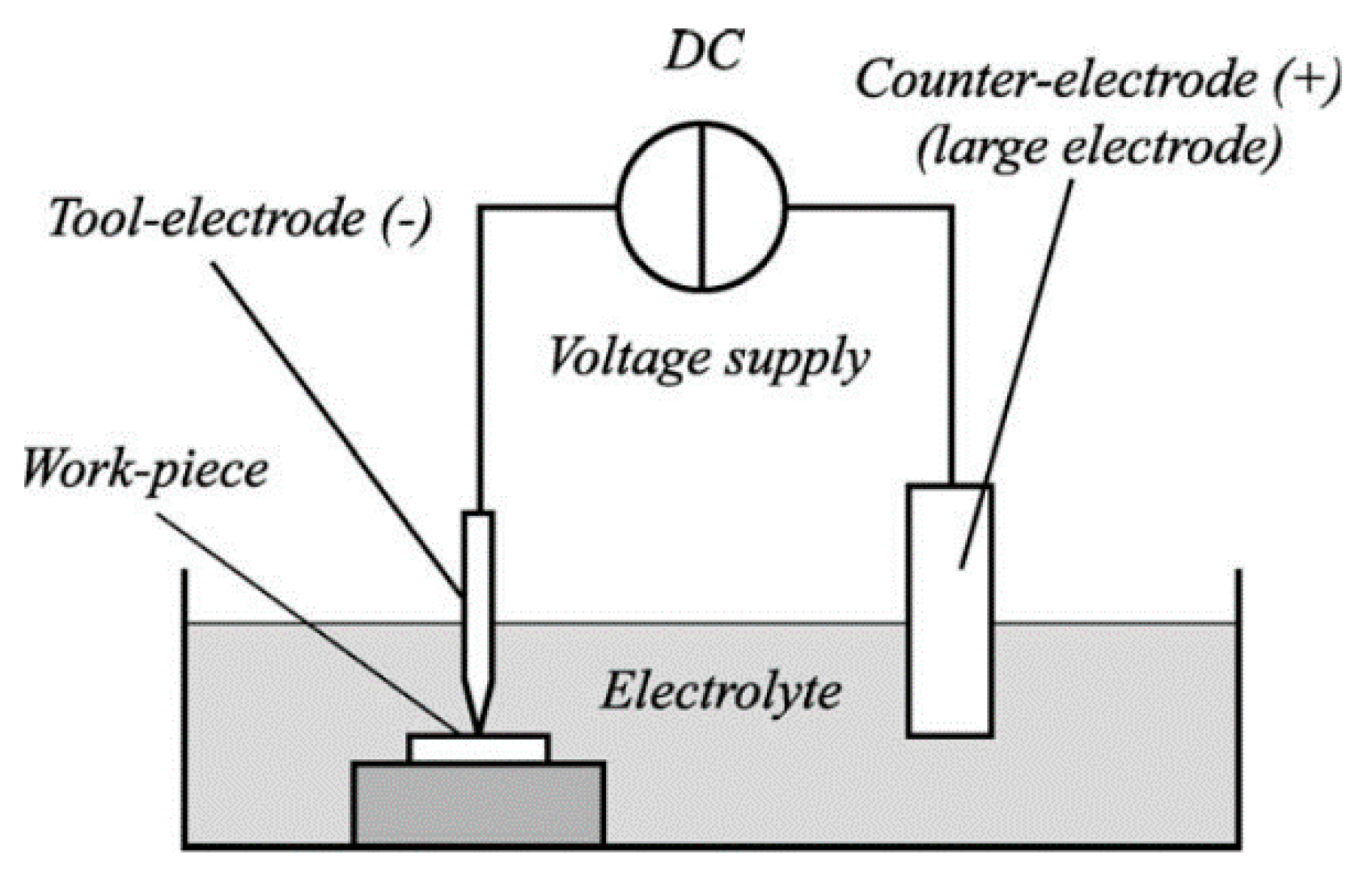
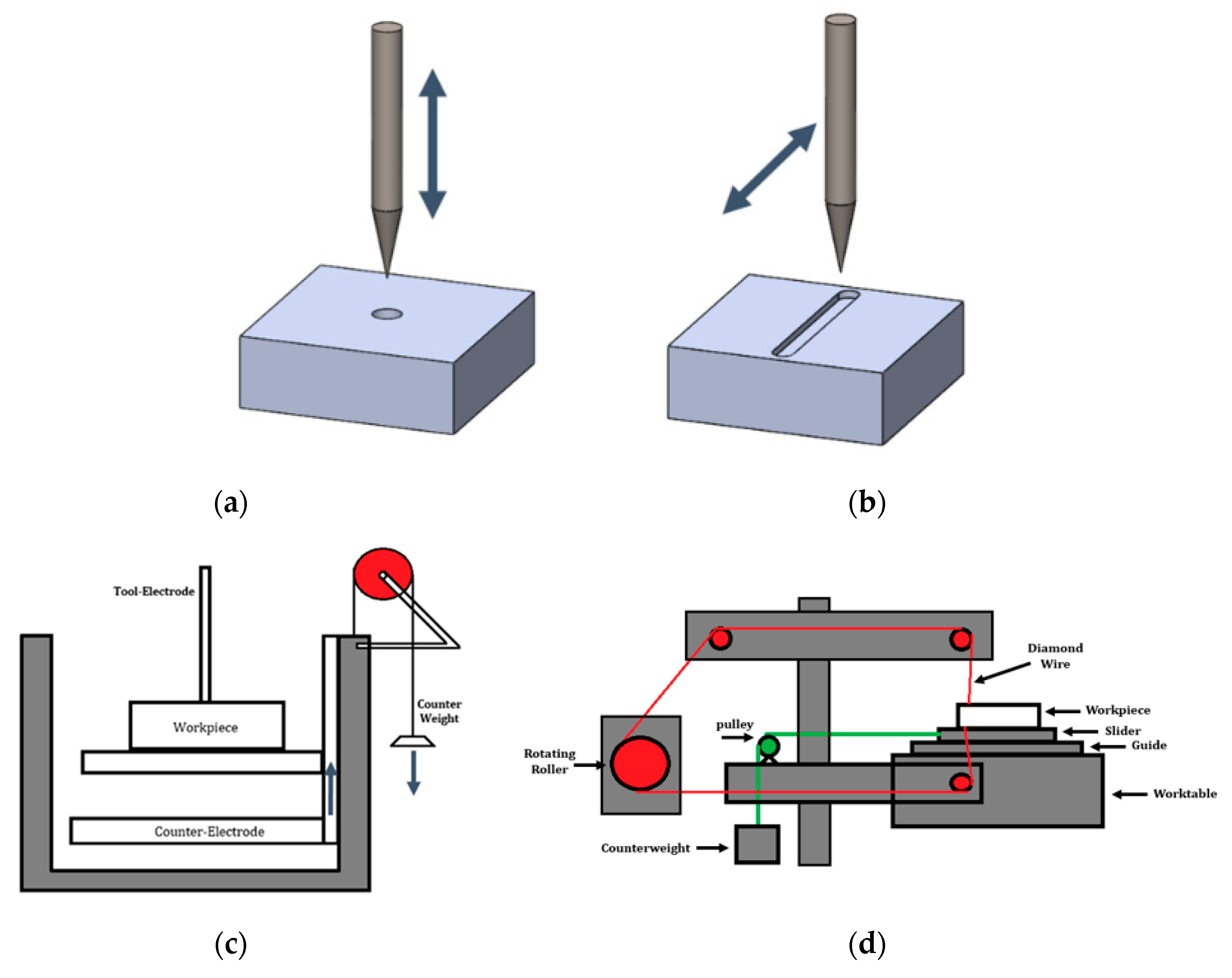
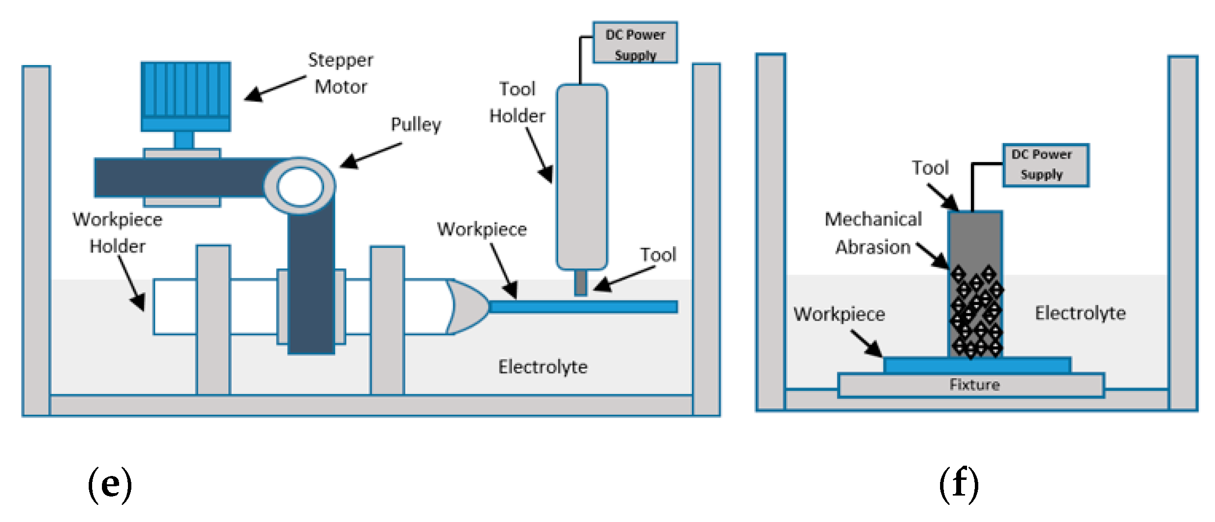
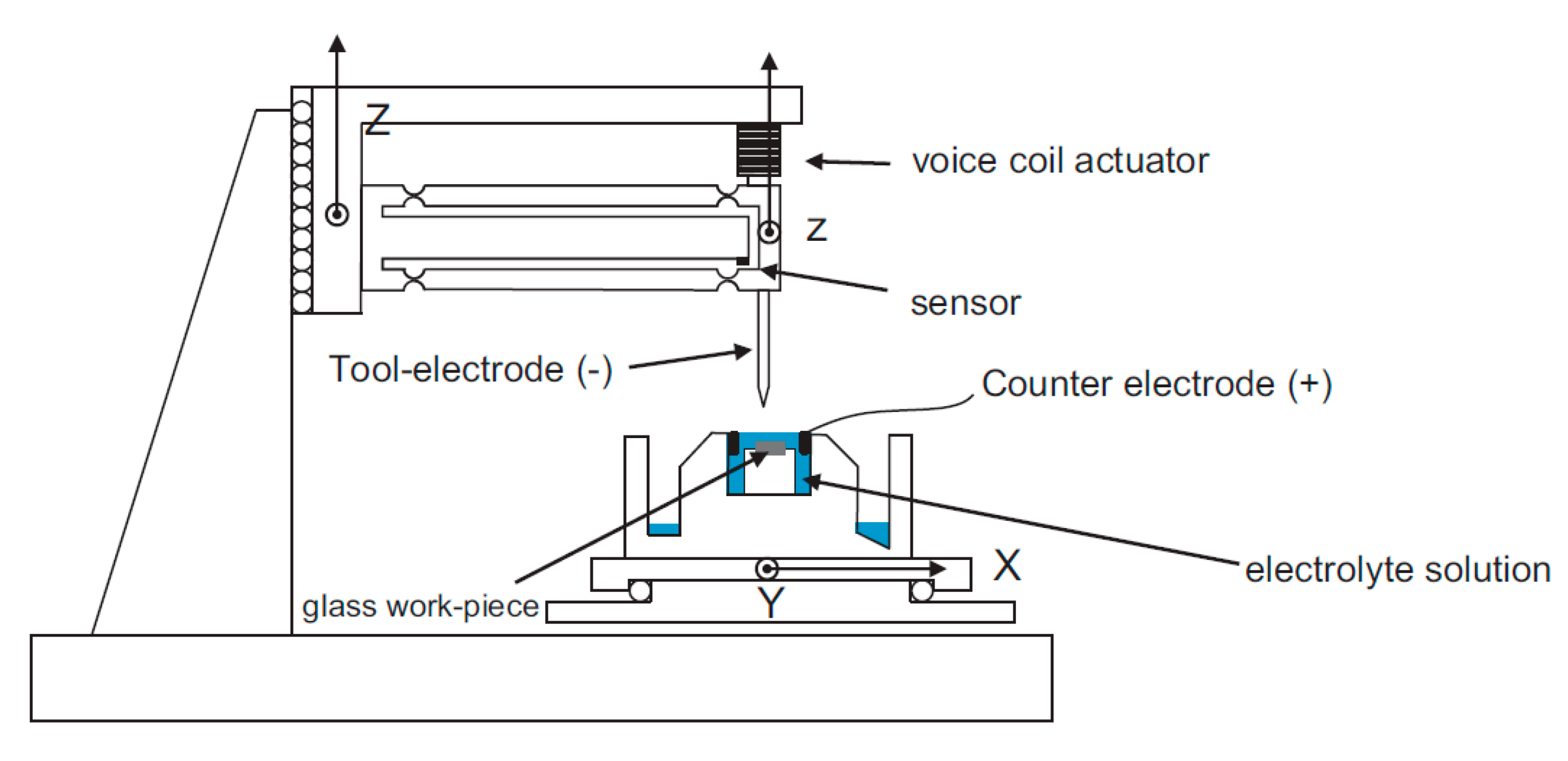
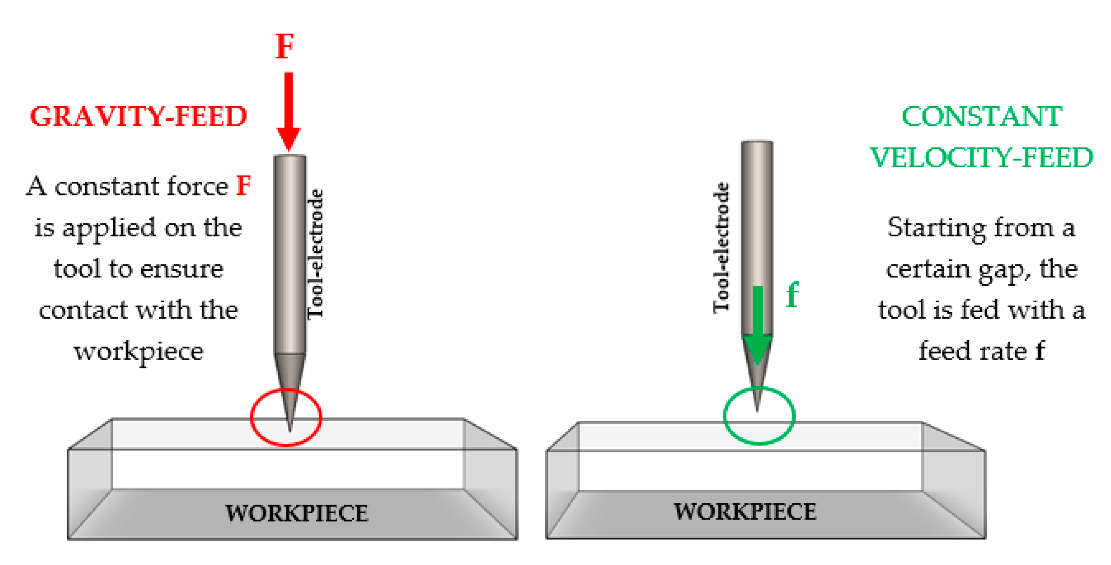
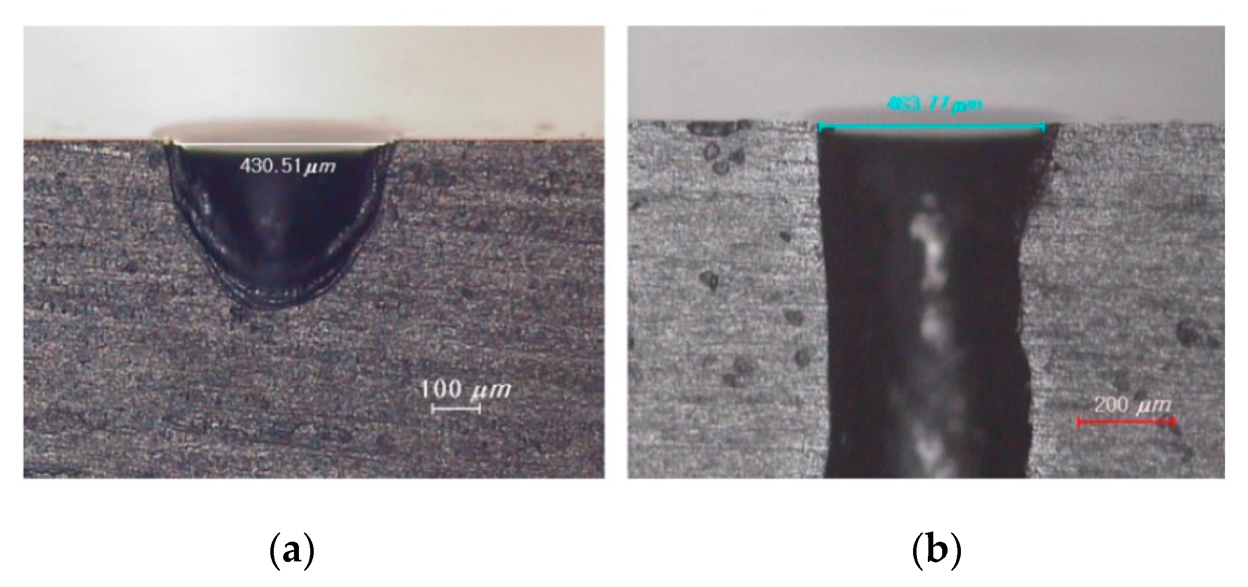
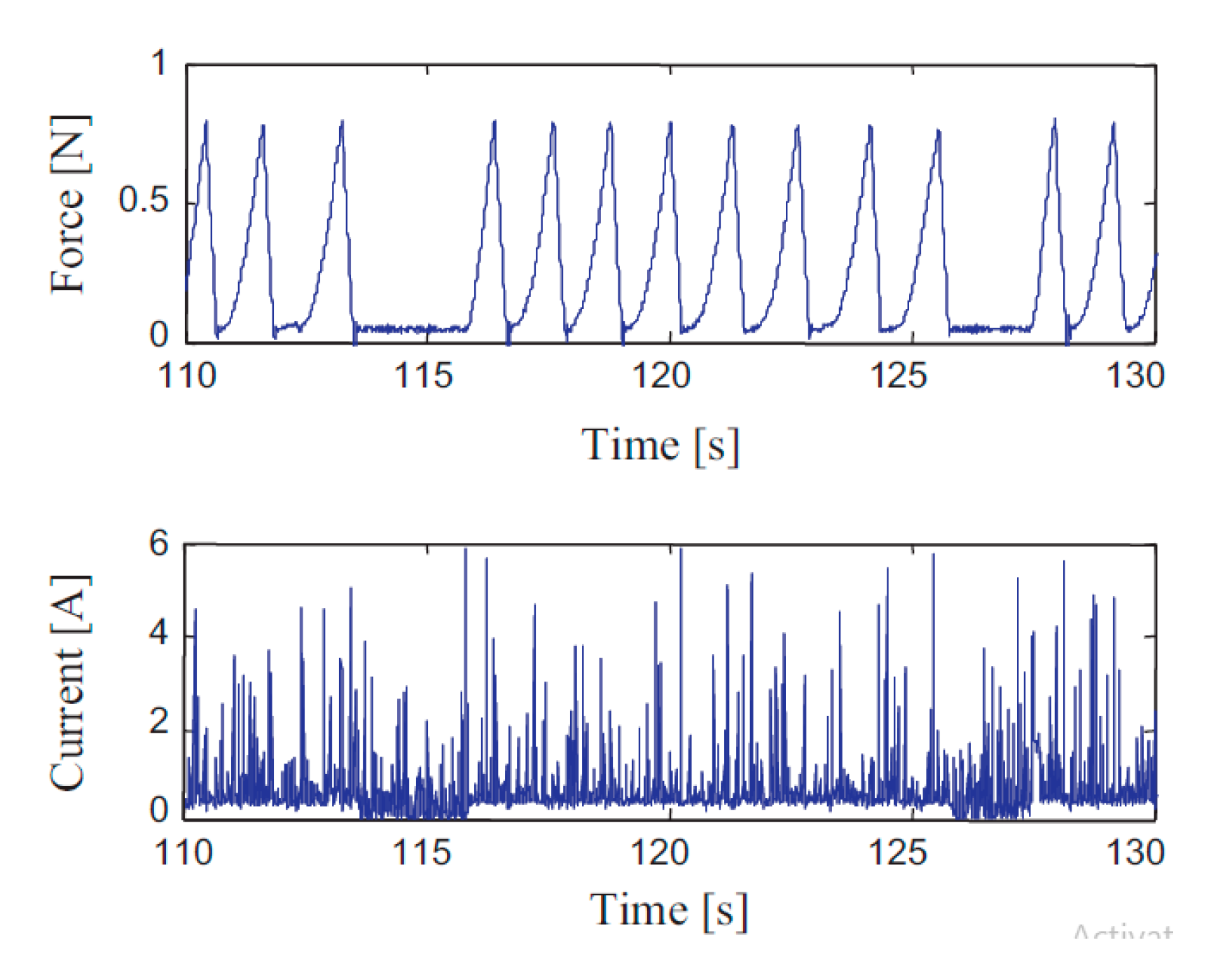
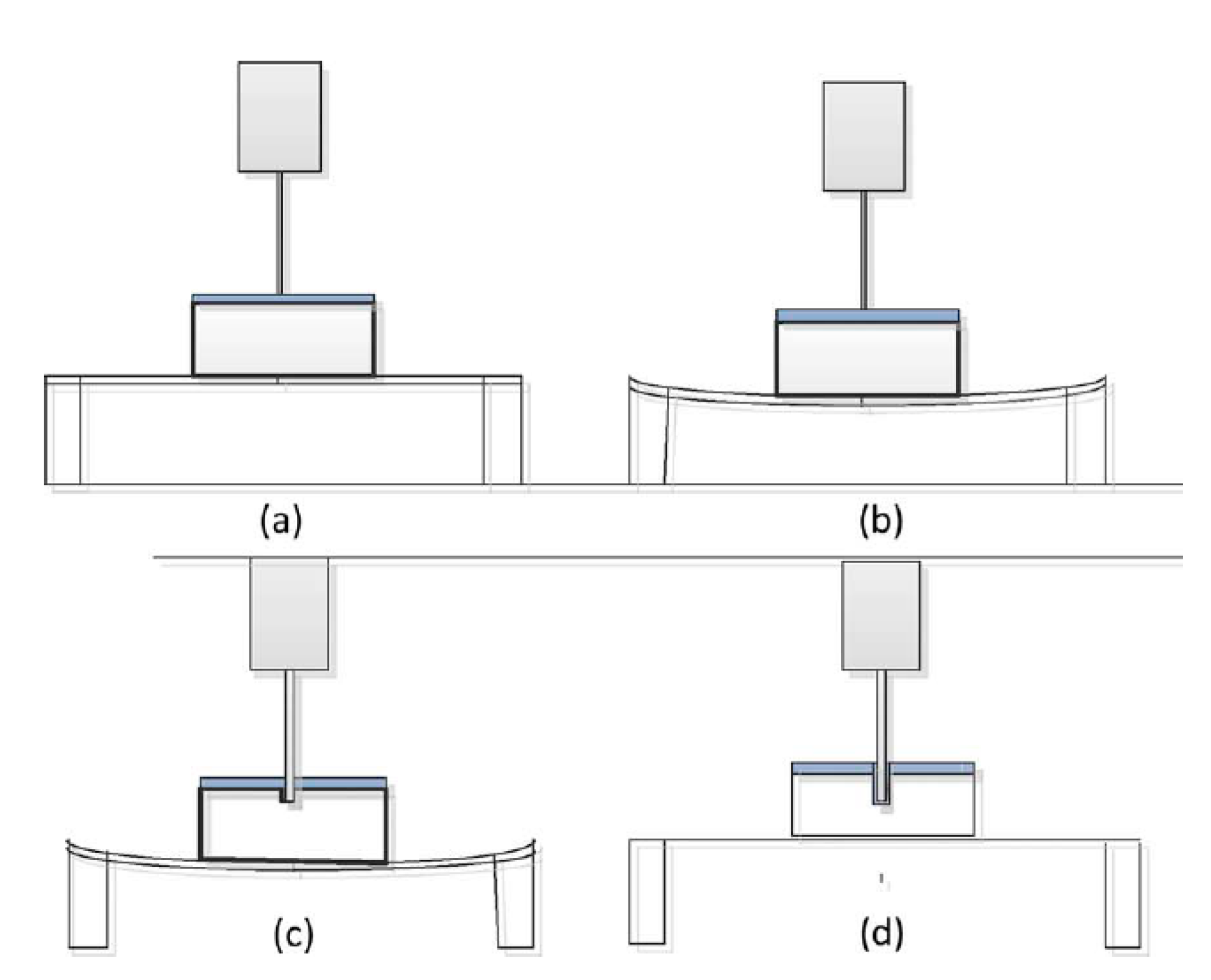
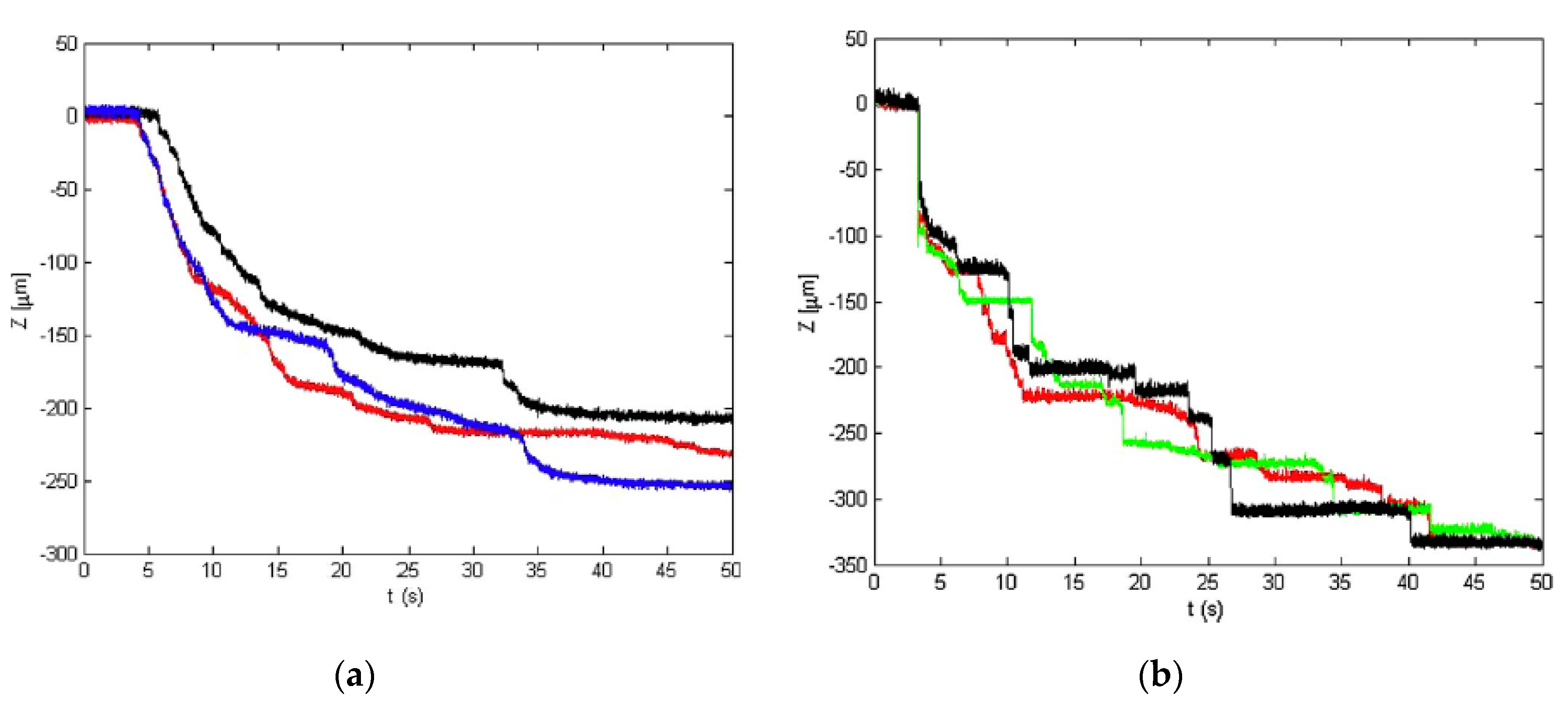
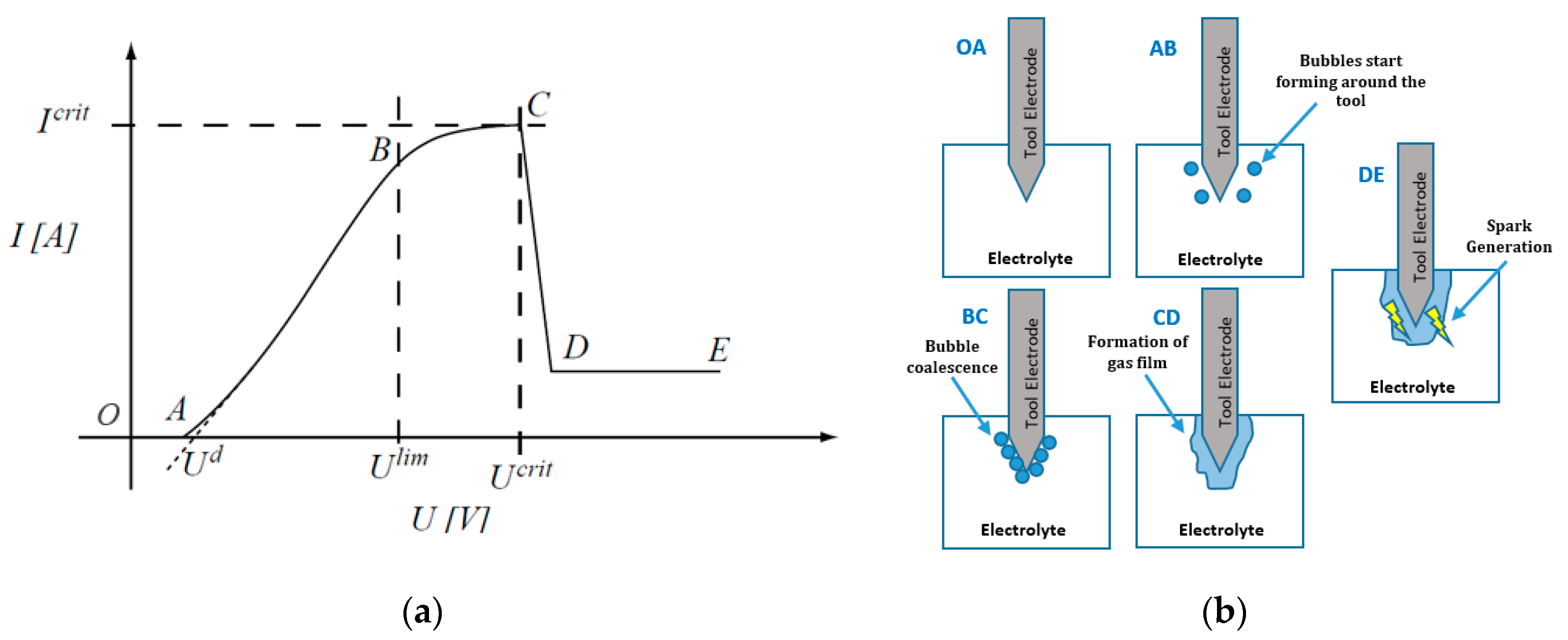
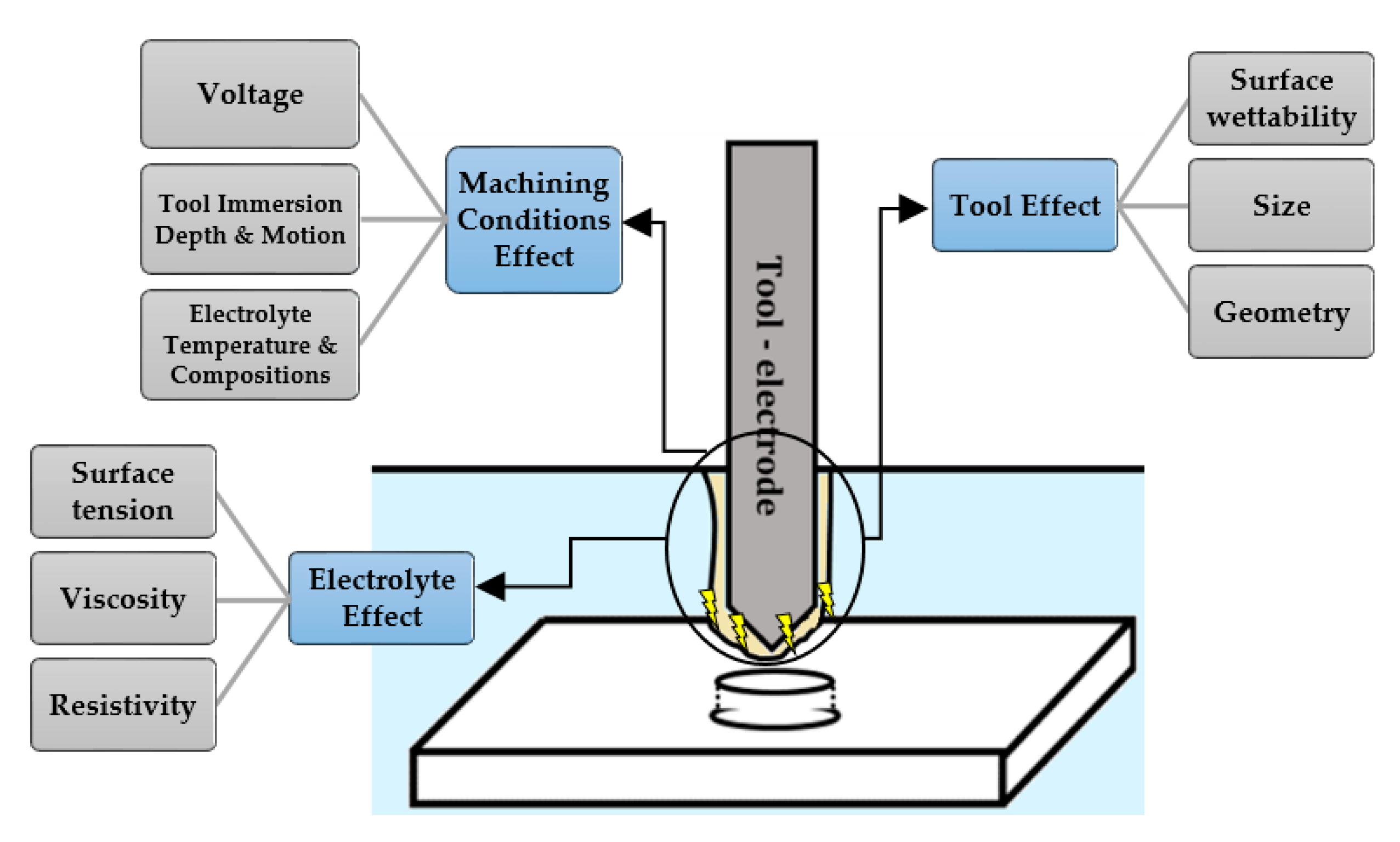
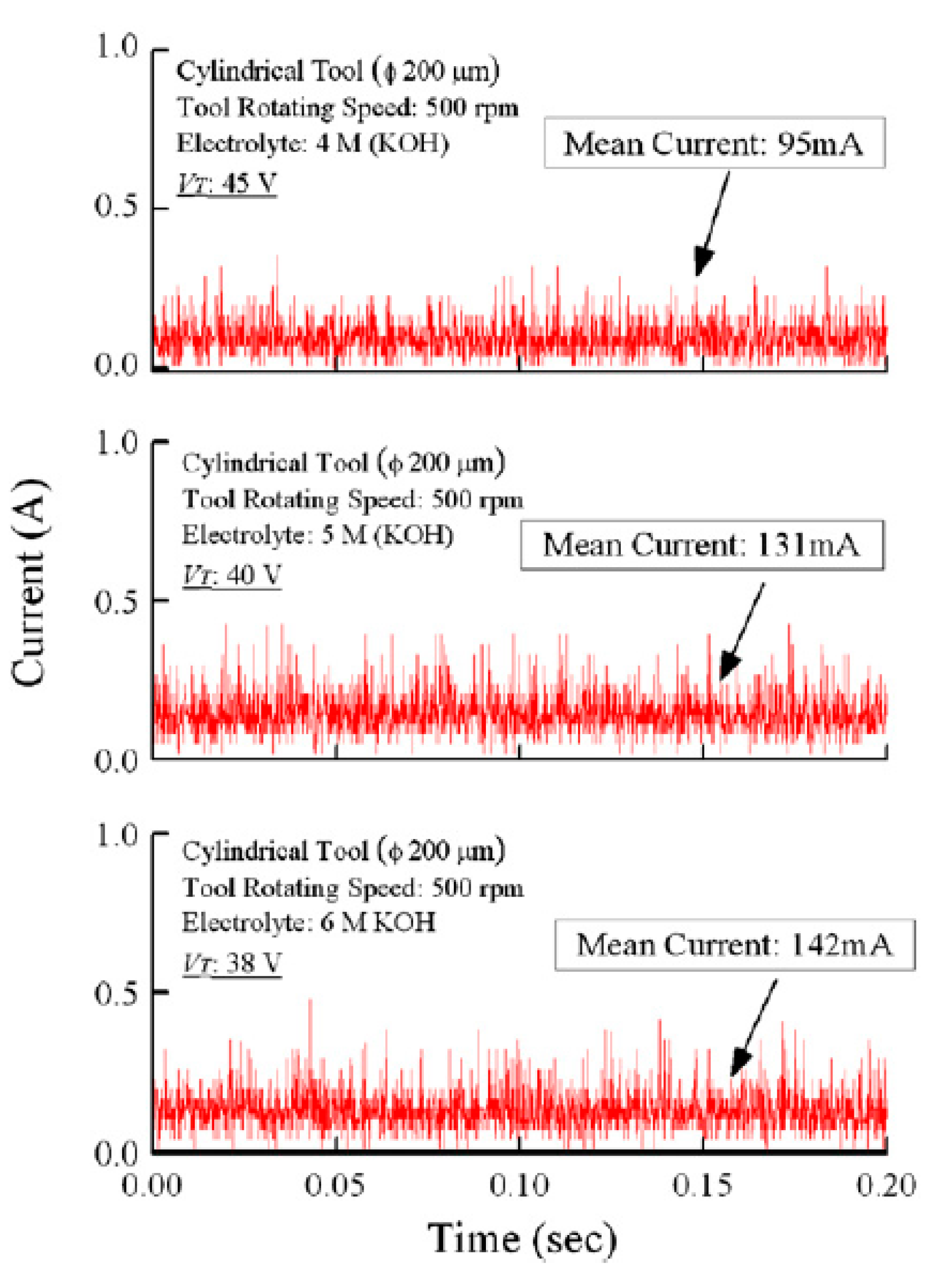
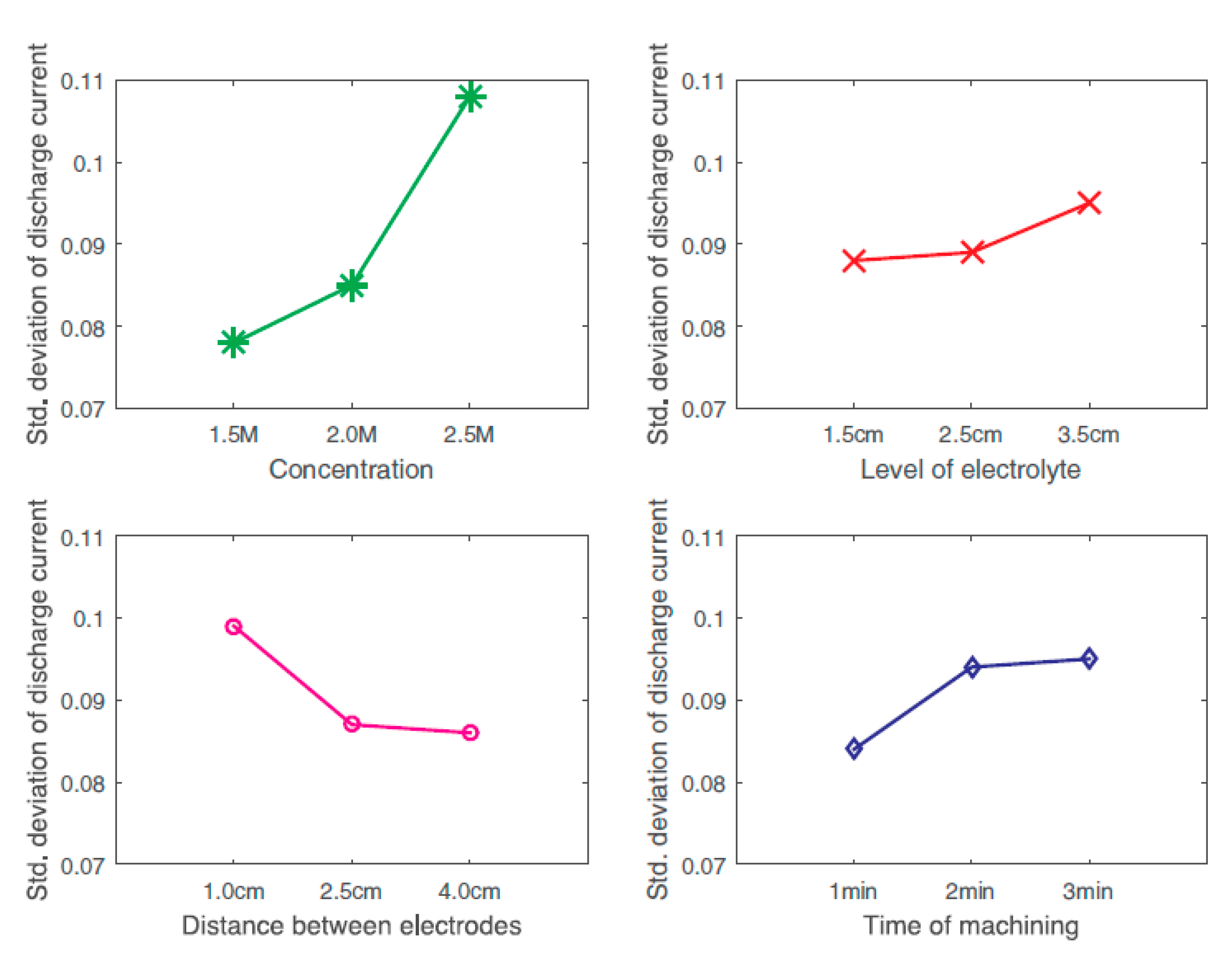
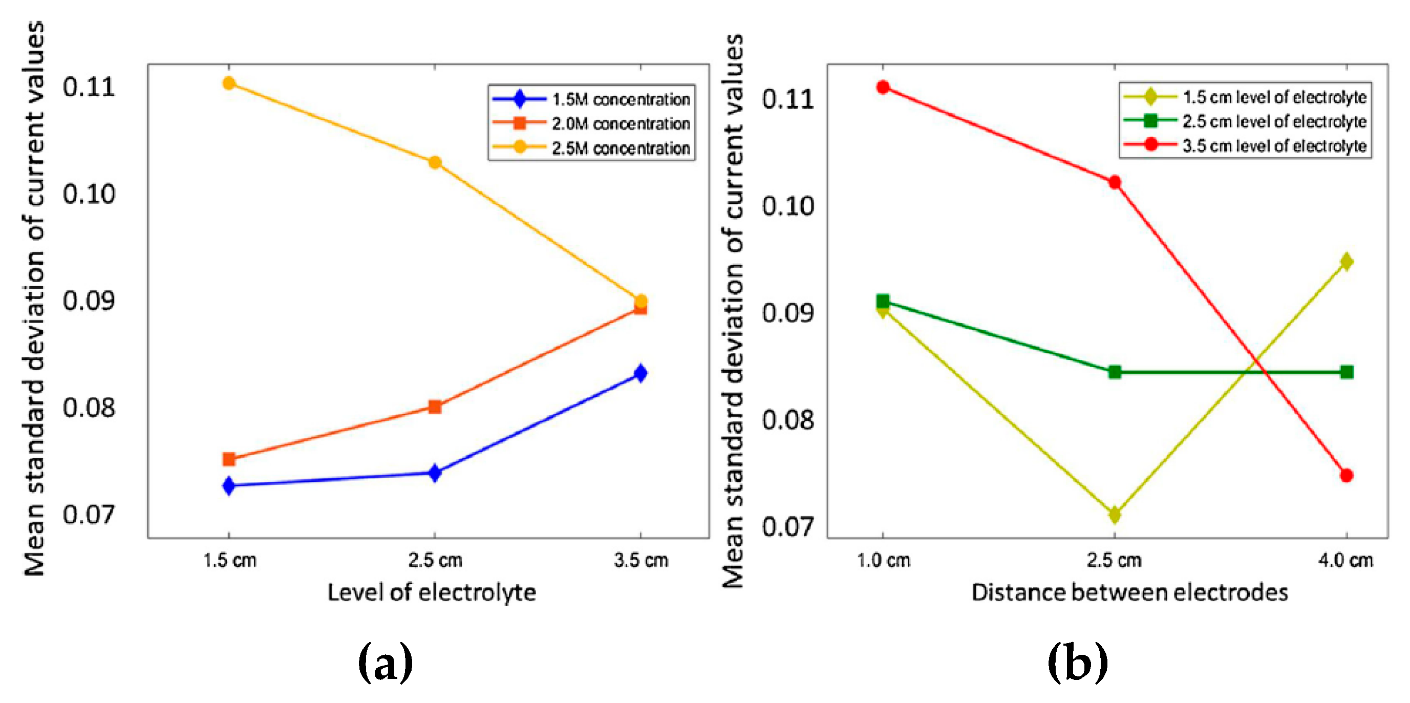
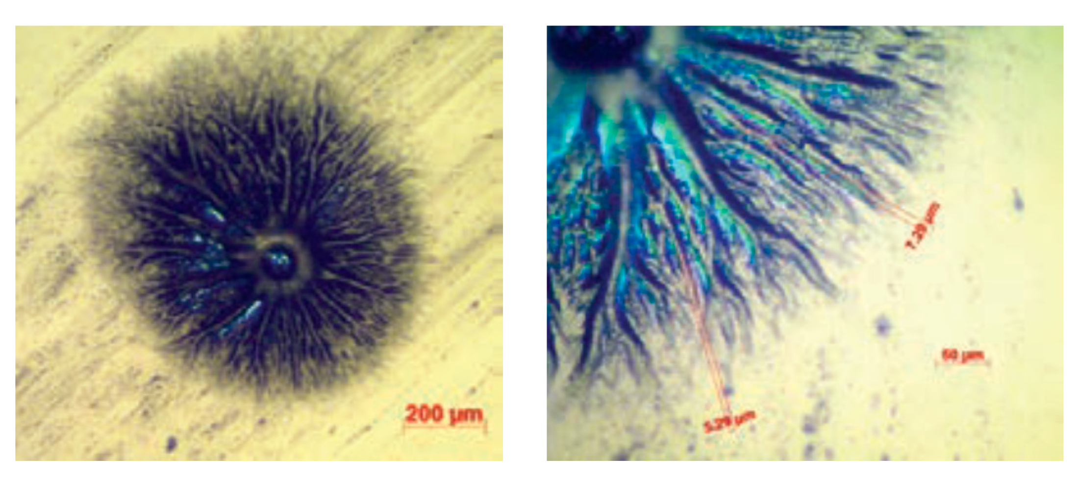
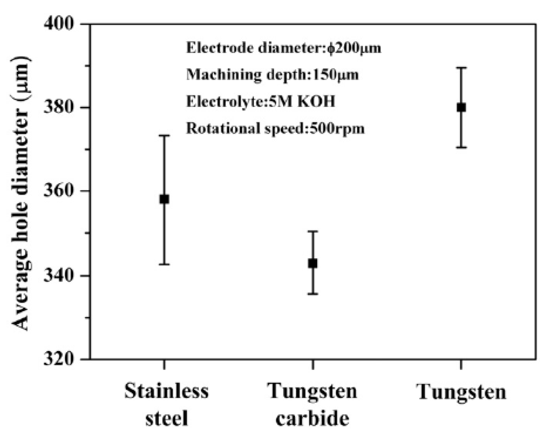
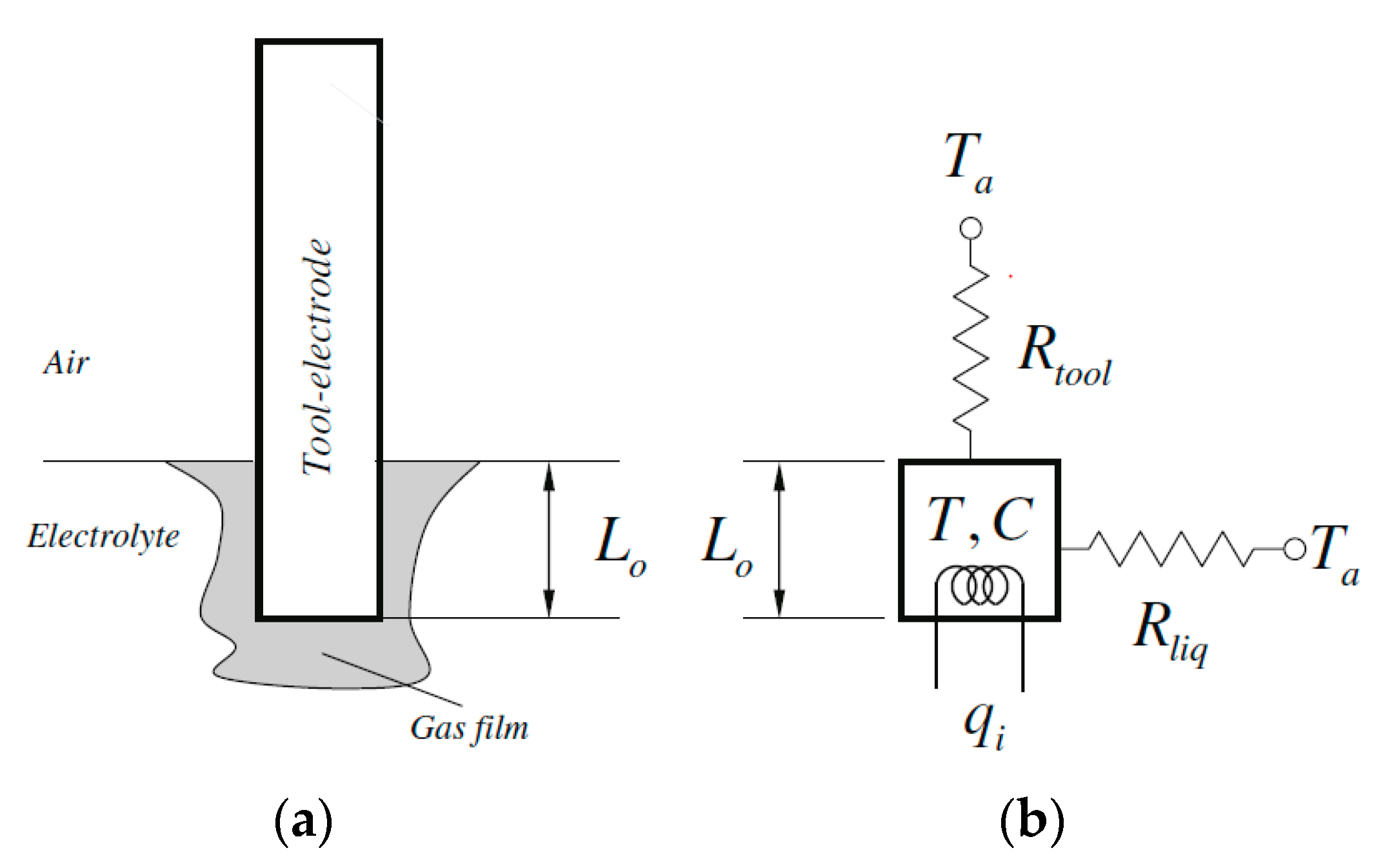
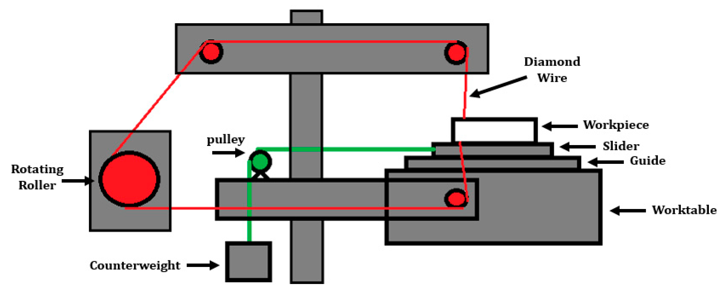
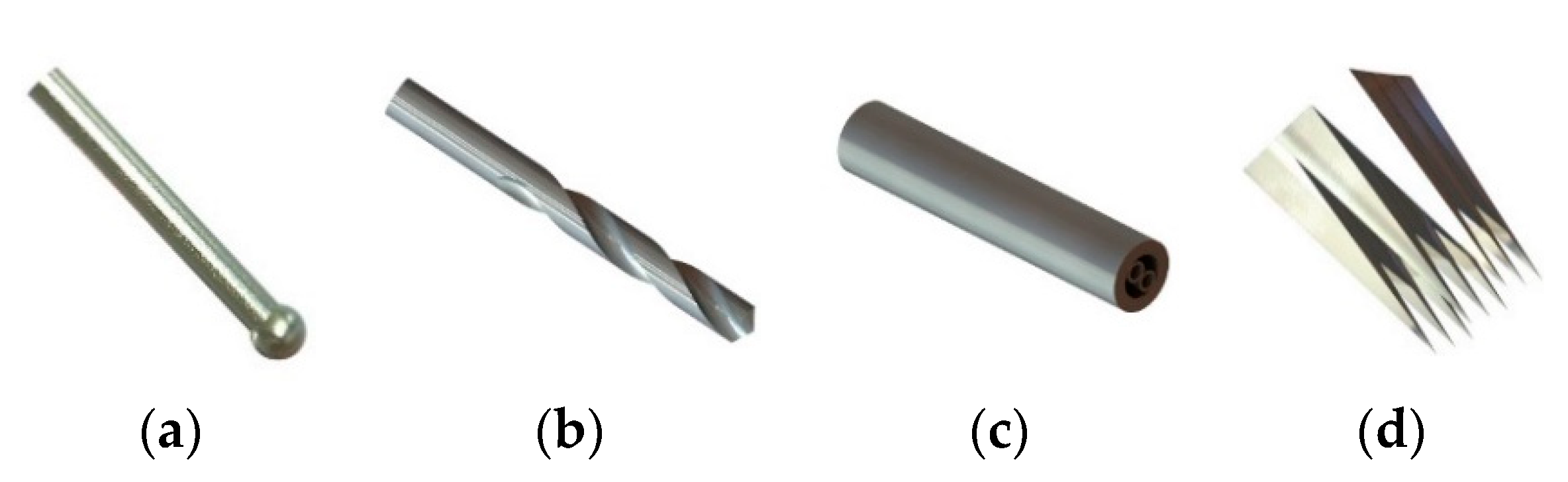
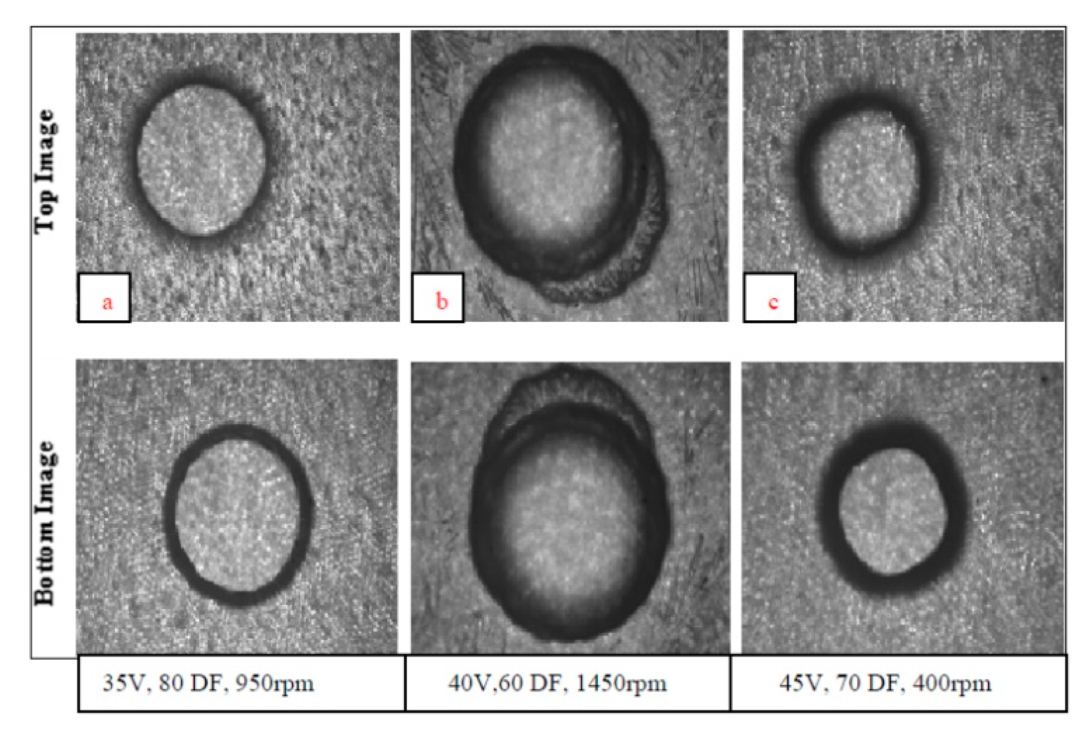
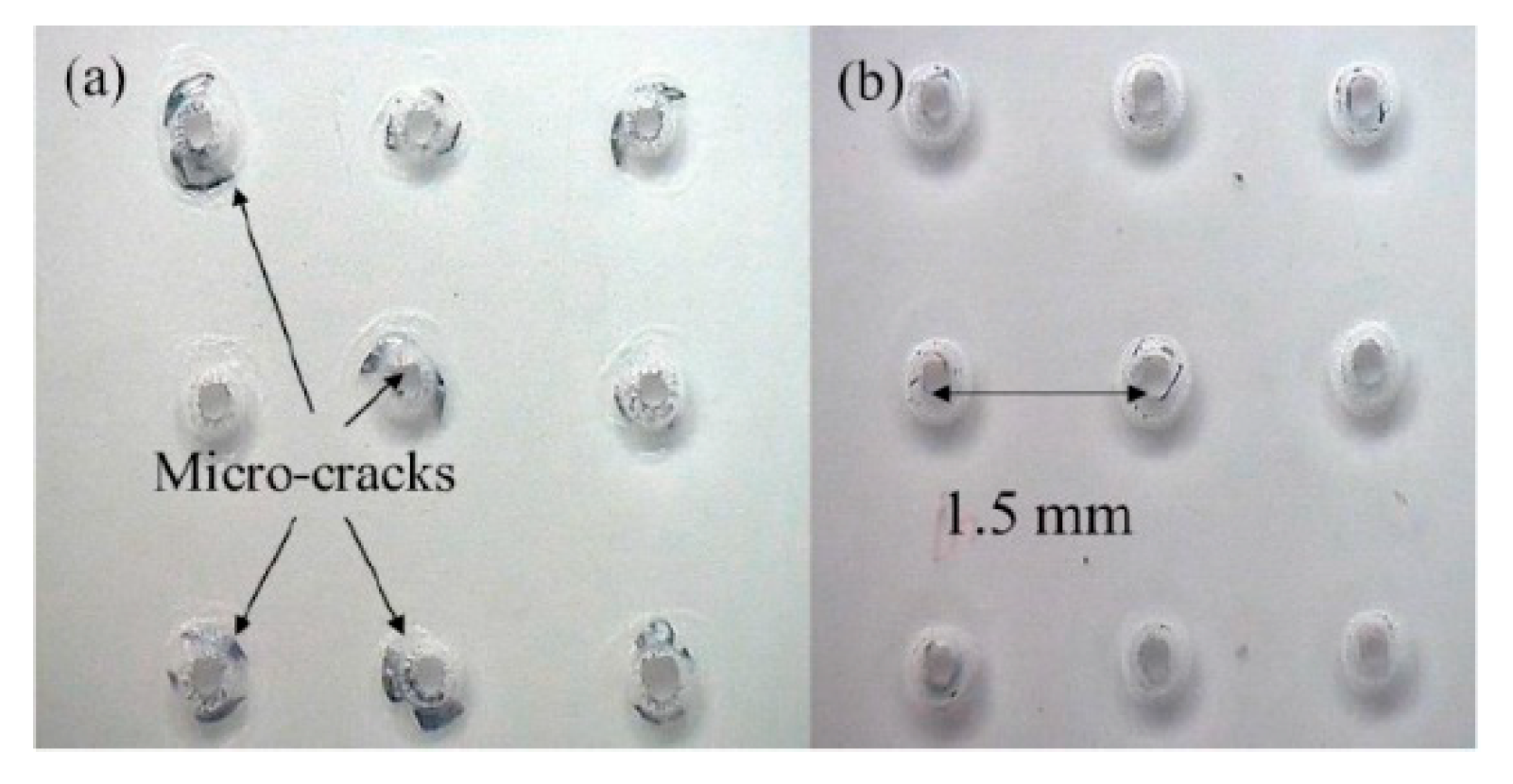
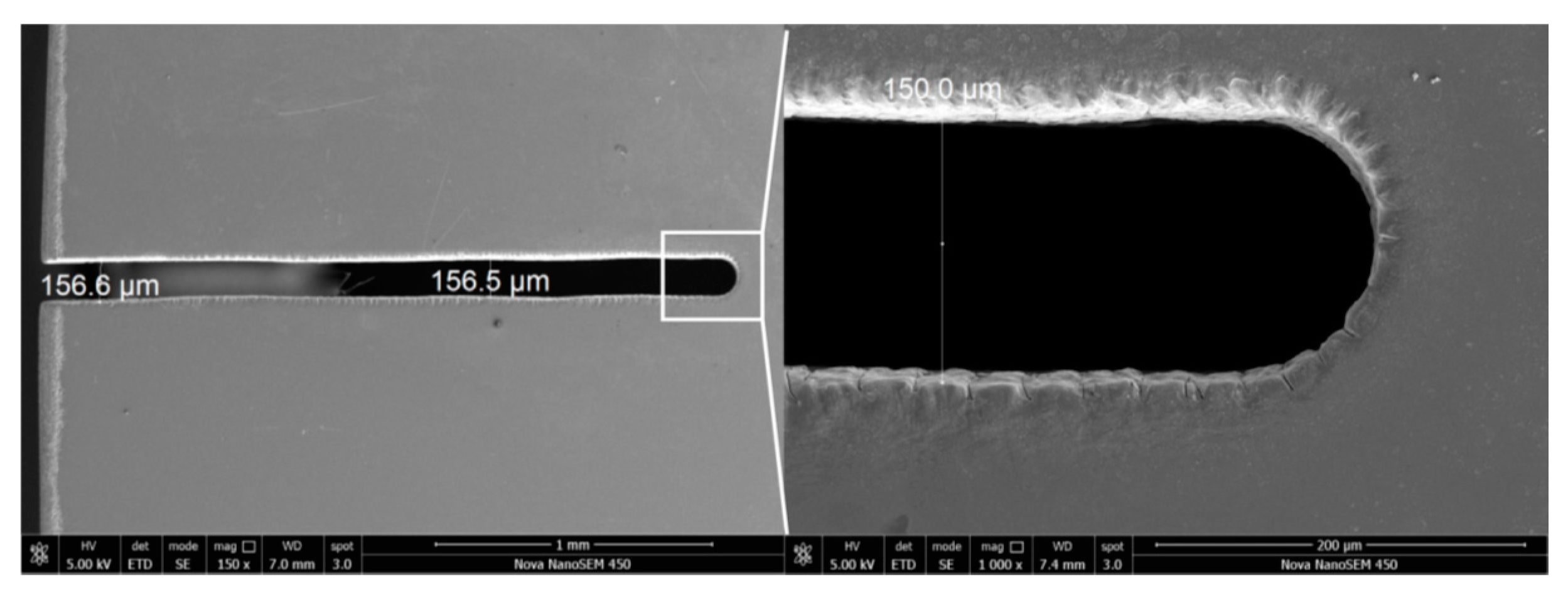
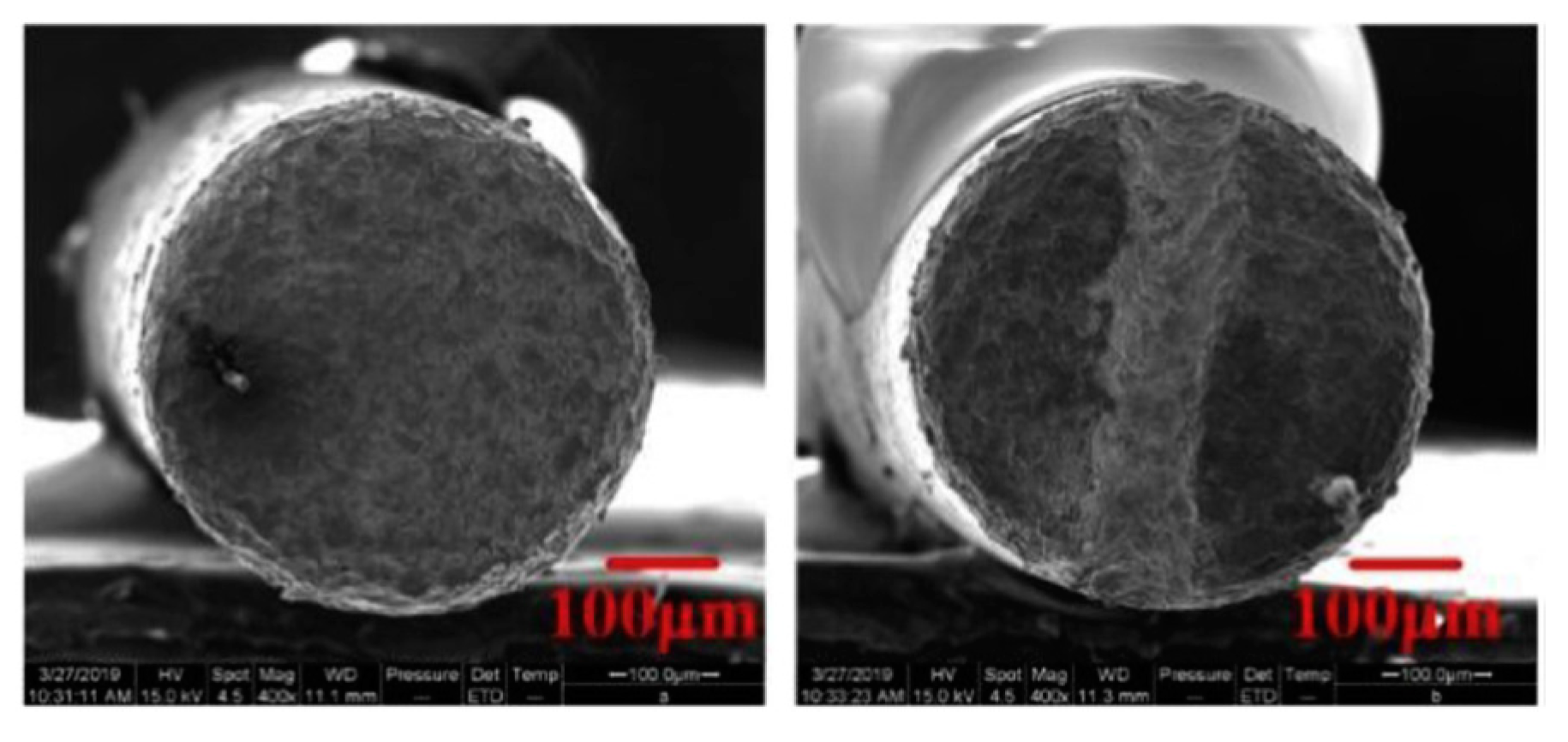
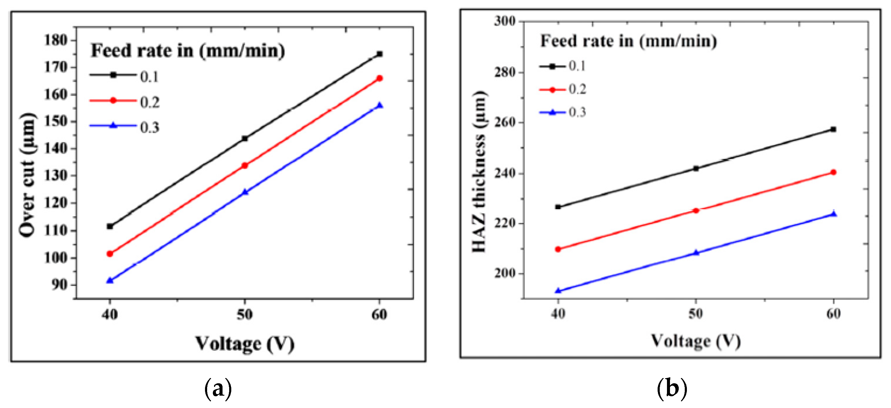
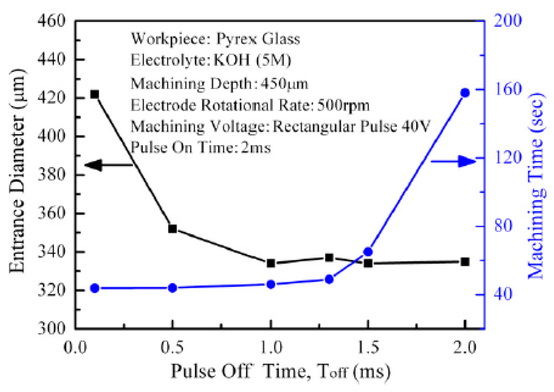
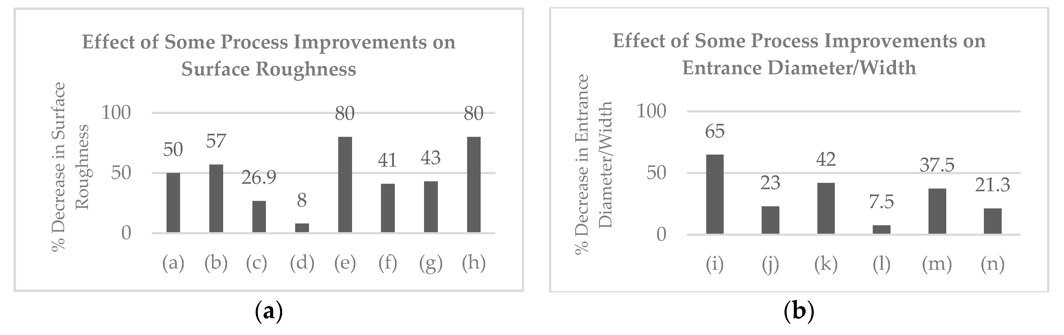
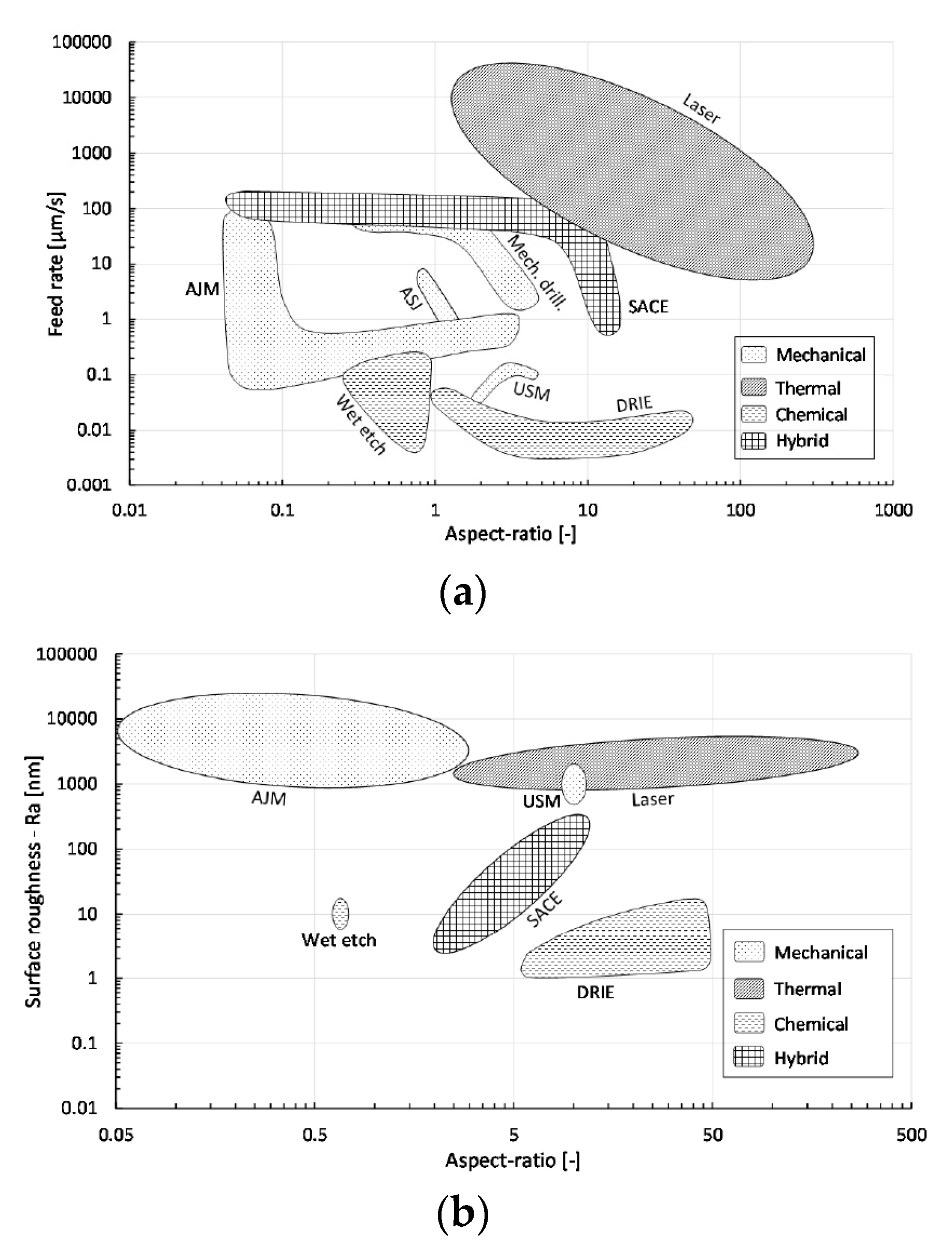
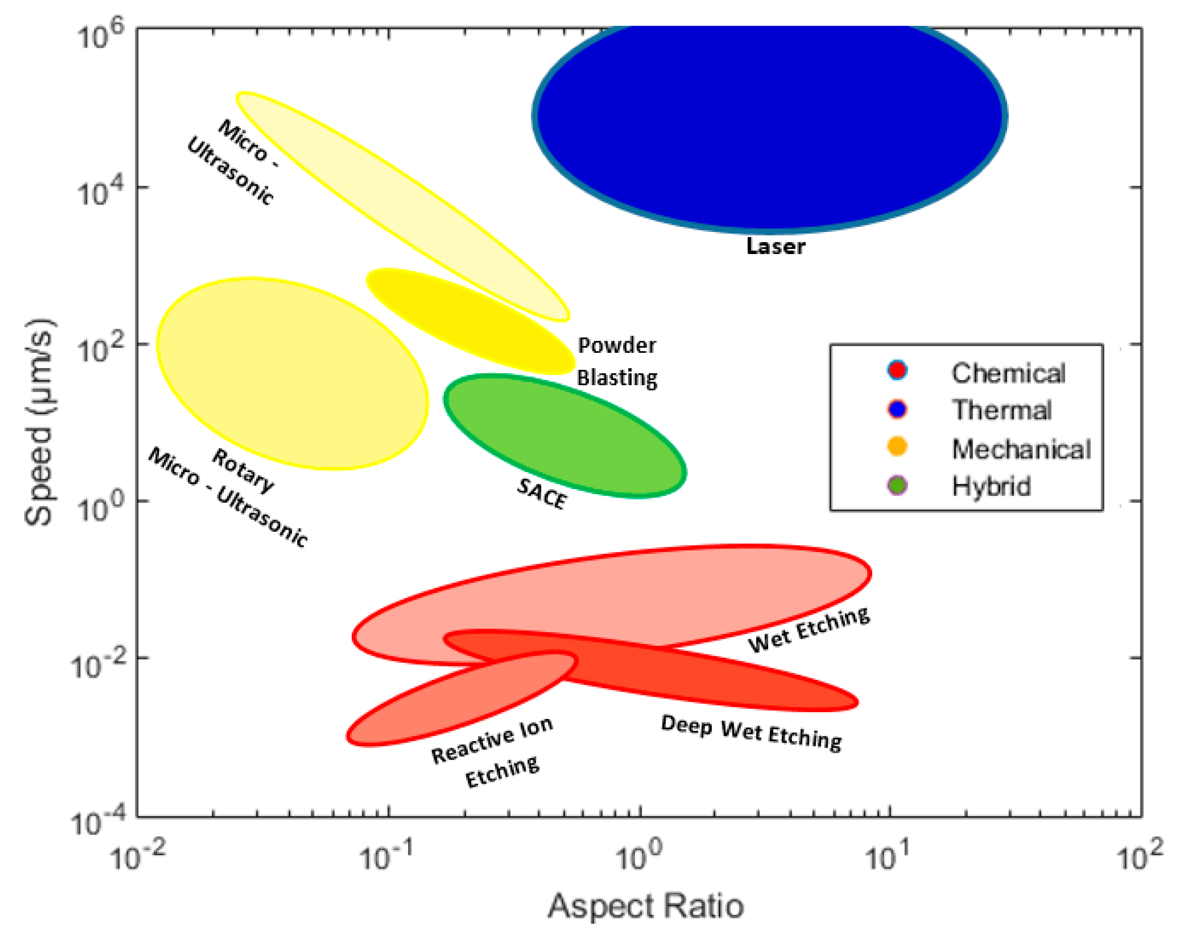
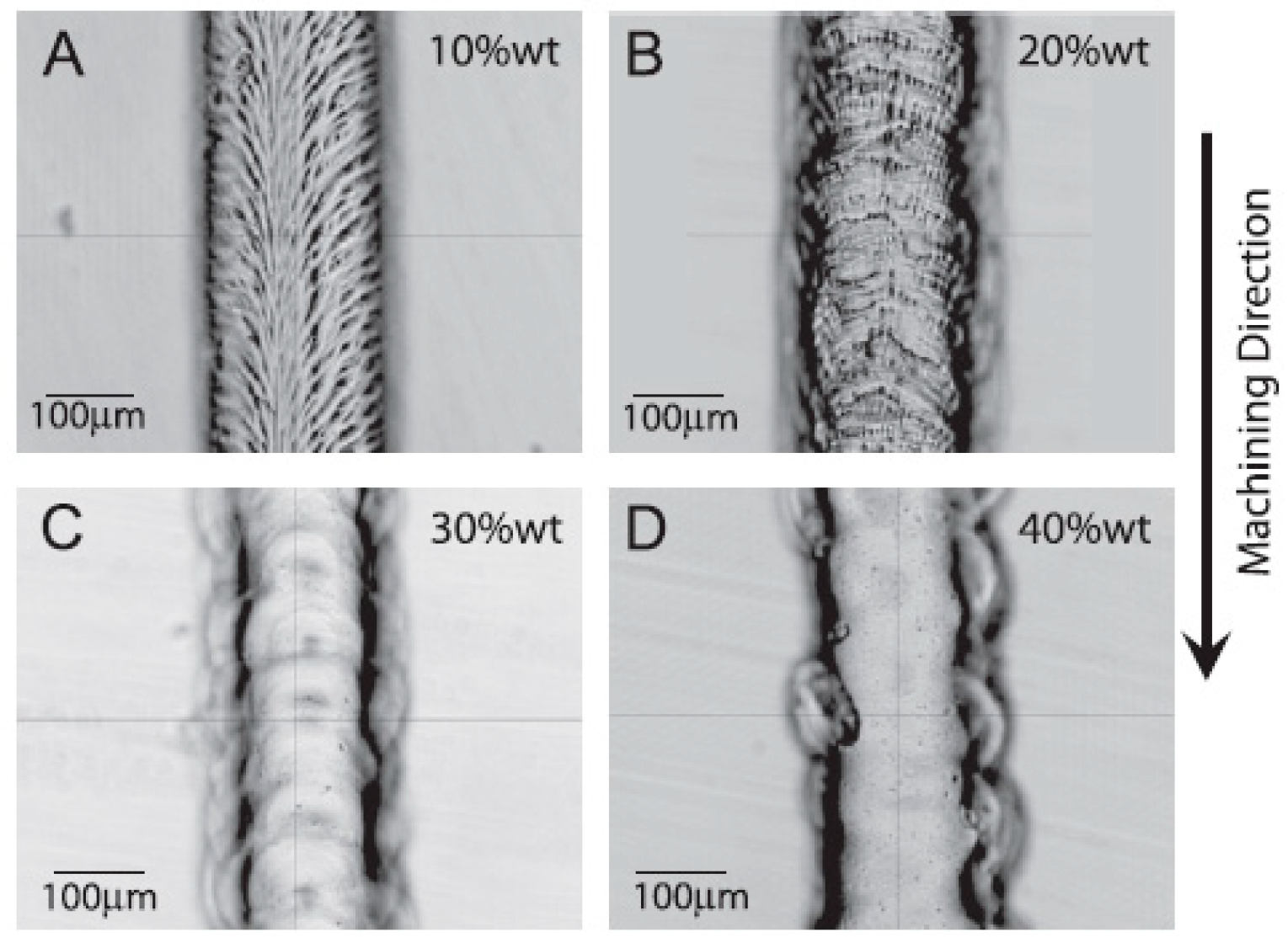
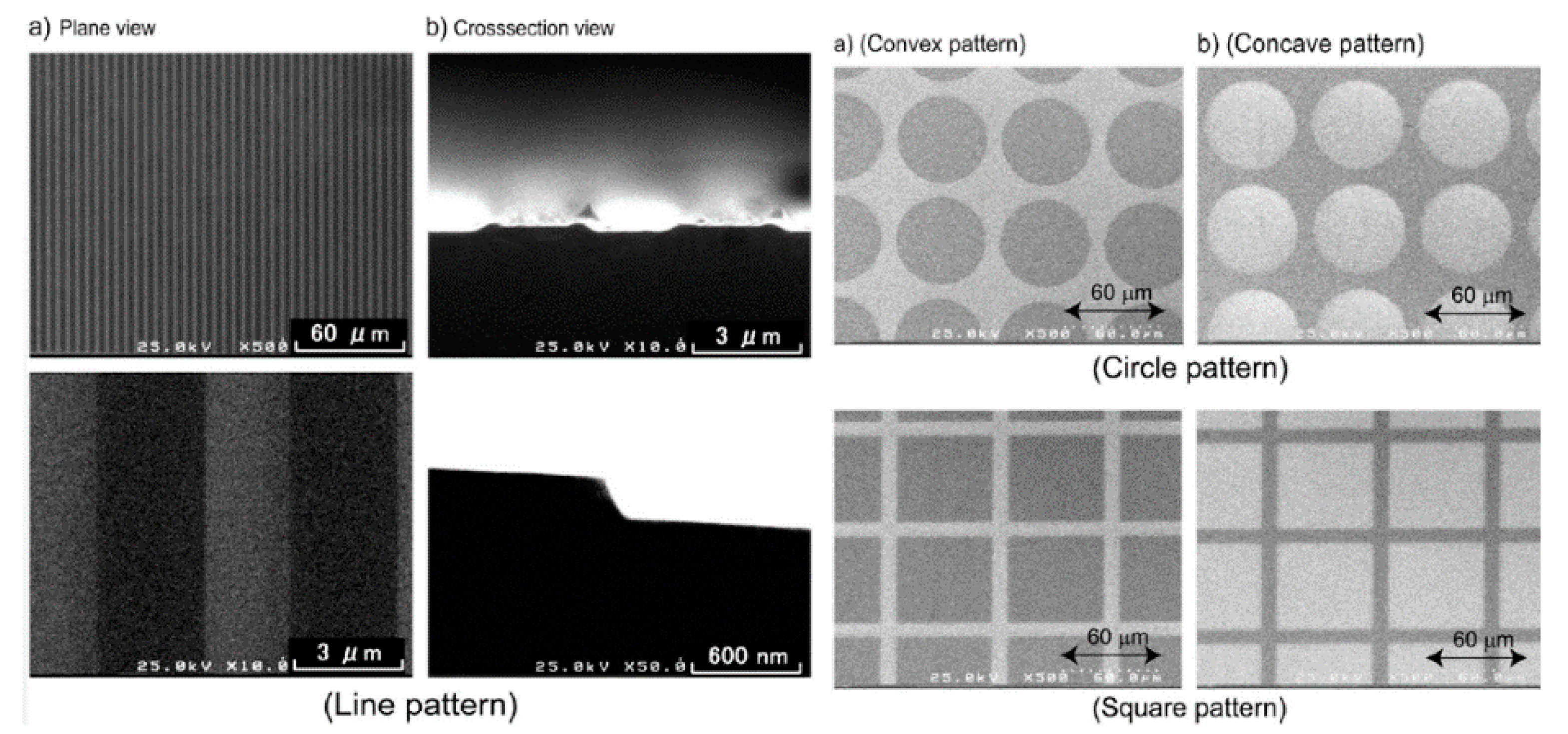
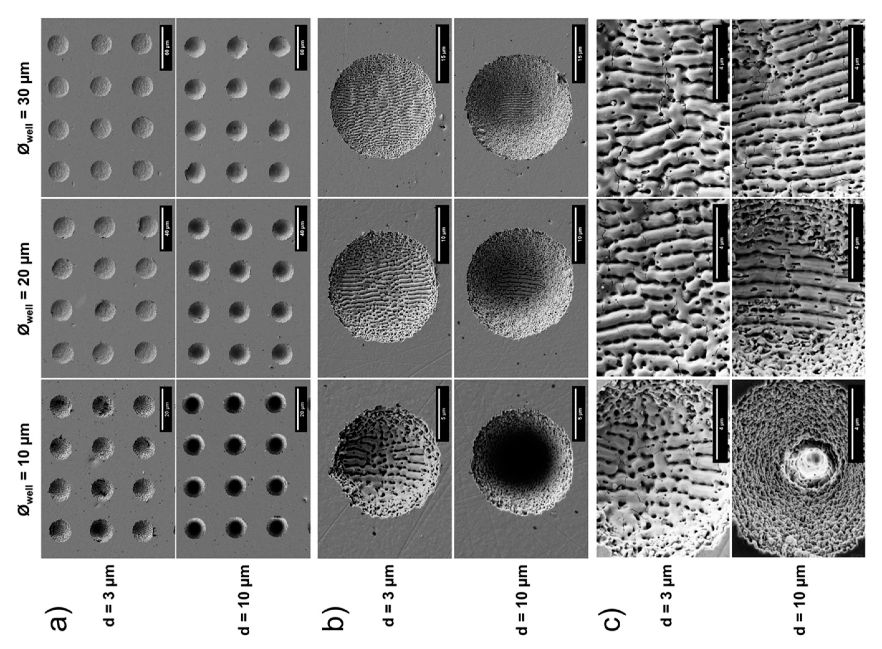
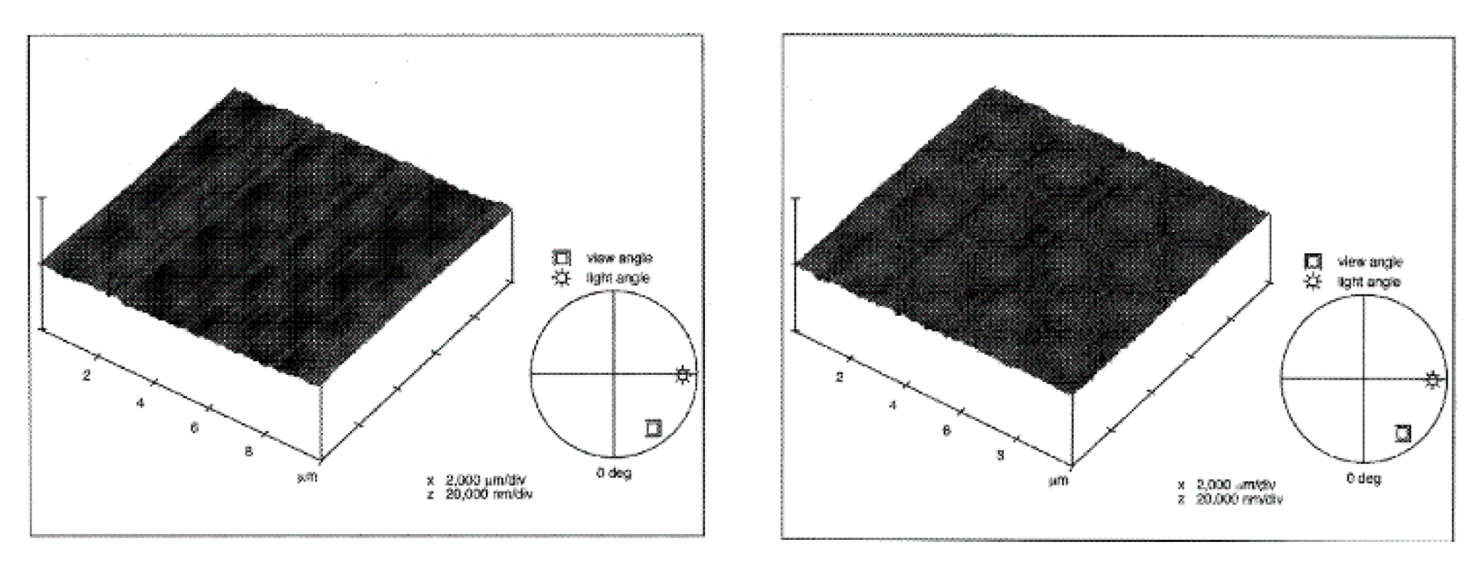
Table A1.
A list of popular glass micromachining techniques and their features for fabricating micro-channels in glass and ceramic materials.
Table A1.
A list of popular glass micromachining techniques and their features for fabricating micro-channels in glass and ceramic materials.
| Depth (µm) | Entrance Width (µm) | Depth to Width Ratio * | Speed Rate (µm/s) | References | |
|---|---|---|---|---|---|
| Chemical Methods | |||||
| Deep Wet Etching | 33 | 7 | 4.7 | 0.0038 | [144] |
| Wet Etching | 329 | 420 | 0.78 | 0.133 | [145] |
| Wet Etching | 20 | 220 | 0.09 | 0.085 | [146] |
| Deep Wet Etching | 60 | 250 | 0.24 | 0.0167 | [147] |
| Wet Etching | 150 | 30 | 5 | 0.027 | [148] |
| Deep Reactive Ion Etching | 250 | 600 | 0.42 | 0.008 | [149] |
| Wet Etching | 102 | 500 | 0.204 | 0.054 | [150] |
| Wet Etching | 70 | 12 | 5.8 | 0.011 | [151] |
| Wet Etching | 45 | 100 | 0.45 | 0.167 | [152] |
| Reactive Ion Etching | 47 | 120 | 0.4 | 0.0057 | [153] |
| Reactive Ion Etching | 4.5 | 39 | 0.1 | 0.0019 | [154] |
| Wet Etching | 150 | 30 | 5 | 0.03 | [155] |
| Thermal Methods | |||||
| CO2 Laser | 1561.2 | 305.75 | 5 | 5000 | [156] |
| LIPAA | 200 | 87 | 2.3 | 800000 | [134] |
| IR femtosecond laser | 30 | 30 | 1 | 1000000 | [116] |
| SLE | 35 | 2 | 17.5 | 200000 | [120] |
| Nd: YVO4 Laser | 11 | 8 | 1.375 | 50000 | [157] |
| Nd: YAG laser | 958 | 200 | 4.79 | 55800 | [158] |
| Picosecond (PS) Laser | 762 | 72 | 10 | 75000 | [139] |
| NIR femtosecond Laser | 69 | 26 | 2.65 | 5000 | [115] |
| LIBWE | 525 | 24 | 21.88 | 150000 | [159] |
| Fiber Laser | 373.15 | 395.28 | 0.94 | 7000 | [160] |
| Mechanical Methods | |||||
| Rotary Micro-Ultrasonic | 10 | 600 | 0.0167 | 333 | [161] |
| Micro-Ultrasonic | 79.167 | 695 | 0.11 | 422.5 | [162] |
| Micro-Ultrasonic | 170 | 375 | 0.4 | 62.6 | [163] |
| Powder Blasting | 310 | 700 | 0.4 | 400 | [164] |
| Powder Blasting | 9.98 | 318.3 | 0.03 | 100000 | [165] |
| Rotary Micro-Ultrasonic | 12.5 | 500 | 0.025 | 8.33 | [166] |
| Rotary Micro-Ultrasonic | 100 | 800 | 0.125 | 16.67 | [167] |
| Ball End Milling | 20 | 175 | 0.1 | 8 | [168] |
| Hybrid Methods | |||||
| SACE | 256 | 520 | 0.5 | 10 | [67] |
| SACE | 135 | 510 | 0.3 | 200 | [44] |
| SACE | 118 | 478.4 | 0.2 | 16.67 | [169] |
| SACE | 240 | 800 | 0.3 | 25 | [170] |
| SACE | 100 | 300 | 0.33 | 25 | [171] |
| SACE | 130 | 129.4 | 1 | 2 | [172] |
| SACE | 150 | 135.9 | 1.1 | 2 | [172] |
| SACE | 260 | 500 | 0.52 | 10 | [118] |
* Depth per Pass
References
- Mills, D.; Kreouzis, T.; Sapelkin, A.; Unal, B.; Zyuzikov, N.; Kolasinski, K.W. Surface Texturing of Si, porous Si, and TiO2 bylaser ablation. Appl. Surf. Sci. 2007, 253, 6575–6579. [Google Scholar] [CrossRef]
- Zhao, J.; Wang, A.; Green, M.; Ferrazza, F. 19.8% efficient honeycomb textured multicrystalline and 24.4% monocrystalline silicon solar cells. Appl. Phys. Lett. 1998, 73, 1991–1993. [Google Scholar] [CrossRef]
- Goel, M. Recent developments in electroceramics: MEMS applications for energy and environment. Ceram. Int. 2004, 30, 1147–1154. [Google Scholar] [CrossRef]
- Sinton, D. Energy: The microfluidic frontier. Lab Chip 2014, 14, 3127–3134. [Google Scholar] [CrossRef] [PubMed]
- Abou Ziki, J.D. Spark Assisted Chemical Engraving: A Novel Approach for Quantifying the Machining Zone Parameters Using Drilling Forces; Concordia University: Montreal, QC, Canada, 2014. [Google Scholar]
- Wüthrich, R.; Fascio, V. Machining of non-conducting materials using electrochemical discharge phenomenon—An overview. Int. J. Mach. Tools Manuf. 2005, 45, 1095–1108. [Google Scholar] [CrossRef]
- Wüthrich, R.; Abou Ziki, J.D. Micromachining Using Electrochemical Discharge Phenomenon: Fundamentals and Application of Spark Assisted Chemical Engraving (Micro and Nano Technologies), 2nd ed.; Elsevier: Amsterdam, The Netherlands, 2015. [Google Scholar]
- Allesu, K.; Ghosh, A.; Muju, M.K. A Preliminary qualitative approach of a proposed mechanism of material removal in electrical machining of glass. Eur. J. Mech. Eng. 1992, 36, 202–207. [Google Scholar]
- Kubota, M. Characteristics of ECDM. In Proceedings of the International Conference on Production Engineering, Tokyo, Japan, 26–29 August 1974. [Google Scholar]
- Tandon, S.; Jain, V.; Kumar, P.; Rajurkar, K. Investigations into machining of composites. Precis. Eng. 1990, 12, 227–238. [Google Scholar] [CrossRef]
- Langen, H.; Fascio, V.; Wüthrich, R.; Viquerat, D. Three-dimensional structuring of pyrex glass devices—trajectory control. In Proceedings of the International Conference of the European Society for Precision Engineering and Nanotechnology (EUSPEN) 2, Eindhoven, The Netherlands, 26–30 May 2002. [Google Scholar]
- Wüthrich, R.; Maillard, P.; Jalali, M. Toward a better understanding of glass gravity-feed micro-hole drilling with electrochemical discharges. J. Micromech. Microeng. 2009, 19, 45001–45008. [Google Scholar]
- Kim, D.; Kim, Y.; Ahn, Y.; Lee, S. Voltage pulse frequency and duty ratio effects in an electrochemical discharge microdrilling process of Pyrex glass. Int. J. Mach. Tool Manuf. 2006, 46, 1064–1067. [Google Scholar] [CrossRef]
- Abou Ziki, J.D.; Didar, T.F.; Wüthrich, R. Micro-texturing channel surfaces on glass with spark assisted chemical engraving. Int. J. Mach. Tool Manuf. 2012, 57, 66–72. [Google Scholar] [CrossRef]
- Abou Ziki, J.D.; Kiani, A.; Ikwuagwu, I. Hybrid method combining SACE micro-machining and laser processing to fabricate glass micro-features with special surface properties. IFAC 2019, 52, 311–314. [Google Scholar]
- Abou Ziki, J.D. Investigating the surface layer of micro-features machined by Spark Assisted. IFAC 2019, 52, 315–318. [Google Scholar]
- Hof, L.A.; Wüthrich, R. Rapid prototyping of packaged glass devices: Eliminating a process step in the manufacturing workflow from micromachining to die singularizing. Manuf. Lett. 2018, 17, 9–13. [Google Scholar] [CrossRef]
- Temiz, Y.; Lovchik, R.D.; Kaigala, G.V. Lab-on-a-chip devices: How to close and plug the lab? Microelectron. Eng. 2015, 75, 132–156. [Google Scholar] [CrossRef]
- Xu, Y.; Wang, C.; Li, L. Bonding of glass nanofluidic chips at room temperature by a one-step surface activation using an O2/CF4 plasma treatment. Lab Chip 2013, 13, 1048–1052. [Google Scholar] [CrossRef] [PubMed]
- Chiem, N.; Lockyear-Shultz, L.; Andersson, P.; Skinner, C.; Harrison, D.J. Room temperature bonding of micromachined glass devices for capillary electrophoresis. Science 2000, 80, 147–152. [Google Scholar] [CrossRef]
- Chung, C.K.; Chang, H.C.; Shih, T.R.; Lin, S.L.; Hsiao, E.J.; Chen, Y.S.; Chang, E.C.; Chen, C.C. Water-assisted CO2 laser ablated glass and modified thermal bonding for capillary-driven biofluidic application. Biomed. Microdevices 2010, 12, 107–114. [Google Scholar] [CrossRef]
- Ben-Yakar, A.; Harkin, A.; Ashmore, J.; Byer, R.L.; Stone, H.A. Thermal and fluid processes of a thin melt zone during femtosecond laser ablation of glass: The formation of rims by single laser pulses. J. Phys. D Appl. Phys. 2007, 40, 1447–1459. [Google Scholar] [CrossRef] [Green Version]
- Chung, C.K.; Lin, S.L. On the fabrication of minimizing bulges and reducing the feature dimensions of microchannels using novel CO2 laser micromachining. J. Micromech. Microeng. 2011, 21, 065023. [Google Scholar] [CrossRef]
- Wensink, H.; Jansen, H.V.; Berenschot, J.W.; Elwenspoek, M.C. Mask materials for powder blasting. J. Micromech. Microeng. 2000, 10, 175. [Google Scholar] [CrossRef] [Green Version]
- Wensink, H. Fabrication of Microstructures by Powder Blasting; University of Twente: Enschede, The Netherlands, 2002. [Google Scholar]
- Micronit Microtechnologies BV n.d. Available online: https://www.micronit.com/ (accessed on 17 June 2020).
- Singh, T.; Dvivedi, A. Developments in electrochemical discharge machining: A review on electrochemical discharge machining, process variants and their hybrid methods. Int. J. Mach. Tools Manuf. 2016, 105, 1–13. [Google Scholar] [CrossRef]
- Yadav, R.N. Electro-chemical spark machining– based hybrid machining processes: Research trends and opportunities. J. Eng. Manuf. 2018, 233, 1037–1061. [Google Scholar] [CrossRef]
- Posalux. Available online: https://www.posalux.com/spark-assisted-chemical-engraving-sace/ (accessed on 2 October 2020).
- Abou Ziki, J.D.; Wüthrich, R. Forces exerted on the tool-electrode during constant-feed glass micro-drilling by spark assisted chemical engraving. Int. J. Mach. Tool Manuf. 2013, 73, 47–54. [Google Scholar] [CrossRef]
- Xu, Y.; Chen, J.; Jiang, B.; Ni, J. Investigation of micro-drilling using electrochemical discharge machining with counter resistant feeding. J. Mater. Process. 2018, 257, 141–147. [Google Scholar] [CrossRef]
- Wüthrich, R.; Spaelter, U.; Wu, Y.; Bleuler, H. A systematic characterization method for gravity-feed micro-hole drilling in glass with spark assisted chemical engraving (SACE). J. Micromech. Microeng. 2006, 16, 1891–1896. [Google Scholar] [CrossRef]
- Maillard, P.; Despont, P.; Bleuler, H.; Wüthrich, R. Geometrical characterization of micro-holes drilled in glass by gravity-feed with spark assisted chemical engraving (SACE). J. Micromech. Microeng. 2007, 17, 1343–1349. [Google Scholar] [CrossRef]
- Wüthrich, R.; Despont, B.; Maillard, P.; Bleuler, H. Improving the material removal rate in spark-assisted chemical engraving (SACE) gravity-feed micro-hole drilling by tool vibration. J. Micromech. Microeng. 2006, 16, 28–31. [Google Scholar] [CrossRef]
- Han, M.-S.; Min, B.-K.; Lee, S.J. Geometric improvement of electrochemical discharge micro-drilling using an ultrasonic-vibrated electrolyte. J. Micromech. Microeng. 2009, 19, 065004. [Google Scholar] [CrossRef]
- Zheng, Z.-P.; Su, H.-C.; Huang, F.-Y.; Yan, B.-H. The tool geometrical shape and pulse-off time of pulse voltage effects in a Pyrex glass electrochemical discharge microdrilling process. J. Micromech. Microeng. 2007, 17, 265–272. [Google Scholar] [CrossRef]
- Furutani, K.; Maeda, H. Machining a glass rod with a lathe-type electro-chemical discharge machine. J. Micromech. Microeng. 2008, 18, 065006. [Google Scholar] [CrossRef]
- Mehrabi, F.; Farahnakian, M.; Elhami, S.; Razfar, M.R. Application of electrolyte injection to the electro-chemical discharge machining (ECDM) on the optical glass. J. Mater. Process. 2018, 255, 665–672. [Google Scholar] [CrossRef]
- Abou Ziki, J.D.; Wüthrich, R. The machining gap during constant velocity-feed glass micro-drilling by Spark Assisted Chemical Engraving. J. Manuf. Process. 2015, 19, 87–94. [Google Scholar] [CrossRef]
- Abou Ziki, J.D.; Wüthrich, R. Nature of drilling forces during spark assisted chemical engraving. Manuf. Lett. 2015, 4, 10–13. [Google Scholar] [CrossRef]
- Abou Ziki, J.D.; Hof, L.A.; Wüthrich, R. The machining temperature during Spark Assisted Chemical Engraving of glass. Manuf. Lett. 2015, 3, 9–13. [Google Scholar] [CrossRef]
- Hajian, M.; Razfar, M.R.; Etefagh, A.H. Experimental study of tool bending force and feed rate in ECDM milling. Int. J. Adv. Manuf. Technol. 2017, 91, 1677–1687. [Google Scholar] [CrossRef]
- Didar, T.F.; Dolatabadi, A.; Wüthrich, R. Characterization and modeling of 2D-glass micro-machining by spark-assisted chemical engraving (SACE) with constant velocity. J. Micromech. Microeng. 2008, 18, 065016. [Google Scholar] [CrossRef] [Green Version]
- Singh, T.; Dvivedi, A. On performance evaluation of textured tools during micro-channeling with ECDM. J. Manuf. Process. 2018, 32, 699–713. [Google Scholar] [CrossRef]
- Caoa, X.D.; Kimb, B.H.; Chu, C.N. Micro-structuring of glass with features less than 100 m by electrochemical discharge machining. Precis. Eng. 2009, 33, 459–465. [Google Scholar] [CrossRef]
- Wüthrich, R.; Fascio, V.; Viquerat, D.; Langen, H. In situ measurement and micromachining of glass. Micromechatron. Hum. Sci. 1999, 99, 185–191. [Google Scholar]
- Wüthrich, R.; Spaelter, U.; Bleuler, H. The current signal in spark-assisted chemical engraving (SACE): What does it tell us? J. Micromech. Microeng. 2006, 16, 779. [Google Scholar] [CrossRef]
- Morrison, A.; Rodrigues, L.; Wüthrich, R. Reducing Variability in Spark Assisted Chemical Engraving Gravity Feed Drilling of Glass. In Proceedings of the Microsystems and Nanoelectronics Research Conference, Ottawa, ON, Canada, 15 October 2008. [Google Scholar]
- Wüthrich, R.; Hof, L. The gas film in spark assisted chemical engraving (SACE)—A key element for micro-machining applications. Int. J. Mach. Tool Manuf. 2006, 46, 828–835. [Google Scholar] [CrossRef]
- Xu, Y.; Chen, J.; Jiang, B.; Liu, Y.; Ni, J. Experimental investigation of magnetohydrodynamic effect in electrochemical discharge machining. Int. J. Mech. Sci. 2018, 142, 86–96. [Google Scholar] [CrossRef]
- Kellogg, H. Anode effect in aqueous electrolysis. J. Electrochem. 1950, 97, 133–142. [Google Scholar] [CrossRef]
- Basak, I.; Ghosh, A. Mechanism of spark generation during electrochemical discharge machining: A theoretical model and experimental verification. J. Mater. Process. 1996, 62, 46–53. [Google Scholar] [CrossRef]
- Fascio, V.; Langen, H.; Bleuler, H.; Comninellis, C. Investigations of the spark assisted chemical engraving. Electrochem. Commun. 2003, 5, 203–207. [Google Scholar] [CrossRef]
- Kurafuji, H.; Suda, K. Electrical discharge drilling of glass. Ann. CIRP 1968, 16, 415–419. [Google Scholar]
- Allagui, A.; Wüthrich, R. Gas film formation time and gas film life time during electrochemical discharge phenomenon. Electrochim. Acta 2009, 54, 5336–5343. [Google Scholar] [CrossRef]
- Wüthrich, R.; Comninellis, C.; Bleuler, H. Bubble evolution on vertical electrodes under extreme current densities. Electrochim. Acta 2005, 50, 5243–5247. [Google Scholar] [CrossRef]
- Wüthrich, R.; Fascio, V.; Bleuler, H. Spark Assisted Chemical Engraving—A Stochastic Modeling Approach. Ph. D. Dissertation, Swiss Federal Institute of Technology, EPF, Lausanne, Switzerland, 2003. [Google Scholar]
- Wüthrich, R.; Bleuler, H. A Model for Electrode Effects using Percolation Theory. Electrochim. Acta 2004, 49, 1547–1554. [Google Scholar] [CrossRef]
- Wüthrich, R.; Baranova, E.; Bleuler, H.; Comninellis, C. A phenomenological model for macroscopic deactivation of surface processes. Electrochem. Commun. 2004, 6, 1199–1205. [Google Scholar] [CrossRef]
- Han, M.-S.; Min, B.-K.; Lee, S.J. Modeling gas film formation in electrochemical discharge machining processes using a side-insulated electrode. J. Micromech. Microeng. 2008, 18, 045019. [Google Scholar] [CrossRef]
- Haddad, R.E.; Wüthrich, R. A mechanistic model of the gas film dynamics during the electrochemical discharge phenomenon. J. Appl. Electrochem. 2020, 40, 1853–1858. [Google Scholar] [CrossRef]
- Cheng, C.-P.; Wu, K.-L.; Mai, C.-C.; Yang, C.-K. Study of gas film quality in electrochemical discharge machining. Int. J. Mach. Tool Manuf. 2010, 50, 689–697. [Google Scholar] [CrossRef]
- Jianga, B.; Lana, S.; Nia, J.; Zhangba, Z. Experimental investigation of spark generation in electrochemical discharge machining of non-conducting materials. J. Mater. Process. 2014, 214, 892–898. [Google Scholar] [CrossRef]
- Jiang, B.; Lan, S.; Wilt, K.; Ni, J. Modeling and experimental investigation of gas film in micro-electrochemical discharge machining process. Int. J. Mach. Tool Manuf. 2015, 90, 8–15. [Google Scholar] [CrossRef]
- Kolhekar, K.R.; Sundaram, M. Study of gas film characterization and its effect in electrochemical discharge machining. Precis. Eng. 2018, 53, 203–211. [Google Scholar] [CrossRef]
- Gupta, P.K.; Dvivedi, A.; Kumar, P. Effect of Electrolytes on Quality Characteristics of Glass during ECDM. Key Eng. Mater. 2015, 658, 141–145. [Google Scholar] [CrossRef]
- Sabahi, N.; Razfar, M.R. Investigating the effect of mixed alkaline electrolyte (NaOH + KOH) on the improvement of machining efficiency in 2D electrochemical discharge machining (ECDM). Int. J. Adv. Manuf. Technol. 2018, 95, 643–657. [Google Scholar] [CrossRef]
- Harugade, M.; Kavade, M.; Hargude, N. Effect of electrolyte solution on material removal rate in Electrochemical Discharge Machining. IOSR J. Mech. Civ. Eng. 2013, 1–8. [Google Scholar]
- Tsutsumi, C.; Okano, K.; Suto, T. High quality machining of ceramics. J. Mater. Process. 1993, 37, 639–654. [Google Scholar] [CrossRef]
- Jui, S.K.; Kamaraj, A.B.; Sundaram, M.M. High aspect ratio micromachining of glass by electrochemical discharge machining (ECDM). J. Manuf. Process. 2013, 15, 460–466. [Google Scholar] [CrossRef]
- Kamaraj, A.B.; Jui, S.K.; Cai, Z.; Sundaram, M.M. A mathematical model to predict overcut during electrochemical discharge machining. Int. J. Adv. Manuf. Technol. 2015, 81, 685–691. [Google Scholar] [CrossRef]
- Kolhekar, K.R.; Sundaram, M. A Study on the Effect of Electrolyte Concentration on Surface Integrity in Micro Electrochemical Discharge Machining. Procedia CIRP 2016, 45, 355–358. [Google Scholar] [CrossRef] [Green Version]
- Zhang, Z.; Huang, L.; Jiang, Y.; Liu, G.; Nie, X.; Lu, H.; Zhuang, H. A study to explore the properties of electrochemical discharge effect based on pulse power supply. Int. J. Adv. Manuf. Technol. 2016, 85, 2107–2114. [Google Scholar] [CrossRef]
- Madhavi, J.B.; Hiremath, S.S. Investigation on Machining of Holes and Channels on Borosilicate and Sodalime Glass using ECDM Setup. Proc. Technol. 2016, 25, 1257–1264. [Google Scholar] [CrossRef] [Green Version]
- Bellubbi, S.; Naik, R.; Sathisha, N. An experimental study of process parameters on material removal rate in ECDM process. Mater. Today Proc. 2020. [Google Scholar] [CrossRef]
- Chak, S.K.; Rao, S.K. Trepanning of Al2O3 by electro-chemical discharge machining (ECDM) process using abrasive electrode with pulsed DC supply. Int. J. Mach. Tool Manuf. 2007, 47, 2061–2070. [Google Scholar] [CrossRef]
- Panda, M.C.; Yadava, V. Intelligent Modeling and Multiobjective Optimization of Die Sinking Electrochemical Spark Machining Process. Mater. Manuf. Process. 2012, 27, 10–25. [Google Scholar] [CrossRef]
- Sarkar, B.; Doloi, B.; Bhattacharyya, B. Parametric analysis on electrochemical discharge machining of silicon nitride ceramics. Int. J. Adv. Manuf. Technol. 2006, 28, 873–881. [Google Scholar] [CrossRef]
- Laio, Y.; Wu, L.; Peng, W. A study to improve drilling quality of electrochemical discharge machining (ECDM) process. Procedia CIRP 2013, 6, 609–614. [Google Scholar] [CrossRef]
- Wüthrich, R.; Hof, L.; Lal, A.; Fujisaki, K.; Bleuler, H. Physical principles and miniaturization of spark assisted chemical engraving (SACE). J. Micromech. Microeng. 2005, 15, 268–275. [Google Scholar] [CrossRef]
- Han, M.-S.; Min, B.-K.; Lee, S.J. Improvement of surface integrity of electro-chemical discharge machining process using powder-mixed electrolyte. J. Mater. Process. 2007, 191, 224–227. [Google Scholar] [CrossRef]
- Paul, L.; Kumar, A. Improvement in micro feature generation in ECDM process with powder mixed electrolyte. In Proceedings of the ASME 2018 13th International Manufacturing Science and Engineering Conference, College Station, TX, USA, 18–22 June 2018. [Google Scholar]
- Yang, C.; Song, S.; Yan, B.; Huang, F. Improving machining performance of wire electrochemical discharge machining by adding SiC abrasive to electrolyte. Int. J. Mach. Tool Manuf. 2006, 46, 2044–2050. [Google Scholar] [CrossRef]
- Kuo, K.Y.; Wu, K.L.; Yang, C.K.; Yan, B.-H. Effect of adding SiC powder on surface quality of quartz glass microslit machined by WECDM. Int. J. Adv. Manuf. Technol. 2015, 78, 73–83. [Google Scholar] [CrossRef]
- Hajian, M.; Razfar, M.R.; Movahed, S. An experimental study on the effect of magnetic field orientations and electrolyte concentrations on ECDM milling performance of glass. Precis. Eng. 2016, 45, 322–331. [Google Scholar] [CrossRef]
- Yang, C.-K.; Cheng, C.-P.; Mai, C.-C.; Wang, A.; Hung, J.-C.; Yan, B.-H. Effect of surface roughness of tool electrode materials in ECDM performance. Int. J. Mach. Tool Manuf. 2010, 50, 1088–1096. [Google Scholar] [CrossRef]
- Abou Ziki, J.; Wüthrich, R. Tool wear and tool thermal expansion during micro-machining by spark assisted chemical engraving. Int. J. Adv. Manuf. Technol. 2012, 61, 481–486. [Google Scholar] [CrossRef]
- Zhan, S.; Zhao, Y. Suppression of cathode tool wear by a forward-bias voltage in pulsed spark assisted chemical engraving. Electrochem. Commun. 2020, 111, 106643. [Google Scholar] [CrossRef]
- Jawalkar, C.; Sharma, A.; Kumar, P. Experimental investigations on performance of ECDM using design of experiment approach. J. Mech. Eng. 2011, 1, 24–29. [Google Scholar] [CrossRef]
- Wang, J.; Fu, C.; Jia, Z. Cutting of hard and brittle insulating materials using spark discharge-assisted diamond wire sawing. J. Mater. Process. 2018, 252, 225–232. [Google Scholar] [CrossRef]
- Dhanvijay, M.; Ahuja, B.B. Micromachining of ceramics by Electrochemical Discharge process considering stagnant and electrolyte flow method. Procedia Technol. 2014, 14, 165–172. [Google Scholar] [CrossRef] [Green Version]
- Chak, S.K.; Rao, P.V. The drilling of Al2O3 using a pulsed DC supply with a rotary abrasive electrode by the electrochemical discharge process. Int. J. Adv. Manuf. Technol. 2008, 39, 633–641. [Google Scholar] [CrossRef]
- Yang, C.-K.; Wu, K.-L.; Hung, J.-C.; Lee, S.-M.; Lin, J.-C.; Yan, B.-H. Enhancement of ECDM efficiency and accuracy by spherical tool electrode. Int. J. Mach. Tool Manuf. 2011, 51, 528–535. [Google Scholar] [CrossRef]
- Paul, L.; Jose, I. Micro Machining In ECDM Process with Tool Modification. Mater. Today Proc. 2018, 5, 11875–11881. [Google Scholar] [CrossRef]
- Zhang, Y.; Xu, Z.; Zhu, Y.; Zhu, D. Effect of tube-electrode inner structure on machining performance intube-electrode high-speed electrochemical discharge drilling. J. Mater. Process. 2016, 231, 38–49. [Google Scholar] [CrossRef]
- Arab, J.; Adhale, P.; Mishra, D.K.; Dixit, P. Micro array hole formation in glass using electrochemical discharge machining. Procedia Manuf. 2019, 34, 349–354. [Google Scholar] [CrossRef]
- Liu, Y.; Wei, Z.; Wang, M.; Zhang, J. Experimental investigation of micro wire electrochemical discharge machining by using a rotating helical tool. J. Manuf. Process. 2017, 29, 265–271. [Google Scholar] [CrossRef]
- Ji, B.; Tong, H.; Li, J.; Li, Y.; Xu, M. Scanning process of spark assisted chemical engraving (SACE) on ZrO2 ceramics by constraining discharges to tool electrode end. Ceram. Int. 2020, 46, 1433–1441. [Google Scholar] [CrossRef]
- Harugade, M.; Waigaonkar, S.; Mane, N.; Hargude, N. Experimental Investigation of High Speed Tool Rotation on Heat Affected Zone and Over Cut in ECDM. Mater. Today Proc. 2019, 18, 1472–1478. [Google Scholar] [CrossRef]
- Tokura, H.; Kondoh, I.; Yoshikswa, M. Ceramic material processing by electrical discharge in electrolyte. J. Mater. Sci. 1989, 24, 991–998. [Google Scholar] [CrossRef]
- Jain, V.; Rao, P.; Choudhury, S.; Rajurkar, K. Experimental investigations into travelling wire electrocheimical spark machining (TW-ECSM) of composites. J. Eng. Technol. 1991, 113, 75–84. [Google Scholar]
- Jawalkar, C.J. Investigation on Performance Enhancement of ECDM Process While Machining Glass; Indian Institute of Technology: Roorkee, India, 2013. [Google Scholar]
- Zheng, Z.-P.; Lin, J.-K.; Huang, F.-Y.; Yan, B.-H. Improving the machining efficiency in electrochemical discharge machining (ECDM) microhole drilling by offset pulse voltage. J. Micromech. Microeng. 2008, 18, 1–6. [Google Scholar] [CrossRef]
- Paul, L.; Korah, L.V. Effect of Power Source in ECDM Process with FEM Modeling. Procedia Technol. 2016, 25, 1175–1181. [Google Scholar] [CrossRef] [Green Version]
- Singh, T.; Dvivedi, A.; Arya, R.K. Fabrication of micro-slits using W-ECDM process with textured wire surface An experimental investigation on kerf overcut reduction and straightness improvement. Precis. Eng. 2019, 59, 211–223. [Google Scholar] [CrossRef]
- Bhattacharyya, B.; Doloi, B.; Sorkhel, S. Experimental investigations into electrochemical discharge machining (ECDM) of non-conductive ceramic materials. J. Mater. Process. 1999, 95, 145–154. [Google Scholar] [CrossRef]
- Kolari, K. Deep plasma etching of glass with a silicon shadow mask. Sens. Actuators A Phys. 2008, 141, 677–684. [Google Scholar] [CrossRef]
- Li, X.; Abe, T.; Esashi, M. Deep reactive ion etching of Pyrex glass using SF6 plasma. Sens. Actuators A Phys. 2001, 87, 139–145. [Google Scholar] [CrossRef]
- Nagarah, J.; Wagenaar, D. Ultradeep fused silica glass etching with an HF-resistant photosensitive resist for optical imaging applications. J. Micromech. Microeng. 2012, 22, 035011. [Google Scholar] [CrossRef] [Green Version]
- Fukasawa, T. Deep Dry Etching of Quartz Plate Over 100 m in Depth Employing Ultra-Thick Photoresist (SU-8). Jpn. J. Appl. Phys. 2003, 42, 3702–3706. [Google Scholar] [CrossRef]
- Wensink, H.; Berenschot, J.; Jansen, H.; Elwenspoek, M. High resolution powder blast micromachining. In Proceedings of the Thirteenth Annual International Conference on Micro Electro Mechanical Systems, Miyazaki, Japan, 23–27 January 2000. [Google Scholar]
- Kowsari, K.; Nouraei, H.; James, D.F.; Spelt, J.K.; Papini, M. Abrasive slurry jet micromachining of holes in brittle and ductile materials. J. Mater. Process. Technol. 2014, 214, 1909–1920. [Google Scholar] [CrossRef]
- Mitsubishi Electric Develops Micro Glass-Processing Technology Incorporating Pulsed CO2 Laser. Mitsubishi Electric Corporation. Available online: http://www.mitsubishielectric.com/news/2014/ (accessed on 14 October 2020).
- Chung, C.; Lin, S. CO2 laser micromachined crackless through holes of Pyrex 7740 glass. Int. J. Mach. Tools Manuf. 2010, 50, 961–968. [Google Scholar] [CrossRef]
- Brokmann, U.; Milde, T.; Raedlein, E.; Liefeith, K. Fabrication of 3D microchannels for tissue engineering in photosensitive glass using NIR femtosecond laser radiation. Biomed. Glasses 2019, 5, 34–45. [Google Scholar] [CrossRef]
- Bulushev, E.; Bessmeltsev, V.; Dostovalov, A.; Goloshevsky, N.; Wolf, A. High-speed and crack-free direct-writing of microchannels on glass by an IR femtosecond laser. Opt. Lasers Eng. 2016, 79, 39–47. [Google Scholar] [CrossRef]
- Huang, H.; Yang, L.; Liu, J. Micro-hole drilling and cutting using femtosecond fiber laser. Opt. Eng. 2014, 53, 051513. [Google Scholar] [CrossRef]
- Sabahi, N.; Razfar, M.R.; Hajian, M. Experimental investigation of surfactant-mixed electrolyte into electrochemical discharge machining (ECDM) process. J. Mater. Process. Technol. 2017, 250, 190–202. [Google Scholar] [CrossRef]
- Hof, L.A.; Abou Ziki, J. Micro-Hole Drilling on Glass Substrates—A Review. Micromachines 2017, 8, 53. [Google Scholar] [CrossRef] [Green Version]
- Kim, S.; Kim, J.; Joung, Y.-H.; Ahn, S.; Choi, J.; Koo, C. Optimization of selective laser-induced etching (SLE) for fabrication of 3D glass microfluidic device with multi-layer micro channels. Micro Nano Syst. Lett. 2019, 7, 15. [Google Scholar] [CrossRef]
- Didar, T.F.; Dolatabadi, A.; Wüthrich, R. Local hardness and density variation in glass substrates machined with Spark Assisted Chemical Engraving (SACE). Mater. Lett. 2009, 63, 51–53. [Google Scholar] [CrossRef]
- Ponsonnet, L.; Reybier, K.; Jaffrezic, N.; Comt, V.; Lagneau, C.; Lissac, M.; Martelet, C. Relationship between surface properties (roughness, wettability) of titanium and titanium alloys and cell behaviour. Mater. Sci. Eng. C 2003, 12, 551–560. [Google Scholar] [CrossRef]
- Kubiak, K.J.; Wilson, M.C.T.; Mathia, T.G.; Carval, P. Wettability versus roughness of engineering surfaces. Wear 2011, 271, 523–528. [Google Scholar] [CrossRef] [Green Version]
- Etsion, I.; Sher, E. Improving fuel efficiency with laser surface textured piston rings. Tribol. Int. 2009, 42, 542–547. [Google Scholar] [CrossRef]
- Byun, J.W.; Shin, H.S.; Kwon, M.H.; Kim, B.H.; Chu, C.N. Surface texturing by micro ECM for friction reduction. Int. J. Precis. Eng. Manuf. 2010, 11, 747–753. [Google Scholar] [CrossRef]
- Falconnet, D.; Csucs, G.; Grandin, H.M.; Textor, M. Surface engineering approaches to micropattern surfaces for cell-based assays. Biomaterials 2006, 27, 3044–3063. [Google Scholar] [CrossRef]
- Liu, J.-m.; Chen, X.-l.; Fang, J.; Zhao, Y.; Zhang, X.-D. High-haze and wide-spectrum hydrogenated MGZO TCO films on micro-textured glass substrates for thin-film solar cells. Sol. Energy Mater. Sol. Cells 2015, 138, 41–50. [Google Scholar] [CrossRef]
- Takaoka, G.H.; Ryuto, H.; Ozaki, R.; Mukai, H.; Takeuchi, M. Micro-patterning of Si(100) surfaces by ethanol cluster ion beams. Surf. Coat. Technol. 2011, 206, 869–873. [Google Scholar] [CrossRef] [Green Version]
- Takahashi, M.; Sugimoto, K.; Maeda, R. Nanoimprint of Glass Materials with Glassy Carbon Molds Fabricated by Focused-Ion-Beam Etching. Jpn. J. Appl. Phys. 2005, 44, 5600. [Google Scholar] [CrossRef]
- Liu, N.; Li, H.; Wang, H.; Chen, T.; Wang, J.; Chang, L. Studies on the TiO2 modified microchannels for microfluidic applications. Mater. Lett. 2012, 89, 247–250. [Google Scholar] [CrossRef]
- Xie, H.-B.; Zheng, Y.; Fan, Y.-R.; Fu, X.; Yang, H.-Y. A novel restricted-flow etching method for glass. J. Zhejiang Univ. Sci. A 2009, 10, 1601–1608. [Google Scholar] [CrossRef]
- Mesquita-Guimarães, J.; Detsch, R.; Souza, A.; Henriques, B.; Silva, F.; Boccaccini, A.; Carvalho, O. Cell adhesion evaluation of laser-sintered HAp and 45S5 bioactive glass coatings on micro-textured zirconia surfaces using MC3T3-E1 osteoblast-like cells. Mater. Sci. Eng. 2020, 109, 110492. [Google Scholar] [CrossRef]
- Pan, C.; Chen, K.; Liu, B.; Ren, L.; Wang, J.; Hu, Q.; Liang, L.; Zhou, J.; Jiang, L. Fabrication of micro-texture channel on glass by laser-induced plasma-assisted ablation and chemical corrosion for microfluidic devices. J. Mater. Process. 2017, 240, 314–323. [Google Scholar] [CrossRef]
- Xu, S.; Liu, B.; Pan, C.; Ren, L.; Tang, B.; Hu, Q.; Jiang, L. Ultrafast fabrication of micro-channels and graphite patterns on glass by nanosecond laser-induced plasma-assisted ablation (LIPAA) for electrofluidic devices. J. Mater. Process. Technol. 2017, 247, 204–213. [Google Scholar] [CrossRef]
- Al-Halhouli, A.; Al-Faqheri, W.; Alhamarneh, B.; Hecht, L.; Dietzel, A. Spiral Microchannels with Trapezoidal Cross Section Fabricated by Femtosecond Laser Ablation in Glass for the Inertial Separation of Microparticles. Micromachines 2018, 9, 171. [Google Scholar] [CrossRef] [Green Version]
- Zhao, Y.; Li, Q.; Wang, Z.; Dai, Z.; Chen, T. Microchannel Fabrication in Fused Quartz by Backside Laser-Induced Plasma Ablation Using 248 nm KrF Excimer Laser. Appl. Sci. 2019, 9, 5320. [Google Scholar] [CrossRef] [Green Version]
- Ho, S.; Herman, P.R.; Aitchison, J.S. Single- and multi-scan femtosecond laser writing for selective chemical etching of cross section patternable glass micro-channels. Appl. Phys. A 2012, 106, 5–13. [Google Scholar] [CrossRef]
- Kuo, D.K. Method of Laser texture glass or glass-ceramic substrates for magnetic recording media. USA Calif Patent 5,714,207, 3 February 1998. [Google Scholar]
- Hong, Y.; Lei, J.; Heim, M.; Song, Y.; Yuan, L.; Mu, S.; Bordia, R.K.; Xiao, H.; Tong, J.; Peng, F. Fabricating ceramics with embedded microchannels using an integrated additive manufacturing and laser machining method. J. Am. Ceram. Soc. 2019, 102, 1071–1082. [Google Scholar] [CrossRef]
- Stanciuc, A.-M.; Flamant, Q.; Sprecher, C.M.; Alini, M.; Anglada, M.; Peroglio, M. Femtosecond laser multi-patterning of zirconia for screening of cell-surface interaction. J. Eur. Ceram. Soc. 2018, 38, 939–948. [Google Scholar] [CrossRef]
- Homola, A.M. Mechanical Texturing of Glass and Glass Ceramic Substrates. CA (US) Patent 6,248,395 B1, 19 June 2001. [Google Scholar]
- Wang, H.Y.; Leigh, J.; Deeman, N.; Kuo, D. Mechanical Texturing of Sol-Gel-Coated Substrates for Magnetic Recording Media. US California Patent 6,866,883 B2, 15 March 2005. [Google Scholar]
- Hof, L.A.; Escobedo, C.; Abou Ziki, J.D.; Wüthrich, R. Additive Manufacturing (AM) through Imprinting Gold Nanoparticles on Glass Substrates By Spark Assisted Chemical Engraving (SACE). J. Electrochem. Soc. 2015, 1, 2281. [Google Scholar]
- Grosse, A.; Grewe, M.; Fouckhardt, H. Deep wet etching of fused silica glass for hollow capillary optical leaky waveguides in microfluidic devices. J. Micromech. Microeng. 2001, 11, 257–262. [Google Scholar] [CrossRef]
- Bu, M.; Melvin, T.; Ensell, G.J.; Wilkinson, J.S.; Evans, A. A new masking technology for deep glass etching and its microfluidic application. Sens. Actuators 2004, 115, 476–482. [Google Scholar] [CrossRef]
- Pessoa, P.; Segato, T.P.; Carrilho, E.; Lima, R.S.; Dossi, N.; Kamogawa, M.; Gobbi, A.L.; Piazzeta, M.H.; Piccin, E. Fabrication of glass microchannels by xurography for electrophoresis applications. R. Soc. Chem. 2013, 138, 1660–1664. [Google Scholar]
- Zhu, H.; Holl, M.; Ray, T.; Bhushan, S.; Meldrum, D. Characterization of deep wet etching of fused silica glass for single cell and optical sensor deposition. J. Micromech. Microeng. 2009, 19, 065013. [Google Scholar] [CrossRef]
- Bahadorimehr, A.; Yunas, J.; Gebeshuber, I.C.; Dee, C.F.; Majlis, B.Y. Low cost fabrication of passive microfluidic devices. In Proceedings of the 10th IEEE International Conference, Kintex, Korea, 17–20 August 2010. [Google Scholar]
- Akashi, T.; Yoshimura, Y. Deep reactive ion etching of borosilicate glass using an anodically bonded silicon wafer as an etching mask. J. Micromech. Microeng. 2006, 16, 1051–1056. [Google Scholar] [CrossRef]
- Zhang, L.; Wang, W.; Ju, X.-J.; Liu, Z.; Chu, L.-Y. Fabrication of glass-based microfluidic devices with dry film photoresists as pattern transfer masks for wet etching. RSC Adv. 2015, 5, 5638–5646. [Google Scholar] [CrossRef]
- Salih, N.M.; Nafarizal, N.; Soon, C.F.; Sahdan, M.Z.; Tijjani, A.; Hashim, U. Glass etching for cost-effective microchannels fabrication. In Proceedings of the IEEE International Conference on Semiconductor Electronics (ICSE2014), Kuala Lumpur, Malaysia, 27–29 August 2014; pp. 432–435. [Google Scholar] [CrossRef]
- Schianti, J.N.; Mielli, M.Z.; Lopes, A.T.; Carreño, M.N. Complete Microfluidic System Fabricated in Glass Substrates. J. Electrochem. Soc. 2008, 14, 47. [Google Scholar] [CrossRef]
- Baram, A.; Naftali, M. Dry etching of deep cavities in Pyrex for MEMS applications using standard lithography. J. Micromech. Microeng. 2006, 16, 2287–2291. [Google Scholar] [CrossRef]
- Vieillard, J.; Mazurczyk, R.; Boum, L.-L.; Bouchard, A.; Chevolot, Y.; Cremillieu, P.; Hannes, B.; Krawczyk, S. Integrated microfluidic–microoptical systems fabricated by dry etching of soda-lime glass. Microelectron. Eng. 2008, 85, 465–469. [Google Scholar] [CrossRef]
- Bahadorimehr, A.; Majlis, B.Y. Fabrication of Glass-based Microfluidic Devices with Photoresist as Mask. Electron. Electr. Eng. 2011, 116, 45–48. [Google Scholar] [CrossRef] [Green Version]
- Prakash, S.; Kumar, S. Fabrication of Microchannels on Transparent PMMA Using CO2 Laser (10.6 μm) for Microfluidic Applications:An Experimental Investigation. Int. J. Precis. Eng. 2015, 16, 361–366. [Google Scholar] [CrossRef]
- Nieto, D.; Delgado, T.; Flores-Arias, M.T. Fabrication of microchannels on soda-lime glass substrates with a Nd_YVO4 laser. Opt. Lasers Eng. 2014, 63, 11–18. [Google Scholar] [CrossRef]
- Mohammed, M.K.; Umer, U.; Al-Ahmari, A. Optimization of Nd_YAG laser for microchannels fabrication in alumina ceramic. J. Manuf. Process. 2019, 41, 148–158. [Google Scholar] [CrossRef]
- Kwon, K.-K.; Kim, H.; Kim, T.; Chu, C.N. High aspect ratio channel fabrication with near-infrared laser-induced backside wet etching. J. Mater. Process. Technol. 2019, 278, 116505. [Google Scholar] [CrossRef]
- Biswas, O.F.; Sen, A.; Kibria, G.; Doloi, B.; Bhattacharyya, B. Experimental Analysis of Fiber Laser Milling Process for Generating Microchannel on Zirconia (ZrO2). Mater. Today: Proc. 2019, 18, 3566–3574. [Google Scholar] [CrossRef]
- Sreehari, D.; Sharma, A.K. On form accuracy and surface roughness in micro-ultrasonic machining of silicon microchannels. Precis. Eng. 2018, 53, 300–309. [Google Scholar] [CrossRef]
- Kumar, S.; Dvivedi, A. Fabrication of microchannels using rotary tool micro-USM: An experimental investigation on tool wear reduction and form accuracy improvement. Manuf. Process. 2018, 32, 802–815. [Google Scholar]
- Das, S.S.; Patowari, P.K. Fabrication of serpentine micro-channels on glass by ultrasonic machining using developed micro-tool by wire-cut electric discharge machining. Int. J. Adv. Manuf. Technol. 2018, 95, 3013–3028. [Google Scholar] [CrossRef]
- Sayah, A.; Thivolle, P.-A.; Parashar, V.K.; Gijs, M.A.M. Fabrication of microfluidic mixers with varying topography in glass using the powder-blasting process. J. Micromech. Microeng. 2009, 19, 085024. [Google Scholar] [CrossRef]
- Jang, H.-S.; Cho, M.-W.; Park, D.-S. Micro Fluidic Channel Machining on Fused Silica Glass Using Powder Blasting. Sensors 2008, 8, 700–710. [Google Scholar] [CrossRef] [Green Version]
- Abdo, B.M.A.; El-Tamimi, A.; Alkhalefah, H. Parametric Analysis and Optimization of Rotary Ultrasonic Machining of Zirconia (ZrO2). Ceram. Mater. Sci. Eng. 2020, 727, 012009. [Google Scholar] [CrossRef]
- Abdo, B.M.; Anwar, S.; El-Tamimi, A. Machinability study of biolox forte ceramic by milling microchannels using rotary ultrasonic machining. J. Manuf. Process. 2019, 43, 175–191. [Google Scholar] [CrossRef]
- Matsumura, T.; Ono, T. Cutting process of glass with inclined ball end mill. J. Mater. Process. 2008, 200, 356–363. [Google Scholar] [CrossRef]
- Saranya, S.; Sankar, A.R. Fabrication of precise microchannels using a side-insulated tool in a spark assisted chemical engraving process. Mater. Manuf. Process. 2017, 33, 1422–1428. [Google Scholar] [CrossRef]
- Mishra, D.K.; Pawar, K.; Dixit, P. Effect of Tool Electrode-Workpiece Gap in the Microchannel Formation by Electrochemical Discharge Machining. J. Solid State Sci. Technol. 2020, 9, 034011. [Google Scholar] [CrossRef]
- Mishra, D.K.; Arab, J.; Pawar, K.; Dixit, P. Fabrication of Deep Microfeatures in Glass Substrate using Electrochemical Discharge Machining for Biomedical and Microfluidic Applications. In Proceedings of the 21st Electronics Packaging Technology Conference, Singapore, 4–6 December 2019. [Google Scholar]
- Liu, Y.; Zhang, C.; Li, S.; Guo, C.; Wei, Z. Experimental Study of Micro Electrochemical Discharge Machining of Ultra-Clear Glass with a Rotating helical tool. Processes 2019, 7, 195. [Google Scholar] [CrossRef] [Green Version]
Figure 1.
Spark-Assisted Chemical Engraving (SACE) technology featuring the workpiece and metallic electrodes dipped in an electrolyte solution and connected through a DC voltage supply. Reprinted from the work in [6] with permission from Elsevier.
Figure 1.
Spark-Assisted Chemical Engraving (SACE) technology featuring the workpiece and metallic electrodes dipped in an electrolyte solution and connected through a DC voltage supply. Reprinted from the work in [6] with permission from Elsevier.

Figure 2.
Schematics illustrating some of the machining operations that can be applied using SACE. (a) Drilling holes, (b) milling micro-channels and micro-grooves, (c) die sinking, (d) wire cutting, (e) turning, and (f) grinding.
Figure 2.
Schematics illustrating some of the machining operations that can be applied using SACE. (a) Drilling holes, (b) milling micro-channels and micro-grooves, (c) die sinking, (d) wire cutting, (e) turning, and (f) grinding.


Figure 3.
Schematic of a conventional SACE set-up. An XYZ Cartesian robot embodies a machining head (that holds the tool) and a processing cell containing the workpiece. Reprinted from the work in [30] with permission from Elsevier.
Figure 3.
Schematic of a conventional SACE set-up. An XYZ Cartesian robot embodies a machining head (that holds the tool) and a processing cell containing the workpiece. Reprinted from the work in [30] with permission from Elsevier.

Figure 4.
A schematic comparing the two most common types of machining.

Figure 5.
Difference in machining depth between (a) without using pulse voltage and vibrated electrolyte and (b) with pulse voltage and vibrated electrolyte. Republished with permission of Institute of Physics (IOP) Publishing, Ltd., from Geometric improvement of electrochemical discharge micro-drilling using an ultrasonic-vibrated electrolyte, Han et al., 19, 2009; permission conveyed through Copyright Clearance Center, Inc.

Figure 6.
The force signal and its corresponding current signal for a machining voltage of 33 V and feed rate of 15 µm/s. Reprinted from the work in [30] with permission from Elsevier.
Figure 6.
The force signal and its corresponding current signal for a machining voltage of 33 V and feed rate of 15 µm/s. Reprinted from the work in [30] with permission from Elsevier.

Figure 7.
(a) Reference position is taken when tool touches the surface (b) tool is pushed downwards with a certain distance (c) depth actuated with the Electrochemical discharge machining (ECDM) (d) tool stops as fixture goes back into equilibrium. Reprinted from the work in [31] with permission from Elsevier.

Figure 8.
Drilling depth at 38 V with (a) gravity-feed method and (b) counter-resistant force method. Reprinted from the work in [31] with permission from Elsevier.
Figure 8.
Drilling depth at 38 V with (a) gravity-feed method and (b) counter-resistant force method. Reprinted from the work in [31] with permission from Elsevier.

Figure 9.
(a) The I–U characteristic curve during SACE. Reprinted from the work in [6] with permission from Elsevier. (b) The gas film formation process around the tool-electrode.
Figure 9.
(a) The I–U characteristic curve during SACE. Reprinted from the work in [6] with permission from Elsevier. (b) The gas film formation process around the tool-electrode.

Figure 10.
The different factors that affect the gas film.

Figure 11.
The gas film lifetime and gas film formation time as a function of applied voltage. Reprinted from the work in [55] with permission from Elsevier.
Figure 11.
The gas film lifetime and gas film formation time as a function of applied voltage. Reprinted from the work in [55] with permission from Elsevier.

Figure 12.
Current signals for different concentrations of KOH electrolyte at 40 V. Reprinted from the work in [62] with permission from Elsevier.
Figure 12.
Current signals for different concentrations of KOH electrolyte at 40 V. Reprinted from the work in [62] with permission from Elsevier.

Figure 13.
Distribution of spark energy for (a) Tapered tool and (b) Cylindrical tool [49]. Reprinted from the work in [63] with permission from Elsevier.

Figure 14.
The main effect plots of several parameters on the standard deviation of current. Reprinted from the work in [65] with permission from Elsevier.
Figure 14.
The main effect plots of several parameters on the standard deviation of current. Reprinted from the work in [65] with permission from Elsevier.

Figure 15.
Interaction plots showing stability of gas film (a) The interaction plot of electrolyte concentration and level of electrolyte (b) The interaction plot of the level of electrolyte and distance between the electrodes. Reprinted from the work in [65] with permission from Elsevier.
Figure 15.
Interaction plots showing stability of gas film (a) The interaction plot of electrolyte concentration and level of electrolyte (b) The interaction plot of the level of electrolyte and distance between the electrodes. Reprinted from the work in [65] with permission from Elsevier.

Figure 16.
Surface wrinkles observed under Microscope on 0.4 M sample. Reprinted from the work in [72] with permission from Elsevier.
Figure 16.
Surface wrinkles observed under Microscope on 0.4 M sample. Reprinted from the work in [72] with permission from Elsevier.

Figure 17.
Variations in the average hole diameter for different tool electrode materials. Reprinted from the work in [86] with permission from Elsevier.
Figure 17.
Variations in the average hole diameter for different tool electrode materials. Reprinted from the work in [86] with permission from Elsevier.

Figure 18.
(a) The gas film surrounding the tool-electrode during SACE. (b) The thermal model of a tool-electrode performing SACE. and are the heat transfer through the non-immersed part of the tool and the electrolyte, respectively, that connect the tool tip to the ambient temperature . C is the heat capacitance, and the heat generated by discharges. Reprinted from the work in [87], International Journal of Advanced Manufacturing Technology, with permission from Springer.

Figure 19.
A schematic drawing of diamond-wire-sawing set-up [90].
Figure 19.
A schematic drawing of diamond-wire-sawing set-up [90].

Figure 20.
Different tool-electrode geometries used in literature. (a) Tool with spherical end. (b) Micro-drill. (c) Electrode with a double-hole inner structure. (d) Array of stainless-steel tapered tools.
Figure 20.
Different tool-electrode geometries used in literature. (a) Tool with spherical end. (b) Micro-drill. (c) Electrode with a double-hole inner structure. (d) Array of stainless-steel tapered tools.

Figure 21.
Different parameter combinations for machining micro-holes using 30 wt% NaOH. Reprinted from the work in [94] with permission from Elsevier.
Figure 21.
Different parameter combinations for machining micro-holes using 30 wt% NaOH. Reprinted from the work in [94] with permission from Elsevier.

Figure 22.
Micro-crack formation for 90% DR and smooth profile for 70% DR. Reprinted from the work in [96] with permission from Elsevier.
Figure 22.
Micro-crack formation for 90% DR and smooth profile for 70% DR. Reprinted from the work in [96] with permission from Elsevier.

Figure 23.
A 156 µm wide kerf machined at 40 V, 300 Hz, 60 DR, and 3000 rpm. Reprinted from the work in [97] with permission from Elsevier.
Figure 23.
A 156 µm wide kerf machined at 40 V, 300 Hz, 60 DR, and 3000 rpm. Reprinted from the work in [97] with permission from Elsevier.

Figure 24.
The Scanning Electron Microscope (SEM) of flattened end (left) and notched end (right). Reprinted from the work in [98] with permission from Elsevier.
Figure 24.
The Scanning Electron Microscope (SEM) of flattened end (left) and notched end (right). Reprinted from the work in [98] with permission from Elsevier.

Figure 25.
Variation of Overcut (a) and HAZ (b) as a function of Voltage and Tool feed rate. Reprinted from the work in [99] with permission from Elsevier.
Figure 25.
Variation of Overcut (a) and HAZ (b) as a function of Voltage and Tool feed rate. Reprinted from the work in [99] with permission from Elsevier.

Figure 26.
Variations of Entrance diameter and machining time as a function of the pulse off time. Republished with permission of IOP publishing, Ltd., from “The tool geometrical shape and pulse-off time of pulse voltage effects in a Pyrex glass electrochemical discharge microdrilling process”, Zheng et al., 17, 2007; permission conveyed through Copyright Clearance Center, Inc.

Figure 27.
Effect of some process parameters (detailed in Table 3) on surface roughness (a) and entrance diameter/width (b). Note that the letters on the x-axis refer to the type of process improvement, detailed in Table 3.

Figure 28.
Feed rate (a) and surface roughness (b) vs. aspect ratio for four categories of glass drilling operations [119].
Figure 28.
Feed rate (a) and surface roughness (b) vs. aspect ratio for four categories of glass drilling operations [119].

Figure 29.
The variations of speed rate (µm/s) vs. aspect ratio of the machined micro-channel for different micromachining technologies, clustered into zones depending on the machining type. The machining techniques belong to four major categories (chemical, thermal, mechanical, and hybrid methods), each represented by a different color. Note that the aspect ratio refers to the depth per machining pass divided by the width of the micro-channel and the speed refers to horizontal speed along the micro-channel length.

Figure 30.
Surface texture of glass micro-channels for different electrolyte concentrations (Process parameters: 28 V applied voltage, 5 µm/s tool speed; Electrolyte: NaOH; Tool: 500 µm stainless-steel). Reprinted from the work in [14] with permission from Elsevier.
Figure 30.
Surface texture of glass micro-channels for different electrolyte concentrations (Process parameters: 28 V applied voltage, 5 µm/s tool speed; Electrolyte: NaOH; Tool: 500 µm stainless-steel). Reprinted from the work in [14] with permission from Elsevier.

Figure 31.
SEM screenshots of line, circle, and square patterns. Reprinted from the work in [128] with permission from Elsevier.
Figure 31.
SEM screenshots of line, circle, and square patterns. Reprinted from the work in [128] with permission from Elsevier.

Figure 32.
Surfaces with different micro-textures and profiles, depending on the powder type and sintering conditions. Reprinted from the work in [132] with permission from Elsevier.
Figure 32.
Surfaces with different micro-textures and profiles, depending on the powder type and sintering conditions. Reprinted from the work in [132] with permission from Elsevier.

Figure 33.
SEM micrographs showing the different formed patterns at (a) multiple pits (holes), (b) individual pits, and (c) bottom of pits. Reprinted from the work in [140] with permission from Elsevier.
Figure 33.
SEM micrographs showing the different formed patterns at (a) multiple pits (holes), (b) individual pits, and (c) bottom of pits. Reprinted from the work in [140] with permission from Elsevier.

Figure 34.
Atomic Force Microscopy (AFM) images of a glass substrate after polishing [141].
Figure 34.
Atomic Force Microscopy (AFM) images of a glass substrate after polishing [141].

Figure 35.
AFM images of sol–gel-coated substrates mechanically textured [142].
Figure 35.
AFM images of sol–gel-coated substrates mechanically textured [142].

Table 1.
The critical current for at certain electrolyte (NaOH) concentration c, tool diameter d, and immersion depth l [64].
Table 1.
The critical current for at certain electrolyte (NaOH) concentration c, tool diameter d, and immersion depth l [64].
| c (wt%) | d (mm) | l (mm) | |
|---|---|---|---|
| 10 | 0.5 | 1 | 0.47 |
| 10 | 0.5 | 2 | 0.89 |
| 10 | 1 | 1 | 1.04 |
| 10 | 1 | 2 | 1.88 |
| 20 | 0.5 | 1 | 0.52 |
| 20 | 0.5 | 2 | 0.98 |
| 20 | 1 | 1 | 1.15 |
| 20 | 1 | 2 | 2.07 |
| 30 | 0.5 | 1 | 0.59 |
| 30 | 0.5 | 2 | 1.11 |
| 30 | 1 | 1 | 1.3 |
| 30 | 1 | 2 | 2.35 |
| 40 | 0.5 | 1 | 0.67 |
| 40 | 0.5 | 2 | 1.26 |
| 40 | 1 | 1 | 1.49 |
| 40 | 1 | 2 | 2.68 |
Table 2.
Optimum and extreme values of experimental parameters in [65].
Table 2.
Optimum and extreme values of experimental parameters in [65].
| Parameters | Optimum Values | Extreme Values |
|---|---|---|
| Concentrations | 0.5 M | 4 M |
| Level of electrolyte | 1 cm | 4 cm |
| Distance between electrodes | 4 cm | 1 cm |
| Time of machining | 0.5 min | 3 min |
Table 3.
Different influencing parameters on the SACE process improvement. The effects of these process improvements on SACE machining quality are depicted in Figure 27.
Table 3.
Different influencing parameters on the SACE process improvement. The effects of these process improvements on SACE machining quality are depicted in Figure 27.
| Type of Process Improvement | Tool Diameter (µm) | Reference |
|---|---|---|
| (a) Side-insulated tool-lectrode | 200 | [60] |
| (b) Mixing graphite powder to 30 wt% NaOH | 200 | [81] |
| (c) Using textured stainless-steel tools | 400 | [44] |
| (d) Magnetic field orientation in 15 wt% NaOH at 35 V | 500 | [85] |
| (e) Addition of SDS to 25 wt% NaOH at 35 V | 500 | [118] |
| (f) Applying 30 rpm rotation speed at 40 V in 20 wt% NaCl | 300 | [37] |
| (g) Adding SiC abrasives to KOH in WECDM | 250 | [83] |
| (h) Adding SiC abrasives + flow of titrated 5 M KOH electrolyte | 150 | [84] |
| (i) Spherical-end tool-electrode | 150 | [93] |
| (j) Ultrasonic vibrated electrolyte + Side-insulated tool | 200 | [35] |
| (k) Flat-sidewall-flat tool (thickness 100 µm) at 500 rpm | 200 | [36] |
| (l) Adding SiC powder to titrated 5 M KOH electrolyte | 150 | [84] |
| (m) Rotating the workpiece at 30 rpm | 300 | [37] |
| (n) Mixed electrolyte (1/2 NaOH, 1/2 KOH) | 500 | [67] |
Publisher’s Note: MDPI stays neutral with regard to jurisdictional claims in published maps and institutional affiliations. |
© 2020 by the authors. Licensee MDPI, Basel, Switzerland. This article is an open access article distributed under the terms and conditions of the Creative Commons Attribution (CC BY) license (http://creativecommons.org/licenses/by/4.0/).
Share and Cite
MDPI and ACS Style
Bassyouni, Z.; Abou Ziki, J.D. The Capabilities of Spark-Assisted Chemical Engraving: A Review. J. Manuf. Mater. Process. 2020, 4, 99. https://0-doi-org.brum.beds.ac.uk/10.3390/jmmp4040099
AMA Style
Bassyouni Z, Abou Ziki JD. The Capabilities of Spark-Assisted Chemical Engraving: A Review. Journal of Manufacturing and Materials Processing. 2020; 4(4):99. https://0-doi-org.brum.beds.ac.uk/10.3390/jmmp4040099
Chicago/Turabian StyleBassyouni, Zahraa, and Jana D. Abou Ziki. 2020. "The Capabilities of Spark-Assisted Chemical Engraving: A Review" Journal of Manufacturing and Materials Processing 4, no. 4: 99. https://0-doi-org.brum.beds.ac.uk/10.3390/jmmp4040099