Article

Numerical and Experimental Investigation of the Impact of the Electromagnetic Properties of the Die Materials in Electromagnetic Forming of Thin Sheet Metal

by
Björn Beckschwarte
1,2,*,
Lasse Langstädtler
1,2,
Christian Schenck
1,2,3,
Marius Herrmann
1,2,3 and
Bernd Kuhfuss
1,2,3
1
Bremen Institute for Mechanical Engineering, University of Bremen, Badgasteiner Str. 1, 28359 Bremen, Germany
2
University of Bremen, Bremen 28359, Germany
3
Mapex Center for Materials and Processing, Postbox 330440, 28334 Bremen, Germany
*
Author to whom correspondence should be addressed.
J. Manuf. Mater. Process. 2021, 5(1), 18; https://0-doi-org.brum.beds.ac.uk/10.3390/jmmp5010018
Submission received: 7 December 2020 / Revised: 8 February 2021 / Accepted: 9 February 2021 / Published: 12 February 2021
(This article belongs to the Special Issue Impulse-Based Manufacturing Technologies)

Abstract

:
In electromagnetic forming of thin sheet metal, the die is located within the effective range of the electromagnetic wave. Correspondingly, a current is induced not only in the sheet metal, but also in the die. Like the current in the workpiece, also the current in the die interacts with the electromagnetic wave, resulting in Lorentz forces and changes of the electromagnetic field. With the aim to study the influence of different electromagnetic die properties in terms of specific electric resistance and relative magnetic permeability, electromagnetic simulations were carried out. A change in the resulting forming forces in the sheet metals was determined. To confirm the simulation results, electromagnetic forming and embossing tests were carried out with the corresponding die materials. The results from simulation and experiment were in good agreement.

1. Introduction

Electromagnetic forming is an energy-based process that can be used for high speed forming of tubes and sheets [1]. In this process, a current pulse causes a strong magnetic field at a coil. The field induces eddy currents in an electrically conductive workpiece. Lorentz forces arise by interaction of magnetic field and eddy currents that are used for forming [2], cutting [3], joining [4] and embossing operations [5]. Various advantages in contrast to quasi-static forming methods such as changes in the plastic material behavior [6] and one-sided simple die [7] were investigated. Furthermore, in electromagnetic forming wrinkling [8] and springback [9] can be reduced. Starting with the first patent related to electromagnetic tube forming mentioned by Harvey and Brower [10], an in-depth forming investigation was carried out for sheets and tubes with a thickness greater than 1 mm [11]. In contrast to thick sheet metal, thin sheet metal are completely penetrated by the electromagnetic field. They have only been examined sparsely starting with the investigations of Haiping and Chunfeng [12]. Due to the insufficient shielding of thin sheet metal and the resulting current flow in the die, the consideration of the die influence is extended by the aspect of electromagnetic influences. Basic considerations of the die during electromagnetic forming refer to the mechanical interaction between sheet metal and die. It is known, for example, that electromagnetic embossing leads to increased adhesion and sheet-die welding [5]. In addition, the mechanical properties of the die influence the forming process. The die strength is determined by mechanical properties, but process-specific effects such as the rebound effect caused by high impact velocities influences also the forming result [13]. Furthermore, not only the process is influenced by the die material, but also the process application as well as the workpiece and die manufacture. Therefore, it is necessary to be able to describe the mechanical and electromagnetic influences. The relevant influences increase with the use of thin sheet metal.
The increase of electromagnetic influences is explained by the insufficient shielding of the magnetic field by thin metal sheets, which allows field interaction at the backside of the workpiece. Therefore, based on the workpiece thickness in relation to penetration depth of the magnetic field the electromagnetic forming process can be divided into two cases [14]. The first case occurs, when the penetration depth is lower than the workpiece thickness. Therefore, a current flow is only generated in a layer of the workpiece [15]. The second case is characterized by a current flow in the complete volume and a magnetic body force, which is a result of the high penetration depth in relation to a thin workpiece. In this case, a magnetic field acts behind the workpiece and a current is inducted in the die [16]. A scale for the penetration depth of a magnetic field is the skin depth δ, which is dependent on the mathematical constant π, the specific electrical resistance ρ, permeability of vacuum μ0, relative magnetic permeability μr and discharge frequency f of the current pulse:
δ = ρ π · μ r · μ 0 · f
Therefore, the penetration depth in the workpiece and die is only dependent on the material (ρ, μr) and the discharge frequency f. The specific resistance ρ and the relative magnetic permeability μr of the die influence the change of shielding in contrary directions. In case of a real forming setup, the discharge frequency is set by the inductivity of the machine and the tool coil. Due to this inductivity, the discharge frequency is limited which limits the reduction of the penetration depth. The impact of an occurring current in a forming die is shown by Cao [17] by simulation of two different tool coil setups and specific resistance of the die. The work based on the usage of thick sheet metal, with sufficient shielding of the magnetic field, so a die current is generated by a setup of two tool coils. For the setup with one coil without a resulting current in the die, the specific resistance value of the die did not change the geometry of the forming results. In the other setup with two tool coils, the second tool coil is used to induce a current in the forming die. Through this, Cao found that a higher current density in the die raised the draw-in and the forming depth. In contrast to the investigations related to the forming die, investigations regarding the workpiece show influences on the plastic material behavior by an electric current density (electroplastic effect—EPE) [18]. In this context, an increase in plasticity was shown for both long-term [19] and short-term [20] current duration time. This influence is attributed to the movement of free electrons, which lead to an increased (local) temperature of the workpiece due to the Joule heating caused by the electron movement [21]. But the comparison of electrically assisted forming with forming at different workpiece temperatures still shows differences regarding the plastic material behavior and grain microstructure [22,23]. In addition to the influences on the material behavior, an influence of the current density and its distribution on the force during electromagnetic forming can be observed. This can be explained by the influence of the current density on the Lorentz force, whereby the electric and magnetic components are influenced (see Equation (2)). As a result, the thesis can be formulated that an influence on the electromagnetic forming can be attributed to a change in the electric charge density ρc, the electric field strength E and magnetic field strength H or magnetic flux density B. Whereby the electric charge density ρ can be expressed by the current density j related to the velocity of the charge v (see Equation (2)). Depending on these variables in this study, the influence of the electromagnetic properties of the die is to be investigated by simulations:
F = V ρ c · ( E + v × B )   d V F = V j v · E + j × B   d V
The process effect is quantified by the impulse as an integrated value of the impact. As the die cavity influences the magnetic field, a plane geometry was used. Consequently, no forming was considered in the simulation model. In the model, both electromagnetic parameters were varied in the range of real materials values. Beyond that, the influence of the die material was shown by experiments with different real die materials. These experiments were based on the simulation model, whereby the experiments enabled a validation of the simulated results.

2. Materials and Methods
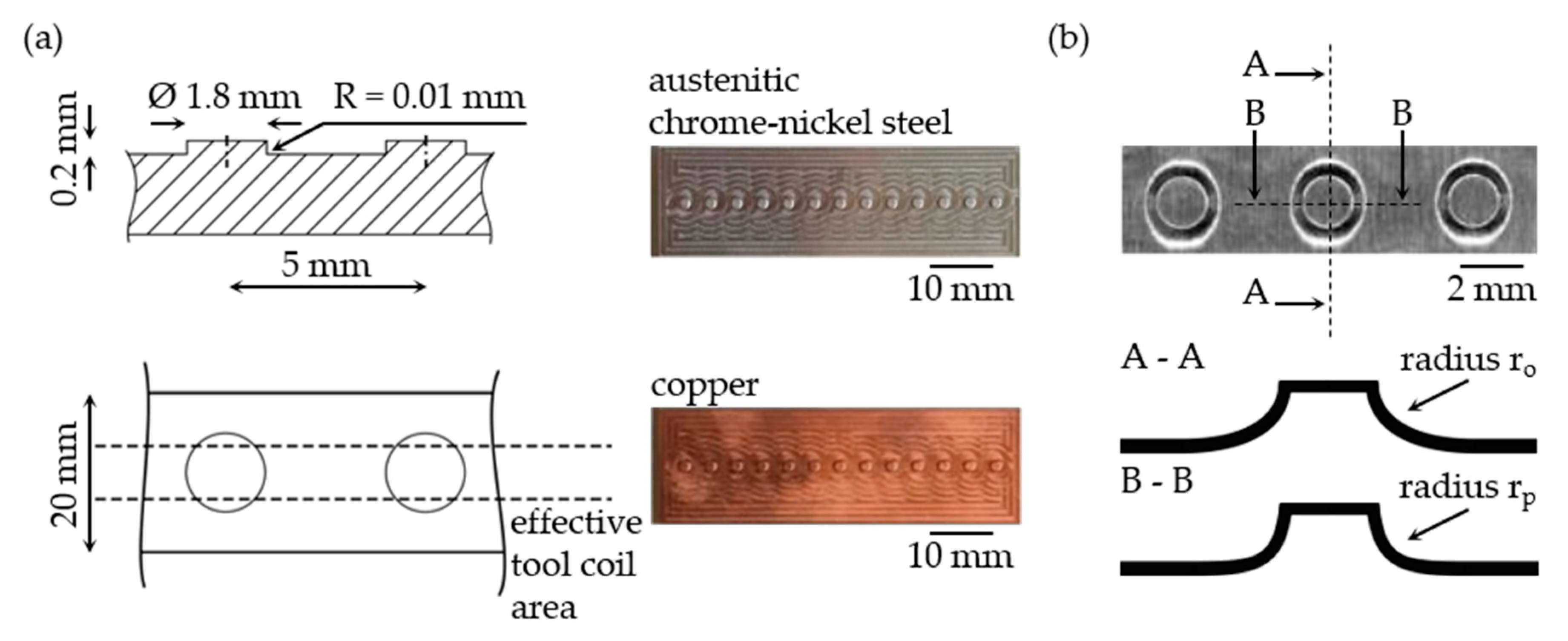
2.1. Die Material

The ranges of the simulated electromagnetic die properties were chosen that they include real material properties. The specific resistance value was varied from 1 × 10⁻⁸ Ω·m to 1 Ω·m, the relative permeability ranged from 0.9 to 300. A change in relative permeability μr and specific conductivity ρ due to a change in temperature is not considered in the simulation.
During experiments, the variation of the electromagnetic properties was done by different die materials. The selection included common tool steels (90MnCrV8) with high specific resistance and high relative permeability. In the simulation part, the ferromagnetic properties of the tool steel were neglected, and a linear behavior was applied. Further, an austenitic chrome-nickel steel (X5CrNi18-10) with high specific resistance and a relative permeability of 1 was used. In contrast to the high specific resistance of ferrous based materials, copper and aluminium with a low specific resistance were also applied as die material. The applied specific resistance and the relative permeability for the used die materials and for the used aluminium sheet metal for simulation is shown in Table 1 [24].

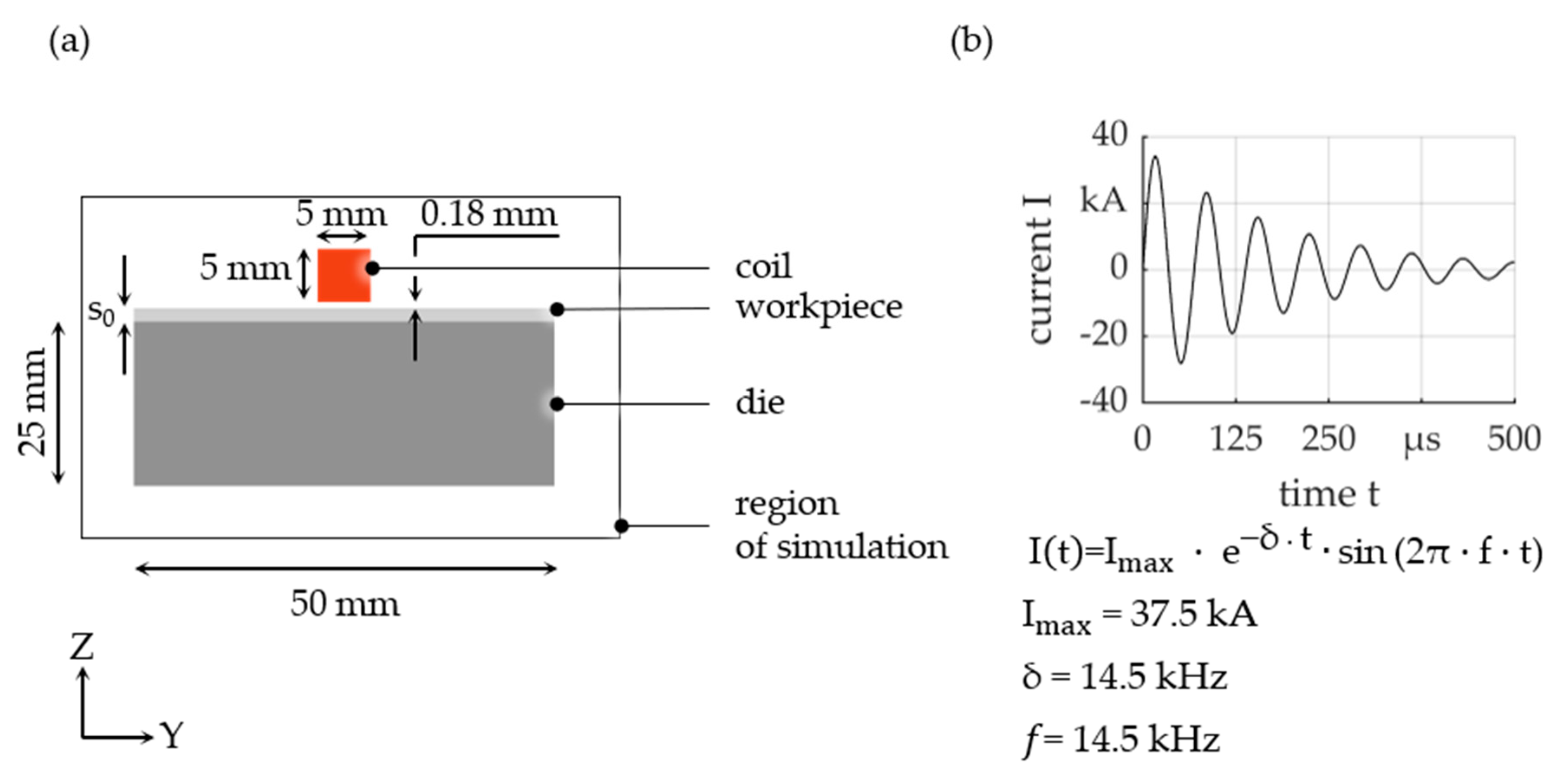
2.2. Simulation Model

A two-dimensional planar electromagnetic simulation model within the software environment ANSYS Maxwell 2D 19.1.0 was used in this work. The magnetic transient model consisted of four elements; coil, workpiece, die and surrounding air, see Figure 1a. The maximum mesh element length for the sheet metal was set to 0.02 mm. For all other parts of the model the maximum mesh element length was set to 0.5 mm. A triangular mesh with an adaptive mesh algorithm was applied. As tool coil, a single straight conductor was used to receive a plane symmetric magnetic field, which can be described in the planar area. Mutual interactions between the magnetic field and both the changing geometry during forming and the die cavity were avoided by applying a flat die. Thus, a coupled mechanical model of the electromagnetic forming was not necessary. Due to the use of a single straight conductor with low inductance, the discharge is largely determined by the electrical properties of the capacitor system. Changes to the coil-workpiece-die system therefore play a subordinate role. Following a constant discharge was used in simulation. During all simulations, the input current in Figure 1b was used. The current based on a charging energy EC = 1200 J discharge was modelled as a damped sine function with a frequency of f = 14.5 kHz, a maximum current amplitude of Imax = 37 kA and a damping factor of 5600. All simulations were evaluated in 1 μs time steps. According to Equation (1), the corresponding skin depth in aluminium (Al99.5) was 678 μm. During all simulations, sheet metal with a thickness of s0 = 200 μm was used. As a result, the initial electromagnetic field was not shielded completely by the sheet metal and hence, a current was generated in the die depending on the die material. To specify the impact, the impulse J of the sheet metal was calculated by integrating the body force FLN in -Z direction over the whole volume of the workpiece, see Equation (3) and over four current periods T of the oscillating circuit described by the damped sine oscillation:
J = 0 4 · T F L N , x d t

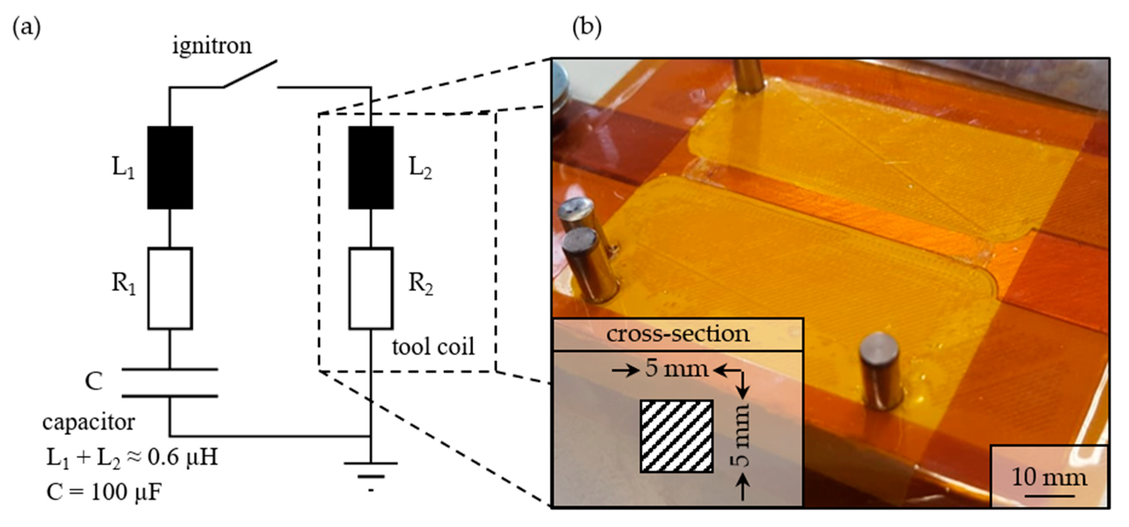
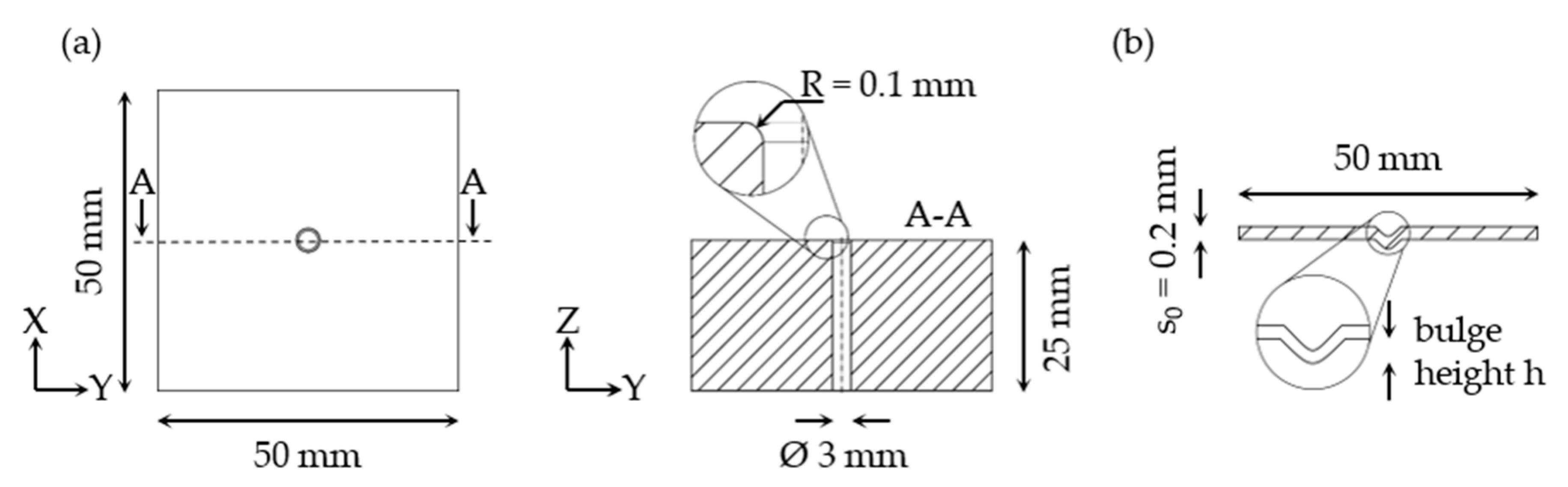
2.3. Experimental Setup

During the experiments, a capacitor bank (capacity of C = 100 μF) with a maximum charging energy of EC = 1800 J at maximum charging voltage of U0 = 6 kV was used, see Figure 2a. Forming experiments were carried out with charge energy of 1200 J. Switching was done by a single ignitron (NL508/NL508A, National Electronics, LaFox, IL, USA). The inductance of the circuit including the tool coil was approximately L = 0.6 μH. As tool coil, a single straight conductor with a rectangular cross-section of 5 × 5 mm2 was applied (Figure 2b). The tool coil was made of copper (E-Cu57) by milling. It was embedded in a polylactide carrier structure and insulated from the workpiece with 195 μm thick polyimide foil.
Al99.5 sheets with a thickness of s0 = 200 μm dimensioned 50 × 50 mm2 were used during the experiments. In combination with the single straight conductor coil and capacitor bank used in the tests, the skin depth in the aluminium sheet metal was 678 μm. Therefore, the die is in the range of the electromagnetic field during the experiments. For validation of the simulation results, four dies for free bulging were used, see Figure 3a.
During the experiments, five workpieces were formed with each die. The convex side of the formed sheet metal geometry was measured by a laser confocal microscope (VXK-210, Keyence, Itasca, IL, USA). With these measurements, the die specific bulge height h was determined. The bulge height was defined as the maximum distance of the convex formed sheet geometry and the undeformed flange geometry (see Figure 3b).
Furthermore, embossing experiments were carried out on raised circular structures, regarding the transfer of the results to replication processes, (see Figure 4a). These experiments were carried out with Al99.5 sheets with a thickness of 50 μm and 800 J charge energy. Austenitic chrome-nickel steel (X5CrNi18-10) and copper (E-Cu57) dies were used. The corner radius r achieved along and perpendicular to the effective tool coil area was determined as a measure for the embossing result (see Figure 4b). The measurements were carried out with a laser confocal microscope (Keyence VXK-210).

3. Results

3.1. Simulation Results

In a first step, the simulated impulses J on the workpiece were plotted against the resulting skin depth δ of the die material (see Equation (1)). The impulse J could not be correlated to the skin depth δ and the maximum values can be achieved with different combinations of specific resistance ρ and relative permeability μr values (see Figure 5). In contrast to influence of sheet metal thickness in electromagnetic forming, the electromagnetic die properties must influence the impulse on the sheet metal independently.
The influence of relative permeability μr and specific resistance ρ on the impulse J of the workpiece is shown in Figure 6. The impulse J rises significantly with the specific resistance ρ until a maximum value is reached at about 1 × 10⁻⁵ Ω·m. Further increasing specific resistance ρ does not affect the impulse J. With an increase of the relative permeability μr, the impulse J also increases. Thus, the die material must be chosen carefully for efficient electromagnetic forming of thin sheets with the demand of minimum specific resistance ρ and high relative permeability μr.
The process effect of the electromagnetic force depends on the current density j, the magnetic flux density B and electric field strength E in the workpiece (see Equation (2)). Based on this, the die material must have an influence on the current density j, magnetic flux density B, magnetic field strength H or the electric field strength E in the workpiece. Figure 7 shows the dependence of the maximum current density jmax in the sheet volume as a function of the die material properties. An increase in the current density j is caused by high specific resistance ρ and relative permeability μr values. Thus, the increased pulse could be explained by an increased current density j.
To analyse the effect of the electromagnetic field penetrating the die, the electric charge q of the die is calculated, by the integral current density j in the die y-z-surface over time t. This value enables the investigation of the energy which is transferred in the die. The electric charge q is reduced by an increased relative permeability μr and specific resistance ρ (see Figure 8), so a current flow in the die is suppressed by the material properties.
According to a current flow in the die, an electromagnetic field is induced from the die. This field causes a force to act against the forming direction, which reduce or can even result in a negative impulse JN. Corresponding to the current flow in the die, it is induced for low specific resistances ρ and low relative permeability μr (see Figure 9). So, the impulse J during electromagnetic forming is decreased though the acting of the inducted die current density j.
In addition to the influence of the die material on the current density j in the workpiece, the field changes in strength and shape by the different material properties. Figure 10 and Figure 11 shows this change in the field regarding the material properties, each highest and lowest specific resistance ρ and relative permeability μr. For dies with high relative permeability μr within the die volume, a low field strength H is present. However, this is followed by a field concentration within the sheet volume which leads to a higher impulse J. A decrease of the field strength H is observed by the increase of the specific resistance ρ. However, the field is more concentrated in the die for a low specific resistance ρ, thus the impulse J is lower for the workpiece due to the higher effect in opposite direction.
For a further comparison of the influence of the die material properties on the magnetic field, a normal distribution of the field is assumed. The average magnetic field strength Ha is calculated as the average in the workpiece volume at the time step of the maximum tool coil current. In respect of the electromagnetic die properties the results are shown in Figure 12. The average field strength Ha in the workpiece can be increased with high relative permeability μr and high specific resistance ρ of the die material.
To show the influence of the die material properties on the distribution of the field strength H which penetrates the workpiece, the deviation of the distribution of the field strength Hd in the workpiece volume during maximum tool coil current is shown in Figure 13. Once more, a high relative permeability μr and a high specific resistance ρ increase the spread of the field strength H in the workpiece. Thus, the spread or the effective range of the electromagnetic field of the tool coil is changed by the die material properties.

3.2. Experimental Results

Based on the electromagnetic simulation, an initial qualitative confirmation of the results can be carried out by comparison with experiments. Due to the dependence of the impulse J on the current density j (see Equation (2)), which in turn influences the plastic material behavior, a clear validation by the forming result is not possible with the actual model. The correlation in Figure 14 of the impulse to the forming result, which represented by the bulge height h, shows a linear dependence with good agreement. The results of the simulation model are confirmed under the boundary condition that more impulse causes a greater forming result. In contrast to this are the effects from the change of the plastic material behavior, which can be traced back to the die material. First, the current density in the workpiece is changed, which results in an influence on the plastic material properties by exceeding the limiting current density described in the literature (EPE) [21]. At the same time in dependence of the die material, current flow and forming lead to heating, which affect the material properties during forming. Likewise, it cannot be ruled out that different temporal and local force effects, which are not considered by the impulse, lead to a change in the strain rate and strain state, as well their material property dependencies. Regarding the differentiated consideration into influence of the relative permeability μr, the influence on the impulse can be confirmed by the comparison of the iron-based dies with different relative permeability μr and comparable specific resistance ρ. The impact of specific resistance ρ is shown by comparing the results of aluminium or copper-based dies with austenitic chrome-nickel steel-based dies, which have comparable relative permeability μr.
Regarding the embossing by electromagnetic forces, the performance of electromagnetic embossing can be increased by the influence of the die material. The influence of the die material is shown in Figure 15 by comparing the achieved inner corner radii r. Austenitic chrome-nickel steel-based dies achieve smaller radii r than copper-based tools, with lower specific resistance ρ for both directions considered. This makes embossing with steel-based dies more efficient in terms of die properties.

4. Conclusions

In the case that the die is within the effective range of the electromagnetic wave, an influence of electromagnetic properties of the die material on the forming process can be proven in simulation and experiments. The specific resistance ρ and relative permeability μr influence the transmitted impulse J during the forming process. Both a high specific resistance ρ and a high relative permeability μr of the die material cause a higher impulse. The following conclusions can be drawn:
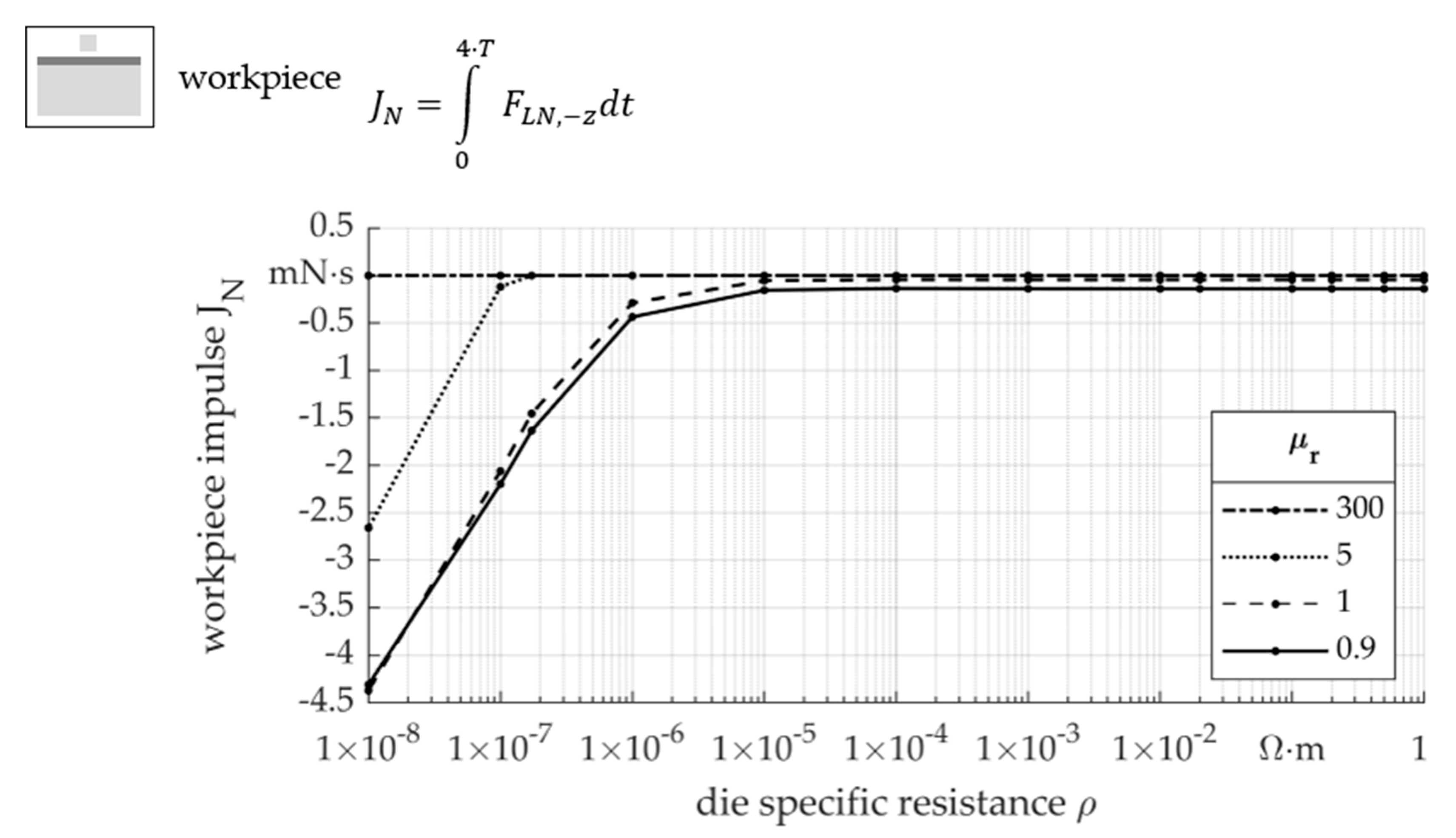
  • Below a specific resistance ρ of around 10−5 Ω·m, a decrease in the workpiece impulse during electromagnetic forming can be expected. To increase forming efficiency, the die material should have a higher specific resistance ρ.
  • The relative permeability influences the impulse up to a relative permeability μr of 5, whereby the influence decreases with higher relative permeability μr. A high relative permeability μr is positive regarding process efficiency.
  • The influence of the die material on the impulse J is due to the current density j in the workpiece. A high specific resistance ρ and relative permeability μr cause higher current densities j, which increases the impulse J on the workpiece.
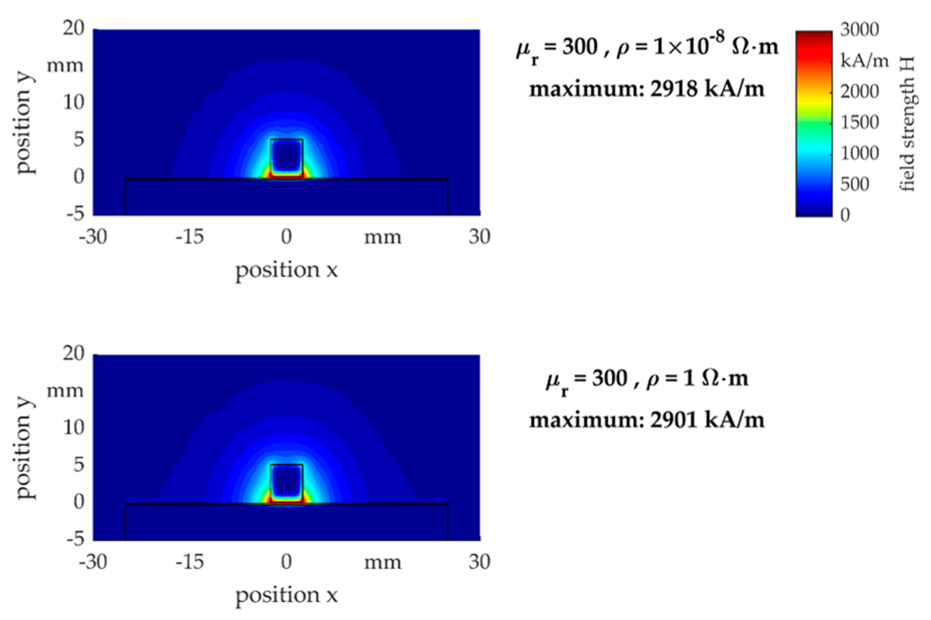
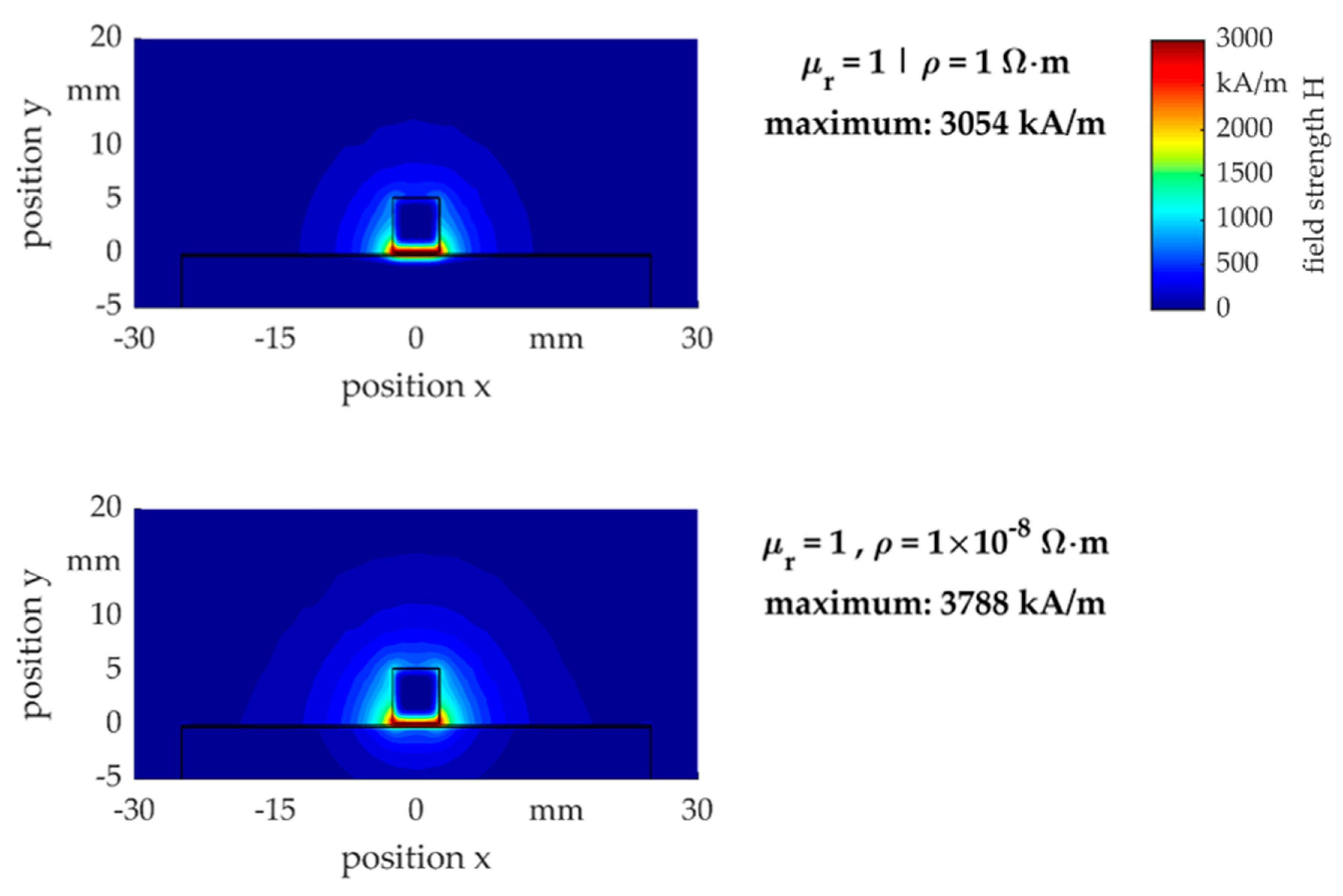
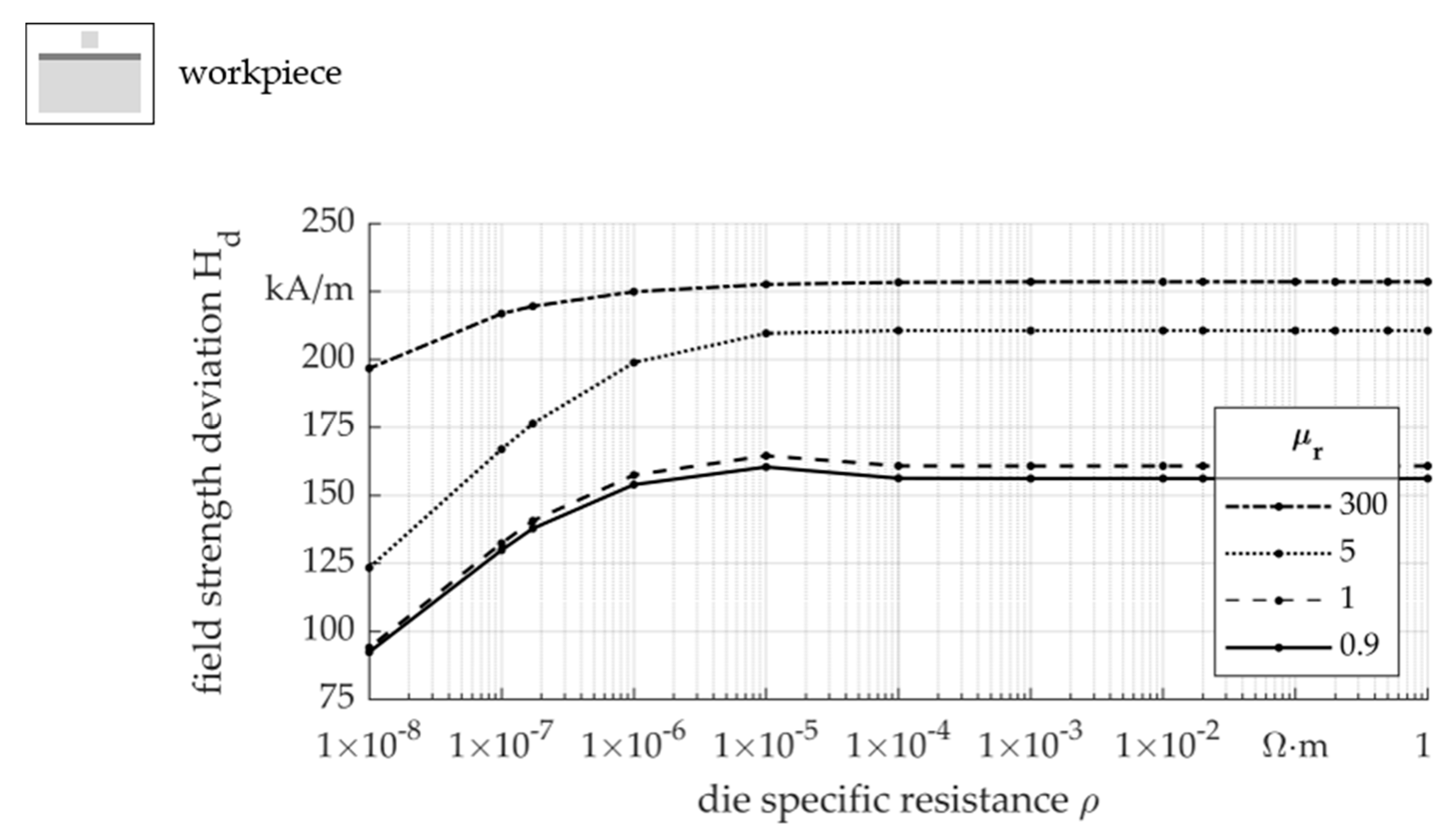
  • The properties of the die material influence the field, which can be seen in the change of the distribution and level of the field strength H. A high specific resistance ρ and relative permeability μr lead to a magnetic field concentration.
  • The results of the simulation confirmed by forming experiments using free forming of bulge structures.
  • The results of the simulation and free forming could be transferred to electromagnetic embossing and it could be shown that an improvement of the impression is possible due to the die material influence.
From the consideration of the influence of the electromagnetic properties of the die material it can be concluded that the die with material properties and geometry by local changes influences the process. Consequently, when designing the process for electromagnetic forming thin sheet metal, it is necessary to consider the repercussions of the die properties and the cavity. In combination with the dependency of thin sheet metal on the discharge frequency, the die, workpiece, tool coil and impulse forming system must be considered. In addition to this additional effort in the process design, the influence of the die material offers a possibility to improve the performance of the forming process by local adaptation via the die. With this aim, the influence of the die on the produced geometry and the conditions prevailing during the process must be determined. Thus, the impulse is changed during the forming process, but beyond that, influences regarding workpiece temperature and strain rate are expected. According to this thesis, influences on the plastic material behaviour of the workpiece following, so that the changed generated geometry cannot be entirely explained by different impulses.

Author Contributions

Conceptualization, B.B. and L.L.; methodology, B.B.; software, B.B.; validation, B.B. and L.L.; formal analysis, B.B.; investigation, B.B. and L.L.; resources, B.K.; data curation, B.B.; writing—original draft preparation, B.B., C.S., L.L. and M.H.; writing—review and editing, B.B., C.S., L.L., M.H. and B.K.; visualization, B.B.; supervision, B.K.; project administration, B.K.; funding acquisition, L.L., C.S., M.H. and B.K. All authors have read and agreed to the published version of the manuscript.

Funding

This research was funded by the Deutsche Forschungsgemeinschaft (German Research Foundation—DFG), grant number 395821503.

Data Availability Statement

The data presented in this study are available on request from the corresponding author.

Acknowledgments

The authors gratefully acknowledge the support by the German Research Foundation DFG for the project “Electromagnetic embossing of optical microstructures”.

Conflicts of Interest

The authors declare no conflict of interest.

References

  1. Kleiner, M.; Beerwald, C.; Homberg, W. Analysis of Process Parameters and Forming Mechanisms within the Electromagnetic Forming Process. CIRP Ann. 2005, 54, 225–228. [Google Scholar] [CrossRef]
  2. Psyk, V.; Kurka, P.; Kimme, S.; Werner, M.; Landgrebe, D.; Ebert, A.; Schwarzendahl, M. Structuring by electromagnetic forming and by forming with an elastomer punch as a tool for component optimisation regarding mechanical stiffness and acoustic performance. Manuf. Rev. 2015, 2, 23. [Google Scholar] [CrossRef] [Green Version]
  3. Kuhfuss, B.; Schenck, C.; Wilhelmi, P.; Langstädtler, L. Magnetic pulse cutting of micro metal foils. In Proceedings of the 8th International Conference of Micromanufacturing, ICOMM, Victoria, BC, Canada, 25–28 March 2013. [Google Scholar]
  4. Jimbert, P.; Pérez, I.; Eguia, I.; Daehn, G. Straight Hemming of Aluminum Sheet Panels Using the Electromagnetic Forming Technology: First Approach. Key Eng. Mater. 2007, 344, 365–372. [Google Scholar] [CrossRef]
  5. Kamal, M.; Shang, J.; Cheng, V.; Hatkevich, S.; Daehn, G.S. Agile manufacturing of a micro-embossed case by a two-step electromagnetic forming process. J. Mater. Process. Technol. 2007, 190, 41–50. [Google Scholar] [CrossRef]
  6. Taebi, F.; Demir, O.K.; Stiemer, M.; Psyk, V.; Kwiatkowski, L.; Brosius, A.; Blum, H.; Tekkaya, A.E. Dynamic forming limits and numerical optimization of combined quasi-static and impulse metal forming. Comput. Mater. Sci. 2012, 54, 293–302. [Google Scholar] [CrossRef]
  7. Langstädtler, L.; Schönemann, L.; Schenck, C.; Kuhfuss, B. Electromagnetic embossing of optical microstructures. J. Micro Nano Manuf. 2016, 4, 1–4. [Google Scholar] [CrossRef]
  8. Li, H.W.; Yao, X.; Yan, S.; He, J.; Zhan, M.; Huang, L. Analysis of forming defects in electromagnetic incremental forming of a large-size thin-walled ellipsoid surface part of aluminum alloy. J. Mater. Process. Technol. 2018, 255, 703–715. [Google Scholar] [CrossRef]
  9. Iriondo, E.; Gutiérrez, M.A.; González, B.; Alcaraz, J.L.; Daehn, G.S. Electromagnetic impulse calibration of high strength sheet metal structures. J. Mater. Process. Technol. 2011, 211, 909–915. [Google Scholar] [CrossRef]
  10. Harvey, G.W.; Brower, D.F. General Dynamics Corp. Metal Forming Device and Method. U.S. Patent 2,976,907, 28 March 1961. [Google Scholar]
  11. Psyk, V.; Risch, D.; Kinsey, B.L.; Tekkaya, A.E.; Kleiner, M. Electromagnetic forming—A review. J. Mater. Process. Technol. 2011, 211, 787–829. [Google Scholar] [CrossRef]
  12. Yu, H.; Li, C. Effects of current frequency on electromagnetic tube compression. J. Mater. Process. Technol. 2009, 209, 1053–1059. [Google Scholar] [CrossRef]
  13. Risch, D.; Beerwald, C.; Brosius, A.; Kleiner, M. On the Significance of the Die Design for Electromagnetic Sheet Metal Forming. In Proceedings of the International Conference on High Speed Forming, ICHSF, Dortmund, Germany, 31 March–1 April 2004; pp. 191–200. [Google Scholar] [CrossRef]
  14. Thibaudeau, E.; Kinsey, B.L. Analytical design and experimental validation of uniform pressure actuator for electromagnetic forming and welding. J. Mater. Process. Technol. 2015, 215, 251–263. [Google Scholar] [CrossRef]
  15. Paese, E.; Geier, M.; Homrich, R.P.; Rossi, R. A coupled electric–magnetic numerical procedure for determining the electromagnetic force from the interaction of thin metal sheets and spiral coils in the electromagnetic forming process. Appl. Math. Model. 2015, 39, 309–321. [Google Scholar] [CrossRef]
  16. Langstädtler, L.; Schenck, C.; Kuhfuss, B. Effective electromagnetic forces in thin sheet metal specimen. MATEC Web Conf. 2015, 21, 11002. [Google Scholar] [CrossRef] [Green Version]
  17. Cao, Q.; Li, Z.; Lai, Z.; Li, Z.; Han, X.; Li, L. Analysis of the effect of an electrically conductive die on electromagnetic sheet metal forming process using the finite element-circuit coupled method. Int. J. Adv. Manuf. Technol. 2019, 101, 549–563. [Google Scholar] [CrossRef]
  18. Kravchenko, V.Y. Effect of directed electron beam on moving dislocations. Sov. Phys. JETP 1967, 24, 1135–1142. [Google Scholar]
  19. Wang, X.; Xu, J.; Wang, C.; Sánchez Egea, A.J.; Li, J.; Liu, C.; Wang, Z.; Zhang, T.; Guo, B.; Cao, J. Bio-Inspired Functional Surface Fabricated by Electrically Assisted Micro-Embossing of AZ31 Magnesium Alloy. Materials 2020, 13, 412. [Google Scholar] [CrossRef] [PubMed] [Green Version]
  20. Unger, J.; Stiemer, M.; Walden, L.; Bach, F.; Blum, H.; Svendsen, B. On the effect of current pulses on the material behavior during electromagnetic metal forming. In Proceedings of the 2nd International Conference on High Speed Forming, Dortmund, Germany, 20–21 March 2006; pp. 23–32. [Google Scholar]
  21. Gallo, F.; Satapathy, S.; Ravi-Chandar, K. Plastic deformation in electrical conductors subjected to short-duration current pulses. Mech. Mater. 2012, 55, 146–162. [Google Scholar] [CrossRef]
  22. Sánchez Egea, A.J.; Peiró, J.J.; Signorelli, J.W.; González Rojas, H.A.; Celentano, D.J. On the microstructure effects when using electropulsing versus furnace treatments while drawing inox 308L. J. Mater. Res. Technol. 2019, 8, 2269–2279. [Google Scholar] [CrossRef]
  23. Wang, X.; Sánchez Egea, A.J.; Xu, J.; Meng, X.; Wang, Z.; Shan, D.; Guo, B.; Cao, J. Current-Induced Ductility Enhancement of a Magnesium Alloy AZ31 in Uniaxial Micro-Tension Below 373 K. Materials 2018, 12, 111. [Google Scholar] [CrossRef] [PubMed] [Green Version]
  24. ANSYS. Material Database; ANSYS: Canonsburg, PA, USA, 2019. [Google Scholar]
  25. Langstädtler, L. Elektromagnetisches und Elektrohydraulisches Umformen in der Mikroproduktion. Ph.D. Thesis, Universität Bremen, Bremen, Germany, 2020. [Google Scholar] [CrossRef]
Figure 1. Simulation model; (a) schematic; (b) input current (tool coil).
Jmmp 05 00018 g001
Figure 2. Experimental setup; (a) equivalent circuit diagram; (b) tool coil.
Jmmp 05 00018 g002
Figure 3. Forming experiment; (a) free forming die geometry; (b) resulting workpiece geometry.
Jmmp 05 00018 g003
Figure 4. Embossing experiment; (a) die geometry; (b) resulting workpiece geometries.
Jmmp 05 00018 g004
Figure 5. Simulated impulse as a function of the resulting skin depth for the parameter combination of specific resistance ρ and relative permeability μr values.
Jmmp 05 00018 g005
Figure 6. Simulated impulse J on thin aluminium sheets for different electromagnetic properties of the die material.
Jmmp 05 00018 g006
Figure 7. Maximum current density jmax in the workpiece volume in respect of the specific resistance ρ of the die material.
Jmmp 05 00018 g007
Figure 8. Integral of the current density j in the die volume over time in respect of the specific resistance ρ of the die material.
Jmmp 05 00018 g008
Figure 9. Integral of the negative force components over time in respect of the specific resistance ρ of the die material.
Jmmp 05 00018 g009
Figure 10. Distribution of the magnetic field with high relative permeability μr of the die during the maximum current density in the tool coil.
Jmmp 05 00018 g010
Figure 11. Distribution of the magnetic field with low relative permeability μr of the die during the maximum current density in the tool coil.
Jmmp 05 00018 g011
Figure 12. Average magnetic field strength Ha in the workpiece in respect of the specific resistance ρ of the die material.
Jmmp 05 00018 g012
Figure 13. Field strength deviation Hd (standard deviation of the magnetic field strength) in the workpiece in respect of the specific resistance of the die material.
Jmmp 05 00018 g013
Figure 14. Corresponding experimental bulge height h for the simulated impulse J for different die materials with linear correlation line for a 1250 J forming experiment.
Jmmp 05 00018 g014
Figure 15. Comparison of the inner corner radius in two directions and the embossing result of two embossing dies made of austenitic chrome-nickel steel and copper, cf. [25].
Jmmp 05 00018 g015
Table 1. Electromagnetic properties of the used die and workpiece materials from the ANSYS database.
MaterialSpecific Resistance
ρ [Ω·m]
Relative Permeability
μr [-]
dieaustenitic chrome-nickel steel
X5CrNi18-10/AISI 304
9.0909 × 10−71.000000
cold work tool steel
90MnCrV8/AISI O2
5 × 10⁻⁷~300
copper
E-Cu57/C11000/ETP
1.7241 × 10−80.999991
aluminium
AlCuMgPb/AA2007
2.6316 × 10−81.000021
workpiecealuminium
Al99.5/AA1050A
2.6316 × 10−81.000021
Publisher’s Note: MDPI stays neutral with regard to jurisdictional claims in published maps and institutional affiliations.

