Article

Experimental Study on Joining by Forming of HCT590X + Z and EN-AW 6014 Sheets Using Cold Extruded Pin Structures

Institute of Manufacturing Technology, Friedrich-Alexander-Universität Erlangen-Nürnberg, Egerlandstraße 13, 91058 Erlangen, Germany
*
Author to whom correspondence should be addressed.
J. Manuf. Mater. Process. 2021, 5(1), 25; https://0-doi-org.brum.beds.ac.uk/10.3390/jmmp5010025
Submission received: 1 March 2021 / Revised: 13 March 2021 / Accepted: 15 March 2021 / Published: 17 March 2021
(This article belongs to the Special Issue Metal Forming and Joining)

Abstract

:
Due to stricter emission targets in the mobility sector and the resulting trend towards lightweight construction in order to reduce weight and consequently emissions, multi-material systems that allow a material to be placed in the right quantity and in the right place are becoming increasingly important. One major challenge that is holding back the rapid and widespread use of multi-material systems is the lack of adequate joining processes that are suitable for joining dissimilar materials. Joining processes without auxiliary elements have the advantage of a reduced assembly effort and no additional added weight. Conventional joining processes without auxiliary elements, such as welding, clinching, or the use of adhesives, reach their limits due to different mechanical properties and chemical incompatibilities. A process with potential in the field of joining dissimilar materials is joining without an auxiliary element using pin structures. However, current pin manufacturing processes are mostly time-consuming or can only be integrated barely into existing industrial manufacturing processes due to their specific properties. For this reason, the present work investigates the production of single- and multi-pin structures from high-strength dual-phase steel HCT590X + Z (DP600, t0 = 1.5 mm) by cold extrusion directly out of the sheet metal. These structures are subsequently joined with an aluminium sheet (EN AW-6014-T4, t0 = 1.5 mm) by direct pin pressing. For a quantitative evaluation of the joint quality, tensile shear tests are carried out and the influence of different pin heights, pin number, and pin arrangements, as well as different joining strategies on the joint strength is experimentally evaluated. It is proven that a single pin structure with a diameter of 1.5 mm and an average height of 1.86 mm achieves a maximum tensile shear force of 1025 N. The results reveal that the formation of a form-fit during direct pin pressing is essential for the joint strength. By increasing the number of pins, a linear increase in force could be demonstrated, which is independent of the arrangement of the pin structures.

1. Introduction

Global sales and market share of electric vehicles have been rising steadily for years and are further boosted in particular by government stimulus packages and innovation bonuses designed to support the reduction of the carbon quota of car manufacturers’ vehicle fleets. In this way, emissions are continuously reduced, especially in the mobility sector. In addition, electric vehicles are a key technology in reducing particulate pollution in urban areas and are expected to help achieve the challenging emission targets. According to the International Energy Agency [1], as of June 2020, 17 countries have announced targets for 100% emission-free vehicles or a phase-out of vehicles with internal combustion engines by 2050. However, even with electric vehicles, the vehicle weight plays a central role in energy consumption. As electricity is still generated to a large extent by fossil fuels worldwide—in 2018 it was 57.1% for OECD countries and even 71.7% for non-OECD countries [2]—it must be a goal to reduce the vehicle weight and thus energy consumption. Therefore, lightweight structures and multi-material systems are of great interest to companies in the mobility sector. However, the joining process of dissimilar materials presents a key challenge of these multi-material systems and conventional joining methods, such as welding, gluing, screwing, or riveting, reach their limits due to different stiffness, chemical incompatibilities, and thermal expansion coefficients. Furthermore, auxiliary joining elements, such as those required for screwing or riveting, lead to an increased weight and assembly effort. Thus, there is a great need for versatile joining processes that can react quickly to changing process parameters and varying joining partners. A mechanical joining strategy that has proven to be promising for joining dissimilar materials, such as metal–metal- or metal–fiber-reinforced plastics, is joining without additional auxiliary element using pin structures. The difference in joining without auxiliary elements is that no additional elements, such as rivets and screws, are necessary to join components. This results in a weight advantage compared to joining with an auxiliary element.
Considerable research has already been done on joining continuous fiber-reinforced plastics (CFRP) to metal components by using pin structures located on the surface of the metal components. There are different methods to join the CFRP to the pin structures. Smith [3] used dry preformed glass fibers placed around the pin structures to make the metal-CFRP bond in her work. In the next step, polyester resin was vacuum infused into the glass fabric and consolidated to form the matrix of the CRRP. In contrast, Parkes et al. [4] used pre-impregnated material into which the pin structures were pressed using an ultrasonic probe. As a result, the matrix was heated and the viscosity was reduced in order to increase the mobility of the fibers and to minimize the risk of fiber damage during joining. The metal–CFRP joint was then co-bonded in the final step in an autoclave. In addition to the use of thermosetting plastics, thermoplastics can also be used as matrix materials. Thakkar et al. [5] used pre-consolidated glass fiber/polypropylene prepregs for their research. These were placed in an oven before joining to heat the matrix to melting temperature. As in [4], this reduces the viscosity of the matrix, which allows the fibers to rearrange in the matrix as soon as the pins are pressed into the CFRP in the subsequent step using a punch. After the joining process, the plastic cools down due to contact with the tool and reconsolidates. Plettke et al. [6] also used a thermoplastic matrix filled with glass fibers. The pin structures were produced using additive manufacturing (AM) and pressed through the pre-heated CFRP in the following step. Due to the greater pin height compared to the sheet thickness of the CFRP joining partner, the pins were additionally caulked in contrast to [5]. When investigating the strength of single lap shear pin connections made of titanium and CFRP with cylindrical pin structures in a 6 × 6 array, Parks et al. [7] found a 25% higher limit load and a factor of 6.5 higher ultimate load compared to samples without pin structures. Ucsnik et al. [8] were able to demonstrate up to 3000% higher energy absorption in the shear test through the use of pin structures, compared to samples without pins. Although there is a large number of publications on joining metal CFRP with pin structures, only a few publications are currently published that deal with joining dissimilar metals using pin structures.
However, pin structures also show great potential for joining metals. Kraus et al. [9] demonstrated the suitability of cold-formed pin structures for joining DC04 steel with the aluminium alloy AA6016-T4. Direct pin pressing (DPP) and caulking were investigated as alternative joining techniques. For direct pin pressing, the cylindrical pin structures produced with cold forming are pressed directly into the unperforated joining partner, creating an undercut by upsetting the pin within the joining partner. During caulking, the pin structure was inserted through a pre-punched joining partner and the head of the pin was upset to create a form and force-fit connection. The cylindrical pin structures used for joining had a diameter of 1.32 mm. In tensile shear tests, a maximum transmittable shear force of 702 N was achieved for the caulked and 363 N for the directly pressed single pin structures. In Kraus et al. [10], the effect of the number of pins in multi-pin structures on the tensile shear strength of the connection was numerically investigated. The simulations revealed a linear relationship between the pin count and strength. According to the work in [8], this can be attributed to the linear increase in the cross-sectional area for force transmission. Another process that can be mentioned in the context of joining dissimilar metals is resistance welding with an upset auxiliary element [11]. Here, a pre-punched aluminium sheet with embossed edges is joined with a steel sheet using a steel auxiliary element. For this purpose, the auxiliary element is first upset in the pre-punched aluminium sheet to achieve a form and force-fit connection, and then joined to the steel sheet using resistance welding.
One of the major challenges in joining with metallic pin structures is the pin production itself. There are numerous of processes for the fabrication of pin structures. According to Feistauer et al. [12], the available technologies can be divided into additive, subtractive, and molding manufacturing processes. Additive processes here include not only AM processes, but also processes that apply material to the surface of the components. These include cold metal transfer (CMT), arc percussive micro-welding (APMW), and various powder-based AM processes, such as powder bed fusion using a laser beam (PBF-LB) or laser metal deposition (LMD). Subtractive processes include classical machining and micro-machining, as well as the Surfi–Sculpt process, which was developed by Dance and Ewen [13] at The Welding Institute (TWI) in 2002. Metal injection molding (MIM) is also an industrially established process that can be used to produce pin structures. Based on the MIM process, Helmholtz-Zentrum Geesthacht [14] has developed and patented a process known as MIM structuring, which allows the production of surface-structured metallic components that have good geometric tolerance, surface quality, and geometric reproducibility of pin structures [12]. One advantage of the MIM process is the wide range of materials that can be used due to its widespread application in industry. Disadvantages, however, are the lower density of the components, whose porosity is in the range of 2 to 4%, as well as the complex process chain consisting of material production, injection molding of the green part, chemical and thermal debinding and finally sintering. Another disadvantage is the need to produce both the component and the pin structures in the same step, which limits the flexibility of the process in terms of application areas and, above all, component size [15].
The CMT process was introduced in 2004 by the Austrian company Fronius as a variant of gas metal arc welding. An innovative wire feed system in conjunction with a digital high-speed control system enables the material transport and heat input to be controlled in CMT [16]. The lower thermal input can have a positive effect on residual stresses as well as on the dimensional and shape accuracy of the welded components [17]. By actively controlling the welding wire in the process, pin structures with different pin head geometries can be realized on the surface of the components, which can be produced in a wide variety of different materials. The CMT process can be used to create spherical, cylindrical, and spiky pin structure geometries [18]. However, as it is a fusion welding technology, hydrogen embrittlement, solidification cracks, and the evaporation of alloying elements can occur, which is why inert gases are required to reduce these phenomena [12]. However, the production time of the pin structures has limited suitability for industrial application with a duration of almost 3 s for pin structures with a diameter of 1.2 mm and a height of 1.6 mm [19]. In addition to CMT, there is APMW, which can also attach pins to the surface of components by fusing them together. In this process, an arc generated by a discharge from a capacitor across a controlled gap between the pin and the component surface melts a small volume of the pin structure, which is pressed directly onto the component to create the joint. The welding cycle is very fast at <5 ms and the APMW makes it possible to join different materials [20].
Powder-based AM processes are another way of producing pin structures that can be used to join dissimilar materials [6]. In PBF-LB, powder is applied in layers in the process chamber and melted locally by a laser. This process is repeated iteratively until the desired component has been additively built. One advantage that AM offers over conventional processes is the geometric design freedom that allows almost any geometry to be realized. This means that pin structures can be adapted to the desired application. In contrast to this is the long process time, which makes industrial application difficult, as both the preparation of the build job and the production itself take a considerable amount of time. In addition, PBF-LB is limited by the build chambers of the machines, which restricts the component sizes. In order to reduce the limitations of the process in terms of speed, however, research is being conducted into the production of hybrid components [21], in which functional elements are built upon the surface of sheet materials using PBF-LB, reducing the processing time by saving on the production of the workpieces. LMD also uses metal powders to additively build up components layer by layer. However, here no layer of powder is applied to a platform, but instead is focused by nozzles in a laser beam and subsequently melted. Similar to PBF-LB, LMD also offers a high degree of geometric design freedom, but also has similar disadvantages in terms of production speed as far as industrial use is concerned. Graham et al. [22] describe a production time of 10 s for the manufacture of pins with a diameter of 1 mm and a height of 3 mm.
Machining, or micro-machining, is one of the most common manufacturing processes and is based on subtractively removing unwanted material from the component using tools. Micromachining includes different processes such as turning, milling, drilling, or grinding, which are used to create very small features and structures [23]. Di Giandomenico [24] used micromilling to structure the surface of titanium components to create pin geometries such as a shark tooth and a spike pin and subsequently join them with fiber-reinforced plastics with a thermoset matrix. The advantage of machining processes such as milling is the possibility to create different geometries. In addition, these processes are widely used in industrial environments. The Surfi–Sculpt process has been classified as a subtractive process, but this is not entirely accurate, as the process uses an energy beam to locally melt and displace material on the metal surface. This redistribution of material creates protrusions and intrusions on the surface of the components. These can be designed to have specific shapes and dimensions [25]. There are two variants of the process, which differ in their beam source. One uses an in-vacuum electron beam and the other a laser beam. An advantage of the Sufi–Sculpt process is the speed, as several hundred features can be produced on a 25 mm × 25 mm grid in about 10 s. However, depending on the energy source, it is also subject to some disadvantages. Due to the process, it is necessary to create a vacuum in the process chamber when processing with an electron beam, which limits the dimensions of the components to the chamber size. For this reason, a process variant with a laser as the energy source was developed to circumvent the limitations.
As described above, most pin manufacturing processes aim to produce pin structures on the surface of metallic components. This has advantages, for example, in the case of AM, that there are virtually no limitations with regard to the geometric design of the pin structures. In this way, the geometry can be adapted specifically to the application. However, these methods are usually difficult to integrate into existing manufacturing processes and often time-consuming. For a wide-ranging adaptation of the joining with pin structures, it is therefore essential that short cycle times can be realized, that the process can be integrated into existing production processes and that it can be adapted flexibly and quickly to changing process conditions. Cold forming of pin structures offers significant advantages compared to the described processes, as single- and multi-pin structures can be produced comparatively fast in just one stroke. In addition, the forming process offers the advantage of strain hardening, which has a positive effect on the strength of the pins and thus on the joint strength. The process also provides an excellent surface quality, which can have a positive effect on fiber rearrangement when pressed into fiber-reinforced plastics.

2. Materials and Methods

2.1. Materials

The sheet materials used in this work are a dual phase steel HCT590X + Z (DP600) and an aluminium alloy of the 6000 series EN AW-6014-T4. DP 600 steel is frequently used in automotive construction for crash-relevant components, like cross-members, and is used for structural components as well as for body parts. The DP600 steel sheet is cold-rolled and additionally galvanized. The EN AW-6014 aluminium sheet used is a precipitation-hardening aluminium-magnesium-silicon alloy and is in the naturally aged T4 temper. It was cold rolled to the desired sheet thickness as well and is typically used for hood outers, door outers, and fenders, but is also utilized in structural applications in automobiles. Due to the large number of joints required in the production of car bodies in the automotive industry, these materials were used to investigate the joining of dissimilar metals using pin structures. The chemical composition of the materials is listed in Table 1.
For the tensile shear test according to the standard DIN EN ISO 12,996 [26], the used specimens have a size of 108.5 × 40 mm2. Both sheets had a thickness of t0 = 1.5 mm. The material properties of the materials are listed in Table 2 and were determined using the uniaxial tensile test according to DIN EN ISO 6892-1 [27], in order to compare the materials with each other and to give an overview of the mechanical properties.

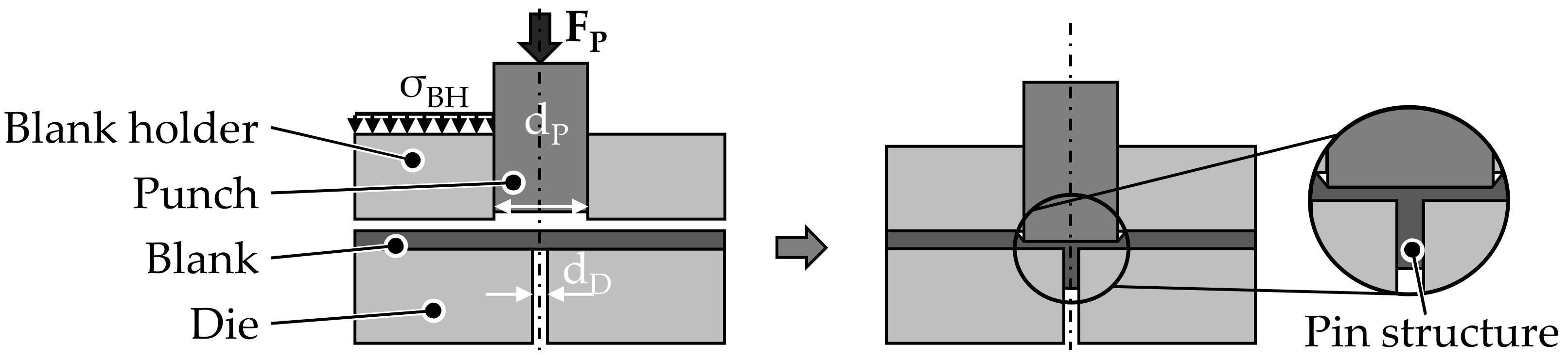
2.2. Cold-Forming of Pin Structures

The pin structures were manufactured by cold extrusion from the DP600 sheet. For this, a multi-acting tool, in which the blank holder and the punch can be moved independently of each other, is used. To prevent the steel sheet from bulging and to reduce the material flow radially outwards into the sheet metal plane, a constant blank holder pressure of 250 MPa is initially applied. After the blank holder pressure σBH has been applied, the pin structure is formed by moving the punch with a diameter dP of 3 mm axially at a constant speed vp of 5 mm/min. An illustration of the extrusion process is shown in Figure 1. The material is displaced both axially into the die with a diameter dD of 1.5 mm and laterally outwards into the sheet plane and the cavity. The pin height can thus be adjusted by the axial punch penetration depth, where a higher pin is realized by greater penetration of the punch into the sheet metal. To regulate the penetration depth of the punch, height-adjustable mechanical stops are used on which the punch moves as soon as the desired depth has been reached. Both the force of the punch and the blank holder as well as the axial displacement are recorded during the forming process. Dionol ST extrusion oil was used for lubrication. The relevant constant and varied process parameters which were used to manufacture and join the pin structures are summarized in Table 3. The joining process is described in more detail in Section 2.3.
Within the scope of this work, single pins with different heights are extruded from the sheet metal plane, joined in the next step using different joining strategies (without die and with a die with a diameter dDPP of 3 mm and 4 mm) and examined with regard to their tensile shear strength and compared with each other. In order to allow a better distinction of the different specimen, they are referred to by their label from the Table 3. In addition, multi-pin structures in two arrangements (longitudinal and transverse to the axes of symmetry) are also analyzed. Thus, the effect of the arrangement and the number of pin structures on the tensile shear strength can be examined separately. The different pin arrangements are shown in Figure 2. The multi-pin structures are formed sequentially, aiming for the same punch penetration depth previously used for the 1.45 mm single pins to be able to adequately compare the results. Due to the smaller edge distance of the outer pin in the longitudinal arrangement, more material flows into the sheet plane and less axially into the die due to the lower flow resistance. As a result, the punch penetration depth had to be readjusted and the punch had to penetrate deeper into the sheet to achieve the 1.55 mm pin height for both pins. With the transverse pin structure, the same punch penetration depth was realized for both pins, as there was a symmetrical material distribution here.

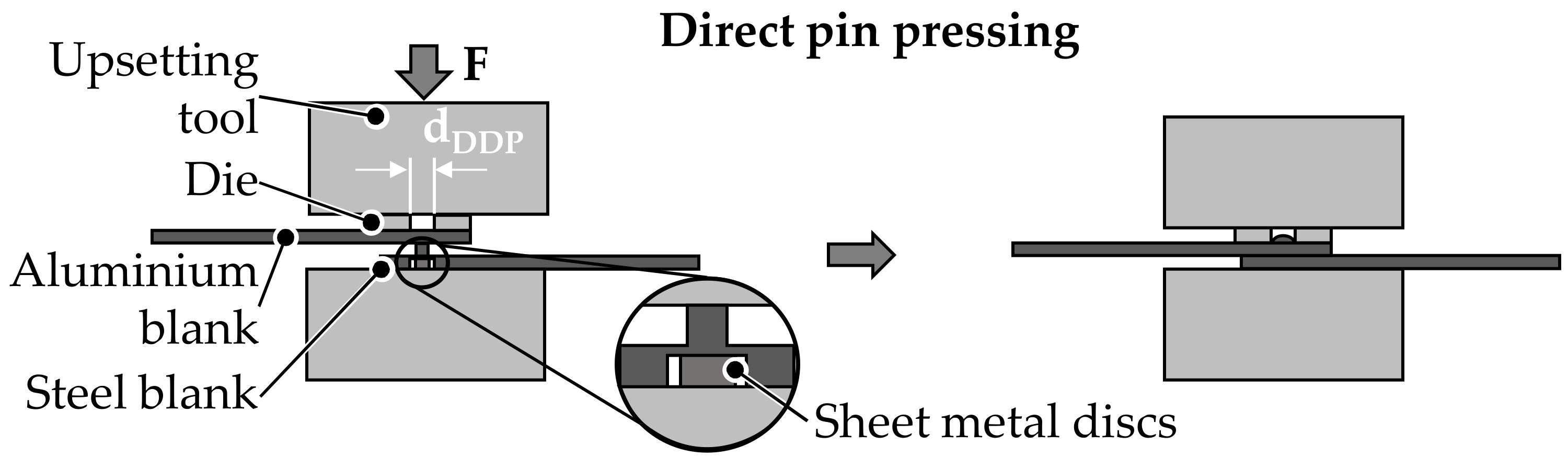
2.3. Joining by Forming—Direct Pin Pressing

In order to be able to characterize the direct pin pressing process, the test specimen made of DP600 containing the cold-formed pin structure is joined with the EN AW-6014-T4 sheet metal. For this purpose, the pin structure is pressed directly into the unperforated aluminium sheet using a Walter + Bai 300 universal testing machine and a conventional upsetting tool. The upsetting tool moves axially at a constant speed of 5 mm/min onto the overlapping sheets and presses the pin structure into the aluminium sheet until a force threshold of 25 kN is reached, which was sufficient to join the sheets and to upset the pin structures. In the process, the pin is upset by the tool in order to create an undercut and thus a force-fit and form-fit connection [28]. In the case of direct pin pressing of the single pins, two different joining strategies are examined in more detail. The joining is illustrated in Figure 3. A distinction is made between direct pressing without and with a round die. The diameter dDDP of the die was varied between 3 and 4 mm. The aim was to investigate whether the material flow and thus the formation of an undercut can be promoted due to the usage of a die during joining. Differences in the joint strength and the formation of the joint were investigated and compared depending on the investigated joining strategies. In order to prevent the sheet metal from fracturing or bending back into the punch cavity underneath the pin structure, fine sheet metal discs were placed in the punch impression to provide axial support for the pins during joining. When pressing the multi pin structures directly into the aluminium joining partners, no dies were used, as the effects of the joining strategies are investigated on the basis of the single pins in order to investigate the effect of the arrangement and number of the pin structures on the joint strength.

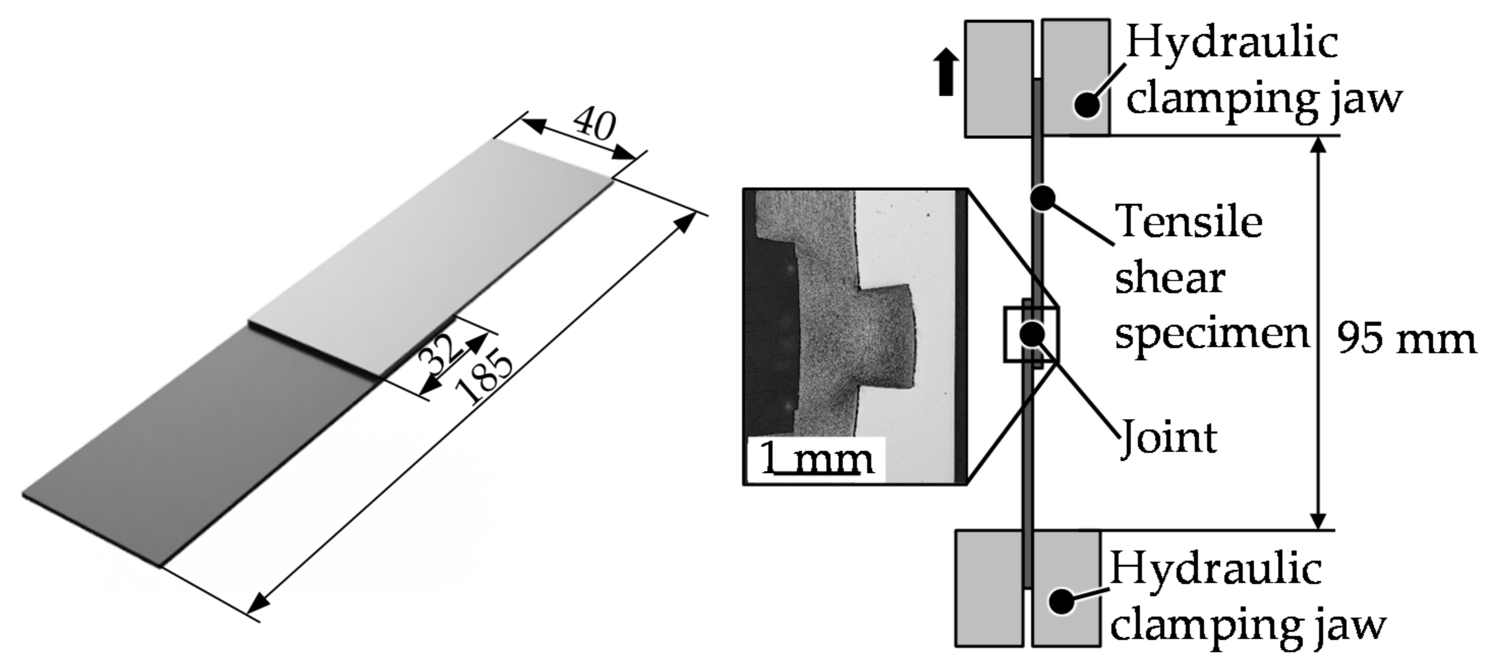
2.4. Mechanical Testing—Tensile Shear Test

The test specimens joined in this work are tested for their joint strength on a Zwick-10 universal testing machine using the tensile shear test in accordance with DIN EN ISO 12,996 [26]. The test specimens are fixed between two mechanical clamping jaws and secured against slipping with a constant clamping force. A free clamping length of 95 mm according of the DIN EN ISO 12,996 [26] is ensured. The tensile shear specimen and the test setup are illustrated in Figure 4. For the test itself, the upper jaw moves upwards with a constant speed of 10 mm/min until the connection fails completely. For the analysis, both the force of the load cell and the axial displacement was recorded.

3. Results and Discussion

In the following, the results of the cold forming of the pin structures, then the mechanical joining of the dissimilar materials, and finally the mechanical testing of the joints in the tensile shear test are analyzed. In addition, correlations between the investigated parameters are discussed. In particular, the influence of the pin height, pin count, and pin arrangement on the tensile shear strength is evaluated.

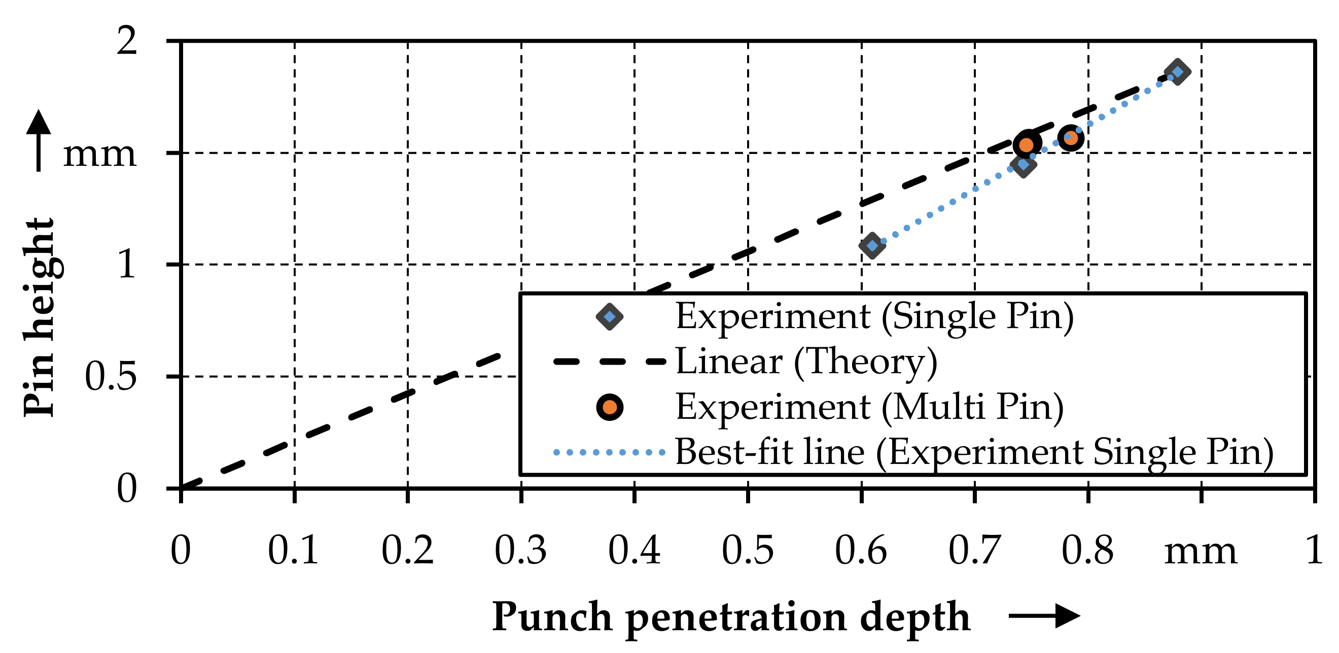
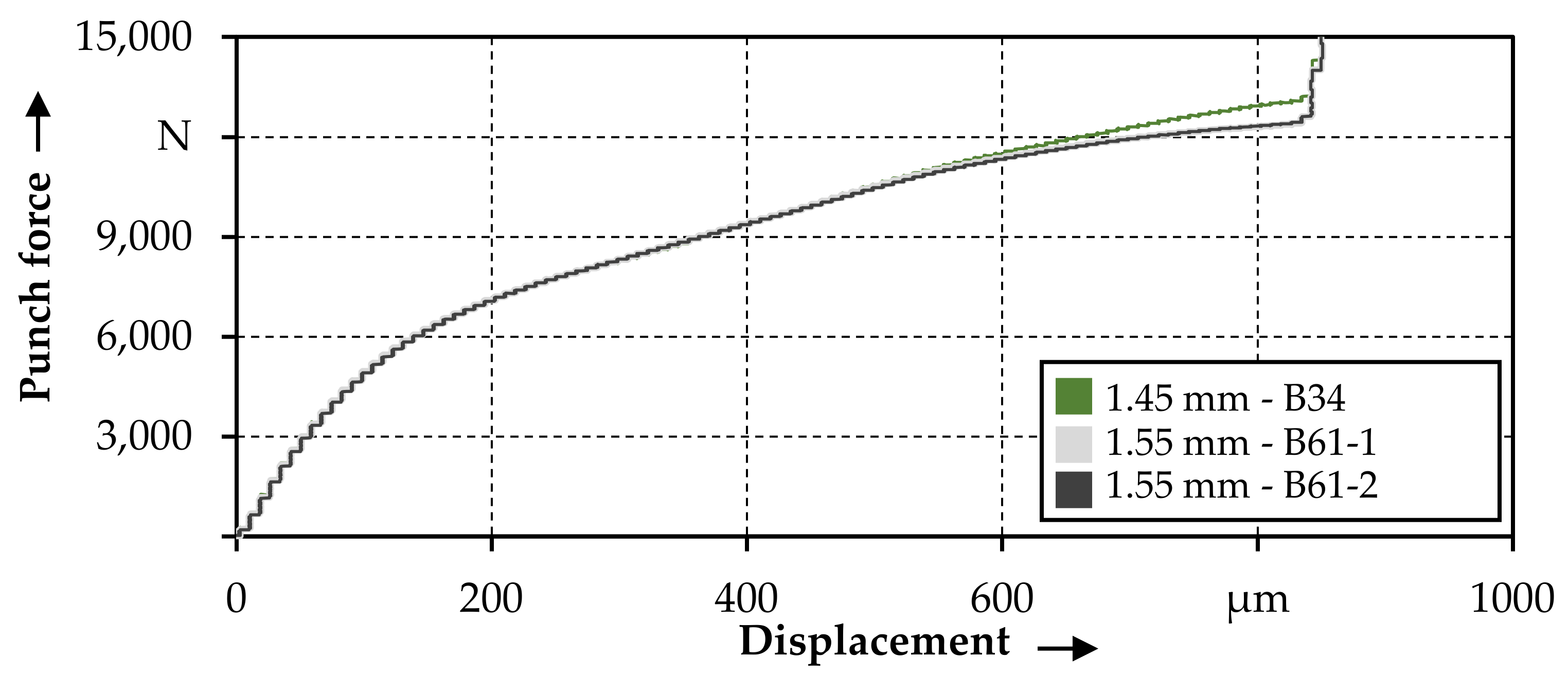
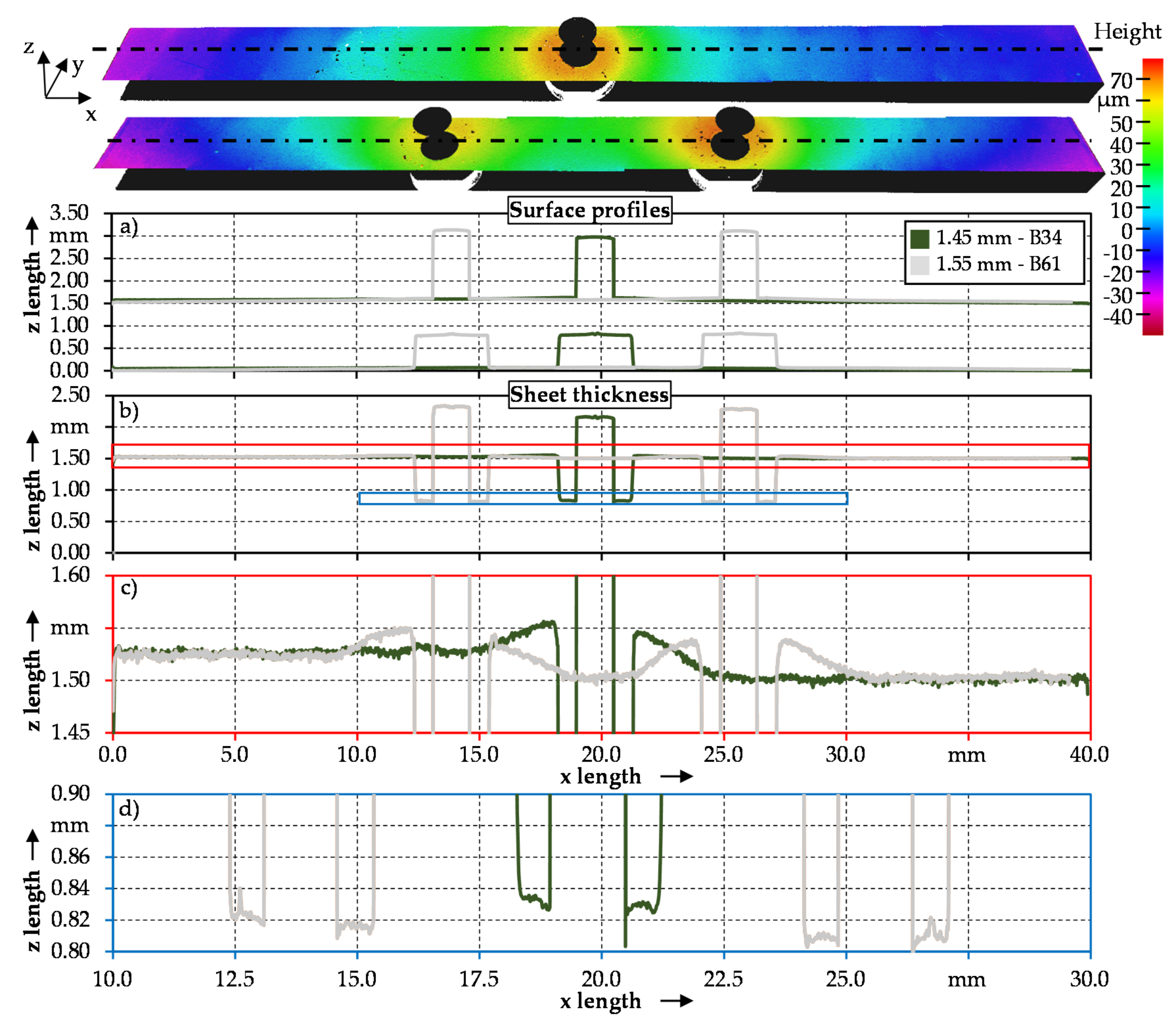
3.1. Cold Forming of Pin Structures

Table 4 shows the pin heights achieved in relation to the punch penetration depth, the number of pins and the pin arrangement. When looking at the pin heights of the single pins, a nonlinear correlation of the achieved pin height as a function of the punch penetration depth is initially noticeable (Figure 5). This observation was already scientifically documented in 2012 by Ghassemali et al. [29] for copper and is also confirmed by the results for the DP600 steel. In the investigated range of the punch penetration depth 0.61 mm ≤ s ≤ 0.88 mm, however, there is a linear relationship between the two sizes with a determination coefficient of 99.89%. Due to the relatively low standard deviation between 0.3 and 3.6%, the pin extrusion process can be rated as extremely reliable.
When extruding pin structures from the sheet metal plane, different material flows occur due to the larger punch diameter (3 mm) compared to the pin diameter (1.5 mm). Thus, there is an axial flow of the material directly above the die opening. Furthermore, there is a lateral material flow both partially into the die and into the sheet plane. In addition, the position on the sheet or the distance to the sheet edge as well as the plastification of the material by an additional pin structure have an influence on the axial and lateral portion of the material flow. When looking at the multi-pin structures, a slightly higher pin height can be observed for the same penetration depth compared to the single pin. This result seems to contradict the thesis of Kraus et al. [10]: That pins closer to the sheet edge always have a lower height at identical penetration depth than pins in the center. The hypothesis is based on the fact that the material in the indirect forming zone has a lower resistance to deformation towards the edge of the sheet.
This results from a smaller friction surface due to the small edge distance and above all from a lower reinforcing effect due to less surrounding material. On further examination, however, the results from this study with the DP600 steel do not disagree with this statement. The force–displacement curves in Figure 6 confirm the higher deformation resistance of the single pin (B34) due to the central position compared to the transversely inserted multi-pin structures (B61-1; B61-2). The maximum forming force for the single pin (B34) is 13,118 N and for the multi-pins 12,369 N (B61-2) and 12,257 N (B61-1). The increased resistance to deformation can be demonstrated in the force–displacement curve by a higher maximum force requirement of 805 N for the single pin at the same penetration depth.
The 6.6% higher maximum forming force causes an increased elastic deformation of the forming tools. In contrast to the multi pins, this results in a minimal increase in the distance between the die and the punch/blank holder as the deformation resistance increases. This causes a slight increase in the material flow in the sheet thickness direction and less into the die, which results in a decreased pin height. This hypothesis can be confirmed by the optical measurement of the sheet thickness using the optical 3D surface measuring device InfiniteFocusG5 from Alicona.
Figure 7 shows that the sheet thickness around the pin area is greater than in the edge area for both the single pin and multi-pin variants. The difference in thickness is greater for the single pin due to the described increase in distance between the die and punch/blank holder, caused by the higher deformation resistance of the material and subsequently elastic deformation of the tools. In Figure 7c, the similar sheet thickness of 1.50 mm can be measured towards the edge at a width of approximately 38 mm for both samples. However, when analyzing the sheet thickness in the area of the pin structures for both the single pin and the multi-pin specimen, the thickness of the single pin specimen is slightly higher. The multi-pin sample shows an increase in sheet thickness to an average of 1.54 mm around the right and the left pin structure. In contrast, the sheet thickness around the pin structure of the single pin sample increases to 1.55 mm and thus more strongly than the multi pins. Figure 7d, in which the sheet thickness is plotted in the direct vicinity of the pin structure, shows a similar behavior. Here, the average residual sheet thickness for the multi-pin structure is approximately 0.81 mm for the right pin and 0.82 mm for the left pin. In contrast, the residual sheet thickness for the single pin increases to approximately 0.83 mm.

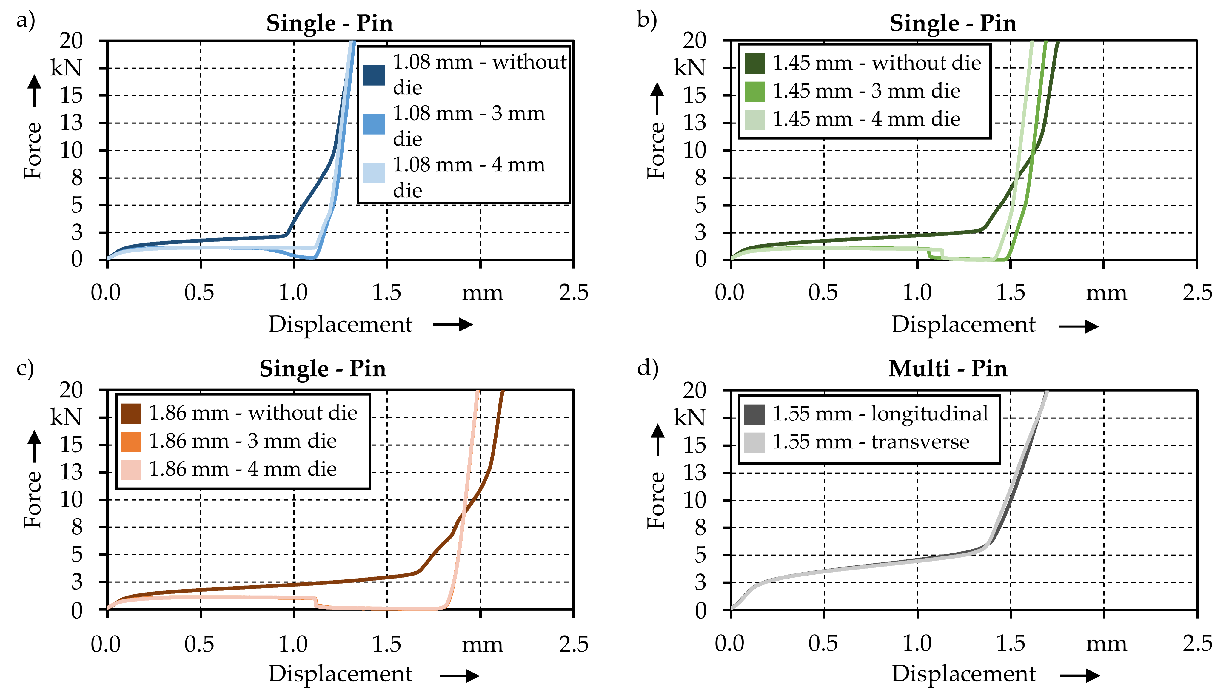
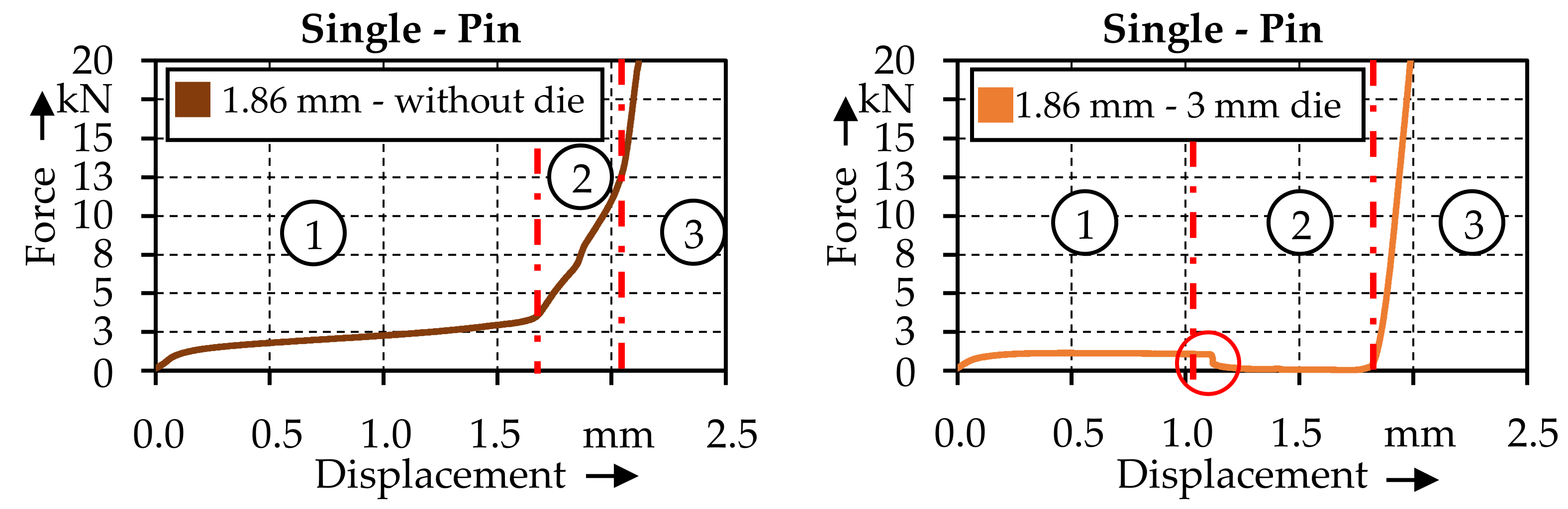
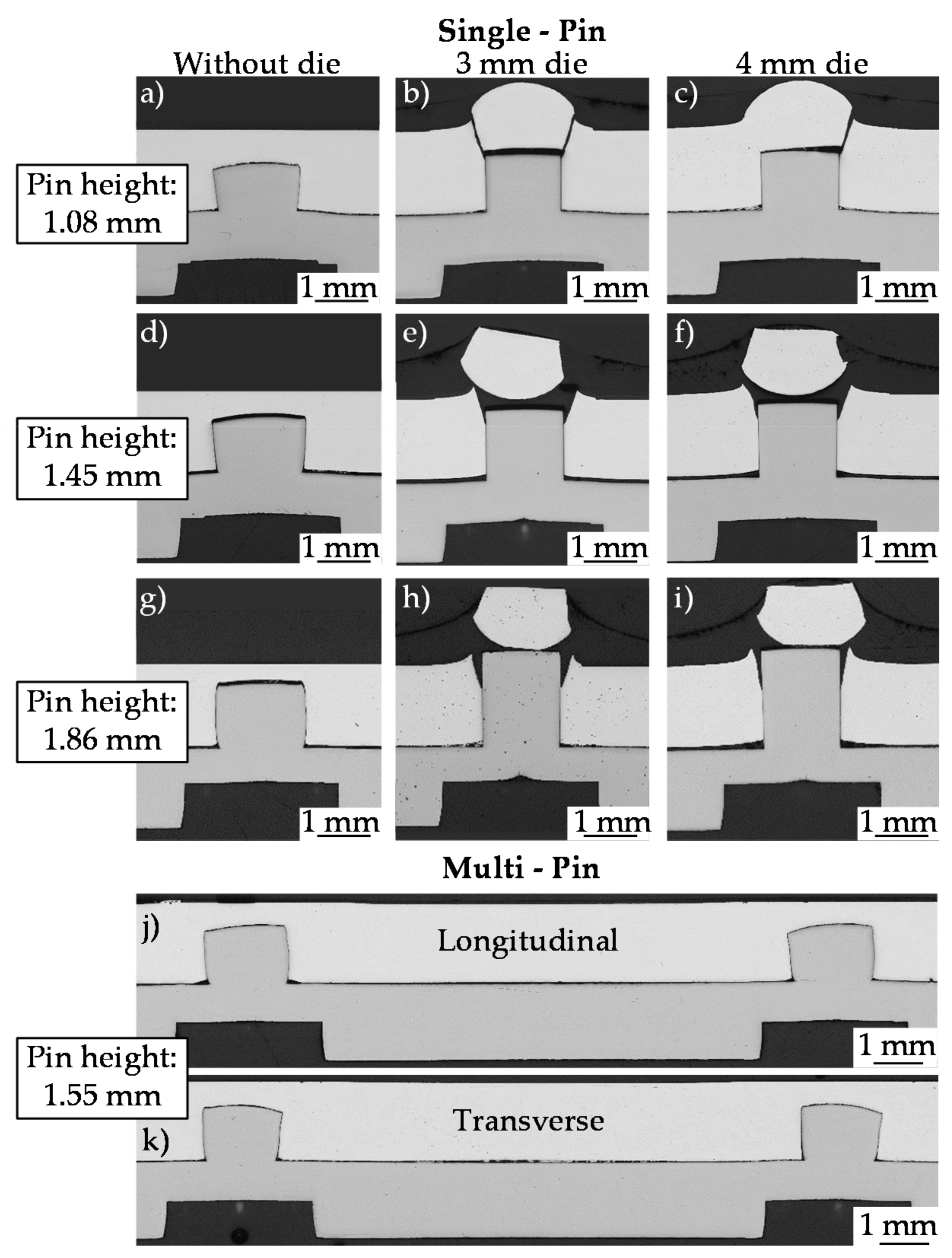
3.2. Direct Pin Pressing

The joining process plays a decisive role in the formation of a load-bearing, form-fit, and force-fit connection. In the following, the results of the direct pressing of the DP600 pin structures into the EN-AW 6014-T4 sheets are presented. A distinction is made between the different pin heights and the joining strategies. In addition, the joining process of the multi-pins is analyzed. Figure 8 shows the force–displacement curves of the examined joining strategies and the different pin heights investigated.
Regardless of the different pin heights, the comparison of the joining strategies reveals a similar behavior. Both the joining without and with die can be divided into 3 phases. For a better illustration, the three zones for the joining process without and with a 3 mm die are shown in Figure 9 using the 1.86 mm pin structures from Figure 8 as an example. Phase 1 begins with a linear increase in force while the system deforms elastically, both with and without the die. As the joining process progresses, the force increases further due to work hardening and plastic deformation. Shortly after a tool displacement of ~0.3 mm and a force of 1100 N, a plateau with a constant tool force is reached, when joining with a die. Here, the stress in the aluminium sheet introduced by the pin structure is so high that the material is axially displaced by the pin structure into the die, with the pin acting as a kind of shear punch. As the penetration of the pin structure into the aluminium sheet progresses, a slight decrease in force can be detected due to the decreasing residual sheet thickness above the pin. Phase 2 then begins with the abrupt failure of the aluminium sheet, at about 1.1 mm displacement. The force drops rapidly from 1045 N to ~270 N, then further to almost zero (Figure 9 red circle) and subsequently stays there until the tool displacement has reached the pin height. The drop in force is due to the formation of a circular crack on the surface of the aluminium sheet. The crack continues to propagate until the material has been separated completely and a circular hole has formed. For the 1.08 mm single pins, which were joined with a 4 mm die, this drop in force cannot be detected in Figure 8a. The same behavior could also be verified for another 1.08 sample joined with a 4 mm die and suggests that the residual sheet thickness of the aluminium was sufficient to absorb the prevailing stresses at the pin height of 1.08 mm. In addition, it is evident from the force–displacement curves of the other single pin specimens joined with a die that the drop of force and thus the failure of the aluminium sheet occurs generally at around 1.1 mm tool displacement. This indicates that the deformability of the aluminium sheet is at the limit for the 1.08 single pins.
However, when joining with the 3 mm die, the deformability is exhausted earlier due to the smaller die opening, which is why the aluminium sheet fails earlier at ~0.8 mm displacement and a force of 1130 N. Phase 3 then begins after the tool has been displaced by the pin height, which in Figure 9 is reached at ~1.85 mm for the specimen that was joined with a die. The aluminium sheet comes into contact with the steel sheet and the force increases linearly due to the elastic deformation of the sheet metal. In Phase 1 of the sample joined without a die, the elastic deformation is followed by an area of plastic deformation of the aluminium sheet caused by the penetrating pin structure. In contrast to the specimen joined with a die, no constant force plateau is reached. The force instead increases continuously from 1040 N and a displacement of 0.1 mm to 3200 N and a displacement of 1.6 mm (Figure 9, left). Due to the direct contact of the upsetting tool with the aluminium sheet a material flow in axial direction is restricted, which is why the material has to flow laterally into the sheet metal plane. In phase 2, a steep increase of the force to 12 kN at a displacement of 2.1 mm can be observed, which occurs due to the upsetting of the pin structure. The material of the pin is displaced in radial direction, which leads to a widening of the pin structure and subsequently to the formation of an undercut. Phase 3 begins when the aluminium sheet comes into contact with the surface of the DP600 sheet. The force increases linearly due to the elastic deformation and marks the end of the joining process.
When examining the force–displacement curve for the investigated multi-pins (Figure 8d), which were also joined without a die, a similar curve compared to the single pins (without die) can be identified. However, the force requirement increases linearly with the number of pin structures. This can be shown in comparison to the 1.45 mm sample (Figure 8b) joined without a die, which has about half the force requirement. Here phase 2 starts at around 1.3 mm displacement and a force of 3200 N compared to a displacement of 1.38 mm and force of 6336 N for the multi-pin specimen. Figure 10 shows the micrographs of the various pin-height/joint-strategy combinations (a–i) as well as the multi-pin joints (j and k). Figure 10 displays the micrographs of the various pin-height/joint-strategy combinations as well as the multi-pin joints.
For the joints shown in Figure 10a,d,g,j,k, which were all joined without a die, the upset pin structures and undercuts can be recognized. Depending on the initial pin height and the resulting compression of the pin structure, different pin geometries and undercuts are formed. For the 1.08 mm and 1.45 mm pins, a conical pin geometry can be seen in Figure 10a,d. For these, the compression of the pins is about 19% and 26%, respectively. For the multi-pins with an average pin height of 1.55 mm, the compression increases further to ~28%. Here, a transition to a barrel-shaped pin geometry can be observed. In the highest pin structures examined, with an average height of 1.86 mm, the compression is approximately 33% and a barrel-shaped pin can be observed.
In contrast to the results described above, the pin structures pressed in with a die do not show any visible compression in the micrographs and thus no formation of an undercut. This is due to the high strength gradient between the DP600 and the EN-AW 6014-T4, which is additionally increased by the strain hardening of the pin structure due to the cold forming process. Thus, for joining with a die, the strength of the aluminium sheet is not sufficient to deform the pin structures. As a consequence, the pin penetrates the aluminium sheet and displaces the material axially into the die until, depending on the pin height, the material fails and separates from the aluminium sheet. This can be clearly seen in the micrographs in Figure 10e,f,h,i, in which the separated material was also embedded. As a result, no sufficient undercut is formed. This leads to premature failure of the joined sheets as the pin is torn out of the joining partner, unlike a sufficient form fit where the joint can withstand enough load that the pin itself fails. This has a negative effect on the joint strength and could be particularly negative for the head tensile strength. In contrast to the results of the pin geometries after joining presented in this paper, Kraus et al. have demonstrated deviating pin geometries for direct pressing of cold-formed DC04 pin structures into EN-AW 6016-T4 aluminium sheet. In their work, the pin structures with a diameter of 1.32 mm and an average pin height of 1.466 mm were also joined with a die. Due to the significantly lower difference in strength between the DC04 steel and the EN-AW 6016-T4 aluminium, the strength of the aluminium is sufficient to compress the pin structure with increasing strain hardening during the pressing-in process, even when using a die. Thus, in Kraus et al. [9] a barrel-shaped pin geometry was observed at the present compression of approx. 43%.

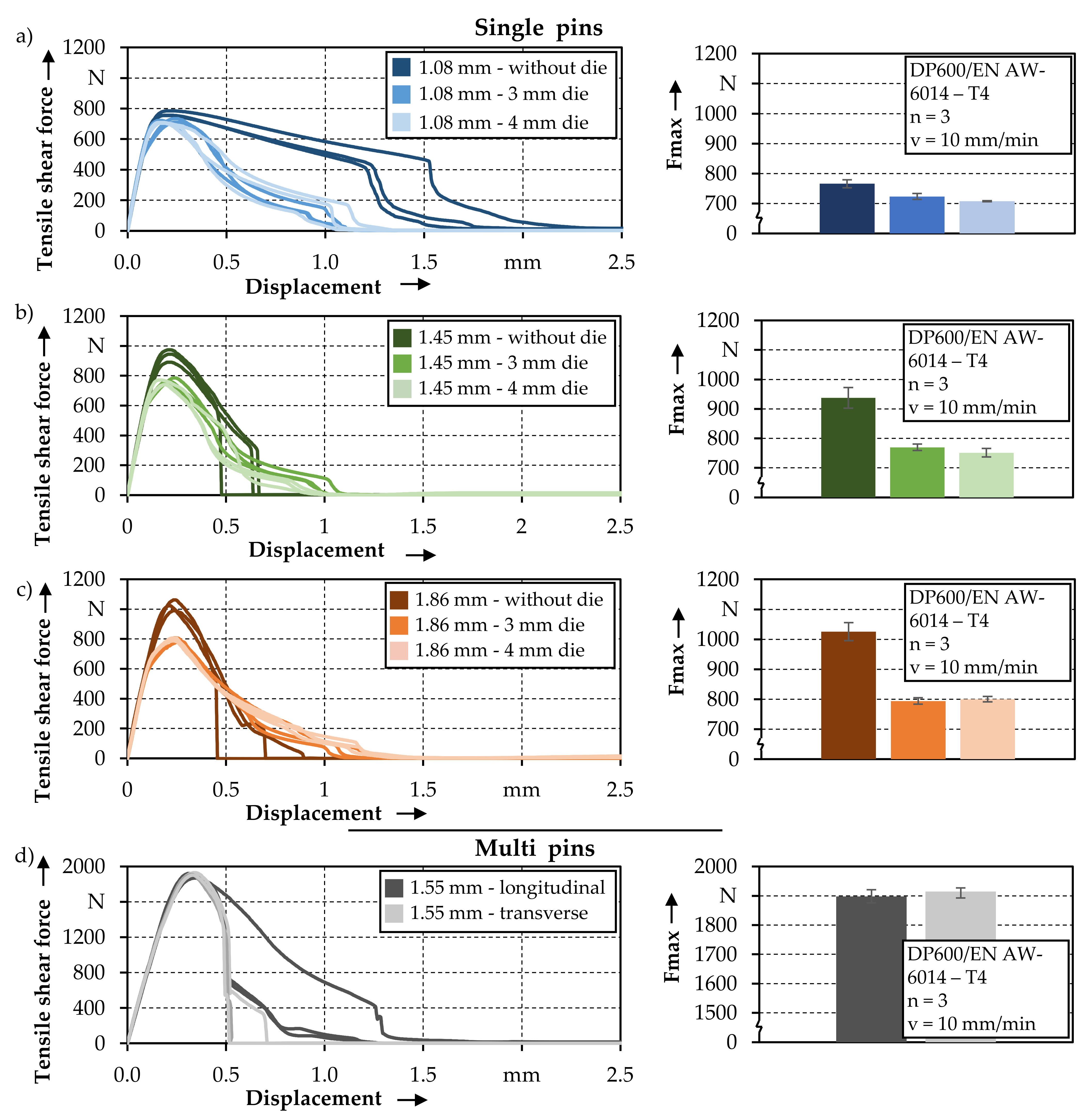
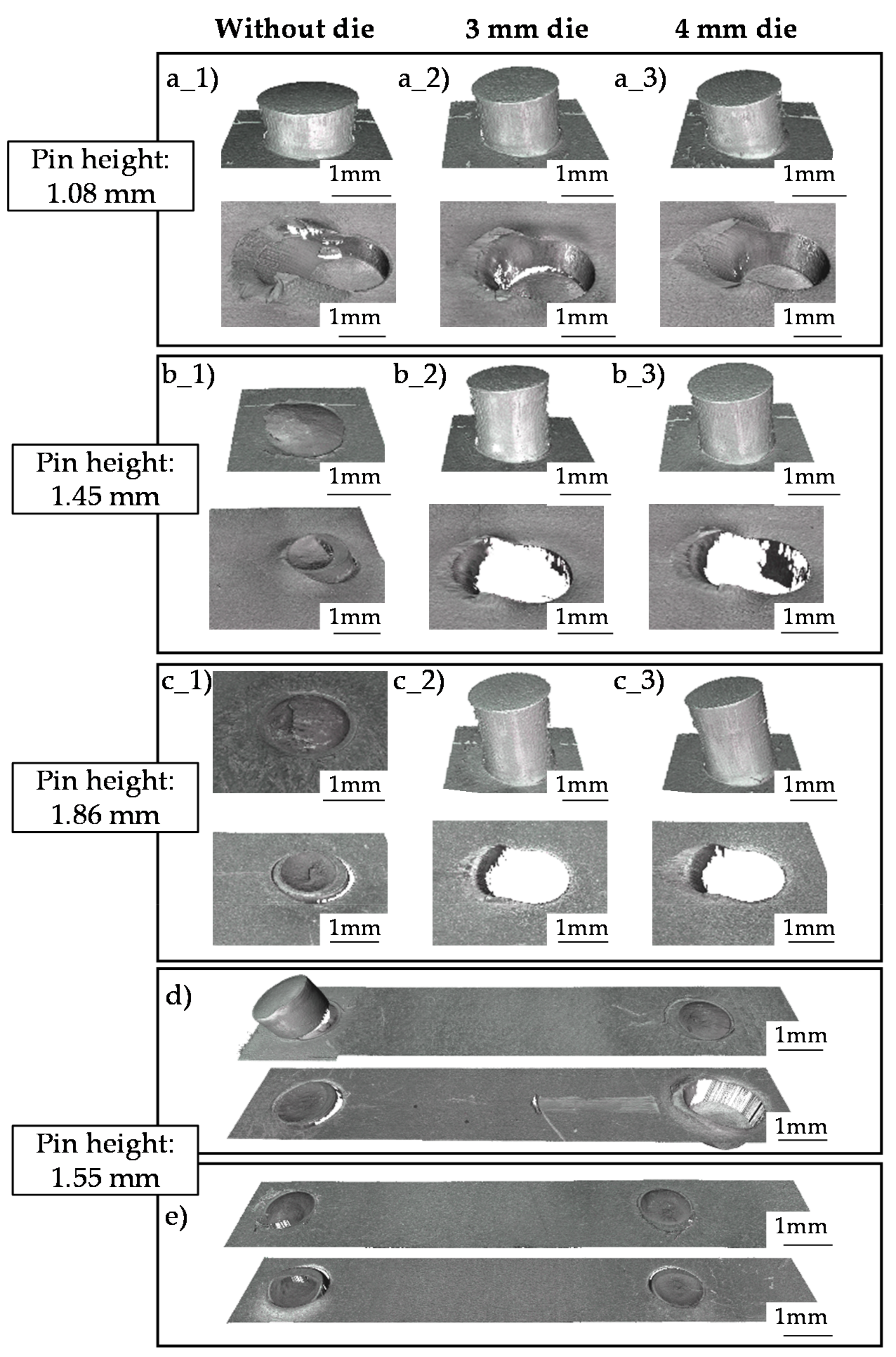
3.3. Tensile Shear Test—Characterization of the Pin Joint

The achieved tensile shear strengths of the different joints are shown in Figure 11. Regardless of the pin height, the number of pins, or the arrangement, there is initially an elastic deformation, resulting in a quick, linear increase in shear force. Due to the same material combination, the stiffness of the joints is similar. After reaching the yield stress of the soft joining partner EN AW-6014-T4, the forming force increases further due to the increasing strain hardening up to the maximum shear force. When looking at the maximum tensile shear forces achieved, it is first noticeable that the tensile shear strength increases with the height of the pin structure. For a pin height of 1.08 mm, a maximum tensile shear force of 766 ± 13 N was achieved. For a pin height of 1.45 mm, the maximum tensile shear force is 938 ± 35 N, which is 22.5% higher than the 1.08 mm specimens. By further increasing the pin height to 1.86 mm, the tensile shear strength can be increased to 1025 ± 30 N, which is 33.7% higher compared to the pin height of 1.08 mm. This increase in tensile shear strength with increasing pin height can be attributed to the improved form fit. When higher pins are inserted into the unperforated joining partner, more pin volume is compressed, which increases the maximum head diameter of the pin and thus increases the form fit. This thesis can be confirmed by measuring the head diameter from the micrographs in Figure 10. With an initial pin height of 1.08 mm, the maximum head diameter is 1.64 mm, with a pin height of 1.45 mm the diameter is 1.68 mm and with an initial pin height of 1.86 mm a 1.71 mm head diameter can be measured. The increased form fit with taller pins is also evident when looking at the damage patterns in Figure 12. With an initial pin structure of 1.08 mm Figure 12(a_1), the pin is almost undamaged after shearing. This is because the bending moment at the connection point between the pin and the sheet metal is significantly smaller than with the larger pins because of the low pin height. Due to the significantly higher strength of the DP600 pin compared to the aluminium material, combined with the lower pin height, the joining partner made of EN AW-6014-T4 is plastically deformed. After reaching the maximum tensile shear strength, the form fit is reduced due to the plastic deformation and the aluminum is grooved. With increasing shear pull, the form fit decreases continuously until the pin structure is completely pulled out of the aluminium. The higher form fit at a pin height of 1.45 mm can be verified by the damage patterns in Figure 12(b_1). Here, the aluminium joining partner is also deformed plastically at the beginning of the tensile shear test. After reaching the tensile shear strength, the force decreases continuously. This is explained by the fact that the pin structure in the joining partner is slowly sheared off as a result of the good form fit. At the same time, the cross section at the pin structure’s junction with the sheet metal continues to decrease. From a certain displacement value the pin structure is sheared off due to the reduced cross section and the associated higher stress, which is shown by a sudden drop of the force (Figure 11b).
As the sheared pin structure remains stuck in the aluminum joining partner, the form fit can be rated as very good, as only the strength of the pin influences the maximum tensile shear strength. The reason for the even higher tensile shear strength of the pin heights of 1.86 mm can also be explained by the damage patterns in Figure 12(c_1). Furthermore, here, the aluminium material is first plastically deformed until the tensile shear strength is reached. However, the deformation of the aluminium is much less than with the smaller pin heights. This is due to the fact that the higher pin structure means that the contact pressure between the pin and the aluminium in the joint is lower during the shear pull. After reaching the maximum tensile shear strength, the pin structure shears off slowly and then suddenly breaks, similar to the pin height of 1.45 mm.
Due to the lower deformation of the aluminium, the joint with the highest pin height is considered to be the most stable of the tested geometries. It can be shown that the maximum tensile shear strength of the pin structures pressed in without a die is higher than that of the samples pressed in with a die, independent of the pin height. However, the samples pressed in with die are very similar in terms of the determined tensile shear strengths. Thus, the die diameter has only a minor effect on the tensile shear strength. This is not surprising with regard to the joints depicted in Figure 10, as no compression of the pin structure can be seen, regardless of the die diameter, and the pin merely pierces the aluminium sheet. As a consequence, no undercut, which has a verifiably positive effect on the tensile shear strength, can be formed.
The difference between the specimens joined without and with a die further increases with increasing pin height. Thus, with the 1.08 mm pin structures, the tensile shear strength of the specimens joined without a die is approximately 5.9–8.3% higher than that of the specimens joined with a 3 mm or 4 mm die. In contrast, the tensile shear strength increases by 21.7–24.8% for the 1.45 mm pins and by 28.1–29.1% for the 1.86 mm pins. It can also be seen that the pin height has a significantly lower influence on the tensile shear strength for the connections joined with a die. When joined with a 3 mm die, the tensile shear strength increases by 6.3% for the 1.45 mm pins and by 9.7% for the 1.86 mm pins compared to the pin height of 1.08 mm. Using a 4 mm die, the increase is 6.2% for the 1.45 mm pins and 13.2% for the 1.86 mm high pins. The much smaller influence of the pin height on the tensile shear strength can be illustrated by the damage patterns in Figure 12 (a_2/_3, b_2/_3, c_2/_3). As the pin structure is not compressed to any significant extent due to the lower resistance to deformation, no undercut occurs during compression. As a result, the pin structure continuously slides out of the joining partner with increasing displacement. Due to the decreasing cross section, the tensile shear force decreases continuously until finally both joining partners are completely separated from each other. Despite the lower strength of the joint, the direct pressing of pins into metallic joining partners with a joining die can be of interest. The micrographs in Figure 10 have shown that there is no visible plastic deformation or even bulging of the pin structure when joining with a die. Consequently, the tensile shear strength is significantly lower. In [10], the insertion of the pin structure with die was already investigated with DC04 (joining partner with pin) and EN AW-6016-T4 (joining partner without pin) with a different material combination. Here, it has been shown that the pin, which is compressed by 43% despite the die, bulges and as a result, a form fit is achieved. Considering these results and the new findings of this article, joining by using a die opens up the potential of being able to control the form fit for different material combinations. For example, it would be possible to achieve more favorable pin structure deformation with dies for material combinations with a small difference in strength.
When looking at the multi-pin structures, it is first noticeable that the tensile shear strength can be significantly increased by adding another pin. To quantitatively evaluate the increase in strength, the maximum tensile shear strength of the multi-pin structures is compared with the single pin with 1.45 mm due to the identical penetration depth. In the longitudinal arrangement, the tensile shear strength can be increased by 102% to 1898 ± 22 N due to the additional pin, and by 104% to 1915 ± 12 N in the transverse arrangement. Taking the standard deviation into account, no influence of the arrangement on the tensile shear strength can be determined. Despite minor differences in pin height, an additional pin structure leads to a doubling of the maximum tensile shear strength. The reasons for the slightly higher pin heights of the multi-pin structures compared to the single pins at the same penetration depth have already been explained in Section 3.1. Thus, these experimental results agree with the finding in Kraus et al. [10] using a numerical substitute model that the maximum tensile shear strength increases linearly with the factor of the number of pins, proven in [10] up to a 3 × 3 pin structure, independent of the arrangement. Despite the almost identical results regarding the maximum tensile shear strength of the multi pin structures, differences in the failure of the joints can be seen when looking at the damage patterns in Figure 12d,e. For the longitudinal multi-pin specimens, it can be identified that one pin structure sheared off and got stuck in the aluminium sheet, while the other pin was torn out of the sheet. This shows severe bending and damage, which can be observed as a crack at the transition between pin and sheet. This suggests that, due to the longitudinal arrangement of the pin structures, the pin closer to the edge of the sheet experiences a higher bending during the process than the pin further away from the edge. If the first pin finally fails, the form fit is no longer sufficient to hold the pin in the joining partner due to the weakening caused by the bending moment, which is why the pin is torn out of the sheet metal and does not shear off completely. This is also reflected in the force displacement curves in Figure 11d. In contrast, for the transverse multi pin specimens, both pin structures sheared off and remained stuck in the joining partner. Due to the arrangement, both pin structures experience the same bending moment, which is why they fail in the same way. This is also reflected in the force–displacement curves, which show the abrupt drop in force in Figure 11d.

4. Conclusions and Outlook

Based on the experimental results obtained in this work, the following conclusions can be drawn:
  • Cold extrusion as a manufacturing process is suitable for the production of metallic pin structures from a higher strength DP600 steel.
  • Metallic pin structures are very suitable for joining dissimilar metals.
  • For the production of load-bearing joints, the control of the material flow during joining is essential, as a good form fit during direct pin pressing is decisive for the subsequent tensile shear strength. The form fit should withstand enough load to prevent the pin structure from being pulled out of the joining partner prematurely and that the pin itself fails instead.
  • The use of a die when joining with metallic pin structures has the potential to influence the material flow and thus the formation of the form fit. However, consideration must be given to the differences in strength of the joining partners in order to avoid the pin structure piercing the joining partner, which would lead to inferior joint quality.
  • In addition to the joining strategy, the pin structure height has a significant influence on the joint strength. With increasing pin height, the joint strength can also be increased, because the form-fit improves to such an extent that it is sufficient enough that a shearing of the pin structure is the cause of failure and thus determines the maximum joint strength. Due to the shearing of the pins, the form fit achieved by direct pin pressing without a die can be rated as very good. A further increase in the pin height only leads to a slight increase in strength.
  • By increasing the number of pins, the connection strength is increased linearly.
The future research should focus on the investigation of multi-pin structures with larger pin arrays. In this way, the results demonstrated that multi-pin structures with two pins should be verified for larger pin arrays and new insights into the joining process and the joint properties should be gained. Furthermore, the influence of different strength gradients of the joining partner materials on the joining process and here specifically on the formation of an undercut should be investigated in more detail in order to identify correlations between the joining strategies and the material flow of the pin structure and the joining partner in the joining zone during direct pin pressing.

Author Contributions

Conceptualization, D.R., M.M., and M.K.; methodology, D.R., M.M., and M.K.; investigation, D.R. and M.K.; resources, M.M.; data curation, D.R.; writing—original draft preparation, D.R. and M.K.; writing—review and editing, M.M., D.R., and M.K.; visualization, D.R.; supervision, M.M.; project administration, M.M.; funding acquisition, M.M. All authors have read and agreed to the published version of the manuscript.

Funding

This work was funded by the Deutsche Forschungsgemeinschaft (DFG, German Research Foundation)-TRR 285 C01-Project-ID 418701707.

Data Availability Statement

The data presented in this study are available on request from the corresponding author.

Conflicts of Interest

The funders had no role in the design of the study; in the collection, analyses, or interpretation of data; in the writing of the manuscript; or in the decision to publish the results.

References

  1. IEA. Global EV Outlook 2020: Entering the Decade of Electric Drive? 2020. Available online: https://www.iea.org/reports/global-ev-outlook-2020 (accessed on 10 February 2021).
  2. IEA. Electricity Information: Overview. 2020. Available online: https://www.iea.org/reports/electricity-information-overview (accessed on 10 February 2021).
  3. Smith, F. Comeld™: An Innovation in Composite to Metal Joining. Mater. Technol. 2005, 20, 91–96. [Google Scholar] [CrossRef]
  4. Parkes, P.; Butler, R.; Meyer, J.; de Oliveira, A. Static strength of metal-composite joints with penetrative reinforcement. Compos. Struct. 2014, 118, 250–256. [Google Scholar] [CrossRef] [Green Version]
  5. Thakkar, R.; Ucsnik, S. Cost efficient metal to fibre reinforced composite joining. In Proceedings of the 16th European Conference on Composite Materials, Seville, Spain, 22–26 June 2014. [Google Scholar]
  6. Plettke, R.; Schaub, A.; Gröschel, C.; Scheitler, C.; Vetter, M.; Hentschel, O.; Ranft, F.; Merklein, M.; Schmidt, M.; Drummer, D. A New Process Chain for Joining Sheet Metal to Fibre Composite Sheets. Key Eng. Mater. 2014, 611–612, 1468–1475. [Google Scholar] [CrossRef]
  7. Parkes, P.N.; Butler, R.; Almond, D.P. Growth of damage in additively manufactured metal-composite joints. In Proceedings of the ECCM15—15th European Conference on Composite Materials, Venice, Italy, 24–28 June 2012. [Google Scholar]
  8. Ucsnik, S.; Scheerer, M.; Zaremba, S.; Pahr, D. Experimental investigation of a novel hybrid metal–composite joining technology. Compos. Part A Appl. Sci. Manuf. 2010, 41, 369–374. [Google Scholar] [CrossRef]
  9. Kraus, M.; Frey, P.; Kleffel, T.; Drummer, D.; Merklein, M. Mechanical joining without auxiliary element by cold formed pins for multi-material-systems. In AIP Conference Proceedings; AIP Publishing LLC: Melville, NY, USA, 2019; Volume 2113, p. 050006. [Google Scholar] [CrossRef]
  10. Kraus, M.; Merklein, M. Potential of Joining Dissimilar Materials by Cold Formed Pin-Structures. J. Mater. Process. Technol. 2020, 283, 116697. [Google Scholar] [CrossRef]
  11. Meinhardt, M.; Endres, M.; Graf, M.; Lechner, M.; Merklein, M. Analysing resistance element welding with upset auxiliary joining steel-elements under shear load. Procedia Manuf. 2019, 29, 329–336. [Google Scholar] [CrossRef]
  12. Feistauer, E.E.; Dos Santos, J.F.; Amancio-Filho, S.T. A review on direct assembly of through-the-thickness reinforced metal–polymer composite hybrid structures. Polym. Eng. Sci. 2019, 59, 661–674. [Google Scholar] [CrossRef] [Green Version]
  13. Dance, B.G.I.; Kellar, E.J.C. Workpiece Structure Modification. U.S. Patent 7,667,158, 23 February 2010. [Google Scholar]
  14. Ferri, O.M.; Ebel, T.; de Traglia Amancio Filho, S.; Fernandez dos Santos, J. Verfahren zur Herstellung von Metallformkörpern mit Strukturierter Oberfläche; Helmholtz-Zentrum Geesthacht Zentrum für Material- und Küstenforschung GmbH: Geesthacht, Germany, 2012. [Google Scholar]
  15. Feistauer, E.; Guimarães, R.; Ebel, T.; Dos Santos, J.; Amancio-Filho, S. Ultrasonic joining: A novel direct-assembly technique for metal-composite hybrid structures. Mater. Lett. 2016, 170, 1–4. [Google Scholar] [CrossRef]
  16. Pickin, C.G.; Young, K. Evaluation of cold metal transfer (CMT) process for welding aluminium alloy. Sci. Technol. Weld. Join. 2006, 11, 583–585. [Google Scholar] [CrossRef]
  17. Selvi, S.; Vishvaksenan, A.; Rajasekar, E. Cold metal transfer (CMT) technology—An overview. Def. Technol. 2018, 14, 28–44. [Google Scholar] [CrossRef]
  18. Ucsnik, S.A.; Kirov, G. New Possibility for the Connection of Metal Sheets and Fiber Reinforced Plastics. Mater. Sci. Forum 2011, 690, 465–468. [Google Scholar] [CrossRef]
  19. Hopmann, C.; Klein, J.; Schönfuß, B.I.; Reisgen, U.; Schönberger, J.; Schiebahn, A. Analysis and specification of the crash behaviour of plastics/metal-hybrid composites by experimental and numerical methods. Prod. Eng. 2017, 11, 183–193. [Google Scholar] [CrossRef]
  20. Oluleke, R.J.; Strong, D.; Ciuca, O.P.; Meyer, J.; De Oliveira, A.; Prangnell, P.B. Mechanical and Microstructural Characterization of Percussive Arc Welded Hyper-Pins for Titanium to Composite Metal Joining. Mater. Sci. Forum 2013, 765, 771–775. [Google Scholar] [CrossRef]
  21. Papke, T.; Merklein, M. Processing of 316L hybrid parts consisting of sheet metal and additively manufactured element by Powder Bed Fusion using a laser beam. Procedia CIRP 2020, 94, 35–40. [Google Scholar] [CrossRef]
  22. Graham, D.; Rezai, A.; Baker, D.; Smith, P.; Watts, J.F. The development and scalability of a high strength, damage tolerant, hybrid joining scheme for composite–metal structures. Compos. Part A Appl. Sci. Manuf. 2014, 64, 11–24. [Google Scholar] [CrossRef] [Green Version]
  23. Byrne, G.; Dornfeld, D.; Denkena, B. Advancing Cutting Technology. CIRP Ann. 2003, 52, 483–507. [Google Scholar] [CrossRef] [Green Version]
  24. Di Giandomenico, V. Surface Structured Bonded Composite-METAL Joint. 2014. Available online: http://dspace.lib.cranfield.ac.uk/handle/1826/9308 (accessed on 12 February 2021).
  25. Kellar, E.; Smith, F. Energy absorbing joints between fibre reinforced plastics and metals. Join. Plast. 2006, 2006, 25–26. [Google Scholar]
  26. Beuth. DIN EN ISO 12996:2013-10. In Mechanisches Fügen—Zerstörende Prüfung von Verbindungen—Probenmaße und Prüfverfahren für die Scherzugprüfung von Einpunktproben (ISO_12996:2013); Deutsche Fassung EN_ISO_12996:2013; Beuth Verlag GmbH: Berlin, Germany, 2019. [Google Scholar] [CrossRef]
  27. Beuth. DIN EN ISO 6892-1:2014-06. In Metallic Materials—Tensile Testing—Part 1: Method of Test at Room Temperature (ISO 6892-1:2014), German version EN ISO 6892-1:2014 German version EN ISO 6892-1:2014; Beuth Verlag GmbH: Berlin, Germany, 2014. [Google Scholar]
  28. Römisch, D.; Kraus, M.; Merklein, M. Investigation of different joining by forming strategies when connecting different metals without auxiliary elements. Key Eng. Mater. 2021, 883, 19–26. [Google Scholar]
  29. Ghassemali, E.; Tan, M.-J.; Jarfors, A.E.W.; Lim, S.C.V. Progressive microforming process: Towards the mass production of micro-parts using sheet metal. Int. J. Adv. Manuf. Technol. 2012, 66, 611–621. [Google Scholar] [CrossRef]
Figure 1. Process schematic for extruding pin structures from the sheet metal plane.
Jmmp 05 00025 g001
Figure 2. Schematic illustration of the investigated pin arrangements.
Jmmp 05 00025 g002
Figure 3. Schematic illustration of direct pin pressing with a die.
Jmmp 05 00025 g003
Figure 4. Schematic illustration of tensile shear specimen and test setup.
Jmmp 05 00025 g004
Figure 5. Nonlinear correlation of the measured pin height to the punch penetration depth.
Jmmp 05 00025 g005
Figure 6. Force-displacement curves in relation to the number and arrangement of the pins.
Jmmp 05 00025 g006
Figure 7. Illustration of the surface profile of a single and multi-pin structure as well as the sheet thickness across the width of the sample. (a) Surface profiles of the measured specimens, (b) corresponding sheet thickness, (c) detailed view of the red area marked in subfigure (b) and (d) detailed view of the blue area marked in subfigure (b).
Jmmp 05 00025 g007
Figure 8. Force-displacement curves of the direct pin pressing joining process. (a) Force-displacement curves when joining 1.08 mm pins without and with die, (b) Force-displacement curves when joining 1.45 mm pins without and with die, (c) Force-displacement curves when joining 1.86 mm pins without and with die and (d) Force-displacement curves when joining 1.55 mm multi pin structures.
Jmmp 05 00025 g008
Figure 9. Comparison of the force displacement curves of the two investigated joining strategies based on the 1.86 mm pin structures.
Jmmp 05 00025 g009
Figure 10. Micrographs of the investigated joint variations. (a) 1.08 mm pin joined without die, (b) 1.08 mm pin joined with 3 mm die, (c) 1.08 mm pin joined with 4 mm die, (d) 1.45 mm pin joined without die, (e) 1.45 mm pin joined with 3 mm die, (f) 1.45 mm pin joined with 4 mm die, (g) 1.86 mm pin joined without die, (h) 1.86 mm pin joined with 3 mm die, (i) 1.86 mm pin joined with 4 mm die, (j) 1.55 mm longitudinal multi pins and (k) 1.55 mm transverse multi pins.
Jmmp 05 00025 g010
Figure 11. Tensile shear force–displacement curves of the investigated pin-height/joining strategy combination as well as multi pin joints. (a) Tensile shear force-displacement curves with corresponding maximum force for 1.08 mm single pins joined without and with die, (b) tensile shear force-displacement curves with corresponding maximum force for 1.45 mm single pins joined without and with die, (c) tensile shear force-displacement curves with corresponding maximum force for 1.86 mm single pins joined without and with die and (d) tensile shear force-displacement curves with corresponding maximum force for 1.55 mm multi pins.
Jmmp 05 00025 g011
Figure 12. Damage patterns of the examined joints with steel sheet containing the pin structure at the top and corresponding aluminium sheet at the bottom. (a_1) 1.08 mm pin joined without die, (a_2) 1.08 mm pin joined with 3 mm die, (a_3) 1.08 mm pin joined with 4 mm die, (b_1) 1.45 mm pin joined without die, (b_2) 1.45 mm pin joined with 3 mm die, (b_3) 1.45 mm pin joined with 4 mm die, (c_1) 1.86 mm pin joined without die, (c_2) 1.86 mm pin joined with 3 mm die, (c_3) 1.86 mm pin joined with 4 mm die, (d) 1.55 mm longitudinal multi pins and (e) 1.55 mm transverse multi pins.
Jmmp 05 00025 g012
Table 1. Chemical composition of HCT590X + Z and EN AW-6014-T4 in weight-%.
MaterialCSiMnPSAltotalCr+MoNb+Ti
HCT590X + Zmax.
0.15
max.
0.75
max.
2.5
max.
0.04
max.
0.015
0.015–1.5max.
1.4
max.
0.15
SiFeCuMnMgCrZnTiVOthers
Each
Others
Total
EN AW-60140.3–0.6max.
0.35
max.
0.25
0.05–0.20.4–0.8max.
0.2
max.
0.1
max.
0.1
max.
0.1
max.
0.05
max.
0.15
Table 2. Mechanical material properties of HCT590X + Z and EN AW-6014-T4 as obtained from the uniaxial tensile test in rolling direction with a number of tests per material of n = 3.
HCT590X + ZEN AW-6014–T4
Yield Strength ys [MPa]397.3 ± 1.7137.8 ± 0.8
Tensile Strength ts [MPa]610.8 ± 1.5245.7 ± 0.6
Sheet thickness t0 [mm]1.51.5
Table 3. Relevant process parameters of the cold forming process for the pin structures.
Cold Forming and Joining of Pin Structures
(a) Constant Process Parameters
Punch diameter dP (mm)3
Punch speed vP (mm/min)5
Blank holder pressure σBH (MPa)250
Die diameter for forming dD (mm)1.5
(b) Varied Process Parameter
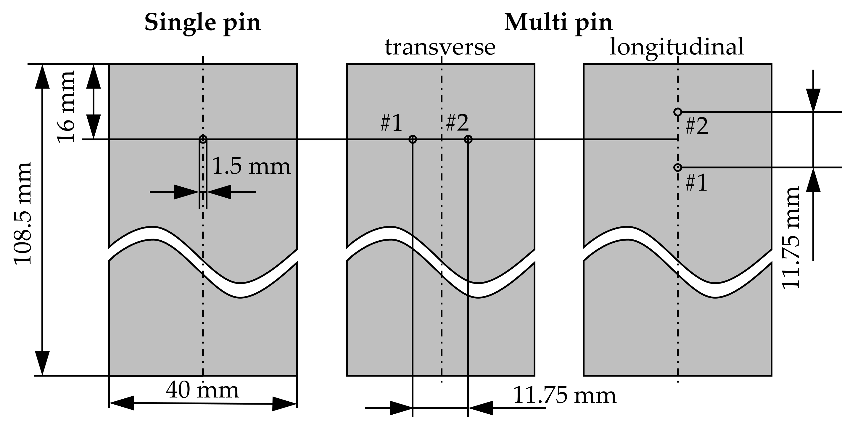
Classification (see Figure 2)LabelPin arrangement
(see Figure 2)
Punch penetration depth s (mm)Die diameter dDPP for (joining) (mm)
Single pins1.08 mm-0.610 ± 0.0030, 3, 4
1.45 mm-0.743 ± 0.0050, 3, 4
1.86 mm-0.879 ± 0.0090, 3, 4
Multi pins1.55 mmLongitudinal0.748 ± 0.0030
0.785 ± 0.0080
Transverse0.746 ± 0.0050
Table 4. Achieved pin height in relation to punch penetration depth, number of pins, and pin arrangement.
ClassificationLabelPin Arrangement (see Figure 2)Pin Position (see Figure 2)Punch Penetration Depth [mm]Pin Height [mm]Number of Tests n
Single pin1.08 mm-#10.61 ± 0.001.08 ± 0.019
Single pin1.45 mm-#10.74 ± 0.011.45 ± 0.059
Single pin1.86 mm-#10.88 ± 0.011.86 ± 0.049
Multi pin1.55 mmLongitudinal#10.75 ± 0.001.54 ± 0.013
Multi pin1.55 mmLongitudinal#20.79 ± 0.011.56 ± 0.013
Multi pin1.55 mmTransversal#1 + #20.75 ± 0.011.53 ± 0.026
Publisher’s Note: MDPI stays neutral with regard to jurisdictional claims in published maps and institutional affiliations.

