
Experimental and Numerical Investigations into Magnetic Pulse Welding of Aluminum Alloy 6016 to Hardened Steel 22MnB5

 ,
,  ,
,
Abstract
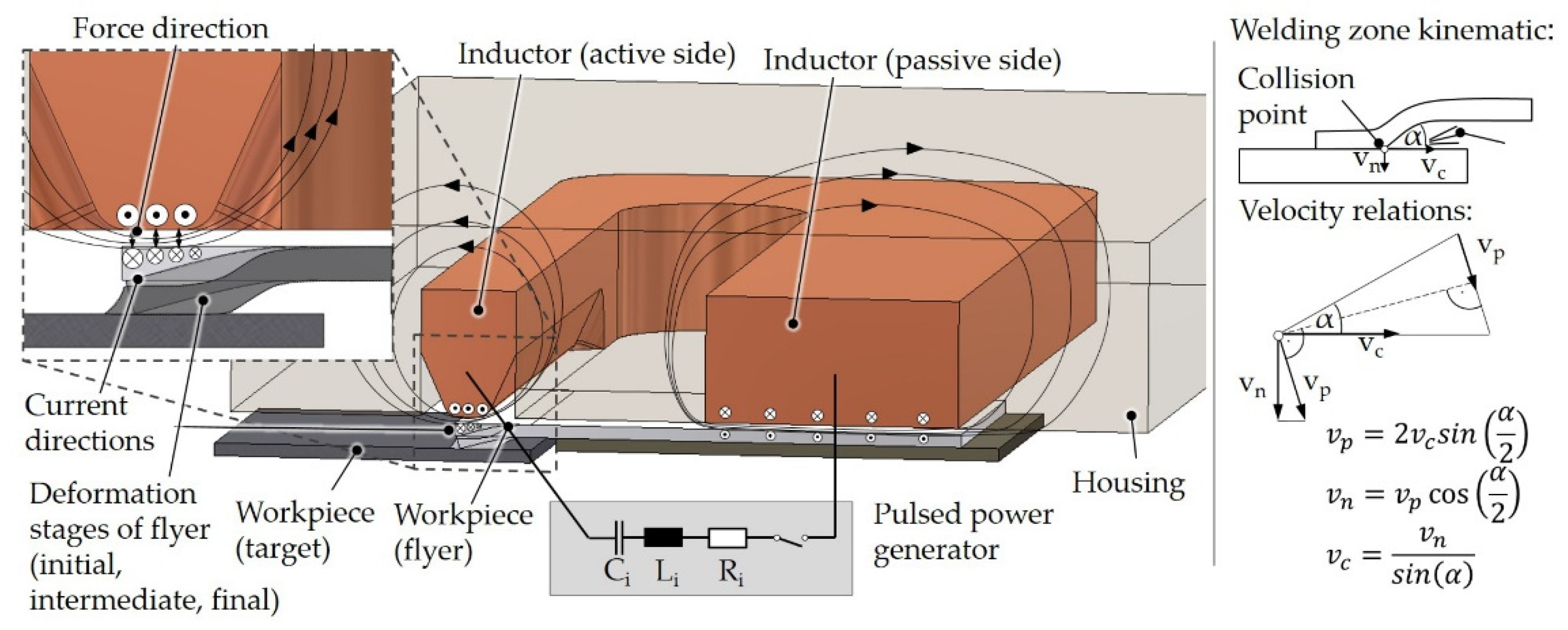
:1. Introduction
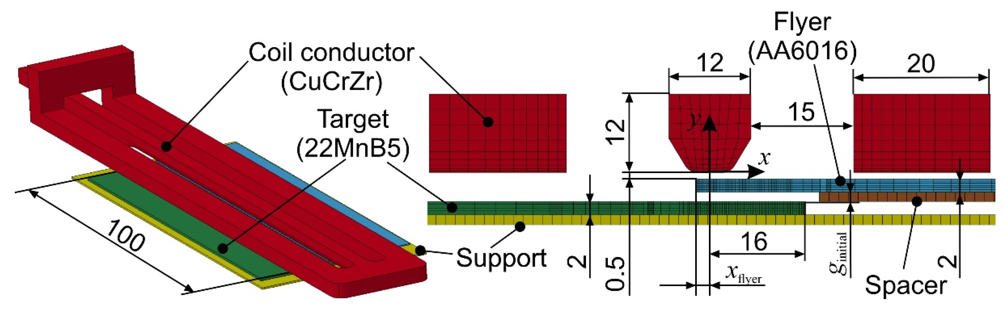
2. Materials and Methods
3. Results and Discussion
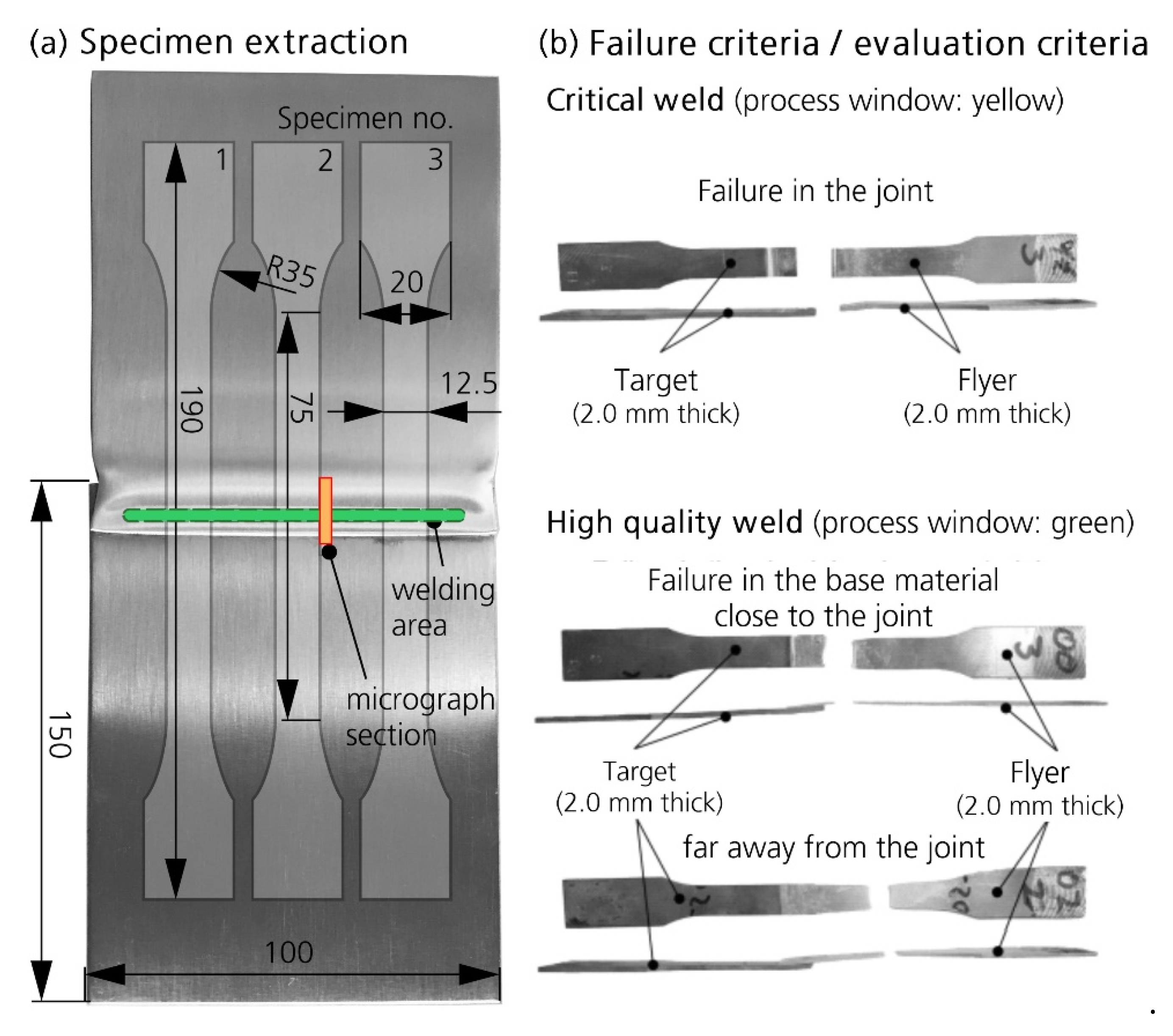
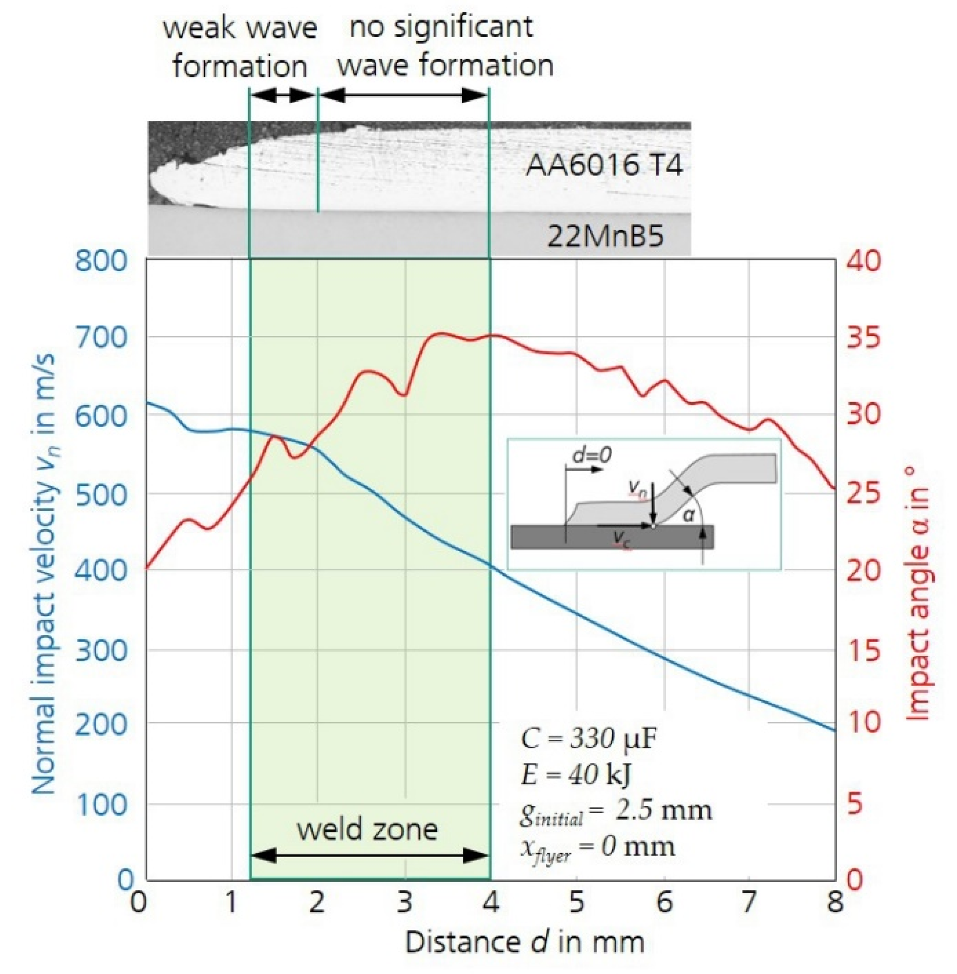
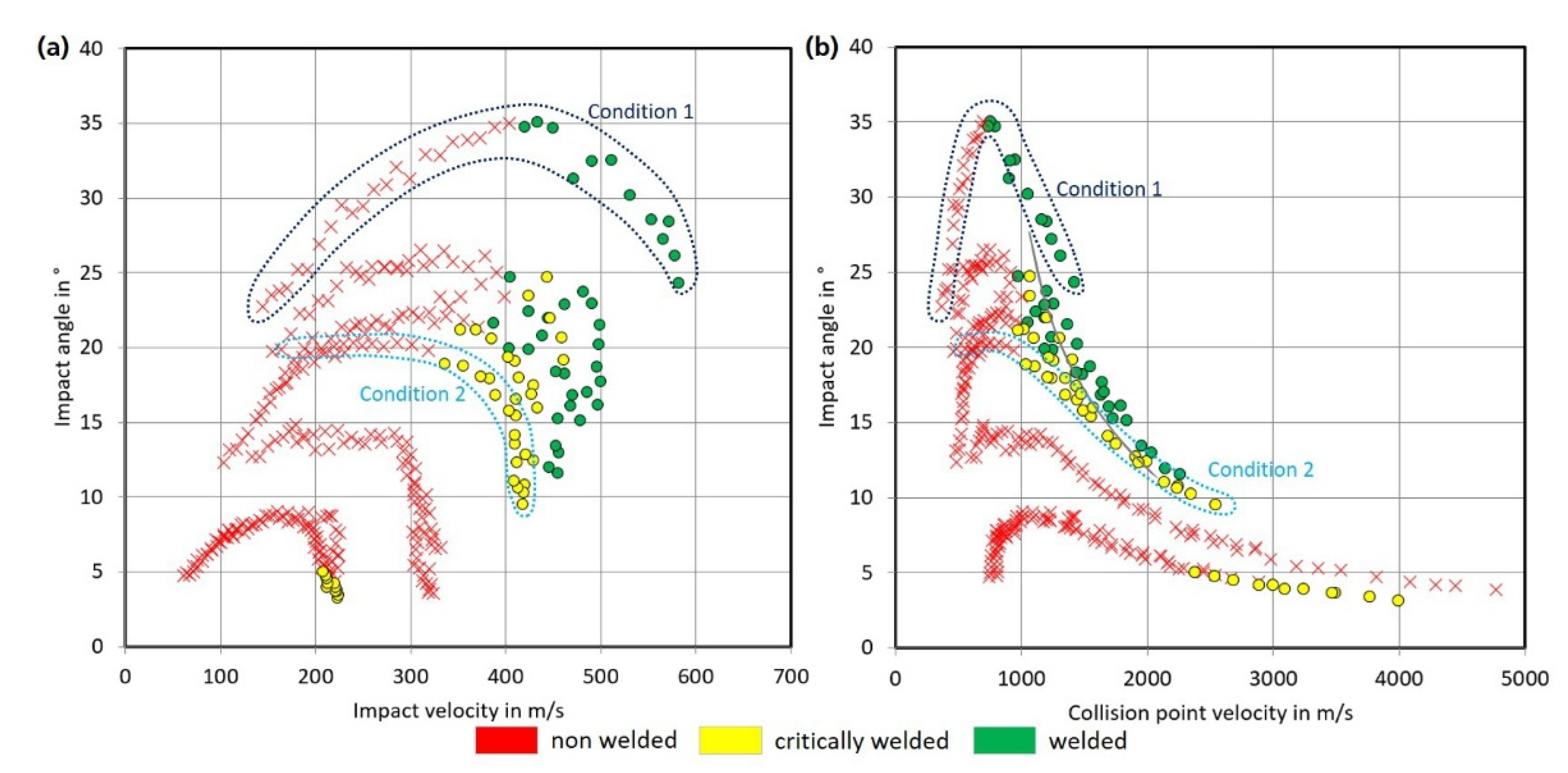
3.1. Determination of MPW Process Window
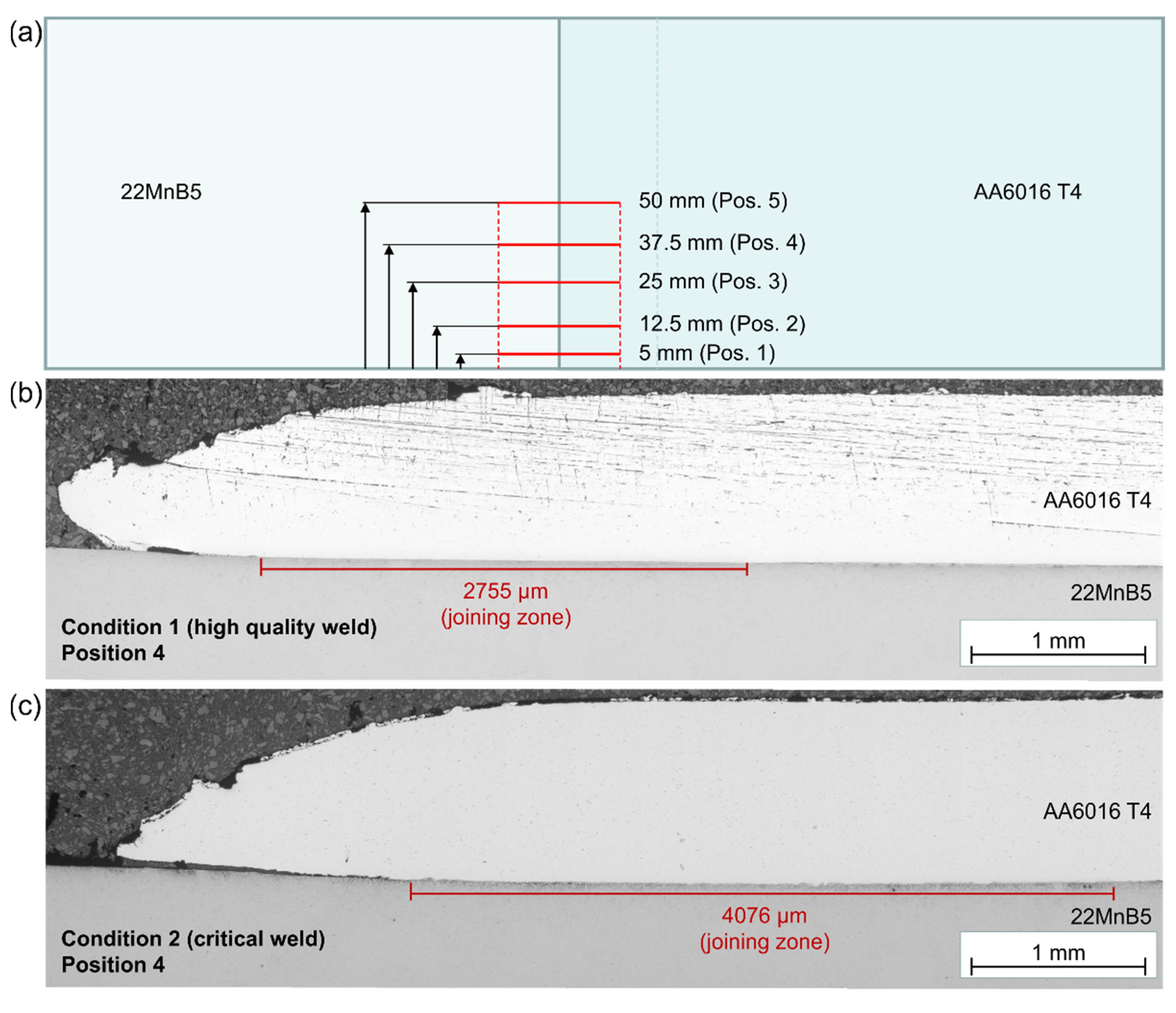
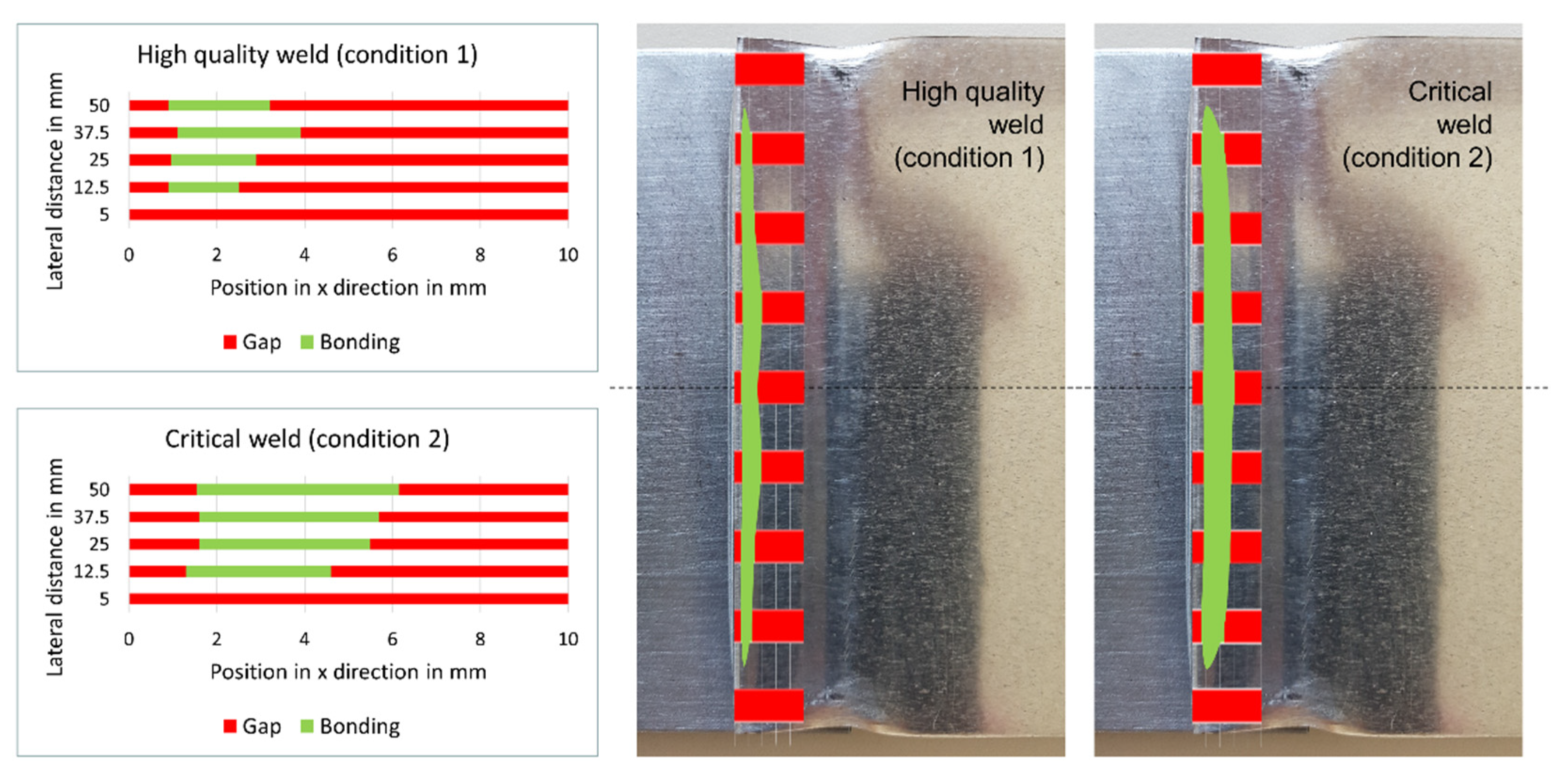
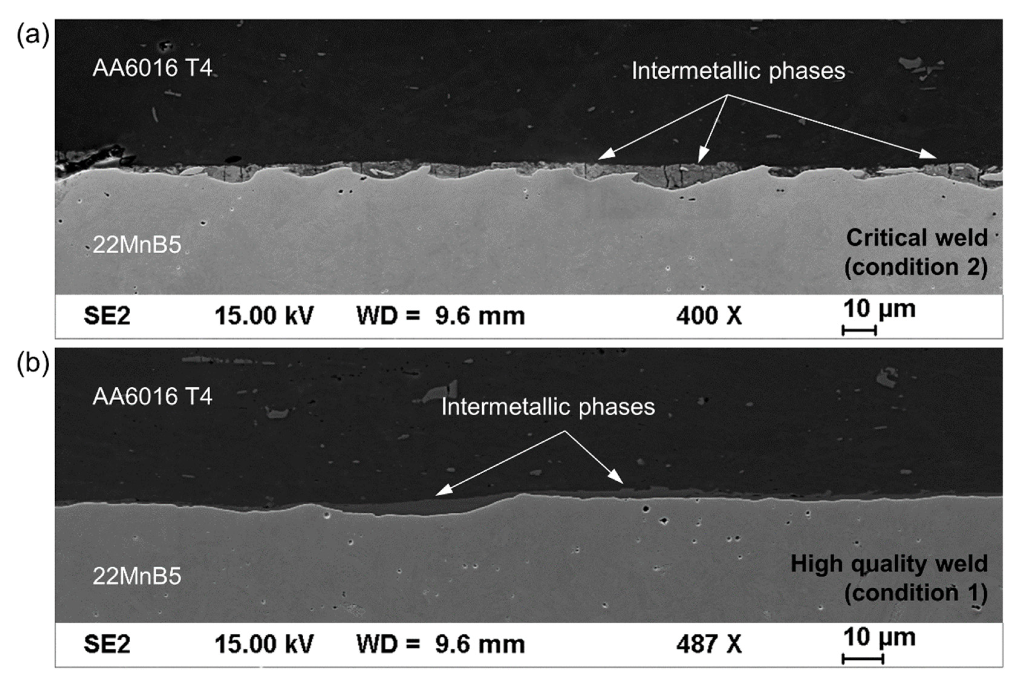
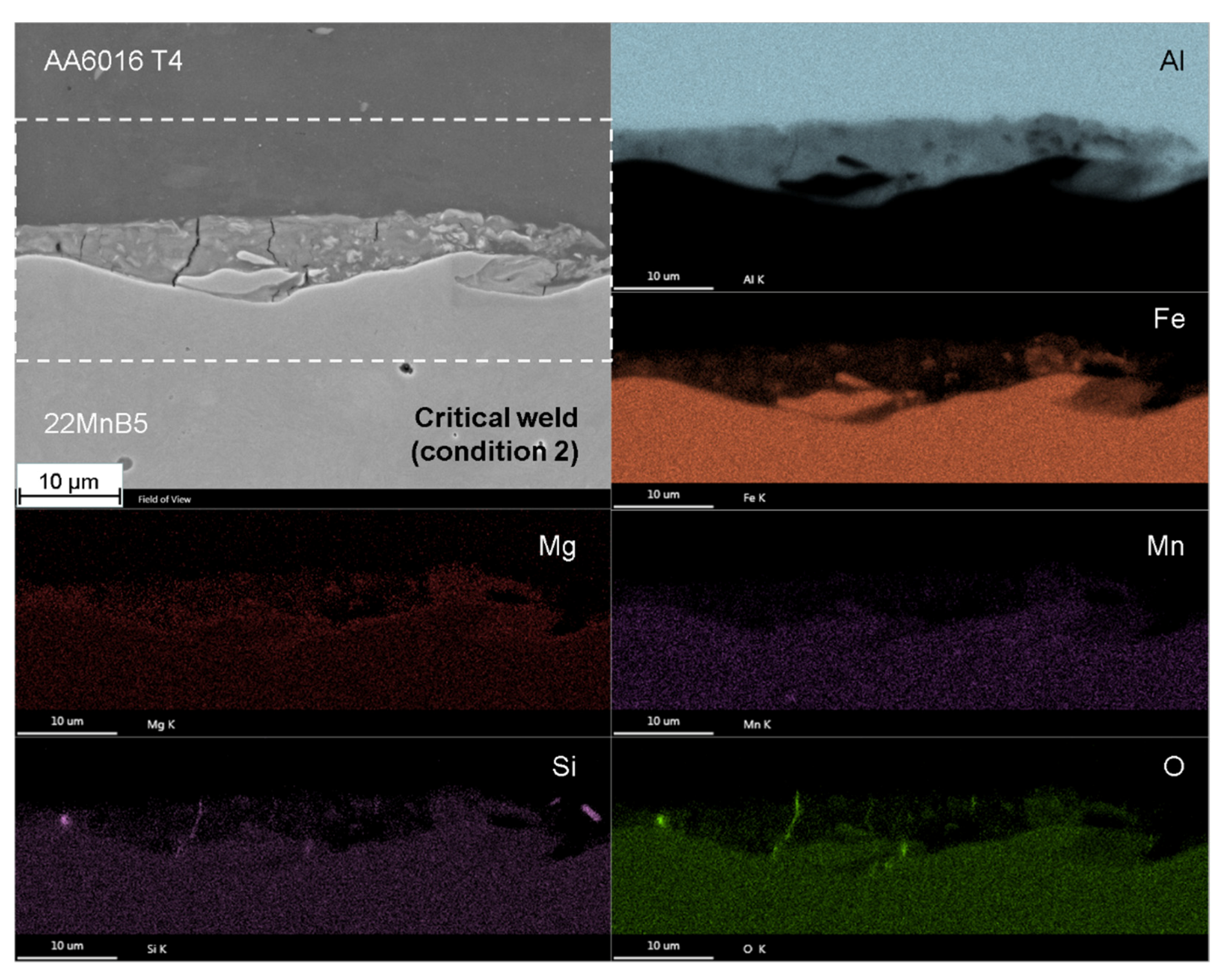
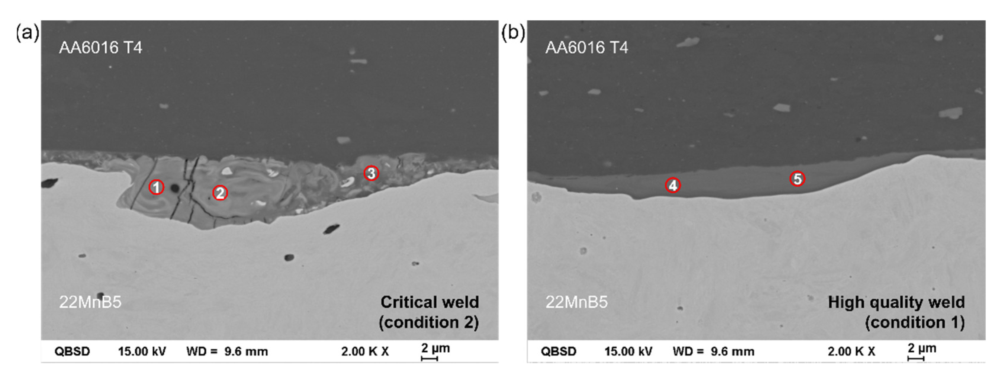
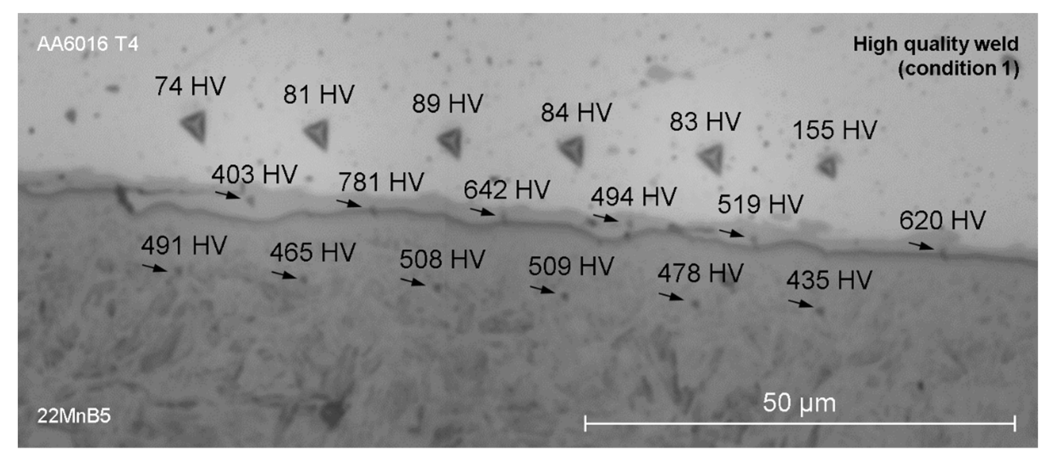
3.2. Detailed Microstructural Characterization
4. Summary and Conclusions
- For the first time, the aluminum alloy AA6016 was successfully joined to hardened steel 22MnB5 by MPW.
- A robust process window for high-quality welds was determined by a macroscopic coupled multiphysics simulation in LS-DYNA.
- Surprisingly, the high-quality welds were characterized by thinner, but very homogeneous and crack-free transition zones consisting of an Al-rich intermetallic phase.
Author Contributions
Funding
Data Availability Statement
Acknowledgments
Conflicts of Interest
References
- Lysenko, D.N.; Ermolaev, V.V.; Dudin, A.A. Method of Pressure Welding. U.S. Patent US3520049A, 14 July 1970. [Google Scholar]
- Aizawa, T.; Kashani, M.; Okagawa, K. Application of magnetic pulse welding for aluminum alloys and SPCC steel sheet joints. Weld. J. 2007, 86, 119–124. [Google Scholar]
- Psyk, V.; Risch, D.; Kinsey, B.L.; Tekkaya, A.E.; Kleiner, M. Electromagnetic forming—A review. J. Mater. Process. Technol. 2011, 211, 787–829. [Google Scholar] [CrossRef]
- Davies, R.; Austin, E.R. Electromagnetic Forming: Developments in High Speed Metal Forming; Industrial Press: New York, NY, USA, 1970. [Google Scholar]
- Pereira, D.; Oliveira, J.P.; Pardal, T.; Miranda, R.M.; Santos, T.G. Magnetic pulse welding: Machine optimisation for aluminium tubular joints production. Sci. Technol. Weld. Join. 2018, 23, 172–179. [Google Scholar] [CrossRef]
- Psyk, V.; Linnemann, M.; Sebastiani, G. 4-Electromagnetic pulse forming. In Elsevier Series in Mechanics of Advanced Materials; Silberschmidt, V., Böhlke, T., McDowell, D., Zhong, C., Eds.; Elsevier: Amsterdam, The Netherlands, 2020; pp. 111–142. [Google Scholar]
- Xu, J.; Wang, Y.; Wen, Z.; Li, Y.; Yan, L.; Cui, J. Electromagnetic impacting medium forming (EIMF): A new method forming process for magnesium alloy sheet. Int. J. Adv. Manuf. Technol. 2020, 109, 553–563. [Google Scholar] [CrossRef]
- Psyk, V.; Scheffler, C.; Tulke, M.; Winter, S.; Guilleaume, C.; Brosius, A. Determination of Material and Failure Characteristics for High-Speed Forming via High-Speed Testing and Inverse Numerical Simulation. J. Manuf. Mater. Process. 2020, 4, 31. [Google Scholar] [CrossRef] [Green Version]
- Lueg-Althoff, J.; Lorenz, A.; Gies, S.; Weddeling, C.; Goebel, G.; Tekkaya, A.E.; Beyer, E. Magnetic pulse welding by electromagnetic compression: Determination of the impact velocity. Adv. Mater. Res. 2014, 966–967, 489–499. [Google Scholar] [CrossRef]
- Shanthala, K.; Sreenivasa, T.N.; Choudhury, H.; Dond, S.; Sharma, A. Analytical, numerical and experimental study on joining of aluminium tube to dissimilar steel rods by electro magnetic pulse force. J. Mech. Sci. Technol. 2018, 32, 1725–1732. [Google Scholar] [CrossRef]
- Psyk, V.; Lieber, T.; Kurka, P.; Drossel, W.G. Electromagnetic joining of hybrid tubes for hydroforming. Procedia CIRP 2014, 23, 1–6. [Google Scholar] [CrossRef]
- Kore, S.D.; Date, P.P.; Kulkarni, S.V. Electromagnetic impact welding of aluminum to stainless steel sheets. J. Mater. Process. Technol. 2008, 208, 486–493. [Google Scholar] [CrossRef]
- Schäfer, R.; Pasquale, P. Robot automated EMPT sheet welding. In Proceedings of the 5th International Conference on High Speed Forming (ICHSF 2012), Dortmund, Germany, 24–26 April 2012; pp. 189–196. [Google Scholar]
- Faes, K.; Shotri, R.; De, A. Probing Magnetic Pulse Welding of Thin-Walled Tubes. J. Manuf. Mater. Process. 2020, 4, 118. [Google Scholar] [CrossRef]
- Khalil, C.; Marya, S.; Racineux, G. Magnetic Pulse Welding and Spot Welding with Improved Coil Effciency-Application for DissimilarWelding of Automotive Metal Alloys. J. Manuf. Mater. Process. 2020, 4, 69. [Google Scholar] [CrossRef]
- Beerwald, C.; Beerwald, H. Spiralförmige Spule zur magnetischen Umformung von Blechen. Patent DE10207655A1, 16 September 2010. [Google Scholar]
- Psyk, V.; Beerwald, C.; Henselek, A.; Homberg, W.; Brosius, A.; Kleiner, M. Integration of Electromagnetic Calibration into the Deep Drawing Process of an Industrial Demonstrator Part. Key Eng. Mater. 2007, 344, 435–442. [Google Scholar] [CrossRef]
- Psyk, V. Prozesskette Krümmen—Elektromagnetisch Komprimieren—Innenhochdruckumformen für Rohre und Profilförmige Bauteile; Shaker: Dortmund, Germany, 2010. [Google Scholar]
- Kwee, I.; Psyk, V.; Faes, K. Effect of the Welding Parameters on the Structural and Mechanical Properties of Aluminium and Copper Sheet Joints by Electromagnetic Pulse Welding. World J. Eng. Technol. 2016, 4, 538–561. [Google Scholar] [CrossRef] [Green Version]
- Psyk, V.; Scheffler, C.; Linnemann, M.; Landgrebe, D. Manufacturing of hybrid aluminum copper joints by electromagnetic pulse welding—Identification of quantitative process windows. AIP Conf. Proc. 2017, 1896, 110001. [Google Scholar] [CrossRef]
- Ben-Artzy, A.; Stern, A.; Frage, N.; Shribman, V.; Sadot, O. Wave formation mechanism in magnetic pulse welding. Int. J. Impact Eng. 2010, 37, 397–404. [Google Scholar] [CrossRef]
- Cai, W.; Daehn, G.; Vivek, A.; Li, J.; Khan, H.; Mishra, R.; Komarasamy, M. A State-of-the-Art Review on Solid-State Metal Joining. J. Manuf. Sci. Eng. 2019, 141, 031012. [Google Scholar] [CrossRef]
- Kang, B.-Y. Review of magnetic pulse welding. J. Weld. Join. 2015, 33, 7–13. [Google Scholar] [CrossRef] [Green Version]
- Raoelison, R.N.; Sapanathan, T.; Buiron, N.; Rachik, M. Magnetic pulse welding of Al/Al and Al/Cu metal pairs: Consequences of the dissimilar combination on the interfacial behavior during the welding process. J. Manuf. Process. 2015, 20, 112–127. [Google Scholar] [CrossRef]
- Wu, X.; Shang, J. An Investigation of Magnetic Pulse Welding of Al/Cu and Interface Characterization. J. Manuf. Sci. Eng. 2014, 136, 051002. [Google Scholar] [CrossRef]
- Kochan, A. Magnetic pulse welding shows potential for automotive applications. Assem. Autom. 2000, 20, 129–132. [Google Scholar] [CrossRef]
- Kimchi, M.; Shao, H.; Cheng, W.; Krishnaswamy, P. Magnetic pulse welding aluminium tubes to steel bars. Weld. World 2004, 48, 19–22. [Google Scholar] [CrossRef]
- Yu, H.; Xu, Z.; Fan, Z.; Zhao, Z.; Li, C. Mechanical property and microstructure of aluminum alloy-steel tubes joint by magnetic pulse welding. Mater. Sci. Eng. A 2013, 561, 259–265. [Google Scholar] [CrossRef]
- Psyk, V.; Scheffler, C.; Linnemann, M.; Landgrebe, D. Process analysis for magnetic pulse welding of similar and dissimilar material sheet metal joints. Procedia Eng. 2017, 207, 353–358. [Google Scholar] [CrossRef]
- Wang, S.; Zhou, B.; Zhang, X.; Sun, T.; Li, G.; Cui, J. Mechanical properties and interfacial microstructures of magnetic pulse welding joints with aluminum to zinc-coated steel. Mater. Sci. Eng. A 2020, 788, 139425. [Google Scholar] [CrossRef]
- Psyk, V.; Linnemann, M.; Scheffler, C. Experimental and numerical analysis of incremental magnetic pulse welding of dissimilar sheet metals. Manuf. Rev. 2019, 6, 7. [Google Scholar] [CrossRef] [Green Version]
- Cuq-Lelandais, J.-P.; Avrillaud, G.; Ferreira, S.; Mazars, G.; Nottebaert, A.; Teilla, G.; Shribman, V. 3D Impacts Modeling of the Magnetic Pulse Welding Process and Comparison to Experimental Data. In Proceedings of the 7th International Conference on High Speed Forming, Dortmund, Germany, 27–28 April 2016; pp. 13–22. [Google Scholar]
- Vogel, M.; Lechner, M. Manufacturing of process adapted tailored blanks by flexible rolling process using aluminum alloy AA6016. Procedia Manuf. 2018, 15, 1224–1231. [Google Scholar] [CrossRef]
- Karbasian, H.; Tekkaya, A.E. A review on hot stamping. J. Mater. Process. Technol. 2010, 210, 2103–2118. [Google Scholar] [CrossRef]
- Basaran, M. Stress State Dependent Damage Modeling with a Focus on the Lode Angle Influence; Shaker: Aachen, Germany, 2011. [Google Scholar]
- Topic, I.; Höppel, H.W.; Göken, M. Friction stir welding of accumulative roll-bonded commercial-purity aluminium AA1050 and aluminium alloy AA6016. Mater. Sci. Eng. A 2009, 503, 163–166. [Google Scholar] [CrossRef]
- Bok, H.-H.; Kim, S.N.; Suh, D.W.; Barlat, F.; Lee, M.-G. Non-isothermal kinetics model to predict accurate phase transformation and hardness of 22MnB5 boron steel. Mater. Sci. Eng. A 2015, 626, 67–73. [Google Scholar] [CrossRef]
- Aziz, N.; Aqida, S.N. Optimization of quenching process in hot press forming of 22MnB5 steel for high strength properties. IOP Conf. Series Mater. Sci. Eng. 2013, 50, 012064. [Google Scholar] [CrossRef] [Green Version]
- Matysik, P.; Jóźwiak, S.; Czujko, T. Characterization of low-symmetry structures from phase equilibrium of Fe-Al system—Microstructures and mechanical properties. Materials 2015, 8, 914–931. [Google Scholar] [CrossRef] [PubMed]
- Potesser, M.; Schoeberl, T.; Antrekowitsch, H.; Bruckner, J. The characterization of the intermetallic Fe-Al layer of steel-aluminum weldings. In Proceedings of the TMS Annual Meeting & Exhibition, San Antonio, TX, USA, 12–16 March 2006; pp. 167–176. [Google Scholar]


| Al | Fe | Mn | Si | Mg | |
|---|---|---|---|---|---|
| AA6016 | 97.6 | 0.4 | 0.1 | 0.6 | 1.3 |
| 22MnB5 | 0.1 | 98.2 | 1.4 | 0.3 | - |
| Generator Parameters | |
|---|---|
| Capacitor charging energy E | 30–40 kJ |
| Capacitance C | 330 µF |
| Tool parameter | |
| Active length of inductor lactive | 100 mm |
| Workpiece parameters | |
| Flyer thickness tflyer | 2 mm |
| Target thickness ttarget | 2 mm |
| Width of flyer and target | 100 mm |
| Experimental setup parameters | |
| Initial gap flyer to target ginitial | 0.5–2.5 mm |
| x-position of flyer edge xflyer | −3–0 mm |
| x-position of target edge xtarget | fixed to 14 mm |
| free length l | fixed to 16 mm |
| Maximum Force F in N | Displacement at F in mm | Failure Mode | |
|---|---|---|---|
| Condition 1 E = 40 kJ ginitial = 2.5 mm xflyer = 0 mm | 2813 ± 73 | 5.11 ± 0.31 | high-quality weld (fail in base material) |
| Condition 2 E = 35 kJ ginitial = 1.5 mm xflyer = −2 mm | 1898 ± 56 | 1.86 ± 0.18 | critical weld (fail in joint) |
| Element | Al | Fe | Mg | Si | Mn | ||||||
|---|---|---|---|---|---|---|---|---|---|---|---|
| wt.% | at.% | wt.% | at.% | wt.% | at.% | wt.% | at.% | wt.% | at.% | ||
| Critical weld | Spot 1 | 60.8 | 75.5 | 37.3 | 22.4 | 0.7 | 1.0 | 0.7 | 0.8 | 0.5 | 0.3 |
| Spot 2 | 52.5 | 69.0 | 45.6 | 29.0 | 0.6 | 0.8 | 0.6 | 0.8 | 0.7 | 0.4 | |
| Spot 3 | 81.5 | 89.2 | 16.7 | 8.8 | 0.8 | 1.0 | 0.7 | 0.8 | 0.3 | 0.2 | |
| High-quality weld | Spot 4 | 79.6 | 87.9 | 18.2 | 9.7 | 1.1 | 1.4 | 0.7 | 0.8 | 0.4 | 0.2 |
| Spot 5 | 79.6 | 88.0 | 18.3 | 9.8 | 1.0 | 1.3 | 0.7 | 0.7 | 0.4 | 0.2 | |
Publisher’s Note: MDPI stays neutral with regard to jurisdictional claims in published maps and institutional affiliations. |
© 2021 by the authors. Licensee MDPI, Basel, Switzerland. This article is an open access article distributed under the terms and conditions of the Creative Commons Attribution (CC BY) license (https://creativecommons.org/licenses/by/4.0/).
Share and Cite
Drehmann, R.; Scheffler, C.; Winter, S.; Psyk, V.; Kräusel, V.; Lampke, T. Experimental and Numerical Investigations into Magnetic Pulse Welding of Aluminum Alloy 6016 to Hardened Steel 22MnB5. J. Manuf. Mater. Process. 2021, 5, 66. https://0-doi-org.brum.beds.ac.uk/10.3390/jmmp5030066
Drehmann R, Scheffler C, Winter S, Psyk V, Kräusel V, Lampke T. Experimental and Numerical Investigations into Magnetic Pulse Welding of Aluminum Alloy 6016 to Hardened Steel 22MnB5. Journal of Manufacturing and Materials Processing. 2021; 5(3):66. https://0-doi-org.brum.beds.ac.uk/10.3390/jmmp5030066
Chicago/Turabian StyleDrehmann, Rico, Christian Scheffler, Sven Winter, Verena Psyk, Verena Kräusel, and Thomas Lampke. 2021. "Experimental and Numerical Investigations into Magnetic Pulse Welding of Aluminum Alloy 6016 to Hardened Steel 22MnB5" Journal of Manufacturing and Materials Processing 5, no. 3: 66. https://0-doi-org.brum.beds.ac.uk/10.3390/jmmp5030066