
A Review on Filament Materials for Fused Filament Fabrication


1
Department of Industrial and Manufacturing Engineering, North Dakota State University, Fargo, ND 58102, USA
2
Department of Mechanical Engineering, North Dakota State University, Fargo, ND 58102, USA
*
Authors to whom correspondence should be addressed.
J. Manuf. Mater. Process. 2021, 5(3), 69; https://0-doi-org.brum.beds.ac.uk/10.3390/jmmp5030069
Submission received: 29 May 2021
/
Revised: 18 June 2021
/
Accepted: 21 June 2021
/
Published: 29 June 2021
(This article belongs to the Special Issue Anniversary Review and Feature Papers)
Abstract
:Fused filament fabrication (FFF) is one of the most popular additive manufacturing (AM) processes that utilize thermoplastic polymers to produce three-dimensional (3D) geometry products. The FFF filament materials have a significant role in determining the properties of the final part produced, such as mechanical properties, thermal conductivity, and electrical conductivity. This article intensively reviews the state-of-the-art materials for FFF filaments. To date, there are many different types of FFF filament materials that have been developed. The filament materials range from pure thermoplastics to composites, bioplastics, and composites of bioplastics. Different types of reinforcements such as particles, fibers, and nanoparticles are incorporated into the composite filaments to improve the FFF build part properties. The performance, limitations, and opportunities of a specific type of FFF filament will be discussed. Additionally, the challenges and requirements for filament production from different materials will be evaluated. In addition, to provide a concise review of fundamental knowledge about the FFF filament, this article will also highlight potential research directions to stimulate future filament development. Finally, the importance and scopes of using bioplastics and their composites for developing eco-friendly filaments will be introduced.
1. Introduction
Additive manufacturing (AM) processes can produce parts from different materials such as metals, ceramics, composites, and thermoplastics for applications in diverse fields, including aerospace, automobile, and health care [1,2,3]. Some known unique features of AM processes over conventional manufacturing processes are that the lighter weight parts can be achieved by adjusting infill density, and part production with complex geometries can be produced without costly tooling [4]. A complex-shaped part can be fabricated from a computer-aided design (CAD) model by any AM machine. This reduces machining requirements and space utilization since AM processes do not require jig, fixtures, tools, and molds like milling, injection molding, drilling, or broaching process [5]. Additionally, nonvalue-added activities such as workpiece loading and tool changing during the manufacturing operations are also reduced in AM. Manufacturing wastes such as material chips are minimized in AM processes. On the other hand, AM processes may generate other material waste such as support materials and lose powders. Although the AM processes have several advantages over the conventional manufacturing processes, the applications of AM build parts as functional products or components are limited [6].
The potential for AM processes is astounding, but their capacity is limited. There are several AM processes, and the AM processes are divided into seven major families according to the ASTM F2792-12A [7]. Commonly used technologies under each family are: (1) binder jetting: powder bed and inkjet head, (2) directed energy deposition: laser metal deposition (LMD), (3) material extrusion: fused filament fabrication (FFF), (4) material jetting: multi-jet modeling (MJM), (5) powder bed fusion: selective laser sintering (SLS), direct metal laser sintering (DMLS) and electron beam melting (EBM), (6) sheet lamination: laminated object manufacturing (LOM) and ultrasonic consolidation, and (7) vat photopolymerization: digital light processing (DLP) and stereolithography apparatus (SLA) [8]. Most commonly, the AM processes produce objects from CAD models by depositing layers upon layers. Compared to the consistency that can be achieved from commercial manufacturing processes, the parts produced by AM processes often fail to meet different functional requirements (mechanical, thermal, and electrical properties, thermal stability, dimensional accuracy, surface quality, or multiaxial load-bearing capacity).
Parts produced by AM processes are often rigid and not able to respond to environmental stimuli. Four-dimensional (4D) printing is a revolutionary advancement of AM process for producing parts from smart materials [9]. In general, 4D printing employed the same 3D printing techniques. The main difference is that in 4D printing, the 3D printed parts can transform over time due to the influence of external environmental stimuli, such as humidity or temperature [10]. Extrusion-based and vat photopolymerization AM families are used for 4D printing [11]. Research on 4D printing technology and the development of smart materials is in its very beginning stage as 4D printing may require specific materials that respond well to the stimuli, such as shape-memory polymers. Foresti et al. investigated biocomposite material for 4D bioengineered shape-memory scaffold with light-based stimulus [3].
The availability of raw materials for AM processes is another crucial factor that hinders AM processes from being employed on a large scale. In most AM processes, only certain types and forms of materials can be employed. Metals, polymers, ceramics, and composites are often used as raw materials in AM processes. The raw materials for AM also exist in various forms, such as powder, sheet, liquid, and filaments form. Among the AM raw materials, polymers are the most widely used material [12]. The scope of this paper will focus only on the materials for the FFF process.
As one of the most known AM processes, the FFF process utilizes thermoplastics in the shape of filaments to produce prototypes and functional parts [13]. Although the FFF is considered a low-cost process among other AM processes, the applications of AM in the world’s manufacturing efforts to produce functional parts are limited. This limitation is due to several reasons: poor part properties, limited raw materials, restricted part size, and low production rate. The properties of FFF build parts depend on process parameter selection, filament materials, filament properties, among other factors.
Process parameters optimization is one of the most popular research areas in the advancement of the FFF [14,15]. However, the part properties of an FFF build part can only be improved to a certain extent by determining an optimum combination of process parameters through process parameter analysis [16]. This is because the pure thermoplastic materials used for the FFF process also have inherent material properties boundaries that cannot be exceeded. Another limitation of process parameter analysis is that the optimum combination of process parameters is not generalized across all filament materials, built shapes, or equipment. An optimum combination of process parameters for a part property from one filament may not be optimum for another part properties or other filament materials [17]. For this, process parameter analysis by itself is not sufficient for meeting all functional requirements of many applications.
Along with the advancements in the process parameter analysis, it is crucial to continuously search for new filament materials that can be used to produce high-quality parts to expand application areas. In addition to pure thermoplastics as filament materials, composite materials, specifically polymer matrix composites, can be a viable option for filament preparations. Researchers and industrial experts have been researching to develop new composite materials for filaments by blending different reinforcements such as particles, nanoparticles, and fibers with thermoplastics. Composite materials are getting attention from researchers for FFF filaments due to their unique properties and low cost [18,19].
Several additional factors should be considered when developing composite filaments. Materials for FFF filaments need to meet several specific requirements: glass transition temperature, ductility, melting points, viscosity, crystallinity, or tensile properties to print parts with the FFF process. Moreover, the adhesion between polymer and reinforcement is another crucial factor for composite properties. The selection of matrix and reinforcement combinations is essential in developing composite filaments. The properties of composites parts depend on bonding between matrix and reinforcement and void content in composites. As the utilization of the FFF process will increase in the future, the new composite filament materials development should also focus on the environmental impacts of composite build parts. For composites filaments, either polymer matrix and reinforcements or both of them can be synthetic or natural. Environmentally friendly composite filaments can be prepared using natural reinforcements with biodegradable polymer matrix materials.
This paper focuses on systematically reviewing the available materials for the FFF filaments, including pure thermoplastic, composite, and bioplastic filaments. Although there are a few review papers on composites materials for the FFF process [20,21,22], to our best knowledge, very few of the published articles concentrated on the filament preparation process and bioplastic filament preparation challenges and opportunities. All the existing review papers are mainly focused on composites filament development and the properties of composite build FFF parts. Along with analyzing the available filament materials, this paper will cover the filament fabrication requirements and the difficulties, the material selection for FFF filament, and the future research direction for the development of composite filaments. Additionally, the scope, challenges, requirements for bioplastic and their composite filament development for the FFF process will be discussed.
The rest of the paper is organized as follows: A brief introduction about the fundamental of the FFF process with applications of FFF build parts is given in Section 2. Different pure thermoplastic filament materials with their properties are introduced in Section 3. Section 4 reviews the existing papers on composite filament materials for the FFF process. Section 5 is dedicated to bioplastic filament materials. Section 6 details the challenges, opportunities, and future research areas on filament materials. Finally, the concluding remarks are given in Section 7.
2. Fused Filament Fabrication Overview
In the fused filament fabrication (FFF) process, a three-dimensional (3D) geometric part is produced from a digital model without any (or with minimal) intervention of humans. As shown in Figure 1, the FFF process typically involves the filaments being pressurized and melted in a liquefier prior to being deposited in the build platform through a nozzle. A basic introduction about the FFF process and some applications of the FFF build parts are given in this section.
2.1. Basics of FFF Process
A digital (CAD) model is converted into a machine-readable format such as stereolithographic (STL) and additive manufacturing format (AMF) for producing parts by the AM process. The next step is slicing. In this step, the 3D model is sliced into multiple layers. During printing, the 3D model is built by depositing layer upon layer. The G-code for each layer is needed to generate and is a programming language to control the movement of the FFF extruder in the XY plane of a machine. Most of the commercial FFF machines have software for slicing and generating G-code. In such a case, the STL file is directly uploaded to the FFF machine software. Then, the values of different FFF process parameters, such as print speed, build orientation, and infill density, are defined, and this step is known as machine setup.
In most FFF machines or printers, the extruder moves in a horizontal plane during printing according to the pre-generated tool path for deposing a layer. Once a layer is deposited, the build platform moves downward z-direction. The next layer is deposited over the last layers, and it repeats until the fabrication of the part is completed. The strength of the built part depends on the bonding between two consecutive layers. Sufficient heat energy is required to activate the surface of the former deposited layer and cause adhesion between the activated surface and the newly deposited layer.
The FFF process parameters also significantly impact part properties such as surface roughness, dimensional accuracy, and mechanical properties. FFF process has several process parameters, and Popescu et al. [15] divided the process parameters into three categories. A list of process parameters in each category is given with a brief description in Table 1. This paper does not include a detailed description of FFF process parameters, as this paper aims to analyze FFF filament materials [15]. Before discussing filament materials, some applications of FFF build parts are introduced in the following subsection.
2.2. Applications of FFF Build Parts
FFF is one of the most used AM processes. Generally, thermoplastics and their composites are used as filament materials for part production. Researchers are still working to develop new filament materials for improving part properties. Although there are many opportunities to improve the properties of FFF build parts, FFF build parts are still used for various applications, and some research works on producing functional parts are summarized in this subsection:
- Chen et al. [24] used the FFF process to print custom trays for edentulous jaws from PLA filament. A 3D scanned data from a cast model is used to design the trays using reverse engineering software. The accuracy of the printed trays is high compared to hand-made trays. The traditional clinical method to produce trays can be replaced with the FFF process, reducing time and improving part accuracy [24].
- García-Dominguez et al. [25] applied the FFF process to produce complex-shaped shoe heels. Ergonomical aspects, mechanical behaviors, and aesthetical views are considered to design shoe heels. Furthermore, topology optimization and infill structure design applied to optimize weights, strength, and use of ABS filament material.
- Halbig and Singh [26] had fabricated inlet guide vanes (IGVs) and acoustic liners for a gas turbine engine from polymer matrix composites. It was shown that the weight, gas emission, and fuel consumption are significantly reduced when metallic components are replaced with polymer matrix composite components.
- Multiaxial force sensors have been produced from the FFF process by Kim et al. [27]. A sensor has structural and sensing parts. The FFF process is capable of producing both parts simultaneously that reduce assembly work, production time, and cost. In this work, thermoplastic polyurethane (TPU) filaments are used for the structural part, and the sensing part is produced from carbon nanotube (CNT)/TPU nanocomposite filament.
- In automotive applications, the FFF process is used to produce functional parts as it can print complex parts with controlled weights. For instance, For instance, Prada et al. [28] printed an accelerator pedal for a Formula Student racing vehicle by the FFF process. The weight of the pedal reduced around 38% without compromising performance.
- Foresti et al. [29] used the FFF process to fabricate respirator masks for supporting COVID-19 pandemic controlling activities by providing safety protection devices. Different health-related factors, such as healthiness, customer safety, virus protection, government regulations, reusability, disinfect ability, and protection against viruses, are crucial for printing masks by the FFF process. In the research work, polylactic acid (PLA), advanced polyolefin, and styrene ethylbutylene styrene are used to produce flexible and adaptable masks.
In recent years, there are many opportunities for applying AM processes in the medical field. In the medical field, the demand for developing customized products is high as each patient required unique implants, tools (e.g., drilling guides), supportive guides, and prostheses [30]. The AM processes are suitable for producing customized products with high efficiency and accuracy at a low cost. Medical models, implants, tools and instruments for medical devices, medical aids, supportive guides, splints, prostheses, and tissue engineering are application areas of the AM processes in the medical field [31]. Generally, computed tomography (CT) or other 3D image scanning techniques are used to capture patient anatomy for scaffolds and implants. CT datasets can be used to develop a 3D model that AM processes use for printing.
For medical fields, high accuracy and desire quality are required for a product. Besides patient safety, biological combability and porous structure requirements are vital factors for selecting AM processes and materials. Foresti et al. [32] recommended automated predictive innovation that uses big data analysis, advanced diagnostics, intelligent manufacturing, and zero failure activity to support using AM in the medical field. The FFF process is widely used in medical and dental applications. For instance, Wang et al. [33], Holländer et al. [30], Naghieh et al. [34] applied the FFF process for producing dental implant, intrauterine system prototype, and bone tissue scaffold, respectively. Along with medical fields, the applications of the FFF process in automobiles and aerospace are increasing due to low cost, complex part production, and customized design.
In addition to the above-mentioned applications, the FFF process is applied in diverse real-world applications. The readers are encouraged to read [1] to know more real-world applications in various fields. The unique characteristics of the FFF process are printing complex parts, controlling weights by adjusting infill density, reducing assembly costs, increasing strength by choosing infill structures, and increasing dimensional accuracy [16,20].
The FFF process is getting attraction from researchers and industrial people for these characteristics. The applications of the FFF process in diverse fields can be accelerated by increasing the availability of filament materials with a wide range of properties. In the following sections, the existing materials used as filaments are analyzed and summarized. This paper will also extensively discuss the potential filament materials sources and identify future research directions for filament development. The category breakdown of various existing filament materials and their properties discussed is shown in Figure 2.
3. Pure Thermoplastic Filaments
Many thermoplastics materials are available in the form of filament for the FFF process. Filament extruders, such as Filabot extruders, are used to fabricate filaments from thermoplastics and composites. A general filament extruder is shown in Figure 3. For the filament fabrication process, the raw materials (thermoplastics and composites) in granulates or pellets form are feed into the barrel through a hopper. The barrel acts as a housing for the rotating screw(s). The raw materials are also heated in the barrel. The barrel has three zones: feed zone, transition zone, and metering zone [35]. The raw materials soften into the feed zone, plasticized in the transition zone, and completely melted in the metering zone. The temperatures at different zones are selected based on the input materials. The input materials pass from the feed zone to the transition zone and then the metering zone through the surface of the rotating screw. The number of the screw in the barrel can be one or two. One screw extruder is known as the single screw extruder, and the two screws extruder is called the twin-screw extruder. The melted raw materials are extruded through a die from the metering zone. The diameter of the die is selected based on the required filament diameters. Usually, a 2.5–3.5 mm diameter die made of brass is used for 1.75 mm filaments [36]. After passing through the die, the extruded materials pass through a cooling zone. The quality of filament is significantly affected by the rate of colling. Different colling techniques such as water bath and cold air gun are used for filaments. A drawing process can further reduce the cross-section of filament after colling. Generally, a direct current (DC) motor is used for the drawing process [36].
Different thermoplastics have different properties, and the selection of filament material for the FFF process is generally based on the application or other built part requirements. The most widely known and used filament materials are acrylonitrile butadiene styrene (ABS) and polylactic acid (PLA) for the FFF process [2]. Both materials have their advantages and limitations. ABS is known to emit harmful gases during melting at high temperatures, shrinks significantly during cooling, and is not environment friendly. On the other hand, PLA is considered biodegradable but has low heat resistance, high brittleness, and low mechanical properties.
Many thermoplastics filaments are used to produce functional 3D-printed parts. Thus, these thermoplastic filaments are required to achieve different properties, such as chemical resistance, biocompatibility, heat resistance, flexibility, and strength, depending on the application of interest. Some pure thermoplastic filaments also have a definite quality that may be worth knowing before adopting them in a specific FFF process. Most pure thermoplastics materials used as FFF filaments are commercially available, and their brief descriptions are summarized below:
- Acrylonitrile butadiene styrene (ABS): ABS is one of the most commonly used filament materials [37]. ABS, an amorphous polymer, is not considered biodegradable, but it is known for its advantageous properties such as high impact resistance, abrasion resistance, and chemical resistance [38]. Another advantage of ABS is its toughness. However, some disadvantages are present with ABS, such as shrinkage and warps before and after part production [37,39]. The melting point of ABS is usually between 200–250 °C. ABS may produce chemical fumes that affect those with chemical sensitivities or breathing difficulties [40]. The automotive, healthcare, and aerospace industries have employed ABS to fabricate a few functional components [41].
- Polylactic acid (PLA): PLA is another common thermoplastic known for its biodegradability but also known for its sensitivity to humidity over 60 °C. PLA build parts are often reported to experience low distortions during printing than ABS, but it has low thermal conductivity and toughness [38,39]. PLA build parts are typically used for practical applications that require a certain degree of aesthetic characteristics [37,42].
- Polycarbonate (PC): PC material is known for its strong mechanical properties, high glass transition temperature, and transparency. They are also amorphous like ABS. On the other hand, polycarbonates are susceptible to humidity and have high print temperatures [43]. PC can print functional prototypes and has been employed in the automotive and aerospace industries [41].
- Polyetherimide (PEI): PEI is a lightweight thermoplastic and has good mechanical properties, heat, and smoke resistance. It is a biocompatible polymer with a high glass transition temperature. FFF parts build from PEI have poor surface finish and poor dimensional accuracy [46]. When looking at the weight to strength ratio, it would be a good option for rapid prototyping applications in several industries such as aerospace and automotive [41].
- Nylon: Nylon is known for its flexibility, heat resistance, and impact resistance. It is durable and has good toughness values as well. However, as hygroscopic material, it absorbs moisture extensively, reducing overall quality [47]. Nylon is prone to warping like ABS. The warping effect can be reduced by maintaining bed temperature at about 75 °C.
- High impact polystyrene (HIPS): HIPS is a biodegradable polymer that is a low strength thermoplastic with good machining characteristics [38]. The advantages of using this FFF filament are its good flow characteristics, impact resistance, and low cost [38]. However, it is prone to wear and it requires a high printing temperature and a heated build platform. The properties of HIPS are similar to ABS, but it is lighter than ABS. HIPS is preferable for support structures as it dissolves with chemicals such as limonene [48].
Along with the properties of filament materials, the cost is a vital factor for filament material selection due to budget limitations. The price of filament depends on filament preparation steps, the location of plants, labor cost, the grade of materials, and other expenses related to raw materials, productions, and logistics. A price list of different pure filament materials is added in Table 2, and the price range may vary due to many reasons, including taxes, demand, and raw material availability. Therefore, the list is not exhaustive, and the data is collected on June 2021 from filament manufacturers, sellers, and e-commerce companies in the United States.
Since most pure thermoplastic information is widely available, this paper does not include a detailed discussion of the development process. The sources, advantages, disadvantages, printing temperature of the above-discussed filaments are summarized in Table 3. The filament material for different applications should be selected based on the properties of materials while considering the purpose or the functionality of the printed parts. PLA-based filaments can be used for food packaging and medical implants. On the other hand, ABS and HIPS are useful for high-impact resistance applications. Nylon is a flexible, ductile, and durable filament material with good wear resistance. For aesthetics purposes, typically, low-quality filaments are not an issue. The property analysis of filament materials is vital to select a material for a functional part. It should also be noted that the mechanical and thermal characterizations, electrical resistance, and fatigue behaviors of the filaments may vary from manufacturers and user. Many external factors contributing to this variation, such as the raw material quality, fabrication processes, the pre- and post-material treatments, or the testings conditions, are examples from the filament manufacturers’ perspective. The state of the FFF equipment, the process parameters settings, the material handlings prior- and post-printing process, or the filament storage conditions are examples from the filament users’ perspective.
This review paper does not include several not widely-used pure thermoplastic filament materials, such as polyethylene terephthalate (PET) and polyvinyl alcohol (PVA). Along with pure thermoplastics, different composite filament materials are also used for the FFF process. The researchers are intensively focusing on developing various composite materials for FFF filament. In the following subsection, existing research on composite filament materials is summarized. The systematic summary of the current study will be helpful for the researchers who are currently working in this field and for new researchers to get a concise idea about the existing composite filaments.
4. Composite Filaments
Currently used pure thermoplastic filaments have limitations such as low strength and stiffness in meeting the improved performance of FFF build parts. Thermoplastics become soft and fail to retain their original shape at high temperatures. In many cases, a product produced from thermoplastic filaments cannot meet a set of specific functional requirements. The properties of FFF build parts are often inadequate when compared to the properties of injection molded parts [49]. Based on the application fields, there is a continuous search for FFF filament materials that are lightweight, have high strength, and have good surface quality [50]. The composite materials are viewed as the viable option to meet these requirements.
Different reinforcements can be added to the pure thermoplastics to obtain the desired properties of an FFF build part. The need for new materials and environment-friendly materials are also reasons for using composite materials. Composite materials have been reported to exhibit superior properties compared to pure polymers [19,21,22]. General terms associated with composite filaments for the FFF process are as follows:
- Composite filaments: A composite filament or composite material, in general, is a combination of two or more constituents or phases, resulting in unique properties that cannot be achieved from either component alone. In most composites, one constituent is known as the matrix, and the other one is reinforcement. The goal of developing composites is often to improve the properties of the matrix.
- Matrix: Traditionally, muds, polymers, metals, and ceramics are used as a matrix to bind the fiber reinforcement in composites. Nowadays, polymers are widely used as matrix materials in composites. Polymer matrix composites have unique characteristics compare to pure polymers [51]. The polymer matrix composites are suitable for the FFF process as the FFF process has been developed to use thermoplastics for producing parts in an additive manner.
- Reinforcements: Different types of reinforcement, such as particles, fiber, and non-particles, are incorporated into the polymer matrix as support materials to achieve specific mechanical, thermal, and electrical properties in polymer matrix composites. The properties of composite materials depend on reinforcement material types, particle size, fiber orientation, and the composition of reinforced materials [22]. In many cases, reinforcement materials are added to reduce the cost, but the reinforcements can also improve the functional characteristics of the FFF build parts.
The filaments used in the FFF machine require a specific shape, ductility, and other properties. Material selection for FFF composite filament is challenging, as filament breakage and nozzle clogging may occur during part fabrication by the FFF process [22,51]. Additionally, the heterogeneous nature of composite materials makes it challenging to recycle at the end of their useful life. Recyclability, carbon footprints, and other environmental impacts should be considered in selecting reinforcement and/or matrix composition for composite filaments. Bio-based and biodegradable reinforcements and matrices generally have lower carbon footprints at the end of their life cycle. Guarino et al. classified composite scaffolds in 3D printing biomedical application by distinguishing between those with biodegradable and bioresorbable matrices [52]. A systematic summary of the research on composite filament development for the FFF process is given in this subsection. Different types and forms of reinforcement materials are used as composites filament materials, as shown in Figure 4. In this section, the composite materials for FFF filaments are divided based on reinforcement types.
4.1. Particulate Composites
To fabricate particulate composite filaments, the reinforcement materials in the form of particles are incorporated in a polymer matrix and further extruded into FFF filaments (Figure 4a). The properties of particulate composites depend on the particles’ size, shape, orientation, and volume fraction and the interfaces between particles and polymers matrix. Filament breakage and nozzle clogging due to the brittleness of filaments and large particle size are two common technical issues often faced in the FFF process. It is necessary to consider these technical problems when developing or utilizing particulate composite filaments.
Along with the technical issues, the impacts of particle size, volume fraction of particles, and process parameters on part properties can be significant. Manufacturing ability and part properties are both critical for composite material selection. To ensure widespread particulate composites filament usage in the FFF process, the composite filaments should be able to be incorporated into traditional FFF machines without additional hardware and software modification [53].
In addition to the production ability and concern, recent research findings in developing particulate composite filaments, analyzing impacts of composites properties on part properties, and identifying difficult-to-use composites in the FFF process, are summarized in this section. The matrix, the particulate composite reinforcement with its proportion, and the FFF machine employed by various researchers are listed in Table 4. Note that this review is not exhaustive due to the page constraint.
Hwang et al. [54] analyzed the impacts of copper and iron particles on the tensile and thermal properties of ABS matrix composites. In the research, the size of the used copper and iron particles are less than 24 and 43 μm, respectively. The percentage of particle weight (wt) varies from 10% to 40%. It was shown that tensile strength and tensile strain are decreased with an increase in reinforcement metal percentage due to more voids formation at higher metal particle percentage. Thermal conductivity is also increased with the addition of reinforcement metal percentage in composites. As a result, the dimensional inaccuracy and shape deformation decrease due to the reduction in thermal distortion.
Masood and Song [53] used nylon and iron as the matrix and reinforcement, respectively, to produce inserts for injection molding dies with polymer matrix composites. For this, 30% and 40% iron composition by volume were used for filament preparation, and it was shown that the tensile modulus and tensile stress are reduced with the increase in the iron percentage. The tensile properties are decreased under tensile load due to void formation between nylon and iron particles. The particle size is also significant for tensile properties as the bond between matrix and reinforcement depends on the size of reinforcement particles. The same authors published another article [73], in which the thermal properties of iron-nylon composites were used for analysis. According to analysis results, the thermal conductivity increases with the increase in the volume fraction of iron particles in the nylon matrix and the size of metal particles.
Kalsoom et al. [55] used the FFF process to print heat sinks and heating/cooling coils from a particle reinforcement composite that consists of ABS polymer and diamond particles. High heat conductivity and low thermal expansion are required for these types of applications, and both properties are achieved by adding diamond particles as reinforcement. This study measured different thermal properties such as thermal expansion, contact angle, and thermogravimetric compared to pure ABS and ABS matrix composites for different fractions (10–30%) of diamond particles. The experimental results showed that the thermal properties are improved significantly by adding diamond as the reinforcement.
Shemelya et al. [56] used tungsten particles to reinforce the PC matrix for radiation shielding applications. The effects of tungsten particle composition on X-ray shielding capacities and mechanical and electromagnetic properties are analyzed. The experimental investigation results showed that X-ray shielding capacities increased around 10% with a small fraction of tungsten, up to 3% by volume without significant change in electromagnetic and mechanical properties. Also, a microscopic study had shown that crack propagation chance is high around the tungsten particles due to void around the particles.
Polymer matrix composite filament with ABS matrix and iron reinforcement particles for the FFF process was developed by Mostafa et al. [57]. In developing the composite filament by a single screw extruder, 10% by volume iron powder (45 μm) and a small fraction of surfactant are used. In filament production, an optimum combination of screw speed, temperature, and pressure is selected by trial and errors to produce a filament with a uniform diameter.
Nikzad et al. [58] analyzed the thermal and mechanical properties of parts produced by the FFF process from two polymer matrix composites. ABS was the matrix for both composites, and iron and copper are used as reinforcements as both have good thermal and mechanical properties. According to the reported experimental investigation by the authors, the proportion of reinforcements is significant for thermal properties, and the particle size has a considerable impact on the mechanical properties. To improve thermal conductivity from unfilled ABS, at least 20% copper particles and 30% iron particles are required with ABS matrix. Generally, the small particle size is preferable to enhance bonding between polymer and metal particles as the surface area to volume ratio is increased.
Ryder et al. [59] used stainless steel (SS) as the reinforcement with ABS to analyze the mechanical properties of ABS-SS composite build parts. Like other research findings, the analysis results indicated that the adhesion of metal/alloy improves thermal conductivity but decreases mechanical properties (e.g., ultimate tensile strength). For up to 15% of SS, the thermal conductivity and magnetic properties of ABS-SS composite build FFF parts increase without significant deterioration of mechanical properties.
For many electronics applications, thermal conductivity and electrical insulation are two essential properties. In research by Quill et al. [60], boron nitride (BN) was used as the reinforcement with ABS for producing FFF filaments to achieve both thermal conductivity and electrical insulation. The experimental analysis showed that thermal conductivity and flexural modulus increase with a higher BN portion. On the other hand, the flexural strength and impact strength are decreased with the addition of BN. The same composite was used to compare the FFF process with injection molding. Injection-molded parts showed a similar trend in the change of properties and, the properties are slightly better than the FFF build parts.
Khatri et al. [61] compared thermal and mechanical properties of FFF builds parts from pure ABS and ABS-BT (barium titanate) filaments. Up to 50% BT was used to produce ABS-BT filaments. It is challenging to extrude ABS-BT filaments when the proportion of BT more than 35% due to rheology. For this, the samples are produced by the FFF process with different ratios of BT between 10% and 35%. The experimental investigations showed that the ultimate tensile strength (UTS), flexural strength, and ductility were observed to increase with a higher proportion of BT in the ABS-BT composite. The relative permittivity of the composites decreases with an increase in the percentage of BT in the composite filaments.
Zhang et al. [62] fabricated bone scaffolds by FFF process from PLA and hydroxyapatite (HA) composites. The fabricated scaffolds are compared with β-tricalcium phosphate (β-TCP) and partially demineralized bone matrix (DBM) in terms of degradation time, biocompatibility, osteoconductivity, and inflammation. The results of the analysis indicated that PLA-HA composite is a promising material for biomedical applications as both have been approved by Food and Drug Administration (FDA) for biomedical applications [74].
Antoniac et al. [63] used magnesium (Mg) metal particles as the reinforcement with PLA to produce biocompatible composites. In their research, two compositions of PLA-Mg composite were used for filament preparation. The first composition consisted of 150 g PLA and 6 g Mg (100 μm), and in the other composition, the proportions of PLA and Mg (125 μm) were 150 and 4 g, respectively. In both compositions, vitamin E was mixed with the PLA and Mg formulation to increase the bonding between PLA and Mg. Moreover, vitamin E reduces the chance of the reaction of Mg with oxygen. This research concluded that the diameter of the composite filament produced was not uniform, and filament tuning is required.
Garg and Singh [75] analyzed the impacts of three filament fabrication parameters such as extrusion temperature, extrusion load, and proportion of reinforcement of composite filament on melt flow index. A design of experiment technique was employed, and it was shown that extrusion load is the most significant parameter for melt flow index.
In general, single-particle size (SPS) reinforcement particles are incorporated to produce FFF filaments from particulate composites. Singh et al. [64] analyzed the impact of different-sized reinforcement particle combinations, SPS, double particle size (DPS), and triple particle size (TPS), on the mechanical properties of FFF build parts. In their experiment, nylon and aluminum oxide are used as matrix and reinforcement materials, respectively. The results showed that SPS increases the percentage elongation, and DPS increases tensile strength, yield strength, and Young’s modulus.
For biomedical applications, specifically for craniofacial reconstruction applications, of the FFF process, Abdullah et al. [65] considered zirconium dioxide (ZrO2) and β-TCP filled polyamide 12 (PA 12) as possible composite materials, and different properties of parts from the composite filaments are analyzed. ZrO2 was used for radiopacity purposes and β-TCP for enhancing cell adhesion and proliferation as β-TCP has chemical similarity with human bones. For the composite preparation, 15% ZrO2 and 15–25% β-TCP reinforcement material are used. The analysis showed that tensile strength, tensile modulus, and flexural strength decrease with an increase in reinforcement material. On the other hand, tensile modulus and surface roughness are increased with a higher composition of reinforced materials. It was concluded that the composites are not suitable for craniofacial reconstruction applications as the mechanical properties are lower than the required for this specific application.
Chen et al. [66] used the FFF process for tissue engineering applications. A polymer matrix composite consisting of PVA and β-TCP is used as the filament material. Along with non-toxicity, tunable hydrophilicity, readiness to modification, and good biocompatibility of PVA, bone-bonding ability and mechanical performance of PVA are enhanced by adding β-TCP as reinforcement. Micrometer-sized HA was used as reinforcement particles with PLA matrix in the development of composite filament for the production of porous structures by the FFF process [67]. In the PLA-HA composite, different proportions of HA were used, and the maximum ratio of HA was 50%. The PLA-HA composite build parts have high porosity, high surface roughness, high cell adhesion, and low stiffness compared to pure PLA parts.
Wei et al. [68] used graphene oxide as particles with ABS and PLA to analyze the impacts of reinforcement in FFF build parts and manufacturability properties. The experimental analysis showed that thermal conductivity increased with the increase in the proportion of graphene oxide in composites, but extruder nozzle clogging occurs when the ratio of graphene oxide more than 5.6%. It had also been shown that homogenizer, heated build platform, and heated build chamber are significant for smooth production of parts from composites. It is required to maintain a stable build chamber temperature that softens filaments rather than decomposes them.
Rahim et al. [69] used 5% ZrO2 and 15% HA as reinforcement materials with PA matrix for developing a composite filament. The viscosity, rate of crystallization, elastic modulus, and thermal stability of the composite filament build FFF parts are better than pure PA without significantly compromising the tensile strength. The incorporation of reinforcements increases the porosity that is an essential property for biomedical applications. But the composite FFF parts’ mechanical properties are worse than injection molded parts from the same composites.
Spoerk et al. [70] analyzed the impacts of particle size and FFF machine build temperature on different properties of parts produced from glass reinforced polypropylene matrix composites where the proportion of glass particles was 30%. Composite parts have a high crystalline temperature and low distortion compared to pure polypropylene build parts. The performance for particle size 12 μm or less is higher compared to particle sizes 25–35 or 50–63 μm. At high build temperature, part deformation is decreased due to homogeneous temperature distribution and low thermal stress. On the other hand, the elongation at break and impact energies are reduced with the increase in build chamber temperature.
Nabipour et al. [71] used polyethylene and copper composite for FFF filament preparation. They found that the flexural strength, modulus, and electrical conductivity of the composite build parts increased with a higher copper ratio. On the other hand, the flexural strain and tensile properties deteriorate due to void content in composites. ABS and copper composites’ thermal conductivity and dimensional accuracy are improved compared to pure ABS parts [72]. It was also shown that, along with composite materials and their proportion, FFF process parameters also significant for part properties.
Mohammadizadeh et al. [76] proposed metal material extrusion that combines FFF and the sintering process. In the first step, the FFF process is used to produced parts from metal-reinforced polymer composites. The FFF process is used to produce complex parts at a low cost, and the sintering process improves the properties of parts. For an experimental investigation, copper, bronze, stainless steel, high carbon iron, and aluminum are blended with PLA by the weighted percentage of 90%, 88%, 65%, 75%, and 85%, respectively, in the filament preparation. The performance of copper composite build parts outperforms other metal composites. The sintering step significantly reduces void content and results in improved mechanical properties. It was also shown that layer thickness and build orientation are significant for part properties. It has been recommended that the proposed method is comparable with other metal-based AM processes.
Discussion on Particulate Composite Filaments
The properties of FFF build parts and printability depends on several factors for particulate composites, as shown in Figure 5. The limitations of available materials for FFF filaments can be overcome by using different types of particles such as metals and ceramics as reinforcements. The incorporation of particles with pure thermoplastics such as PLA, ABS, PA, polycaprolactone (PCL), and nylon to develop new composite filament materials adds new dimensions for the applications of the FFF process in diverse fields such as electronics and biomedicals. According to the published works, many unique properties such as thermal conductivity and electrical conductivity can be achieved by particulate composite filaments. At the same time, many properties deteriorate with the addition of particulate reinforcements, such as tensile strength. This negative impact can be due to several reasons, such as void formation and weak interlayer bonding. Some particles increase thermal conductivity that is required for many applications such as sensors’ production by the FFF processes.
Controlled internal or external structures, porosity, biocompatibility, and cell adhesion are some properties that FFF composite build parts can fulfill. One of the requirements for many biomedical applications such as tissue engineering and bone scaffolds can be achieved by compromising other properties such as strength. The compromise is due to poor adhesion between matrix and reinforced particles that causing voids in structures. Different coupling agents can be blended with matrix and particle reinforcements during composite material production to improve mechanical properties as coupling agents enhance bonding between particles and matrix. Additionally, the matrix and reinforcement adhesion can be improved by using surface treatment pre-processings. It is crucial to ensure the uniform dispersion of particles in polymer matrix during blending of matrix and reinforcement. The blending step should be done before the filament fabrication process.
The filaments for the FFF process are passed through the extruder to print parts. Thus, the composites materials used to produce the FFF filaments should fulfill viscosity, tensile properties, or crystallization requirements. In the FFF process, the filament passes through a small nozzle, generally 0.4 mm. The particle size, uniform dispersion of particles, and proportion of particles in composites are significant to avoid nozzle clogging, filament buckling, and filament breakage. SPS is commonly used in particulate composite filament development. Particles in different sizes, such as DSP and TSP, can also be considered for FFF filaments.
The thermal and electrical properties are prerequisites for many applications in different areas such as aerospace and automobile. Thermal conductive material particles can be added as reinforcement in composites to improve the thermal conductivity property. The melt flow index (MFI) is a measure of the flow of material per unit time. It depends on the viscosity of filament material at the printing temperature. The MFI of a composite filament should be close to the MFI of pure thermoplastic filaments to use the existing machines.
In FFF build parts, the properties of filaments such as MFI, ductility, and tensile strength are significant. The quality of filaments depends on the material mixing and filament fabrication. These two steps are the least analyzed area compared to material selection for composites, part fabrication difficulty, and FFF process parameters analysis. Potential research areas to accelerate new FFF filament material development include: (1) improvement in material blending process, (2) enhancement and standardization of filament fabrication process, and (3) environmental factors such as recyclability, disposal difficulty, explosion, and fumes generation during printing.
Environmental factors are also essential to be considered during filament composite selection to ensure the sustainability of raw materials. In addition to the composite filament properties, the application requirements should be incorporated in the composite material selection. Some areas, such as food and healthcare applications, may have specific requirements related to human safety. For instance, ABS is not a food-grade thermoplastic. Therefore, ABS is not recommended to produce parts that are used to store or serve food items.
4.2. Fiber Composite Filaments
Natural or synthetic fibers are used as reinforcement materials instead of particles with polymer matrices in fiber composites. Different fibers such as glass, rice husk, and carbon with different lengths are mixed with polymers for composite filament preparation. The properties of a fiber composite depend on the properties of fibers and matrix, fiber volume fraction, alignment of fibers, the interfacial bond between fibers and matrix, and void content. The goal of developing fiber composites is to improve mechanical, thermal, and electrical properties and biocompatibility for diversifying the applications of the FFF process in different fields [21,22]. The advantages of fiber composites and the flexibility of FFF can be obtained by using fiber-reinforced composites as filaments [77]. Fidan et al. [77] summarized the scope and difficulties of fiber-reinforced composite for AM processes. It was suggested that fiber-reinforced composites are potential materials for using AM build parts in diverse industries, including aerospace, automobile, and healthcare.
The fiber composites are generally categorized as short fiber composites and continuous fiber composites based on the length of fibers. Typically, the length of fibers is less than 1mm for short fiber composites. In short fiber composite, the fibers are blended with polymer matrix before the preparation of composite filaments. On the other hand, separate spools of fibers and polymer filaments are used for printing parts from continuous fiber composites [22]. Different types of short and continuous fiber composites used for part production by the FFF process are discussed in this subsection.
4.2.1. Short Fiber Composites
Short fibers are blended with matrix prior to developing the short fiber composite filaments. In short fiber composites, the fibers are homogeneously dispersed on a matrix, as demonstrated in Figure 4b. The blended material (e.g., pellets) is used for filament fabrication using a single screw or double screw extruder. Some recently published papers listed in Table 5 related to short fiber composite filaments in the FFF process application are summarized as follows.
Ferreira et al. [78] used short carbon fibers with an average length of 60 μm as the reinforcement material with PLA for analyzing the properties of PLA composites with pure PLA. It was shown by an experimental investigation that tensile modulus, stiffness, Poisson ratio, and share modulus increased significantly for composite build parts. On the other hand, there was no noticeable change in tensile strength and shear strength. It indicates that matrix material carried stress when the load was applied, and there was an inadequate adhesion between PLA and carbon fibers.
Build orientation and fiber length are also considered as significant parameters for the mechanical properties of composite build FFF parts. Kamaal et al. [79] investigated the PLA-CF composites’ mechanical properties, and they showed that layer thickness and infill density are significant to process parameters and build orientation.
The impact of carbon fiber proportions and fiber length on tensile and flexural properties of FFF build ABS-carbon composite parts are analyzed in [80]. It was shown that the flexural stress, tensile stress, flexural modulus, and flexural toughness are maximum at 5% carbon fiber composition. However, Young’s modulus is at its highest with 7.5% weight of carbon fibers in the composite. Most of the tensile and flexural properties are lowest at a 10% carbon fiber ratio because the porosity level is high. The ductility decreases with an increase in carbon compositions and fiber length. An experimental analysis by Love et al. [86] found that tensile strength and stiffness of FFF build parts increases twice and four times more, respectively, when 13% carbon fibers ratio are used as the reinforcement with ABS compared to pure ABS. The blending of carbon fibers with ABS increases printing accuracy as it reduces thermal expansion coefficient and increases thermal conductivity.
Zhang et al. [81] compared the interfacial bonding strength of carbon fiber ABS composite with the pure ABS and carbon nanotube ABS composite. The tensile modulus is high for carbon fiber build parts compared to pure ABS and carbon nanotube parts. The tensile strength is good at 0° and −45/+45° raster orientations and poor at 90° raster orientation for carbon fiber build parts. The tensile strength decreases at 90° orientation as the fibers reduce interfacial bonding due to void.
Carbon-ABS composite filaments can be used for producing load-bearing components by the FFF process [82]. Tensile strength increases significantly up to 20% carbon composition, and tensile modulus increases considerably up to 30% carbon composition. Carbon fibers increase bonding between two layers. On the other hand, void in a layer increased with the increase in fiber composition due to weak adhesion between polymer and fibers. The bonding between polymer and fibers can be improved by increasing fiber length along with adding adhesive materials. The length of fibers may be shortened due to breaking during mixing polymer and fibers or when the molten filaments pass through the nozzle. The mechanical properties of fiber composite build parts increase when the fibers’ orientation becomes parallel to filament deposition direction.
Sodeifian et al. [83] added short glass fibers as reinforcement with polypropylene to prepare FFF filaments. The composite build parts have higher strength and modulus and lower distortion and shrinkage than pure polypropylene parts. But, the addition of glass fibers reduces flexibility and elongation at the breaking point. The flexibility can be increased by mixing some additives such as POE-g-MA.
Gupta et al. [84] blended short carbon fiber with a 7.2 mm diameter and 150 mm length with PC for composite filament preparation. The mechanical properties of the composite were compared with the properties of pure PC filament. It had been shown experimentally that toughness and ductility decrease with the fiber content increase because the fiber increases the brittleness of PC. The hardness of the composite build parts depends on the uniform dispersion of fiber, and it can be improved with the addition of carbon content from 3% to 7.5%. The tensile properties did not deviate significantly with the change of fiber proportion. The print speed is deemed a significant parameter for tensile properties. However, selecting an optimal print speed and printing temperature is a challenging task for composite filament printing.
Mohammadizadeh et al. [85] compared mechanical properties of pure nylon, carbon fiber reinforced nylon composites. In fiber composites, the proportion of carbon fiber was 8% by weight. Their experimental investigation showed that tensile properties and flexural properties of short carbon fibered nylon composite parts are superior to pure nylon build parts. The compressive strength and compressive modulus are decreased compare to pure nylon. Fiber length, fiber orientation, fiber distribution, and fiber–matrix interaction are significant for the mechanical performance of the composites. In their experimental study, the performance of short fiber composites is also compared with continuous fiber composites. The findings related to continuous fiber composite will be further discussed in Section 4.2.2.
A list of short fiber composites with fiber materials, proportion, and used machine are given in Table 5. Glass and carbon are two common types of fibers used for FFF filaments as they have high brittleness compared to pure thermoplastics. Other fiber materials (e.g., metal and silicon carbide fibers) should be explored to get other properties such as thermal conductivity and electrical insulation from composite parts. Low cost and environment-friendly natural fibers such as jute, oil palm, sisal, and kenaf can be feasible alternatives as fibers for FFF filament properties. Incorporating various natural fibers for composite filaments is a potential research area for expanding the real-world applications of the FFF process.
4.2.2. Continuous Fiber Composites
A typical representation of fiber alignment for continuous fiber composites is given in Figure 4c. In particulate and short fiber composites, reinforcements are blended with polymer matrix during the filament production process. Further, the filaments are produced from the mixture using different equipment such as a single screw extruder in the FFF process. However, matrix polymer and fibers are deposited from two separate spools for continuous fiber composite filaments in the FFF process.
As shown in Figure 6, there are two commonly used techniques for producing parts from continuous fiber reinforcement composites. In one scenario, polymer filaments and continuous fibers are deposited in the build platform from two separate nozzles, as demonstrated in Figure 6a [87]. In this way, the volume fraction of fibers can be controlled because only one material, either polymer or fibers, is deposited at a time from one of the nozzles. In another technique, polymer filament and continuous fibers are supplied from two different spools mixed in a liquefier before depositing it on the build platform, as represented in Figure 6b [88]. Some recently published papers related to continuous fiber composite filaments in the FFF process application area are listed in Table 6 and summarized below.
Li et al. [89] analyzed the impacts of continuous carbon fibers on tensile strength, and flexural strength of FFF build PLA parts. According to experimental analysis, composite build parts’ tensile strength and flexural strength are increased by 185% and 11%, respectively, compared to pure PLA build parts. The adhesion between PLA and carbon fibers is inadequate, resulting in the conclusion that there is no significant change in flexural strength. The surface of carbon fibers was modified using methylene dichloride solution, PLA particles, and deionized water to improve adhesion between PLA and carbon fibers, and that improved flexural strength significantly.
Tian et al. [90] analyzed the impacts of different FFF process parameters on flexural strength, flexural modulus, fiber content, and the interface between fibers and matrix. Although a weak adhesion is observed between PLA and fibers, the flexural strength and flexural modulus increase with higher extrusion temperature from 180 to 240 °C. At the same time, the dimensional accuracy deteriorates at high temperatures. Flexural strength and flexural modulus decreased with the increase of layer thickness and raster gap as the proportion of fibers in composites decreased.
The feed rate and print speed are significant for matrix and fibers adhesion, inner pressure, contact pressure, and a fraction of fibers. The impacts of volume fraction on the elastic modulus and ultimate tensile strength of Kevlar fiber reinforced nylon composites are noticeable [91]. The experiment was conducted with fiber ratio by volume of 4.04%, 8.08%, and 10.1%. The results showed that the composite proportion increases elastic modulus, tensile strain, and ultimate tensile strength. Additionally, it had been demonstrated through their experimental investigation that the dimension of printed parts differs from the CAD models. It is necessary to incorporate dimensional tolerance during CAD model generation to obtain a required measurement.
Hu et al. [100] used continuous carbon fiber prepreg PLA filament to produce printed parts with the FFF process. The FFF machine nozzle was modified to deposit preprocessed continuous carbon fiber prepreg filament through the nozzle. As a result, composite parts’ flexural strength and flexural modus increased significantly compared to the pure PLA build parts. It was also shown by three axial flexural tests and response surface analysis that layer thickness is the most significant process parameter among printing temperature, printing speed, and layer thickness.
Hart et al. [92] analyzed the impacts of fiber orientation in the tensile properties of continuous fiber composite parts. The tensile properties such as yield strength, tensile strength, and elastic modulus are high when fiber orientation is parallel and reduce around 60% when the fiber orientation is perpendicular to the direction of applied tensile load. The fibers carry the load when the applied load direction is the same as the direction of fiber orientation. In the case when load direction is not the same as the fiber orientation, voids are formed during the load applications, and, as a result, the tensile properties decrease significantly.
Van Der Klift et al. [93] modified the proportion of fibers by depositing different fiber layers between polymer layers. A rectangular specimen was printed w the FFF process for tensile properties testing, and the properties of parts can be improved by changing the proportion of fibers in composite parts.
Estrada et al. [94] compared carbon reinforced and glass-reinforced continuous fiber composites FFF build parts. The experimental analysis showed that the elastic modulus and ultimate tensile strength of carbon composite parts are superior to glass composite parts. The same research work concluded that the infill pattern is more significant to infill density for tensile properties.
Akhoundi et al. [95] used continuous glass fibers to reinforce with the PLA matrix to produce parts by the FFF process. They analyzed the impacts of fiber content on yield strength and tensile modulus. In their research work, the volume fraction is controlled by changing raster width and fiber diameter. The volume fraction of fibers can be increased by reducing raster width. The reduction of raster width may result in weak bonding between raster beds in each layer as the proportion of PLA deposited is decreased.
Mechanical properties such as tensile strength, tensile modulus, compressive strength, ultimate tensile strain, and shear modulus of aramid-PLA composites are increased 20% to 500% from pure PLA parts when the direction of load is parallel to fiber orientation [96]. The properties showed a decline when the load is applied in the transverse direction of fiber orientation. A rectangular specimen is produced from the composite instead of a standard dogbone specimen in this experimental analysis.
Mori et al. [97] used two approaches to produce carbon fiber reinforced ABS composite. In the first approach, one layer of ABS is deposited, and then fibers are deposited on the top of the ABS deposited layer. In the next step, another layer of ABS is deposited on fibers. In the second approach, the molten ABS and fibers are blended in an FFF machine extruder. The static and fatigue properties improved significantly in the latter approach due to a solid thermal bonding.
Araya-Calvo et al. [98] analyzed the impacts of reinforcement pattern, reinforcement orientation, build orientation, and fiber volume on compressive and flexural properties of carbon fiber reinforced PA composite FFF build parts. Reinforcement type, reinforcement distribution, and their interactions are significant for compressive modulus, and only reinforcement distribution is important for the composite proportion limit. On the other hand, reinforcement type, print orientation, and their interactions are significant for flexural properties. Mechanical properties can be improved, and premature failure can be minimized by reducing layer delamination and improving layer adhesion.
Mohammadizadeh et al. [85] used continuous carbon fiber reinforced nylon composites for part production by the FFF process. The properties of the printed parts are compared with the pure nylon and short carbon fiber nylon composites parts. The tensile properties are superior, but compression and bending properties are worse compare to nylon and short fiber composites. The tensile properties increased due to the proper alignment of fibers. It was suggested to use continuous fiber composites for high-performance applications.
In the research conducted by Brooks and Molony [99], it is found that PLA and ABS fiber composites’ performance are superior to pure PLA and ABS under tensile, bending, and torsion loads. For this, a pulley housing, hook, and universal joint can be produced by the FFF process. Their research also finds that aerospace-grade aluminum alloy can be replaced with fiber-reinforced composite.
4.2.3. Discussion on Fiber Composite Filaments
Carbon and glass fibers are the most widely used fibers for FFF process composite filaments. The deposition process with fiber composite filaments can be explained as fiber composites, polymer matrix, and short fibers are blended using a single screw or double screw extruder to produce composite filaments. The quality of composites depends on several factors such as the blending temperature, blending time, the distribution of fibers in matrix, surface energy, the coefficient of thermal expansion, fiber orientation, the proportion of fibers, adhesion between fibers and matrix, the thermal stability of fiber, presence of voids, moisture absorption of fibers, fibers diameter, and fiber length [101]. The essential factors for part properties and printability depend on several factors summarized from the recent publication and are graphically represented in Figure 7.
The uniform distribution of fibers in the polymer matrix is required for high-quality printing parts for real-world applications. Overall, strong bonding between fibers and polymers is a prerequisite for achieving desired properties of composites through load transferring. Different chemical and physical treatment processes can be applied to increase interface bonding between polymers and fibers [102].
The length of fibers decreases during the mixing of matrix and fibers due to the breakage of fibers. The optimization in the filament preparation process is required for producing high-quality filaments. More significant changes in void formation and immature failures in composite build parts when the length of fibers is low. The filaments can also break during filament extruded through the nozzle. The long fibers are not always preferable for the FFF process as the filament passes through a nozzle during printing, and the nozzle clogging may also occur for long fibers. Different types of additives such as plasticizers, anti-aging stabilizers, rheology modifiers, and coupling agents can be mixed with the raw composite filament materials to improve flexibility, durability, surface energy, and mechanical properties.
Part production from continuous composites is different from part production from particulate and short fiber composites. The continuous fibers are blended with polymer either in the liquefier of an extruder or in the build platform. Two extruder heads can be used, one for polymer filaments and the other for continuous fiber deposition, for the FFF process. In another approach, an extruder with two entrances is required, one for filaments and the other for fibers. The volumetric fraction of fibers can be controlled by adjusting layer thickness, fiber diameter, and raster gap for both methods. The former approach can be customized better where the number of fiber layers can be controlled between two filament layers.
Before depositing with continuous fibers in the FFF process, different surface treatment processes can be utilized to improve the adhesion between polymer matrix and fibers through surface energy modification [103]. Hybrid composite parts can be prepared by using continuous fiber as reinforcement in short fiber and particulate composites. Generally, the continuous fiber composites are used for producing simple geometry parts as continuous deposition of fibers imposes extra manufacturing constraints.
4.3. Nanocomposites
Nanocomposites are the least analyzed composite filament category compared to particulate and fiber-reinforced composites. Similar to other composite materials, nanocomposites consist of more than one constituent or phase, forming a unique property. The difference is that at least one material dimension is below 100 nm [104]. In polymer matrix nanocomposites, there are molecular-level effects in composites associated with the adhesion of matrix with nano-reinforced materials [105].
The research employing nanocomposites for FFF filaments with reinforcement ratio and the FFF machines is concisely introduced in Table 7. Nanocomposites for filament materials are in the development stage. Nanocomposites have a high surface-to-volume percentage, but understanding the matrix and reinforcements interaction is still limited [105]. Recently published articles related to nanocomposites as FFF filament materials are summarized as follows.
Unlike particulate and fiber composites, the voids in layers are fewer in nanofiber composite parts. Weng et al. [106] carried out an experimental investigation for analyzing the different properties of organically modified montmorillonite reinforced ABS nanocomposites build FFF and injection molded parts. Compare to pure ABS, the nanocomposite build FFF parts’ tensile strength, elastic modulus, flexural strength, and flexural modulus improved, whereas elongation at break deteriorated. For all proportions of montmorillonite, injection molded parts properties are better than FFF build parts because of void contents in FFF parts.
Dul et al. [107] used graphene nanoplatelets as reinforcement with ABS polymer for FFF filament preparation. A preliminary study estimated an optimum proportion of nanoplatelets from 2, 4, and 8 wt.%. It was found that 4 wt.% proportion is optimum based on elastic modulus, ultimate tensile strength, and melt flow index. In the final step, 4% nanoplatelet was mixed with ABS to produce part by the FFF process. Elastic modulus, dynamic storage moduli, thermal stability increased, and stress and strain at break decreased for composite build FFF parts compared to pure ABS parts. According to the investigation, the build orientation is significant for achieving high mechanical properties with a note when the load direction is parallel to raster deposition.
The properties of FFF build parts from PLA-graphene filaments are compared with pure PLA parts by Bustillos et al. [108]. Rectangular strips and scaffold structures are produced from both filaments by using MakerBot Replicator 2. For composite parts, the experimental investigation exhibited that nano hardness, elastic modulus, displacement resistance, wear-resistance, and creep resistance improved approximately 18%, 11%, 25%, 14%, and 21%, respectively. Porosity in PLA-graphene structures is relatively high compared to pure PLA parts because of the weak intralayer and interlayer bonding. Therefore, high mechanical properties and porous structures are required for the biochemical application of FFF parts. The necessary properties for biochemical applications can be achieved from PLA-graphene parts with high layer thickness.
Gonçalves et al. [109] used the FFF process to print parts from nanocomposite filament to improve mechanical and thermal properties. Carbon nanotubes (3–4 wt.%) and graphite nanoplates (1–3 wt.%) were blended with PEEK during the composite filament preparation. It was shown that elastic modulus, ultimate tensile strength, electrical conductivity, and thermal conductivity were enhanced. On the other hand, ductility and elongation at break decreased.
Carbon nanotubes are shown to have higher negative impacts on filament properties such as MFI and tensile properties than graphite nanoplates. Zhu et al. [110] used graphite nanoplates (GNP) as reinforcement at different proportions varying from 2% to 10% with PA12 for FFF filament preparation. In the first step, the printability of composites was analyzed based on MFI, thermal conductivity, and tensile tests. It was found that 6% GNP is the optimum proportion in composites. The raster orientation is significant for the tensile properties of composite FFF build parts. The elastic modulus, elongation at break, and ultimate tensile strength are increased when the raster orientation is parallel to the direction of tensile load and decreased in other raster orientations. The temperature-dependent mechanical properties are crucial for many application areas. It was also shown that these properties, such as storage modulus and loss modulus, of PA12/GNP composite parts are improved compared to pure PA 12 parts.
Christ et al. [111] applied the FFF process to print multidirectional embedded strain sensors from two materials, pure thermoplastic polyurethane (TPU) and TPU/multiwall carbon nanotubes (MWCNT) nanocomposites. The required piezoresistive behavior and flexibility can be achieved using the multilateral FFF process for sensor production at a low cost.
Prashantha and Roger [112] analyzed mechanical, electrical, and electromagnetic induction shielding properties of FFF build parts from a nanocomposite that consists of a PLA matrix with 10% graphene. The elastic modulus, tensile strength, and brittleness are higher for nanocomposite parts than pure PLA parts. Moreover, the dielectric constant and electromagnetic induction shielding efficiency were used to measure graphene dispersion and conductivity, respectively. The authors recommended that PLA/graphene composite can be used as lightweight electromagnetic induction shielding materials. Dynamic mechanical analysis (DMA) indicated that the composite parts are also applicable for high-temperature applications.
Haq et al. [113] used nano montmorillonite (MMT) and hydroxyapatite (HA) as reinforcements with PCL to develop nanocomposite filaments for the FFF process. The produced nanocomposite is helpful for biomedical applications. The experimental analysis results indicated that Young’s modulus, flexural strength, and flexural modulus of PCL/MMT/HA composites build parts are better than PCL/MMT parts and pure PCL parts.
Rymansaib et al. [115] used carbon nanotube and graphite flakes as reinforcements at different proportions with different thermoplastics such as PLA, graphene-PLA, ABS, PCL, and HIPS to identify the best material for FFF electrode production. Various composite compositions show that HIPS with 10% carbon nanotube and 10% graphite flakes is the most suitable combination for electrode manufacturing due to its good surface properties and electrical conductivity.
Gardner et al. [114] used an open-source FFF machine to print parts from continuous fiber composites. The matrix and fibers of the composites are, Ultem and continuous carbon nanotube, respectively. The surface quality of continuous carbon fibers was enhanced by passing through a solution that consists of Ultem. In their paper, a cutting technique was proposed for the termination of continuous fiber at any time. As carbon nanotube is electrically conductive, different electronic components (e.g., sensors) can be printed from the developed composites by the FFF process.
Discussion on Nanocomposite Filaments
Nanocomposites have many superior properties compared to microcomposites. At least one dimension of reinforcement in nanocomposites is less than 100 μm, which means that the surface-to-volume ratio is high for nanocomposites, and more surface atoms of reinforcements can contact the matrix. Thus, the interfacial adhesion becomes strong in the resulting composites. Mechanical properties, thermal stability, electrical conductivity, damping capacity, and flexibility can be improved by adding nanoparticles in pure thermoplastics.
Like most composite materials, the proper selection of reinforcement materials and their dimensions are significant factors affecting the adhesion quality between fibers and matrices. The strength of bonding depends on the surface energy. Different surface treatment processes and surfactants can be utilized to enhance the bonding strength.
According to the previously summarized research work, the part properties and printability of the FFF build parts with nanocomposite filaments depend on several factors shown in Figure 8. The research on developing nanocomposites is not well-established yet. Therefore, the expert knowledge of nanocomposites needs to be utilized for developing nanocomposites filaments. Additionally, different types of nanofibers from natural resources such as plants and animals can be explored for developing biodegradable, environment-friendly, and low expensive filaments.
5. Bioplastics Filaments
The commonly used thermoplastics and their polymers for FFF filaments can be biodegradable or nonbiodegradable. Environmental and waste management issues increase our earth’s safety and livability [116]. Environmental impact is also essential for sustainable economic development. The FFF build parts go through several steps in the life cycle, from material procurement to the end of the printed part useful life, as shown in the flow diagram in Figure 9. It is required to analyze the environmental impacts in each step of the life cycle for sustainable advancement of the FFF process and its filament materials.
The end of life treatments for bioplastics products is vital to reduce environmental impacts and waste. Recycle, reuse, energy recovery, and disposal are well-known end-of-life treatments. Recycling is one of the most widely used strategies for bioplastics [117]. In recycling, the bioplastics are processed to reuse for other applications. Among different recycling processes, the mechanical recycling method is commonly applied to recycle bioplastics [118]. This method utilizes mechanical processes to recover plastics waste and permits multiple reuses of bioplastics. Although recycling methods and options should be considered in the development stage, recycling bioplastic filaments after useful life is not getting much attention in biocomposite filament preparation. For the FFF process, different types of bioplastics and their composites can be used for filament preparation. In this section, the opportunities and challenges for developing and using bioplastic filament materials are discussed.
Different types of bioplastics and their composites can be used for part production by the FFF process. However, it should be noted that not all bio-based plastics are biodegradable. Generally, three types of bioplastics: (a) biobased bioplastics, (b) biodegradable bioplastics, and (c) biobased and biodegradable bioplastics (Figure 10). Among the three types of bioplastics, this paper will discuss only biobased and biodegradable bioplastics. Biobased and biodegradable bioplastics emit fewer greenhouse gases and less harmful for aquatic and wildlife.
Biodegradable polymers decompose naturally in a bioactive environment by microorganisms such as bacteria and fungus [119]. The long chains of polymers can break down into oligomers or monomers due to the enzymatic actions of microorganisms [120]. Some nonenzymatic reactions can also decompose the long chains of polymers. Bio-based plastics are derived from renewable biomass such as vegetable fats and oils, corn starch, straw, and woodchips. There are different sources of biobased plastic development, and the sources can be classified into several major categories, as shown in Figure 11 [121]. PLA is the most analyzed aliphatic polyester for FFF filaments. Therefore, it is necessary to explore different biobased plastics for FFF filaments to increase the range of environment-friendly filament materials. In the following subsections, the scope, challenges, and advantages of using biobased and biodegradable bioplastics and their composites for the FFF filament preparation are discussed.
5.1. Biobased and Biodegradable Bioplastics
Fossil-based plastics release carbon dioxide and toxic substances into the atmosphere that is the main reason for global warming. Nonbiodegradable plastics are harmful to wild and aquatic life. Biobased and biodegradable bioplastics are viable options to protect the Earth from global warming as they emit less carbon dioxide during degradation. These bioplastics can degrade in both anaerobic and aerobic environments depending on the properties of the respective bioplastics.
Environmental friendly and sustainable material developments are getting great tractions as waste management issues are considered global concerns. Energy consumption and greenhouse gas emission are two vital factors for AM material selection. The FFF process is used to produce parts from plastics and their composites. Researchers are working on developing new materials to get various properties for the functional applications of FFF parts.
Along with focusing on mechanical properties, it is also required to consider the usage of resources, the consumption of non-renewable energy, emission of harmful gases, and generation of waste during the production process of the FFF filaments [48]. Most of the materials used for the FFF process are not environmentally friendly. Bioplastics and their composites filaments are less expensive than fossil-based plastic filaments [122]. However, the importance of developing filaments from biobased and biodegradable bioplastics and their composites is yet to get significant attention from researchers.
PLA is the most widely used bioplastics for FFF filaments. PLA is a biodegradable and biocompatible plastics derived from the fermented starch of plants such as corn, sugar beet, and sugar cane [123]. Besides, it does not emit toxic gas during printing. Polyhydroxyalkanoate (PHA) is a bioplastic produced by the bacterial fermentation of sugar or lipids. Like PLA, PHA is also thermoplastic aliphatic polyester. Poly(3-hydroxybutyrate) (PHB) and poly(3-hydroxybutyrate-co-3-hydroxy valerate) (PHBV) are the two most widely used and commercially available PHA [124]. PHB has high brittleness, strength, and stiffness compared to PHBV, which is ductile.
Many other bioplastics are currently available, such as PBS. However, the utilization of these bioplastics for filament fabrication has not yet been explored much. Therefore, researchers are encouraged to study these potential filament materials as part of new environment-friendly filament materials. In addition, the FFF filament development from the composites of bioplastics should also be taken into consideration. There are several biobased and biodegradable composites filaments used for part production by the FFF process. In the following subsection, the current research works on composites filament development and composites build part properties analysis are discussed.
5.2. Bioplastic Composites
The composites of the bioplastics can also be used for filament preparation to expand the application areas of the FFF process. In bioplastics composites, the bio-based polymers are incorporated with synthetic reinforcements materials to obtain different unique properties [21,22]. This subsection summarizes the composites that matrix and reinforcements derived from renewable biomass sources used for the FFF filaments. Some of the previous composite filaments discussed in Section 4 may also be categorized as bioplastic composite filaments.
The properties of FFF build parts from environmentally friendly filaments can be improved by preparing filament from composites that involve the blending of biobased matrix and reinforcement. Cellulose, protein, and mineral are three broad categories of biobased reinforcements. The commonly used materials for biobased reinforcements are given in Figure 12. In addition, several biobased reinforcements are blended with biobased and biodegradable plastics for filament preparation in a few research works.
Tao et al. used 5 wt.% wood flour (WF) as reinforcement with PLA for FFF filament [125]. It has been shown that wood reinforcement increases elastic modulus and decreases thermal degradation temperature. WF-PLA composites build parts have better compressive resistance than tensile resistance. The interfacial bonding between WF and PLA is weak as WF is hydrophilic and PLA is hydrophobic.
Petinakis et al. [126] also used 5–40 wt.% of WF with PLA for the FFF filament preparation and analyzed the mechanical properties of parts. The tensile strength and tensile modulus of WF-PLA parts can be improved using additives such as methylene diphenyl-diisocyanate, making the adhesion between PLA and WF stronger. Mixing polyethylene–acrylic acid (PEAA) with composites improves impact strength slightly but decreases tensile properties.
Kariz et al. [127] showed that tensile strength increased up to 10 wt.% wood content and decreased if the proportion of wood is further increased. The surface roughness and void content of WF-PLA parts produced by the FFF process are higher compared to pure PLA build parts [127]. The impact on tensile strength and flexural strength of WF-PLA composite parts can be noticeably increased by adding different toughening agents and graft copolymers (GC) [128]. The performance of TPU as the toughening agent is better than PCL and polyethylene-co-octene (POE). Like other filament materials, the surface roughness of WF-PLA increased with a thicker layer thickness [129]. Ayrilmis [129] also showed that layer thickness is significant for contact angle. The wettability is high on a thicker layer thickness.
Daver et al. [130] blended the PLA, cork, and tributyl citrate (TBC) as FFF filaments in their research. In the composites, the proportion of TBC was fixed at 5 wt.%, and the ratio of cork varied from 5% to 50%. The tensile strength and density decreased, but specific modulus, impact strength, and specific tensile strength properties increased with a higher content of cork. TBC is often used as a plasticizer to prepare ductile composite filament.
Murphy and Collins [131] used microcrystalline cellulose (MCC) as reinforcement with PLA for FFF filament preparation. Besides, titanate, a coupling agent, is used as a surface modifier to increase the uniform dispersion and adhesion of MCC. An experimental investigation showed that the crystallinity decreases when the proportion of PLA is more than 3 wt.%. The reason is the coupling agent decreases the water absorption by reducing the hydrophilicity of MCC.
The storage modulus and degradation temperature are high for composites parts compared to pure PLA parts. Dong et al. [132] used grafted cellulose nanofibers as reinforcement in the PLA matrix. Like Murphy and Collins [131], they also show that 3 wt.% reinforcement is good towards storage modulus, tensile strength, and elastic modulus.
Some researchers, such as Mimini et al. [133], Gkartzou et al. [134], and Domínguez-Robles et al. [135], used lignin as reinforcement with PLA to prepare composite FFF filaments. It was concluded that mixing lignin with PLA increases thermal stability and flammability in several research efforts. However, other research findings indicate that thermal stability decreases with tensile strength and elongation at break [122,134]. More research is needed to increase the knowledge on the properties of lignin blended PLA composites.
Kaygusuz and Özerinç [136] mixed 12 wt.% PHA with PLA for FFF filaments to analyze the mechanical properties of the composite parts. The ductility was observed to improve about 160%, but the tensile strength decreased by around 25% compared to pure PLA parts. It was recommended that the printing temperature should be maintained between 210–240 °C. The bonding between PHA and PLA can be enhanced by adding plasticizers such as acetyl tributyl citrate and tributyl citrate [137].
Ausejo et al. [138] also produced parts by the FFF process from PLA/PHA composites at horizontal and vertical build orientations. It was concluded that the build orientation is a significant process parameter for tensile properties, morphology, structure, and surface properties of the composite build parts. The PLA/PHA composite is a potential filament material for bone scaffolds as it is nontoxic and biocompatible.
Poly 3-hydroxybutyrate-co-3-hydroxyhexanoate matrix blended with fibrillated nanocellulose reinforcement for composite preparation [139]. The homogeneous dispersion of reinforcement is achieved for all proportions for FFF filament preparation. Among 0.5, 1, and 3 wt.% of reinforcement, the improvement of mechanical properties is best for 0.5 wt.% of reinforcement. However, the printing speed is slow for the composite due to low flowability.
Ou-Yang et al. [140] blended PLA and polybutylene succinate (PBS) to obtain FFF filament. For PLA proportion more than 40%, the impact strength, elongation at break, dimension accuracy, and interlayer bonding increased. The recommended printing temperature for the composite is 200–230 °C. In addition, ductility, stiffness, viscosity, modulus, and crystallization properties are improved compared to pure PLA filament [140].
PLA/LF(lemongrass fiber) composite and PLA/LF with a compatibilizer composite were used to print parts by the FFF process in a research work by Jing et al. [141]. The LF consists of cellulose, hemicellulose, and lignin. The used compatibilizer is PLA grafted with maleic anhydride, and this approach strengthens the bonding between PLA and LF.
In research by Wang et al. [142], a composite of cellulose nanofiber and PLA with polyethylene glycol 600 (PEG600) plasticizer is used to compare the composite with pure PLA. The thermal stability, tensile strength, and elongation at break improved significantly with 2.5 wt.% of fiber.
Biorefinery lignin at a 20 wt.% ratio was mixed with PHB for FFF filament preparation. The properties of the composite filament are mostly the same as the properties of pure PHB filament. However, some properties such as thermal distortion and interlayer bonding are improved for composite parts [143]. Some other researchers, such as Wu et al. [144] and Wu and Liao [145] used PHA composites for FFF process filament preparation. PHA matrix composite build parts can be used for complex-shaped parts and food-grade packaging [146]. Different types of additives such as plasticizers can be added to composites to improve some properties such as interlayer bonding or tensile strength.
5.3. Short Discussion on Bioplastics Filaments
Non-degradable plastics are harmful to wildlife, aquatic life, air, agricultural lands, and human health. Plastics are also a reason for ecological imbalance. Around 3% of total energy is used to produce and process plastic products in the United States [147]. Bioplastics over synthetic plastics can significantly reduce cost, greenhouse gas emission, and environmental tolls [147]. The usage of other plastics that are not environmentally friendly should be minimized to protect the Earth from global warming. Like other sectors, it is essential to consider environmental-related factors in developing FFF filament materials. However, the research on developing environmentally-friendly filament is still limited. PLA and its composites are the most widely used environmentally safe materials in the FFF filament development effort. Other bioplastics such as PHA, PBS, and bio-PVC have not been explored much in this regard.
Aside from PLA, other potential biobased and biodegradable bioplastics as FFF filament materials have to be investigated further to increase the material selection and availability for the FFF process. It is also necessary to examine how well the biobased reinforcements blend with bioplastics to improve the properties of the bioplastics filaments and potentially obtain unique properties from composite filaments. Different types of biobased materials such as rice hulls, soy hulls, wood flour, plant fibers (e.g., sisal and flax), animal fibers (e.g., wool and camel hair) can be the potential reinforcements. They may be suitable to be mixed with bioplastics. Biobased plastics, when blended with other materials, may lose their biodegradable properties. Therefore, biodegradability is one factor that should also be taken into account during FFF materials development and FFF filament material selection.
6. Discussion and Potential Research Areas
There are many applications for the FFF process, and its utilization and adaptation are continuously increasing. The FFF process has been used to produce non-functional aesthetic products such as toys, showpieces, and various functional parts for aerospace, automobile, and healthcare applications. The FFF process has many advantages over traditional manufacturing processes. But, the material selection for FMD filaments is still very limited. Additionally, commonly used filament materials such as PLA, ABS, PCL, and PP have limitations and may not always be suitable for producing functional parts. Material selection and development for FFF filaments are getting attention among researchers in manufacturing and material science. A significant number of research efforts are directed towards developing filaments from various polymer composites. Based on the concise review of current research works, several potential research areas are demonstrated in Figure 13 and briefly discussed in this section.
Pure thermoplastic filament has many limitations, such as poor mechanical, thermal, and electrical properties. For these limitations, the applications of FFF build parts are limited. However, different reinforcements can be blended with pure thermoplastics in developing future filaments to obtain unique properties. The properties of matrix and reinforcement materials should be considered with the properties of the developed composites to meet functional requirements. For instance, conductive reinforcements such as copper can be mixed with thermoplastics to achieve better thermal and electrical conductivity filaments. Tensile, compressive, flexural, and thermal properties are the most analyzed thermoplastics and composite filament properties. But there are many other properties such as electrical properties, properties under cycling loading, and environmental properties needed to be investigated further for composites filament development to expand the application of the FFF process in diverse fields.
PLA, ABS, and nylon are the three most well-known polymer materials for pure thermoplastic FFF filaments and composite FFF filaments. Other polymers such as PEI, PC, PP, HIPS, and PEEK have been used as FFF filament, although the research on developing composites filament from these polymers is still limited. The challenges, scopes, and other barriers for filament preparation are not yet well analyzed. Exploring composites of these polymers for FFF filaments is a potential research area. Another research focus can focus on the opportunity of two or more blended thermoplastics as FFF composite filaments.
Carbon, glass, copper, and iron are the most widely used reinforcements in the FFF composite filament. These reinforcements are mixed with polymers for improving various properties such as thermal conductivity and electrical conductivity. Other reinforcements such as calcium carbonate, kaolin, silica, zinc oxide, magnetite, or wollastonite can be explored further as potential reinforcements that can be mixed with thermoplastic material for developing new FFF filament materials.
Reinforcement materials are available in different forms, such as particles, fibers, nanofibers, and nanoparticles. Generally, reinforcements are blended with a matrix for filament preparation. But reinforcements and matrix are mixed either the liquefier of extruder or the build platform for continuous fiber composite filaments. Two extruders or an extruder with two entrances are required for this process. Most industrial and desktop FFF machines have only one extruder for filament deposition on the build platform. Some FFF printers have two extruders, one for a part and the other for support structures. Instead of having a newly designed printer to print with continuous fiber filaments, parts from continuous fiber composites can be produced by modifying the design of an extruder. Another issue is that printing complex-shaped parts using continuous fiber composites requires the continuous fibers to be cut at a specific time during the printing process. It is challenging to cut fibers during printing as timing imbalance and vibration during fibers cutting can result in defective parts. This is an open research topic to develop or redesign FFF machines for producing complex geometry parts from continuous fiber composites.
Most of the thermoplastics used for filaments are petroleum-based, non-biodegradable, and non-environmentally friendly [122]. Along with improving the properties of parts, it is essential to consider the environmental impacts during filament materials selections. Biobased and biodegradable bioplastics and their composites are viable options to reduce greenhouse emissions and protect the environment. Agriculture by-products or wastes, such as rice hulls, wood flours, and pecan shells, can potentially be integrated into the matrix as reinforcements to obtain diverse and valuable properties at low costs. All biobased polymers and their composites may not always be biodegradable, and the biodegradability factor should be considered for FFF filament material development and selection. PLA is the most known bioplastic for FFF filament. Other bioplastics and their properties are necessary to be investigated to get new environment-friendly FFF filament raw materials.
The sustainability of biomaterials is not getting a lot of attention from AM community during filament materials development as it is inherently challenging to analyze [148]. Although it is always believed that bio-based and biodegradable reinforcements and matrices generally have lower carbon footprints, further carbon footprint analyses are still required to conclude that bioplastics are more sustainable than conventional plastics. The sources of bioplastics and their composites can be used as food for human beings or animals. In such cases, bioplastic production competes with food production in terms of land use [149]. The use of fertilizers and pesticides for bioplastic raw material production has significant impacts on the environment. Therefore, the selection of raw materials for bioplastics is challenging, and it is needed to analyze the opportunity cost. It is also recommended to use agricultural wastes and biorefinery byproducts to reduce environmental impacts and production costs. For bioplastics and reinforcement selection, a complete life cycle analysis (LCA) is vital to know the environmental impacts throughout the life cycle.
In addition to the sustainability of biomaterials, as there will be more lean and green regulations in place as the adoption of AM increases, there is a need to plan for proper recycling and reutilizing processes of the AM printed parts. Recycle process becomes more challenging for composite materials due to its heterogeneous nature. Although plastics, in general, are deemed to be easy to recycle, not all plastics have equal degradability grade. Some types or grades of plastics are harder to recycle. Additionally, if the plastics are in contact with other metal materials, the recycling process may be more complex or not get recycled at all. Therefore, there is a lot of room for improvements in terms of developing an efficient and sophisticated recycling process and policies for AM printed parts.
Not all thermoplastics and their composites can be used for FFF filaments as they need to meet FFF-specific or other application requirements. For FFF filaments, amorphous thermoplastics are better than crystalline polymers [22]. Dimensional inaccuracy and warpage of FFF parts decrease at relatively less viscous filaments. On the other hand, with high viscosity filament, nozzle coggling may still occur. Brittle filaments have a higher chance of breakage. The high flexibility of filament is another reason for filament buckling. Thus, a large filament diameter and low distance between liquefier and feed roller are preferable to reduce filament buckling. In composite filaments, homogeneous dispersion of reinforcement is necessary to ensure the production of high-quality parts. Various dispersing additives can be added during composites preparation to achieve a homogeneous reinforcement distribution and minimize the flocculation.
The adhesion between matrix and reinforcement is vital for improving strength and reducing the void content. The strength of bonding depends on the surface-to-volume ratio, size of particles, length of fibers, and the properties of matrix and reinforcement. It is known that the bonding strength is low between hydrophobic and hydrophilic materials. Various types of coupling agents can be blended with matrix and reinforcement to improve the adhesion. Additionally, chemical and physical surface treatment processes and other surfactants can be used to activate the surface for stronger bonding properties prior to the blending stage with the matrix. It is well-known that additives have significant impacts on composite properties. Yet, the research on selecting additives and the impacts of additives on the filament and part properties are rarely analyzed in detail. Moreover, different types of other additives such as plasticizers, nucleating agents, and antioxidants are needed to be explored. Any research related to this area from the chemistry or materials science perspective can be incorporated into the FFF filament production preprocessing stage.
In particulate composites, the size of particles and the proportion of particles are essential for part properties. The size and ratio of particles should be selected carefully to avoid nozzle clogging. In addition to single-size particles, the impact filament quality and part properties from different size particles (e.g., DPS and TPS) should be analyzed extensively. Hybrid composites that consist of three or more phases are rarely approached to develop FFF filament. Short and continuous fibers can be applied together as reinforcements with a polymer matrix to create FFF hybrid composite filaments. The combinations of materials are endless, which also translates to an open-ended research field. A more applied research direction looks at developing FFF filament and parts from hybrid composites for different functional applications.
The filament preparation process has significant impacts on the dispersion of reinforcements, maintaining the size of particles and the quality of filaments. Particles and short fibers may break during the blending of matrix and reinforcement, and the properties of parts can deteriorate due to these reasons. The selection of the blending process and filament preparation process should be getting more attention from the researchers. Lastly, the relationships of FFF filament preparation and the FFF process parameters should be analyzed to achieve high-quality and uniform filament and printed parts, respectively. Any of these research areas can be explored further as building blocks and continuous effort towards the utilization of the FFF process in the commercial industries.
Exploration of the FFF process and new materials for medical application is a popular research topic. Direct-write assembly (DWA) techniques can be used for producing materials for bone and osteochondral scaffolds. In this technique, colloidal ink is deposited for producing structures with suitable rheological properties [150]. Besides, the DWA technique is promising for structure preparation from multiple materials. Fused deposition bioprinting is one of the most widely used AM processes in tissue engineering for producing cells, tissues, tissue constructs, organ modules, and microfluidic devices [151]. High printing speed, low cost, good biocompatibility, low process-induced tissue damage, ability to generate porous structures are advantages of the bioprinting process. Cell damage due to share stress and limited biomaterials are barriers to the advancement of the bioprinting process. Search for organ donors, and chronic rejection of transplant problems can be overcome using the FFF process in tissue engineering. Still, a long way to go for this application. Thus, fundamental research on this field is required. Multidisciplinary expert knowledge in biological science, material science, additive manufacturing, artificial intelligence, and computational modeling is required to advance AM processes in medical applications.
Cost analysis is one of the first steps for manufacturing industries as the cost and profitability govern the design, material, and manufacturing process selection. The trade-off between cost and performance is expected in a competitive market. The raw material (e.g., matrix and reinforcement), capital, and fabrication costs are vital components for composite filament preparation. Besides, the environmental impacts after useful life and recycling costs must also be considered during life-cycle cost analysis. Other costs such as fiber extraction from plants also need to be accounted for in cost analysis for composite materials. However, the costs of filament preparation are rarely studied. Thus, the cost analysis of filament preparation and cost modeling is also a research scope for advancing the FFF process.
The current age is the age of data, and different machine learning algorithms are available for classification and prediction. Machine learning algorithms are now used in diverse fields, including manufacturing. Machine learning algorithms can be applied in various aspects of AM process for improving quality, reducing cost, and increasing performance. To a limited extent, machine learning algorithms are used in AM for process monitoring, quality control, part design, environmental impact analysis, and process parameter analysis. Machine learning algorithms can also be applied in material selection, finding future composites topology representation, material design, cybersecurity of AM, or cloud platform integration with AM [152,153,154,155]. The performance of machine learning algorithms depends on data quality, data size, feature selection, model architecture, input dimension, model parameters, and other factors related to the algorithm itself or the application of interest. Those factors should be considered before applying machine learning algorithms for AM processes. Multidisciplinary expert knowledge in AM and machine learning are required to advance in this area.
7. Conclusions
One of the biggest challenges for adopting additive manufacturing as a commercial production method is the availability of suitable materials. The requirements such as mechanical properties, thermal conductivity, electrical conductivity for real-world applications may not be fulfilled by parts produced from the FFF process alone. It is essential to search for new filament materials to increase FFF application in different fields. Polymer matrix composites as FFF filament can be a viable option for FFF printed functional parts. Many types of reinforcements such as particles, fibers, and nanoparticles can be used with thermoplastics to improve FFF build part properties such as dimensional accuracy and strength properties in polymer matrix composites. Along with pure thermoplastics and composites, bioplastics and their composites can be used as eco-friendly filament options. Polymer matrix and its reinforcements, both or one of them, can be organic, natural, and bio-based. Bio-based matrices and reinforcements are getting attention from researchers and industrialists in recent years due to their low cost and environmentally friendly properties. In this paper, the existing research on FFF filament materials is summarized extensively. The research gaps on the advancement of the FFF process and FFF filament material are identified and discussed. This review paper aims to help researchers and practitioners whose area is related to the FFF filament material selection and development. By broadening the FFF materials availability and choice, the barriers to adopting the FFF process or other additive manufacturing processes in commercial industries can be minimized.
Author Contributions
Conceptualization, A.D. and N.Y.; gathering—review materials, A.D. and I.N.R.E.; data summary, A.D. and I.N.R.E.; writing—original draft preparation, A.D. and I.N.R.E.; writing—review and editing, A.D. and N.Y.; visualization, A.D. and N.Y.; supervision, N.Y.; project administration, N.Y.; funding acquisition, N.Y. All authors have read and agreed to the published version of the manuscript.
Funding
This research was partially funded by NDSU EPSCoR 2020 STEM, grant number FAR0033282, and the NDSU IME Department.
Conflicts of Interest
The authors declare no conflict of interest.
References
- Sathies, T.; Senthil, P.; Anoop, M. A review on advancements in applications of fused deposition modelling process. Rapid Prototyp. J. 2020, 26, 669–687. [Google Scholar]
- Dey, A.; Yodo, N. A Systematic Survey of FDM Process Parameter Optimization and Their Influence on Part Characteristics. J. Manuf. Mater. Process. 2019, 3, 64. [Google Scholar] [CrossRef] [Green Version]
- Foresti, R.; Rossi, S.; Selleri, S. Bio composite materials: Nano functionalization of 4D bio engineered scaffold. In Proceedings of the 2019 IEEE International Conference on BioPhotonics (BioPhotonics), Taipei, Taiwan, 15–18 September 2019; pp. 1–2. [Google Scholar]
- Attaran, M. The rise of 3-D printing: The advantages of additive manufacturing over traditional manufacturing. Bus. Horiz. 2017, 60, 677–688. [Google Scholar] [CrossRef]
- Ford, S.; Despeisse, M. Additive manufacturing and sustainability: An exploratory study of the advantages and challenges. J. Clean. Prod. 2016, 137, 1573–1587. [Google Scholar] [CrossRef]
- Lewandowski, J.J.; Seifi, M. Metal Additive Manufacturing: A Review of Mechanical Properties. Annu. Rev. Mater. Res. 2016, 46, 151–186. [Google Scholar] [CrossRef] [Green Version]
- ASTM Int. F2792-12a. Standard Terminology for Additive Manufacturing Technologies. 2012. Available online: https://www.astm.org/Standards/F2792.htm (accessed on 28 June 2021).
- Véronneau, S.; Torrington, G.; Hlavka, J. 3D Printing: Downstream Production Transforming the Supply Chain; RAND Corporation: Santa Monica, CA, USA, 2017. [Google Scholar]
- Momeni, F.; Hassani, N.; Liu, X.; Hasani, S. A review of 4D printing. Mater. Des. 2017, 122, 42–79. [Google Scholar] [CrossRef]
- Tibbits, S. 4D Printing: Multi-Material Shape Change. Arch. Des. 2014, 84, 116–121. [Google Scholar] [CrossRef]
- Chu, H.; Yang, W.; Sun, L.; Cai, S.; Yang, R.; Liang, W.; Yu, H.; Liu, L. 4D Printing: A Review on Recent Progresses. Micromachines 2020, 11, 796. [Google Scholar] [CrossRef]
- Jasiuk, I.; Abueidda, D.W.; Kozuch, C.; Pang, S.; Su, F.Y.; McKittrick, J. An Overview on Additive Manufacturing of Polymers. JOM 2018, 70, 275–283. [Google Scholar] [CrossRef]
- Fu, X.; Zhang, X.; Huang, Z. Axial crushing of Nylon and Al/Nylon hybrid tubes by FDM 3D printing. Compos. Struct. 2021, 256, 113055. [Google Scholar] [CrossRef]
- Yodo, N.; Dey, A. Multi-Objective Optimization for FDM Process Parameters with Evolutionary Algorithms. In Fused Deposition Modeling Based 3D Printing; Springer: Cham, Switzerland, 2021; pp. 419–444. [Google Scholar]
- Popescu, D.; Zapciu, A.; Amza, C.; Baciu, F.; Marinescu, R. FDM process parameters influence over the mechanical properties of polymer specimens: A review. Polym. Test. 2018, 69, 157–166. [Google Scholar] [CrossRef]
- Dey, A.; Yodo, N.; Khoda, B. Optimizing Process Parameters under Uncertainty in Fused Deposition Modeling. In Proceedings of the 2019 IIE Annual Conference, Orlando, FL, USA, 18–21 May 2019; Institute of Industrial and Systems Engineers (IISE): Peachtree Corners, GA, USA, 2019. [Google Scholar]
- Dey, A.; Yodo, N. Decision Analysis for Selecting FDM Process Parameters using Bayesian Network Approach. In Proceedings of the 2020 IIE Annual Conference, Virtual Conference, 1–3 November 2020; Institute of Industrial and Systems Engineers (IISE): Peachtree Corners, GA, USA, 2020. [Google Scholar]
- Wickramasinghe, S.; Do, T.; Tran, P. FDM-Based 3D Printing of Polymer and Associated Composite: A Review on Mechanical Properties, Defects and Treatments. Polymers 2020, 12, 1529. [Google Scholar] [CrossRef]
- Rahim, T.N.A.T.; Abdullah, A.M.; Akil, H.M. Recent Developments in Fused Deposition Modeling-Based 3D Printing of Polymers and Their Composites. Polym. Rev. 2019, 59, 589–624. [Google Scholar] [CrossRef]
- Mohan, N.; Senthil, P.; Vinodh, S.; Jayanth, N. A review on composite materials and process parameters optimisation for the fused deposition modelling process. Virtual Phys. Prototyp. 2017, 12, 47–59. [Google Scholar] [CrossRef]
- Kabir, S.M.F.; Mathur, K.; Seyam, A.-F.M. A critical review on 3D printed continuous fiber-reinforced composites: History, mechanism, materials and properties. Compos. Struct. 2020, 232, 111476. [Google Scholar] [CrossRef]
- Penumakala, P.K.; Santo, J.; Thomas, A. A critical review on the fused deposition modeling of thermoplastic polymer composites. Compos. Part B Eng. 2020, 201, 108336. [Google Scholar] [CrossRef]
- Alafaghani, A.; Qattawi, A.; Alrawi, B.; Guzman, A. Experimental Optimization of Fused Deposition Modelling Processing Parameters: A Design-for-Manufacturing Approach. Procedia Manuf. 2017, 10, 791–803. [Google Scholar] [CrossRef]
- Chen, H.; Yang, X.; Chen, L.; Wang, Y.; Sun, Y. Application of FDM three-dimensional printing technology in the digital manufacture of custom edentulous mandible trays. Sci. Rep. 2016, 6, 19207. [Google Scholar] [CrossRef] [Green Version]
- García-Dominguez, A.; Claver, J.; Sebastián, M.A. Optimization Methodology for Additive Manufacturing of Customized Parts by Fused Deposition Modeling (FDM). Application to a Shoe Heel. Polymers 2020, 12, 2119. [Google Scholar] [CrossRef]
- Grady, J.E.; Haller, W.J.; Poinsatte, P.E.; Halbig, M.C.; Schnulo, S.L.; Singh, M.; Mehl, J. A Fully Non-Metallic Gas Turbine Engine Enabled by Additive Manufacturing Part I: System Analysis, Component Identification, Additive Manufacturing, and Testing of Polymer Composites; NASA Glenn Research Center: Cleveland, OH, USA, 2015. [Google Scholar]
- Kim, K.; Park, J.; Suh, J.-h.; Kim, M.; Jeong, Y.; Park, I. 3D printing of multiaxial force sensors using carbon nanotube (CNT)/thermoplastic polyurethane (TPU) filaments. Sens. Actuators A Phys. 2017, 263, 493–500. [Google Scholar] [CrossRef]
- Prada, J.G.; Cazon, A.; Carda, J.; Aseguinolaza, A. Direct digital manufacturing of an accelerator pedal for a Formula Student racing car. Rapid Prototyp. J. 2016, 22, 311–321. [Google Scholar] [CrossRef]
- Foresti, R.; Ghezzi, B.; Vettori, M.; Bergonzi, L.; Attolino, S.; Rossi, S.; Tarabella, G.; Vurro, D.; von Zeppelin, D.; Iannotta, S.; et al. 3D Printed Masks for Powders and Viruses Safety Protection Using Food Grade Polymers: Empirical Tests. Polymers 2021, 13, 617. [Google Scholar] [CrossRef]
- Holländer, J.; Genina, N.; Jukarainen, H.; Khajeheian, M.; Rosling, A.; Mäkilä, E.; Sandler, N. Three-Dimensional Printed PCL-Based Implantable Prototypes of Medical Devices for Controlled Drug Delivery. J. Pharm. Sci. 2016, 105, 2665–2676. [Google Scholar] [CrossRef] [Green Version]
- Salmi, M. Additive Manufacturing Processes in Medical Applications. Materials 2021, 14, 191. [Google Scholar] [CrossRef]
- Foresti, R.; Macaluso, C.; Rossi, S.; Selleri, S.; Perini, P.; Freyrie, A.; Raposio, E.; Fenaroli, P.; Concari, G.; De Filippo, M.; et al. 3D Reconstruction Cutting and Smart Devices for Personalized Medicine. In Proceedings of the 2020 Italian Conference on Optics and Photonics (ICOP), Parma, Italy, 9–11 September 2020; pp. 1–3. [Google Scholar]
- Wang, Y.; Müller, W.-D.; Rumjahn, A.; Schwitalla, A. Parameters Influencing the Outcome of Additive Manufacturing of Tiny Medical Devices Based on PEEK. Materials 2020, 13, 466. [Google Scholar] [CrossRef] [Green Version]
- Naghieh, S.; Badrossamay, M.; Foroozmehr, E.; Kharaziha, M. Combination of PLA micro-fibers and PCL-gelatin nano-fibers for development of bone tissue engineering scaffolds. Int. J. Swarm Intell. Evol. Comput 2017, 6, 1–4. [Google Scholar]
- Chaturvedi, E.; Rajput, N.S.; Upadhyaya, S.; Pandey, P. Experimental Study and Mathematical Modeling for Extrusion using High Density Polyethylene. Mater. Today Proc. 2017, 4, 1670–1676. [Google Scholar] [CrossRef]
- Nassar, M.; El Farahaty, M.A.; Ibrahim, S.; Hassan, Y.R. Design of 3D filament extruder for Fused Deposition Modeling (FDM) additive manufacturing. Int. Design J. 2019, 9, 55–62. [Google Scholar]
- Mazzanti, V.; Malagutti, L.; Mollica, F. FDM 3D Printing of Polymers Containing Natural Fillers: A Review of their Mechanical Properties. Polymers 2019, 11, 1094. [Google Scholar] [CrossRef] [Green Version]
- Kumar, R.; Singh, R.; Farina, I. On the 3D printing of recycled ABS, PLA and HIPS thermoplastics for structural applications. PSU Res. Rev. 2018, 2, 115–137. [Google Scholar] [CrossRef]
- Rodríguez-Panes, A.; Claver, J.; Camacho, A.M. The Influence of Manufacturing Parameters on the Mechanical Behaviour of PLA and ABS Pieces Manufactured by FDM: A Comparative Analysis. Materials 2018, 11, 1333. [Google Scholar] [CrossRef] [PubMed] [Green Version]
- Rutkowski, J.V.; Levin, B.C. Acrylonitrile–butadiene–styrene copolymers (ABS): Pyrolysis and combustion products and their toxicity—A review of the literature. Fire Mater. 1986, 10, 93–105. [Google Scholar] [CrossRef] [Green Version]
- Lee, J.-Y.; An, J.; Chua, C.K. Fundamentals and applications of 3D printing for novel materials. Appl. Mater. Today 2017, 7, 120–133. [Google Scholar] [CrossRef]
- Dey, A.; Hoffman, D.; Yodo, N. Optimizing multiple process parameters in fused deposition modeling with particle swarm optimization. Int. J. Interact. Des. Manuf. (IJIDeM) 2020, 14, 393–405. [Google Scholar] [CrossRef]
- Zhang, W.; Xu, Y. Mechanical Properties of Polycarbonate: Experiment and Modeling for Aeronautical and Aerospace Applications; ISTE Press—Elsevier: London, UK, 2019. [Google Scholar]
- Wang, P.; Zou, B.; Xiao, H.; Ding, S.; Huang, C. Effects of printing parameters of fused deposition modeling on mechanical properties, surface quality, and microstructure of PEEK. J. Mater. Process. Technol. 2019, 271, 62–74. [Google Scholar] [CrossRef]
- Xiaoyong, S.; LiangCheng, C.; Honglin, M.; Peng, G.; Zhanwei, B.; Cheng, L. Experimental Analysis of High Temperature PEEK Materials on 3D Printing Test. In Proceedings of the 2017 9th International Conference on Measuring Technology and Mechatronics Automation (ICMTMA), Changsha, China, 14–15 January 2017; pp. 13–16. [Google Scholar]
- Padovano, E.; Galfione, M.; Concialdi, P.; Lucco, G.; Badini, C. Mechanical and Thermal Behavior of Ultem® 9085 Fabricated by Fused-Deposition Modeling. Appl. Sci. 2020, 10, 3170. [Google Scholar] [CrossRef]
- Terekhina, S.; Skornyakov, I.; Tarasova, T.; Egorov, S. Effects of the Infill Density on the Mechanical Properties of Nylon Specimens Made by Filament Fused Fabrication. Technologies 2019, 7, 57. [Google Scholar] [CrossRef] [Green Version]
- Pakkanen, J.A.; Manfredi, D.; Minetola, P.; Iuliano, L. About the Use of Recycled or Biodegradable Filaments for Sustainability of 3D Printing. In Proceedings of the International Conference on Sustainable Design and Manufacturing, Bologna, Italy, 26–28 April 2017; Springer: Cham, Switzerland, 2017; pp. 776–785. [Google Scholar]
- Ahn, S.; Montero, M.; Odell, D.; Roundy, S.; Wright, P.K. Anisotropic material properties of fused deposition modeling ABS. Rapid Prototyp. J. 2002, 8, 248–257. [Google Scholar] [CrossRef] [Green Version]
- Matthews, F.L.; Rawlings, R.D. Composite Materials: Engineering and Science; CRC Press: Boca Raton, FL, USA, 1999. [Google Scholar]
- Dawoud, M.M.; Saleh, H.M. Introductory Chapter: Background on Composite Materials. In Characterizations of Some Composite Materials; InTechOpen: London, UK, 2018. [Google Scholar]
- Guarino, V.; Scaglione, S.; Sandri, M.; Sprio, S.; Tampieri, A.; Ambrosio, L. Composite scaffolds for bone and osteochondral defects. In Materials for Biomedical Engineering; Elsevier: Amsterdam, The Netherlands, 2019; pp. 297–337. [Google Scholar]
- Masood, S.; Song, W. Development of new metal/polymer materials for rapid tooling using fused deposition modelling. Mater. Des. 2004, 25, 587–594. [Google Scholar] [CrossRef]
- Hwang, S.; Reyes, E.I.; Moon, K.-S.; Rumpf, R.C.; Kim, N.S. Thermo-mechanical Characterization of Metal/Polymer Composite Filaments and Printing Parameter Study for Fused Deposition Modeling in the 3D Printing Process. J. Electron. Mater. 2015, 44, 771–777. [Google Scholar] [CrossRef]
- Kalsoom, U.; Peristyy, A.; Nesterenko, P.N.; Paull, B. A 3D printable diamond polymer composite: A novel material for fabrication of low cost thermally conducting devices. RSC Adv. 2016, 6, 38140–38147. [Google Scholar] [CrossRef]
- Shemelya, C.M.; Rivera, A.; Perez, A.T.; Rocha-Gutierrez, C.; Liang, M.; Yu, X.; Kief, C.; Alexander, D.; Stegeman, J.; Xin, H.; et al. Mechanical, Electromagnetic, and X-ray Shielding Characterization of a 3D Printable Tungsten–Polycarbonate Polymer Matrix Composite for Space-Based Applications. J. Electron. Mater. 2015, 44, 2598–2607. [Google Scholar] [CrossRef]
- Mostafa, N.; Syed, H.M.; Igor, S.; Andrew, G. A study of melt flow analysis of an ABS-Iron composite in fused deposition modelling process. Tsinghua Sci. Technol. 2009, 14, 29–37. [Google Scholar] [CrossRef]
- Nikzad, M.; Masood, S.; Sbarski, I. Thermo-mechanical properties of a highly filled polymeric composites for Fused Deposition Modeling. Mater. Des. 2011, 32, 3448–3456. [Google Scholar] [CrossRef]
- Ryder, M.A.; Lados, D.A.; Iannacchione, G.S.; Peterson, A.M. Fabrication and properties of novel polymer-metal composites using fused deposition modeling. Compos. Sci. Technol. 2018, 158, 43–50. [Google Scholar] [CrossRef]
- Quill, T.J.; Smith, M.K.; Zhou, T.; Baioumy, M.G.S.; Berenguer, J.P.; Cola, B.A.; Kalaitzidou, K.; Bougher, T.L. Thermal and mechanical properties of 3D printed boron nitride—ABS composites. Appl. Compos. Mater. 2017, 25, 1205–1217. [Google Scholar] [CrossRef]
- Khatri, B.; Lappe, K.; Habedank, M.; Mueller, T.; Megnin, C.; Hanemann, T. Fused Deposition Modeling of ABS-Barium Titanate Composites: A Simple Route towards Tailored Dielectric Devices. Polymers 2018, 10, 666. [Google Scholar] [CrossRef] [Green Version]
- Zhang, H.; Mao, X.; Du, Z.; Jiang, W.; Han, X.; Zhao, D.; Han, D.; Li, Q. Three dimensional printed macroporous polylactic acid/hydroxyapatite composite scaffolds for promoting bone formation in a critical-size rat calvarial defect model. Sci. Technol. Adv. Mater. 2016, 17, 136–148. [Google Scholar] [CrossRef] [Green Version]
- Antoniac, I.; Popescu, D.; Zapciu, A.; Antoniac, A.; Miculescu, F.; Moldovan, H. Magnesium Filled Polylactic Acid (PLA) Material for Filament Based 3D Printing. Materials 2019, 12, 719. [Google Scholar] [CrossRef] [Green Version]
- Singh, R.; Bedi, P.; Fraternali, F.; Ahuja, I.S. Effect of single particle size, double particle size and triple particle size Al2O3 in Nylon-6 matrix on mechanical properties of feed stock filament for FDM. Compos. Part B Eng. 2016, 106, 20–27. [Google Scholar] [CrossRef]
- Abdullah, A.M.; Rahim, T.N.A.T.; Mohamad, D.; Akil, H.M.; Rajion, Z.A. Mechanical and physical properties of highly ZrO2 /β-TCP filled polyamide 12 prepared via fused deposition modelling (FDM) 3D printer for potential craniofacial reconstruction application. Mater. Lett. 2017, 189, 307–309. [Google Scholar] [CrossRef]
- Chen, G.; Chen, N.; Wang, Q. Fabrication and properties of poly(vinyl alcohol)/β-tricalcium phosphate composite scaffolds via fused deposition modeling for bone tissue engineering. Compos. Sci. Technol. 2019, 172, 17–28. [Google Scholar] [CrossRef]
- Corcione, C.E.; Gervaso, F.; Scalera, F.; Padmanabhan, S.K.; Madaghiele, M.; Montagna, F.; Sannino, A.; Licciulli, A.; Maffezzoli, A. Highly loaded hydroxyapatite microsphere/ PLA porous scaffolds obtained by fused deposition modelling. Ceram. Int. 2019, 45, 2803–2810. [Google Scholar] [CrossRef]
- Wei, X.; Li, D.; Jiang, W.; Gu, Z.; Wang, X.; Zhang, Z.; Sun, Z. 3D Printable Graphene Composite. Sci. Rep. 2015, 5, 11181. [Google Scholar] [CrossRef] [Green Version]
- Rahim, T.N.A.T.; Abdullah, A.M.; Akil, H.M.; Mohamad, D.; Rajion, Z.A. Preparation and characterization of a newly developed polyamide composite utilising an affordable 3D printer. J. Reinf. Plast. Compos. 2015, 34, 1628–1638. [Google Scholar] [CrossRef]
- Spoerk, M.; Arbeiter, F.; Raguž, I.; Weingrill, G.; Fischinger, T.; Traxler, G.; Schuschnigg, S.; Cardon, L.; Holzer, C. Polypropylene Filled With Glass Spheres in Extrusion-Based Additive Manufacturing: Effect of Filler Size and Printing Chamber Temperature. Macromol. Mater. Eng. 2018, 303, 1800179. [Google Scholar] [CrossRef]
- Nabipour, M.; Akhoundi, B.; Saed, A.B. Manufacturing of polymer/metal composites by fused deposition modeling process with polyethylene. J. Appl. Polym. Sci. 2019, 137, 48717. [Google Scholar] [CrossRef]
- Nabipour, M.; Akhoundi, B. An experimental study of FDM parameters effects on tensile strength, density, and production time of ABS/Cu composites. J. Elastomers Plast. 2021, 53, 146–164. [Google Scholar] [CrossRef]
- Masood, S.; Song, W.Q. Thermal characteristics of a new metal/polymer material for FDM rapid prototyping process. Assem. Autom. 2005, 25, 309–315. [Google Scholar] [CrossRef]
- Nair, L.S.; Laurencin, C.T. Polymers as Biomaterials for Tissue Engineering and Controlled Drug Delivery. Tissue Eng. I 2005, 102, 47–90. [Google Scholar] [CrossRef]
- Garg, H.; Singh, R. Investigations for melt flow index of Nylon6-Fe composite based hybrid FDM filament. Rapid Prototyp. J. 2016, 22, 338–343. [Google Scholar] [CrossRef]
- Mohammadizadeh, M.; Lu, H.; Fidan, I.; Tantawi, K.; Gupta, A.; Hasanov, S.; Zhang, Z.; Alifui-Segbaya, F.; Rennie, A. Mechanical and Thermal Analyses of Metal-PLA Components Fabricated by Metal Material Extrusion. Inventions 2020, 5, 44. [Google Scholar] [CrossRef]
- Fidan, I.; Imeri, A.; Gupta, A.; Hasanov, S.; Nasirov, A.; Elliott, A.; Alifui-Segbaya, F.; Nanami, N. The trends and challenges of fiber reinforced additive manufacturing. Int. J. Adv. Manuf. Technol. 2019, 102, 1801–1818. [Google Scholar] [CrossRef]
- Ferreira, R.; Amatte, I.C.; Dutra, T.A.; Bürger, D. Experimental characterization and micrography of 3D printed PLA and PLA reinforced with short carbon fibers. Compos. Part B Eng. 2017, 124, 88–100. [Google Scholar] [CrossRef]
- Kamaal, M.; Anas, M.; Rastogi, H.; Bhardwaj, N.; Rahaman, A. Effect of FDM process parameters on mechanical properties of 3D-printed carbon fibre–PLA composite. Prog. Addit. Manuf. 2021, 6, 63–69. [Google Scholar] [CrossRef]
- Ning, F.; Cong, W.; Qiu, J.; Wei, J.; Wang, S. Additive manufacturing of carbon fiber reinforced thermoplastic composites using fused deposition modeling. Compos. Part B Eng. 2015, 80, 369–378. [Google Scholar] [CrossRef]
- Zhang, W.; Cotton, C.; Sun, J.; Heider, D.; Gu, B.; Sun, B.; Chou, T.-W. Interfacial bonding strength of short carbon fiber/acrylonitrile-butadiene-styrene composites fabricated by fused deposition modeling. Compos. Part B Eng. 2018, 137, 51–59. [Google Scholar] [CrossRef]
- Tekinalp, H.L.; Kunc, V.; Velez-Garcia, G.M.; Duty, C.E.; Love, L.; Naskar, A.K.; Blue, C.A.; Ozcan, S. Highly oriented carbon fiber–polymer composites via additive manufacturing. Compos. Sci. Technol. 2014, 105, 144–150. [Google Scholar] [CrossRef] [Green Version]
- Sodeifian, G.; Ghaseminejad, S.; Yousefi, A.A. Preparation of polypropylene/short glass fiber composite as Fused Deposition Modeling (FDM) filament. Results Phys. 2019, 12, 205–222. [Google Scholar] [CrossRef]
- Gupta, A.; Hasanov, S.; Fidan, I. Processing and characterization of 3D-printed polymer matrix composites reinforced with discontinuous fibers. In Proceedings of the 30th Annual International Solid Freeform Fabrication Symposium—An Additive Manufacturing Conference, Austin, TX, USA, 12–14 August 2019. [Google Scholar]
- Mohammadizadeh, M.; Gupta, A.; Fidan, I. Mechanical benchmarking of additively manufactured continuous and short carbon fiber reinforced nylon. J. Compos. Mater. 2021. [Google Scholar] [CrossRef]
- Love, L.; Kunc, V.; Rios, O.; Duty, C.E.; Elliott, A.M.; Post, B.K.; Smith, R.J.; Blue, C.A. The importance of carbon fiber to polymer additive manufacturing. J. Mater. Res. 2014, 29, 1893–1898. [Google Scholar] [CrossRef] [Green Version]
- Mei, H.; Ali, Z.; Yan, Y.; Ali, I.; Cheng, L. Influence of mixed isotropic fiber angles and hot press on the mechanical properties of 3D printed composites. Addit. Manuf. 2019, 27, 150–158. [Google Scholar] [CrossRef]
- Matsuzaki, R.; Ueda, M.; Namiki, M.; Jeong, T.-K.; Asahara, H.; Horiguchi, K.; Nakamura, T.; Todoroki, A.; Hirano, Y. Three-dimensional printing of continuous-fiber composites by in-nozzle impregnation. Sci. Rep. 2016, 6, 23058. [Google Scholar] [CrossRef]
- Li, N.; Li, Y.; Liu, S. Rapid prototyping of continuous carbon fiber reinforced polylactic acid composites by 3D printing. J. Mater. Process. Technol. 2016, 238, 218–225. [Google Scholar] [CrossRef]
- Tian, X.; Liu, T.; Yang, C.; Wang, Q.; Li, D. Interface and performance of 3D printed continuous carbon fiber reinforced PLA composites. Compos. Part A Appl. Sci. Manuf. 2016, 88, 198–205. [Google Scholar] [CrossRef]
- Melenka, G.W.; Cheung, B.K.O.; Schofield, J.S.; Dawson, M.R.; Carey, J.P. Evaluation and prediction of the tensile properties of continuous fiber-reinforced 3D printed structures. Compos. Struct. 2016, 153, 866–875. [Google Scholar] [CrossRef]
- Hart, R.J.; Patton, E.G.; Sapunkov, O. Characterization of Continuous Fiber-Reinforced Composite Materials Manufactured via Fused Filament Fabrication; Army Tank Automotive Research Development and Engineering Center: Warren, MI, USA, 2018. [Google Scholar]
- Van Der Klift, F.; Koga, Y.; Todoroki, A.; Ueda, M.; Hirano, Y.; Matsuzaki, R. 3D Printing of Continuous Carbon Fibre Reinforced Thermo-Plastic (CFRTP) Tensile Test Specimens. Open J. Compos. Mater. 2016, 6, 18–27. [Google Scholar] [CrossRef] [Green Version]
- González-Estrada, O.A.; Pertuz, A.; Mendez, J.E.Q. Evaluation of Tensile Properties and Damage of Continuous Fibre Reinforced 3D-Printed Parts. Key Eng. Mater. 2018, 774, 161–166. [Google Scholar] [CrossRef] [Green Version]
- Akhoundi, B.; Behravesh, A.H.; Saed, A.B. Improving mechanical properties of continuous fiber-reinforced thermoplastic composites produced by FDM 3D printer. J. Reinf. Plast. Compos. 2018, 38, 99–116. [Google Scholar] [CrossRef]
- Bettini, P.; Alitta, G.; Sala, G.; Di Landro, L. Fused Deposition Technique for Continuous Fiber Reinforced Thermoplastic. J. Mater. Eng. Perform. 2017, 26, 843–848. [Google Scholar] [CrossRef]
- Mori, K.-I.; Maeno, T.; Nakagawa, Y. Dieless Forming of Carbon Fibre Reinforced Plastic Parts Using 3D Printer. Procedia Eng. 2014, 81, 1595–1600. [Google Scholar] [CrossRef] [Green Version]
- Calvo, M.A.; López-Gómez, I.; Chamberlain-Simon, N.; Leon-Salazar, J.L.; Guillén-Girón, T.; Corrales-Cordero, J.S.; Sánchez-Brenes, O. Evaluation of compressive and flexural properties of continuous fiber fabrication additive manufacturing technology. Addit. Manuf. 2018, 22, 157–164. [Google Scholar] [CrossRef]
- Brooks, H.; Molony, S. Design and evaluation of additively manufactured parts with three dimensional continuous fibre reinforcement. Mater. Des. 2016, 90, 276–283. [Google Scholar] [CrossRef] [Green Version]
- Hu, Q.; Duan, Y.; Zhang, H.; Liu, D.; Yan, B.; Peng, F. Manufacturing and 3D printing of continuous carbon fiber prepreg filament. J. Mater. Sci. 2018, 53, 1887–1898. [Google Scholar] [CrossRef]
- Halip, J.A.; Hua, L.S.; Ashaari, Z.; Tahir, P.M.; Chen, L.W.; Uyup, M.K.A. Effect of treatment on water absorption behavior of natural fiber–Reinforced polymer composites. In Mechanical and Physical Testing of Biocomposites, Fibre-Reinforced Composites and Hybrid Composites; Elsevier: Amsterdam, The Netherlands, 2019; pp. 141–156. [Google Scholar]
- Costa, C.G.; Bom, L.F.R.P.; Martins, C.R.; Da Silva, C.F.; De Moraes, M.A. (Bio)composites of chitin/chitosan with natural fibers. In Handbook of Chitin and Chitosan; Elsevier: Amsterdam, The Netherlands, 2020; pp. 273–298. [Google Scholar]
- Fronza, B.M.; Lewis, S.; Shah, P.K.; Barros, M.D.; Giannini, M.; Stansbury, J.W. Modification of filler surface treatment of composite resins using alternative silanes and functional nanogels. Dent. Mater. 2019, 35, 928–936. [Google Scholar] [CrossRef]
- Zielińska, A.; Carreiró, F.; Oliveira, A.; Neves, A.; Pires, B.; Venkatesh, D.; Durazzo, A.; Lucarini, M.; Eder, P.; Silva, A.; et al. Polymeric Nanoparticles: Production, Characterization, Toxicology and Ecotoxicology. Molecules 2020, 25, 3731. [Google Scholar] [CrossRef]
- Omanović-Mikličanin, E.; Badnjević, A.; Kazlagić, A.; Hajlovac, M. Nanocomposites: A brief review. Health Technol. 2020, 10, 51–59. [Google Scholar] [CrossRef]
- Weng, Z.; Wang, J.; Senthil, T.; Wu, L. Mechanical and thermal properties of ABS/montmorillonite nanocomposites for fused deposition modeling 3D printing. Mater. Des. 2016, 102, 276–283. [Google Scholar] [CrossRef]
- Dul, S.; Fambri, L.; Pegoretti, A. Fused deposition modelling with ABS–graphene nanocomposites. Compos. Part A Appl. Sci. Manuf. 2016, 85, 181–191. [Google Scholar] [CrossRef]
- Bustillos, J.; Montero, D.; Nautiyal, P.; Loganathan, A.; Boesl, B.; Agarwal, A. Integration of graphene in poly(lactic) acid by 3D printing to develop creep and wear-resistant hierarchical nanocomposites. Polym. Compos. 2018, 39, 3877–3888. [Google Scholar] [CrossRef]
- Gonçalves, J.; Lima, P.; Krause, B.; Pötschke, P.; Lafont, U.; Gomes, J.R.; Abreu, C.S.; Paiva, M.C.; Covas, J.A. Electrically Conductive Polyetheretherketone Nanocomposite Filaments: From Production to Fused Deposition Modeling. Polymers 2018, 10, 925. [Google Scholar] [CrossRef] [PubMed] [Green Version]
- Zhu, D.; Ren, Y.; Liao, G.; Jiang, S.; Liu, F.; Guo, J.; Xu, G. Thermal and mechanical properties of polyamide 12/graphene nanoplatelets nanocomposites and parts fabricated by fused deposition modeling. J. Appl. Polym. Sci. 2017, 134, 45332. [Google Scholar] [CrossRef]
- Christ, J.F.; Hohimer, C.J.; Aliheidari, N.; Ameli, A.; Mo, C.; Pötschke, P. 3D printing of highly elastic strain sensors using polyurethane/multiwall carbon nanotube composites. In Proceedings of the SPIE 10168, Sensors and Smart Structures Technologies for Civil, Mechanical, and Aerospace Systems, Portland, OR, USA, 25–29 March 2017. [Google Scholar] [CrossRef]
- Prashantha, K.; Roger, F. Multifunctional properties of 3D printed poly(lactic acid)/graphene nanocomposites by fused deposition modeling. J. Macromol. Sci. Part A 2017, 54, 24–29. [Google Scholar] [CrossRef]
- Haq, R.H.A.; Saidin, W.; Mat, U.W. Improvement of Mechanical Properties of Polycaprolactone (PCL) by Addition of Nano-Montmorillonite (MMT) and Hydroxyapatite (HA). Appl. Mech. Mater. 2013, 315, 815–819. [Google Scholar] [CrossRef] [Green Version]
- Gardner, J.M.; Sauti, G.; Kim, J.-W.; Cano, R.J.; Wincheski, R.A.; Stelter, C.J.; Grimsley, B.W.; Working, D.C.; Siochi, E.J. 3-D printing of multifunctional carbon nanotube yarn reinforced components. Addit. Manuf. 2016, 12, 38–44. [Google Scholar] [CrossRef]
- Rymansaib, Z.; Iravani, P.; Emslie, E.; Medvidović-Kosanović, M.; Sak-Borsnar, M.; Verdejo, R.; Marken, F. All-Polystyrene 3D-Printed Electrochemical Device with Embedded Carbon Nanofiber-Graphite-Polystyrene Composite Conductor. Electroanalysis 2016, 28, 1517–1523. [Google Scholar] [CrossRef] [Green Version]
- Ibrahim, M.S.; Sani, N.; Adamu, M.; Abubakar, M.K. Biodegradable polymers for sustainable environmental and economic development. MOJ Biorg. Org. Chem. 2018, 2, 192–194. [Google Scholar]
- Thakur, S.; Chaudhary, J.; Sharma, B.; Verma, A.; Tamulevicius, S.; Thakur, V.K. Sustainability of bioplastics: Opportunities and challenges. Curr. Opin. Green Sustain. Chem. 2018, 13, 68–75. [Google Scholar] [CrossRef] [Green Version]
- Soroudi, A.; Jakubowicz, I. Recycling of bioplastics, their blends and biocomposites: A review. Eur. Polym. J. 2013, 49, 2839–2858. [Google Scholar] [CrossRef]
- Patil, S.V.; Shelake, S.S.; Patil, S.S. Polymeric Materials for Targeted Delivery of Bioactive Agents and Drugs, in Fundamental Biomaterials: Polymers; Elsevier: Amsterdam, The Netherlands, 2018; pp. 249–266. [Google Scholar]
- Ru, J.; Huo, Y.; Yang, Y. Microbial Degradation and Valorization of Plastic Wastes. Front. Microbiol. 2020, 11, 442. [Google Scholar] [CrossRef] [Green Version]
- Ashter, S.A. Introduction to Bioplastics Engineering; William Andrew: Norwich, NY, USA, 2016. [Google Scholar]
- Wasti, S.; Adhikari, S. Use of Biomaterials for 3D Printing by Fused Deposition Modeling Technique: A Review. Front. Chem. 2020, 8. [Google Scholar] [CrossRef]
- Gordobil, O.; Egüés, I.; Llano-Ponte, R.; Labidi, J. Physicochemical properties of PLA lignin blends. Polym. Degrad. Stab. 2014, 108, 330–338. [Google Scholar] [CrossRef]
- Chiulan, I.; Frone, A.N.; Brandabur, C.; Panaitescu, D.M. Recent Advances in 3D Printing of Aliphatic Polyesters. Bioengineering 2017, 5, 2. [Google Scholar] [CrossRef] [Green Version]
- Tao, Y.; Wang, H.; Li, Z.; Li, P.; Shi, S.Q. Development and Application of Wood Flour-Filled Polylactic Acid Composite Filament for 3D Printing. Materials 2017, 10, 339. [Google Scholar] [CrossRef] [Green Version]
- Petinakis, E.; Yu, L.; Edward, G.; Dean, K.; Liu, H.; Scully, A. Effect of Matrix–Particle Interfacial Adhesion on the Mechanical Properties of Poly(lactic acid)/Wood-Flour Micro-Composites. J. Polym. Environ. 2009, 17, 83–94. [Google Scholar] [CrossRef]
- Kariz, M.; Sernek, M.; Obućina, M.; Kuzman, M.K. Effect of wood content in FDM filament on properties of 3D printed parts. Mater. Today Commun. 2018, 14, 135–140. [Google Scholar] [CrossRef]
- Guo, R.; Ren, Z.; Bi, H.; Song, Y.; Xu, M. Effect of toughening agents on the properties of poplar wood flour/poly (lactic acid) composites fabricated with Fused Deposition Modeling. Eur. Polym. J. 2018, 107, 34–45. [Google Scholar] [CrossRef]
- Ayrilmis, N. Effect of layer thickness on surface properties of 3D printed materials produced from wood flour/PLA filament. Polym. Test. 2018, 71, 163–166. [Google Scholar] [CrossRef]
- Daver, F.; Lee, K.P.M.; Brandt, M.; Shanks, R. Cork–PLA composite filaments for fused deposition modelling. Compos. Sci. Technol. 2018, 168, 230–237. [Google Scholar] [CrossRef]
- Murphy, C.A.; Collins, M.N. Microcrystalline cellulose reinforced polylactic acid biocomposite filaments for 3D printing. Polym. Compos. 2018, 39, 1311–1320. [Google Scholar] [CrossRef]
- Dong, J.; Li, M.; Zhou, L.; Lee, S.; Mei, C.; Xu, X.; Wu, Q. The influence of grafted cellulose nanofibers and postextrusion annealing treatment on selected properties of poly(lactic acid) filaments for 3D printing. J. Polym. Sci. Part B Polym. Phys. 2017, 55, 847–855. [Google Scholar] [CrossRef]
- Mimini, V.; Sykacek, E.; Hashim, S.N.A.S.; Holzweber, J.; Hettegger, H.; Fackler, K.; Potthast, A.; Mundigler, N.; Rosenau, T. Compatibility of Kraft Lignin, Organosolv Lignin and Lignosulfonate With PLA in 3D Printing. J. Wood Chem. Technol. 2019, 39, 14–30. [Google Scholar] [CrossRef]
- Gkartzou, E.; Koumoulos, E.; Charitidis, C.A. Production and 3D printing processing of bio-based thermoplastic filament. Manuf. Rev. 2017, 4, 1. [Google Scholar] [CrossRef]
- Domínguez-Robles, J.; Martin, N.K.; Fong, M.L.; Stewart, S.A.; Irwin, N.J.; Rial-Hermida, M.I.; Donnelly, R.F.; Larrañeta, E. Antioxidant PLA Composites Containing Lignin for 3D Printing Applications: A Potential Material for Healthcare Applications. Pharmaceutics 2019, 11, 165. [Google Scholar] [CrossRef] [Green Version]
- Kaygusuz, B.; Özerinç, S. Improving the ductility of polylactic acid parts produced by fused deposition modeling through polyhydroxyalkanoate additions. J. Appl. Polym. Sci. 2019, 136, 48154. [Google Scholar] [CrossRef]
- Menčík, P.; Přikryl, R.; Stehnová, I.; Melčová, V.; Kontárová, S.; Figalla, S.; Bočkaj, J. Effect of selected commercial plasticizers on mechanical, thermal, and morphological properties of poly (3-hydroxybutyrate)/poly (lactic acid)/plasticizer biodegradable blends for three-dimensional (3D) print. Materials 2018, 11, 1893. [Google Scholar] [CrossRef] [Green Version]
- Ausejo, J.G.; Rydz, J.; Musioł, M.; Sikorska, W.; Sobota, M.; Wlodarczyk, J.; Adamus, G.; Janeczek, H.; Kwiecień, I.; Hercog, A.; et al. A comparative study of three-dimensional printing directions: The degradation and toxicological profile of a PLA/PHA blend. Polym. Degrad. Stab. 2018, 152, 191–207. [Google Scholar] [CrossRef] [Green Version]
- Valentini, F.; Dorigato, A.; Rigotti, D.; Pegoretti, A. Polyhydroxyalkanoates/Fibrillated Nanocellulose Composites for Additive Manufacturing. J. Polym. Environ. 2019, 27, 1333–1341. [Google Scholar] [CrossRef]
- Ou-Yang, Q.; Guo, B.; Xu, J. Preparation and Characterization of Poly(butylene succinate)/Polylactide Blends for Fused Deposition Modeling 3D Printing. ACS Omega 2018, 3, 14309–14317. [Google Scholar] [CrossRef]
- Jing, H.; He, H.; Liu, H.; Huang, B.; Zhang, C. Study on properties of polylactic acid/lemongrass fiber biocomposites prepared by fused deposition modeling. Polym. Compos. 2021, 42, 973–986. [Google Scholar] [CrossRef]
- Wang, Q.; Ji, C.; Sun, L.; Sun, J.; Liu, J. Cellulose Nanofibrils Filled Poly(Lactic Acid) Biocomposite Filament for FDM 3D Printing. Molecules 2020, 25, 2319. [Google Scholar] [CrossRef] [PubMed]
- Vaidya, A.A.; Collet, C.; Gaugler, M.; Lloyd-Jones, G. Integrating softwood biorefinery lignin into polyhydroxybutyrate composites and application in 3D printing. Mater. Today Commun. 2019, 19, 286–296. [Google Scholar] [CrossRef]
- Wu, C.-S.; Liao, H.-T.; Cai, Y.-X. Characterisation, biodegradability and application of palm fibre-reinforced polyhydroxyalkanoate composites. Polym. Degrad. Stab. 2017, 140, 55–63. [Google Scholar] [CrossRef]
- Wu, C.S.; Liao, H.T. Interface design of environmentally friendly carbon nanotube-filled polyester composites: Fabrication, characterisation, functionality and application. Express Polym. Lett. 2017, 11, 187–198. [Google Scholar] [CrossRef]
- Tian, J.; Zhang, R.; Wu, Y.; Xue, P. Additive manufacturing of wood flour/polyhydroxyalkanoates (PHA) fully bio-based composites based on micro-screw extrusion system. Mater. Des. 2021, 199, 109418. [Google Scholar] [CrossRef]
- Posen, I.D.; Jaramillo, P.; Landis, A.E.; Griffin, W.M. Greenhouse gas mitigation for U.S. plastics production: Energy first, feedstocks later. Environ. Res. Lett. 2017, 12, 034024. [Google Scholar] [CrossRef]
- Gokhale, S. 3D Printing with Bioplastics. Master’s Thesis, Delft University of Technology, Delft, The Netherlands, October 2020. [Google Scholar]
- Landis, A.E.; Tabone, M.D.; Cregg, J.J.; Beckman, E.J. Response to Comments on “Sustainability Metrics: Life Cycle Assessment and Green Design in Polymers”. Environ. Sci. Technol. 2011, 45, 5058–5059. [Google Scholar] [CrossRef]
- Lewis, J.A. Direct-write assembly of ceramics from colloidal inks. Curr. Opin. Solid State Mater. Sci. 2002, 6, 245–250. [Google Scholar] [CrossRef]
- Ozbolat, I.T.; Hospodiuk, M. Current advances and future perspectives in extrusion-based bioprinting. Biomaterials 2016, 76, 321–343. [Google Scholar] [CrossRef] [Green Version]
- Mahmood, M.A.; Visan, A.I.; Ristoscu, C.; Mihailescu, I.N. Artificial Neural Network Algorithms for 3D Printing. Materials 2020, 14, 163. [Google Scholar] [CrossRef]
- Rojek, I.; Mikołajewski, D.; Macko, M.; Szczepański, Z.; Dostatni, E. Optimization of Extrusion-Based 3D Printing Process Using Neural Networks for Sustainable Development. Materials 2021, 14, 2737. [Google Scholar] [CrossRef]
- Goh, G.D.; Sing, S.L.; Yeong, W.Y. A review on machine learning in 3D printing: Applications, potential, and challenges. Artif. Intell. Rev. 2021, 54, 63–94. [Google Scholar] [CrossRef]
- Razvi, S.S.; Feng, S.; Narayanan, A.; Lee, Y.-T.T.; Witherell, P. A Review of Machine Learning Applications in Additive Manufacturing. In Proceedings of the ASME 2019 International Design Engineering Technical Conferences and Computers and Information in Engineering Conference, Anaheim, CA, USA, 18–21 August 2019. [Google Scholar]
Figure 1.
A schematic diagram of the fused filament fabrication(FFF) process [23].
Figure 1.
A schematic diagram of the fused filament fabrication(FFF) process [23].

Figure 2.
The category breakdown of various existing filament materials.

Figure 3.
A layout of filament fabrication extruder.

Figure 4.
Various reinforcement materials used in composite filaments: (a) Particulate reinforcement, (b) short fiber reinforcement, and (c) continuous fiber reinforcement composites.
Figure 4.
Various reinforcement materials used in composite filaments: (a) Particulate reinforcement, (b) short fiber reinforcement, and (c) continuous fiber reinforcement composites.

Figure 5.
The factors for part properties and printability of particulate composite filaments.

Figure 6.
Fused filament fabrication (FFF) process for continuous fiber composite filament with (a) dual nozzles (b) single nozzle.
Figure 6.
Fused filament fabrication (FFF) process for continuous fiber composite filament with (a) dual nozzles (b) single nozzle.

Figure 7.
The factors affecting part properties and printability of fiber composite filaments.

Figure 8.
The factors for part properties and printability of nanocomposite filaments.

Figure 9.
The life cycle of a fused filament fabrication (FFF) build part.

Figure 10.
Classification of plastics based on sources and biodegradability.

Figure 11.
The sources of biobased plastics.

Figure 12.
Biobased reinforcement materials for composites.

Figure 13.
Future research direction for FFF filament development.


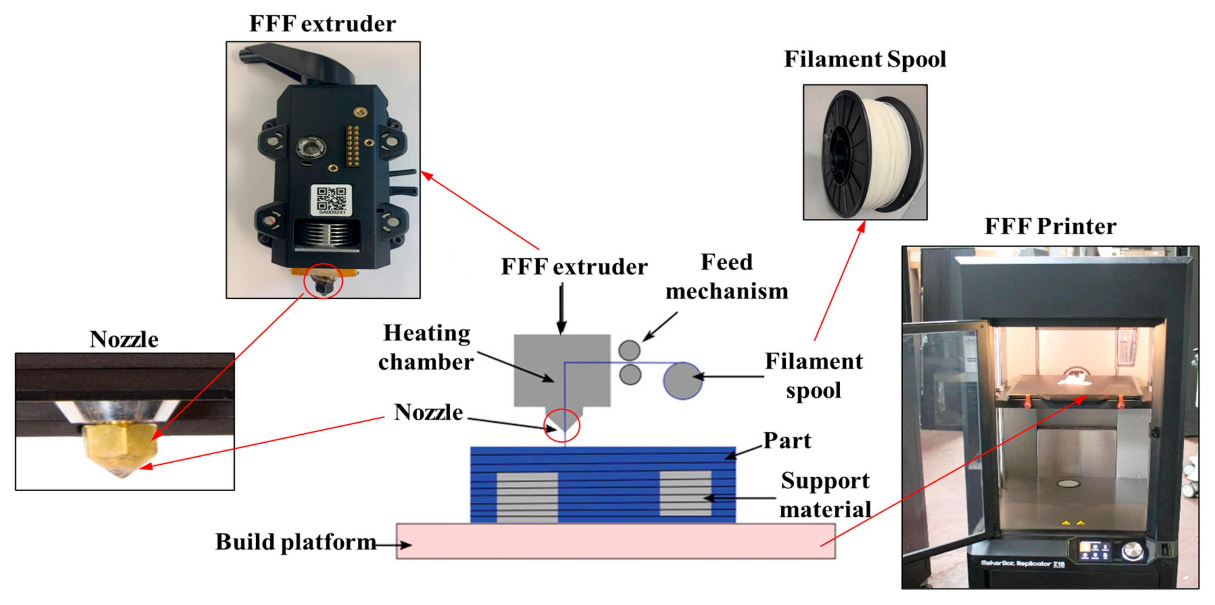
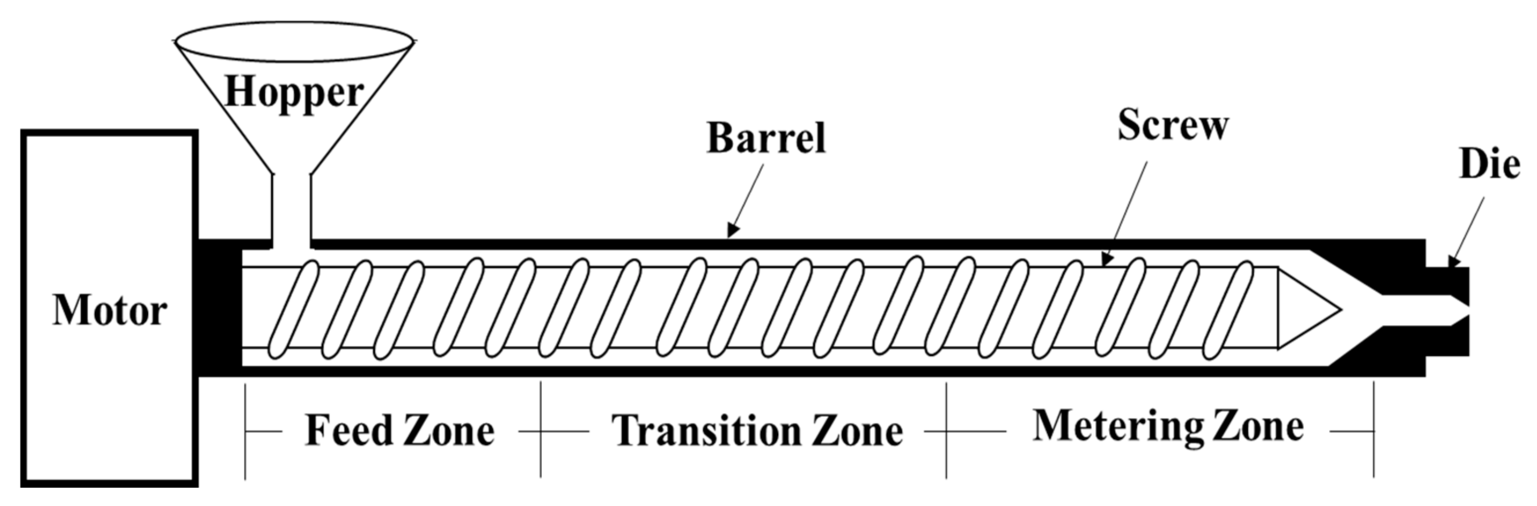
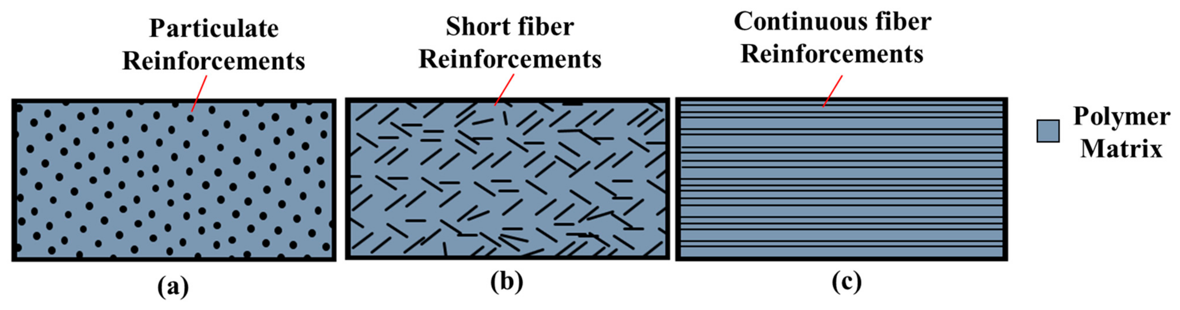
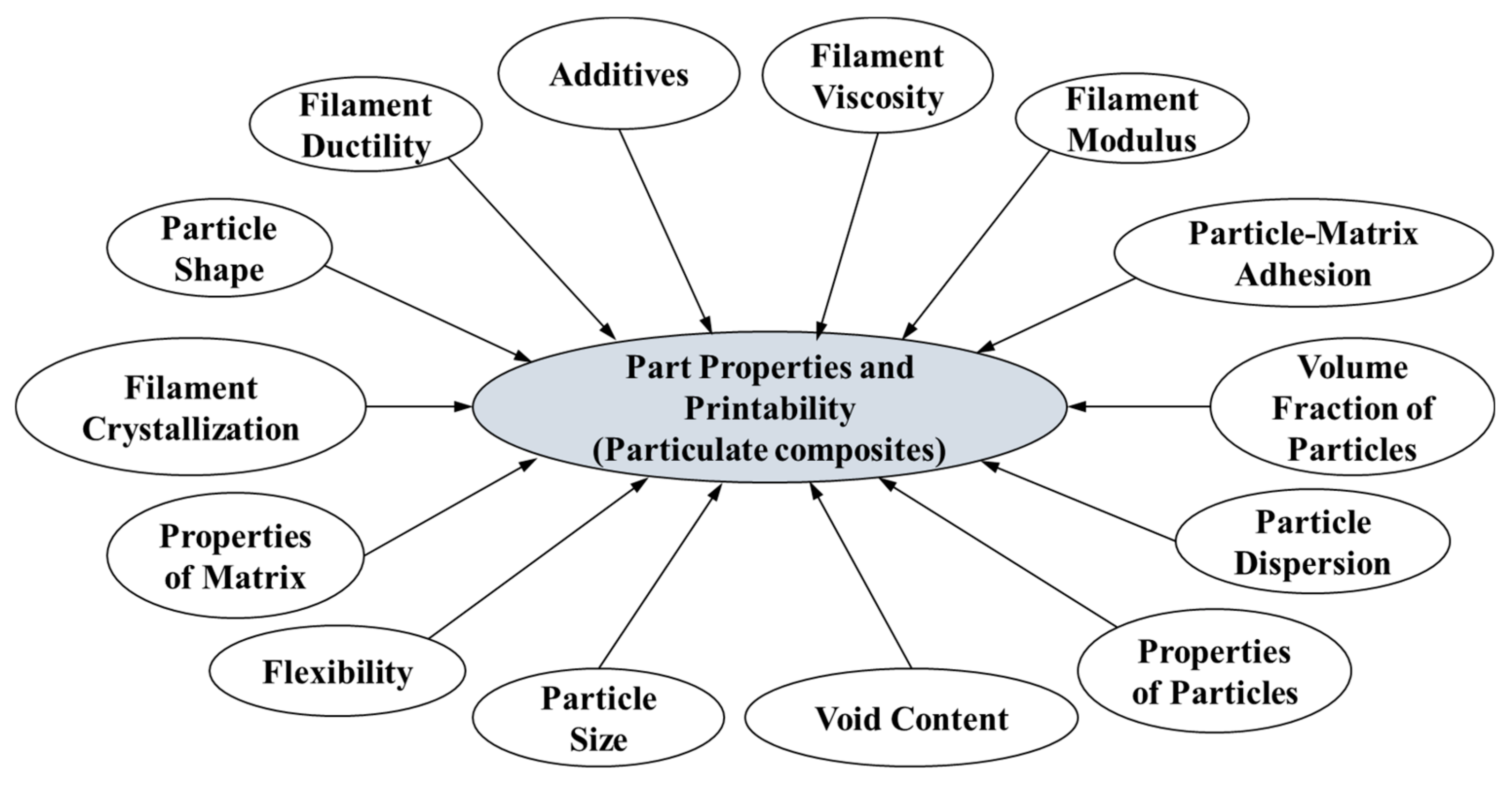
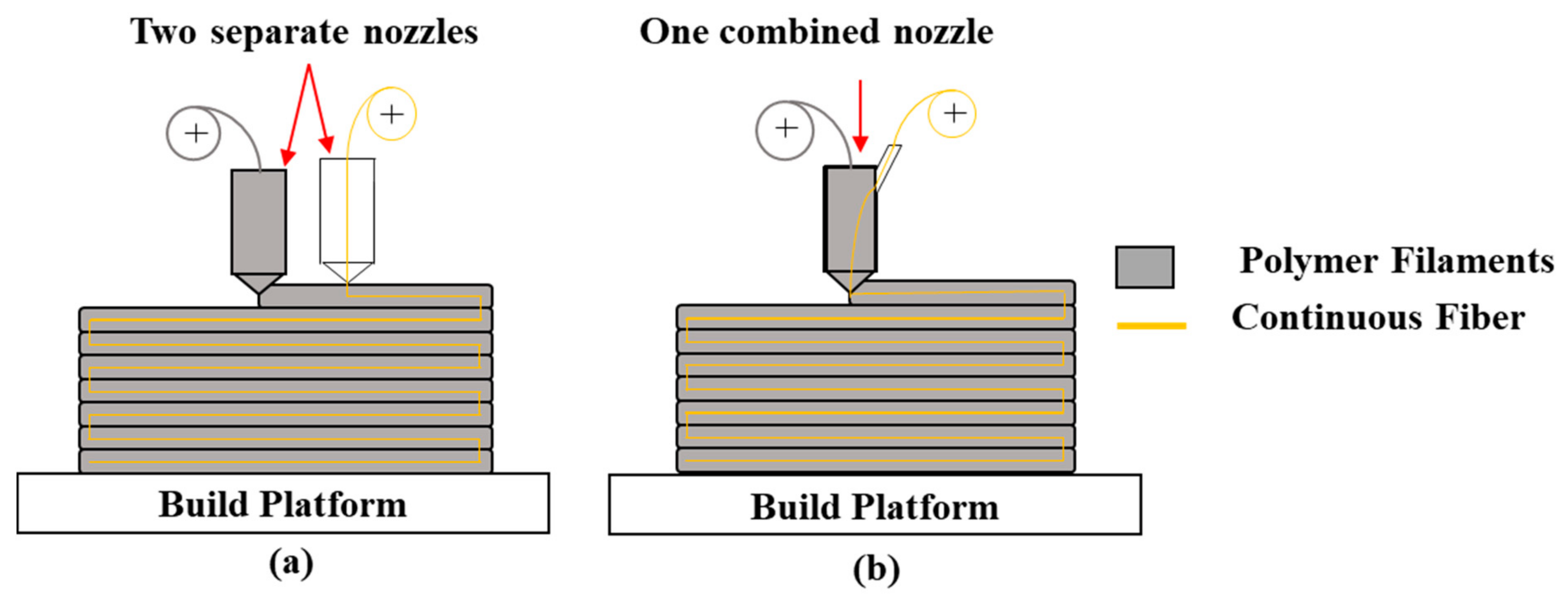
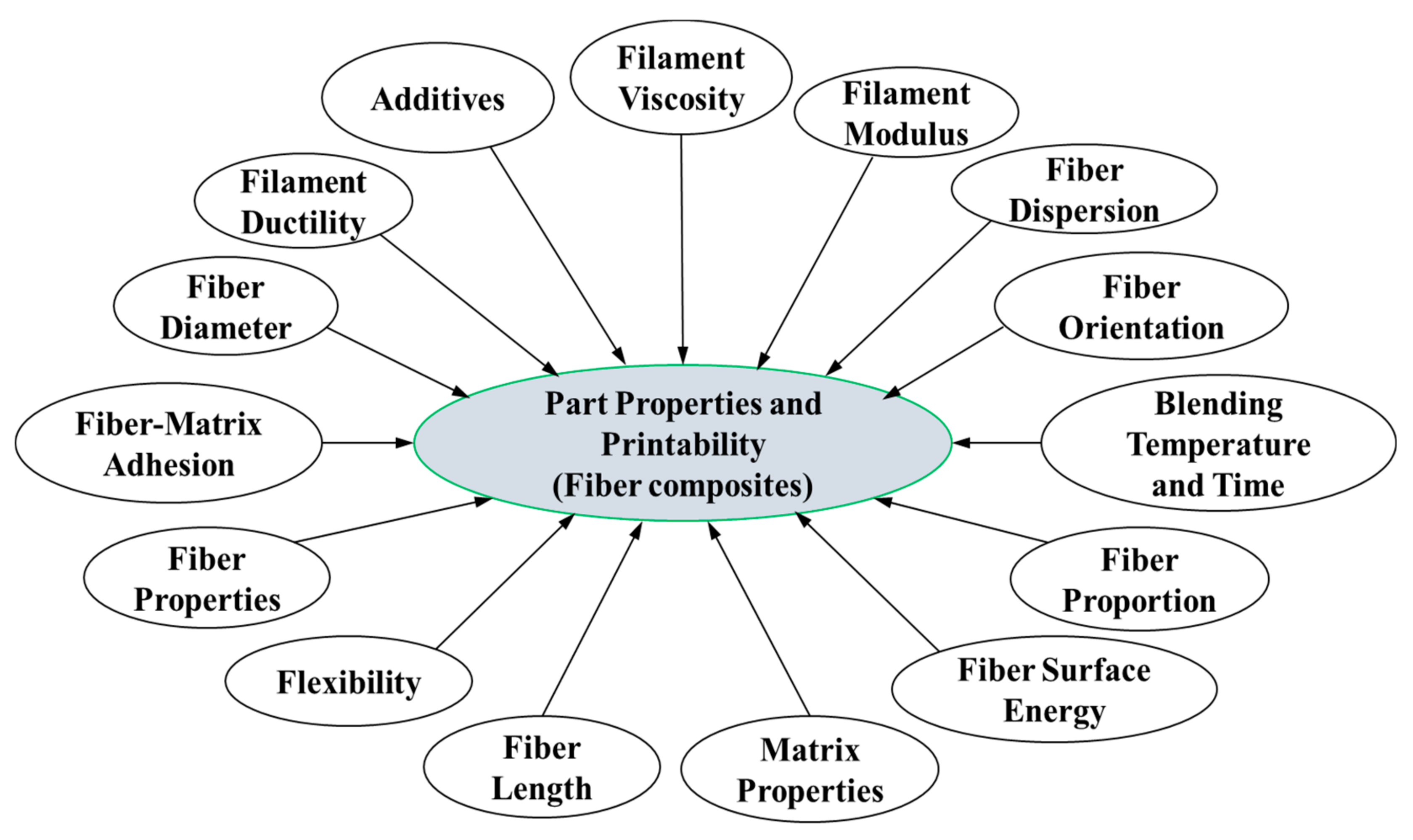
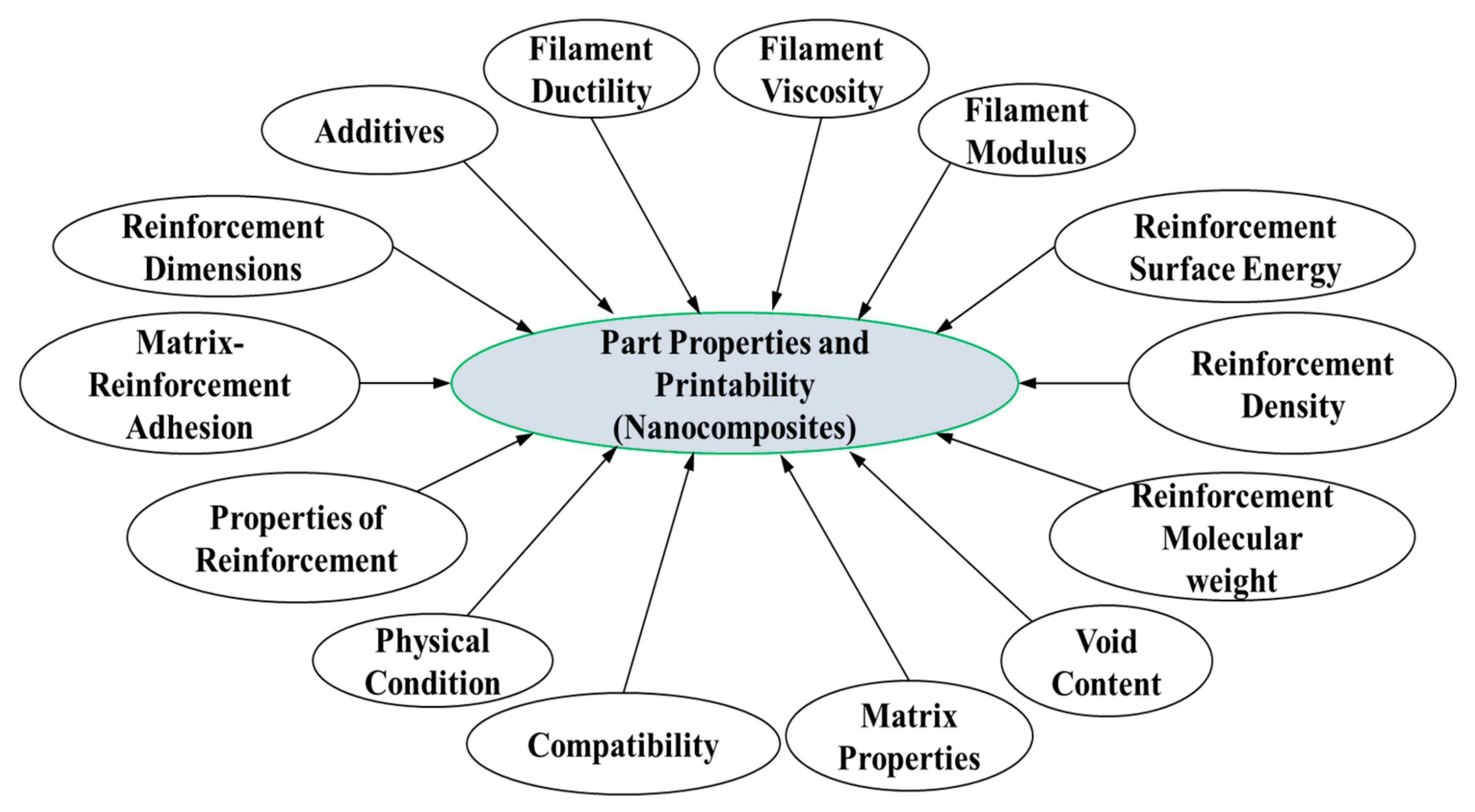
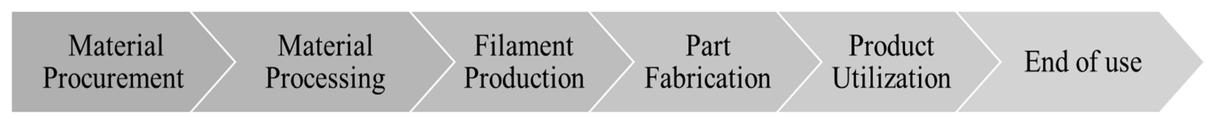
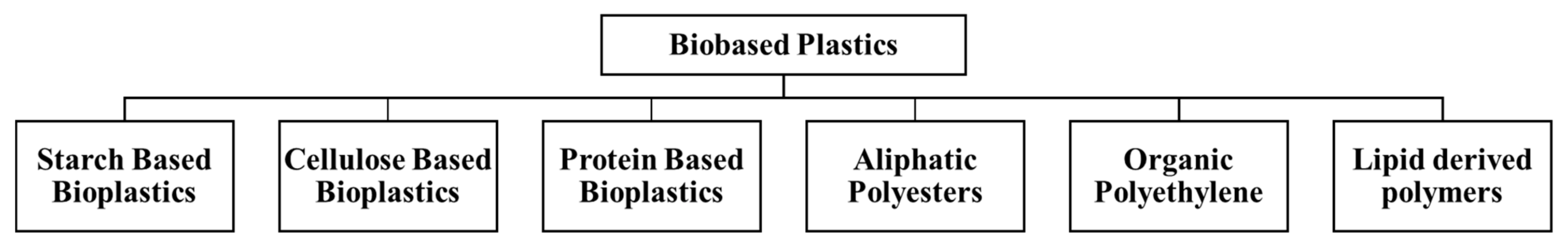
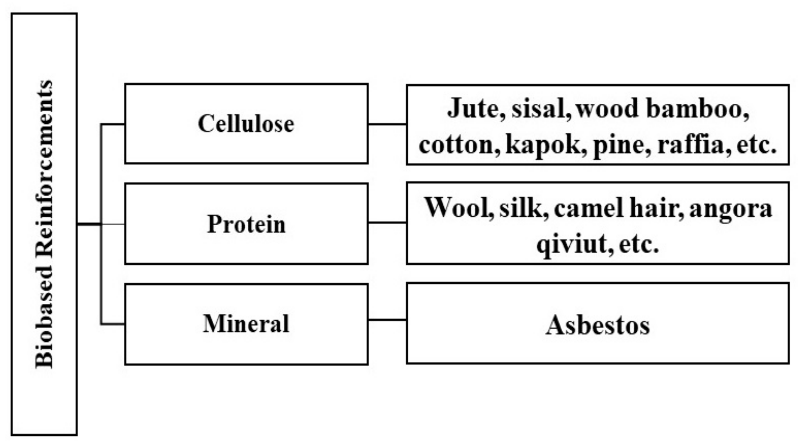
Table 1.
Fused filament fabrication (FFF) process parameters.
| Category | Parameter | Brief Description |
|---|---|---|
| Slicing parameters | Layer thickness/height | The thickness of each deposited layer in the build platform |
| Raster width | Width of deposited beads | |
| Flow rate | The volume of the filament extruded through the nozzle in per unit time | |
| Print speed | The distance an extruder goes per unit time during the print process | |
| Infill density | The percentage of the volume of the internal structure to be filled with filament material | |
| Raster orientation/angle | The direction of a raster relative to the x-axis of the respective build platform | |
| Infill pattern | Some common infill patterns are hexagonal, diamond, or linear | |
| Air gaps | In a layer, the gap between two adjacent rasters. If overlapped, this value is said to be negative | |
| Contour width | The width of the material bead used for contours | |
| Orientation | Build orientation | This parameter defines how the part is oriented on the build platform based on the Cartesian coordinate system |
| Temperature Conditions | Extrusion temperature | The temperature at which the filament is heated in a liquefier during the FFF process |
| Bed/platform temperature | The temperature of printing bed or build platform | |
| Ambient temperature | The surrounding temperature where a FFF machine is located. This temperature may impact moisture content, warping, or cooling rate |
Table 2.
A price list of pure thermoplastic filaments. ABS—acrylonitrile butadiene styrene, PLA—polylactic Acid, PC—polycarbonate, PEEK—polyether ether ketone, PEI—polyetherimide, HIPS—high impact polystyrene.
Table 2.
A price list of pure thermoplastic filaments. ABS—acrylonitrile butadiene styrene, PLA—polylactic Acid, PC—polycarbonate, PEEK—polyether ether ketone, PEI—polyetherimide, HIPS—high impact polystyrene.
| Material | ABS | PLA | PC | PEEK | PEI | Nylon | HIPS |
|---|---|---|---|---|---|---|---|
| Price per kg | $17–25 | $15–25 | $30–70 | $400–700 | $140–220 | $30–70 | $20–60 |
Table 3.
General properties of pure thermoplastic filament materials. ABS—acrylonitrile butadiene styrene, PLA—polylactic Acid, PC—polycarbonate, PEEK—polyether ether ketone, PEI—polyetherimide, HIPS—high impact polystyrene.
Table 3.
General properties of pure thermoplastic filament materials. ABS—acrylonitrile butadiene styrene, PLA—polylactic Acid, PC—polycarbonate, PEEK—polyether ether ketone, PEI—polyetherimide, HIPS—high impact polystyrene.
| Material | Source | Advantages | Disadvantages | Printing Temperature Range |
|---|---|---|---|---|
| ABS | Petroleum | Good impact resistance, toughness, inexpensive | Prone to warp, produce unpleasant gases | 210–250 °C |
| PLA | Plant starch | Biodegradable, does not warp, inexpensive | Poor mechanical properties, rough texture, brittle | 190–230 °C |
| PC | Bisphenol | Strong and flexible, good optical properties | High print temperature, absorb moisture | 260–310 °C |
| PEEK | Bisphenolate | Good rigidity and strength, light weight, heat and chemical resistance | High print temperatures, expensive, prone to warp | 360–420 °C |
| PEI | Bisphenol-A dianhydride | Good heat resistance, chemical stability, good rigidity, and strength | High print temperatures, expensive, prone to warp, difficult to print | 340–380 °C |
| Nylon | Crude oil | Good mechanical Properties, inexpensive, wear resistance, heat resistance | Prone to warp, high printing temperature | 240–270 °C |
| HIPS | Petroleum | Dissolvability, high impact resistance, biodegradable | Prone to warp, heated build platform required, emits styrene while printing | 220–250 °C |
Table 4.
Particulate Composites for filaments. ABS—acrylonitrile butadiene styrene, PLA—polylactic Acid, PC—polycarbonate, PA—polyamide, PA12—polyamide 12, polyvinyl alcohol, ZrO2—zirconium di-oxide, Al2O3—aluminum oxide, BN—boron nitride, HA—hydroxyapatite, SS—stainless steel, β-TCP—β-tricalcium phosphate.
| References | Matrix | Reinforcement Material | Percentage % of Reinforcement | FFF Machine |
|---|---|---|---|---|
| Hwang et al. [54] | ABS | Iron Copper | 10–40% 10–40% | NP-Mendel (Opencreators) |
| Masood and Song [53] | Nylon | Iron | 30% and 40% | - |
| Kalsoom et al. [55] | ABS | Diamond | 10–30% | Miicraft 3D Printer |
| Shemelya et al. [56] | PC | Tungsten | 1–5% | MakerBot Replicator |
| Mostafa et al. [57] | ABS | Iron | 10% | FDM3000 |
| Nikzad et al. [58] | ABS | Iron Copper | 10–40% 10–40% | FDM300 |
| Ryder et al. [59] | ABS | SS | 10%, 15%, and 23% | - |
| Quill et al. [60] | ABS | BN | 5–35% | Hyrel System 30 M |
| Khatri et al. [61] | ABS | Barium titanate | 10–50% | MakerBot Replicator 2X |
| Zhang et al. [62] | PLA | HA | 15% | - |
| Antoniac et al. [63] | PLA | Magnesium 150 g | 4 g 6 g | Anet A8 3D Printer |
| Singh et al. [64] | Nylon 6 | Al2O3 | 30–50% | Stratasys uPrint |
| Abdullah et al. [65] | PA 12 | ZrO2 β-TCP | 15% 15–20% | Makerbot Replicator 2X |
| Chen et al. [66] | PVA | β-TCP | 5–20% | German RepRap X350pro printer |
| Corcione et al. [67] | PLA | Micron-sized HA | ≤50% | 3DPRN LAB 3D printer |
| Wei et al. [68] | ABS | Graphene oxide | 0.4–7.4% | HOF1-X1 |
| PLA | Graphene oxide | 0.8% | HOF1-X1 | |
| Rahim et al. [69] | PA | HA ZrO2 | 5% 15% | Makerbot Replicator 2X |
| Spoerk et al. [70] | Polypropylene | Glass | 30% | Duplicator i3 v2 |
| Nabipour et al. [71] | Polyethylene | Copper | 25%, 50%, and 75% | - |
| Nabipour and Akhoundi [72] | ABS | Copper | 25% | Quantum FDM 3D printer type 2020 |
Table 5.
Short fiber composites for filaments. ABS—acrylonitrile butadiene styrene, PLA—polylactic Acid, PC—polycarbonate.
Table 5.
Short fiber composites for filaments. ABS—acrylonitrile butadiene styrene, PLA—polylactic Acid, PC—polycarbonate.
| References | Matrix | Reinforcement Fiber Materials | Percentage % of Reinforcement | FFF Machine |
|---|---|---|---|---|
| Ferreira et al. [78] | PLA | Carbon | 15% | BQ Prusa i3 Hephestos |
| Kamaal et al. [79] | PLA | Carbon | 5.5% | Ypanx Falcon 3D printer |
| Ning et al. [80] | ABS | Carbon | 3–15% | Leapfrog 3D Printers |
| Zhang et al. [81] | ABS | Carbon | 15% | QIDI Tech dual-nozzle 3D printer |
| Tekinalp et al. [82] | ABC | Carbon | 10–40% | Solidoodle 3 |
| Sodeifian et al. [83] | Polypropylene | Glass | 30% | SIZAN 3D printer |
| Gupta et al. [84] | PC | Carbon | 3–7.5% | Ultimaker 3 |
| Mohammadizadeh et al. [85] | Nylon | Carbon | 8 wt.% | ULTIMAKER S5 |
Table 6.
Continuous fiber composites for filaments. ABS—acrylonitrile butadiene styrene, PLA—polylactic Acid, PA—polyamide.
Table 6.
Continuous fiber composites for filaments. ABS—acrylonitrile butadiene styrene, PLA—polylactic Acid, PA—polyamide.
| References | Matrix | Continuous Fibers | FFF Machine |
|---|---|---|---|
| Li et al. [89] | PLA | Carbon | - |
| Tian et al. [90] | PLA | Carbon | - |
| Melenka et al. [91] | Nylon | Kevlar | MarkOne 3D printer |
| Hart et al. [92] | Nylon | Carbon | Markforged Mark 2 |
| Van Der Klift et al. [93] | Nylon | Carbon | Mark One 3D Printer |
| González-Estrada et al. [94] | Nylon | Glass/carbon | Mark Two 3D printer |
| Akhoundi et al. [95] | PLA | Glass | - |
| Bettini et al. [96] | PLA | aramid | Blue Tek Strato |
| Mori et al. [97] | ABS | Carbon | - |
| Araya-Calvo et al. [98] | PA | Carbon | Mark Two 3D printer |
| Mohammadizadeh et al. [85] | Nylon | Carbon | Markforged Mark Two |
| Brooks and Molony [99] | PLA | Carbon, Kevlar, basalt, and 316 stainless steel wire | MakerGear M2 |
| ABS | Da Vinci 1.0 A |
Table 7.
Nanocomposites for filaments. ABS—acrylonitrile butadiene styrene, PLA—polylactic Acid, PA12—polyamide 12, PEEK—polyether ether ketone, PCL—polycaprolactone, TPU—thermoplastic polyurethane, HA—hydroxyapatite, MWCNT—multiwall carbon nanotubes, MMT—nano montmorillonite.
Table 7.
Nanocomposites for filaments. ABS—acrylonitrile butadiene styrene, PLA—polylactic Acid, PA12—polyamide 12, PEEK—polyether ether ketone, PCL—polycaprolactone, TPU—thermoplastic polyurethane, HA—hydroxyapatite, MWCNT—multiwall carbon nanotubes, MMT—nano montmorillonite.
| References | Matrix | Nanocomposite Fibers Material | Percent % of Reinforcement | FFF Machine |
|---|---|---|---|---|
| Weng et al. [106] | ABS | Organic modified montmorillonite | 1%, 3%, and 5% | Creator 3D Printer |
| Dul et al. [107] | ABS | Graphene nanoplatelet | 2%, 4%, and 8% | Sharebot NextGeneration desktop 3D printer |
| Bustillos et al. [108] | PLA | Graphene | - | MakerBot Replicator 2 |
| Gonçalves et al. [109] | PEEK | Carbon nanotubes and graphite nanoplates | - | - |
| Zhu et al. [110] | PA12 | Graphite nanoplates | 6% | |
| Christ et al. [111] | TPU | MWCNT | 3% | Makerbot Replicator 2 |
| Prashantha and Roger [112] | PLA | Graphene nanoplates | 10% | - |
| Haq et al. [113] | PCL | MMT MMT/HA | 2–4% 2–4%/10% | - |
| Gardner et al. [114] | Ultem | Carbon nanotube | - | - |
Publisher’s Note: MDPI stays neutral with regard to jurisdictional claims in published maps and institutional affiliations. |
© 2021 by the authors. Licensee MDPI, Basel, Switzerland. This article is an open access article distributed under the terms and conditions of the Creative Commons Attribution (CC BY) license (https://creativecommons.org/licenses/by/4.0/).
Share and Cite
MDPI and ACS Style
Dey, A.; Roan Eagle, I.N.; Yodo, N. A Review on Filament Materials for Fused Filament Fabrication. J. Manuf. Mater. Process. 2021, 5, 69. https://0-doi-org.brum.beds.ac.uk/10.3390/jmmp5030069
AMA Style
Dey A, Roan Eagle IN, Yodo N. A Review on Filament Materials for Fused Filament Fabrication. Journal of Manufacturing and Materials Processing. 2021; 5(3):69. https://0-doi-org.brum.beds.ac.uk/10.3390/jmmp5030069
Chicago/Turabian StyleDey, Arup, Isnala Nanjin Roan Eagle, and Nita Yodo. 2021. "A Review on Filament Materials for Fused Filament Fabrication" Journal of Manufacturing and Materials Processing 5, no. 3: 69. https://0-doi-org.brum.beds.ac.uk/10.3390/jmmp5030069