1. Introduction
The chipping of the cutting edge at the end of the tool manufacturing process chain is one of the decisive factors for the application behavior of the tools. The manufacturing of cutting tools, e.g., from carbide, is usually carried out with the process steps of sintering or pressing of the blank, grinding, edge preparation, and coating with pre- and post-treatment [
1]. The carbide blanks produced in the sintering or pressing process exhibit dimensional and shape deviations due to the process-related shrinkage.
Furthermore, their surfaces often do not meet the requirements of cutting tools [
1]. Grinding is therefore used after the sintering or pressing process to generate the final macro-geometric shape of the tools, and to produce surfaces that meet the requirements. In the case of cemented carbide tools, grinding is usually performed with diamond grinding wheels due to the high hardness, high wear resistance, and low ductility [
2]. Furthermore, mainly resin bonded grinding wheels are used, but ceramic and hybrid bonded (metallic phases combined with portions of other bond systems) grinding wheels may also be utilized [
3,
4]. By selecting the input variables during grinding, the chip thickness of the individual abrasive grain involved in the process can be changed. This is important for the process design and the resulting properties of the ground tool [
3]. Friemuth [
1] and Maldaner [
2] showed that both the average single grain chip thickness h
cu and the diamond grain size d
G lead to an increase in the maximum roughness depth Rmax during transverse face grinding. Moreover, an influence of the bond of the abrasive on the resulting chipping could be demonstrated. Denkena et al. [
5] proved with their investigations that the grinding direction has a significant influence on the size and shape of the cutting edge chipping, characterized by Rmax and Rz.
In addition to the process conditions, which are determined by the input variables of the grinding process, the grinding tool wear is of particular interest for the resulting cutting edge. The occurrence of wear is significantly influenced by the input variables, such as grinding wheel bonding, material, and cooling lubricant supply [
6].
After grinding, the cutting edges of the tools often show micro defects or burrs [
7]. These destabilize the cutting edge, and result in a reduced tool life, workpiece quality, and process reliability [
7]. Thus, tool costs and production times increase. This is due to the increased probability of sporadic cutting edge failure caused by locally occurring stress peaks at the cutting edge. Therefore, to increase the performance of the tools, they are usually subjected to cutting edge preparation.
The methods of wet and dry blasting [
8,
9,
10], brushing [
11,
12], and drag finishing [
13] are predominantly used for the targeted preparation of the cutting edge rounding [
14]. The reduction in cutting edge chipping has also been demonstrated using magnetic finishing [
7,
13,
15]. Furthermore, a targeted and reproducible adjustment of cutting edge rounding requires low cutting edge chipping [
16]. Another effect of cutting edge preparation is the removal of droplets from coated tools [
17].
The increasing use of high-speed cutting (HSC) and high-performance cutting (HPC) is associated with rising demands on tool wear resistance. In order to meet these high requirements, new coating technologies and a wider range of coating materials are needed. Innovative Physical Vapour Deposition (PVD) processes enable the synthesis of high-performance nitride, carbide, or oxide coatings with excellent physical and mechanical properties, as well as high chemical and thermal resistance. For example, TiAlN, CrTiAlN, and CrTiAlSiN coatings deposited on cemented carbide using pulsed magnetron sputtering technology show significantly improved application behavior compared to commercial TiAlN coatings when turning high alloy steels [
18]. The pretreatment of the substrates plays an equally important role in the further development of the tools [
19,
20] as subsequent processes, such as laser machining, temperature treatment, or micro-blasting [
19,
20,
21]. Regarding the cutting edge chipping, a reducing effect by coating is shown. This accumulates into the cavities of the cutting edges, and thus leads to an improvement of the edge quality [
22].
Tactile and optical measuring methods are predominantly used to measure the cutting edge chipping. These differ in terms of reproducibility of the measurement results, measurement duration, position of the measured object, and achievable resolution [
23]. A significant advantage of non-contact micro-optical methods is the three-dimensional acquisition of the cutting edge geometry by simultaneous evaluation of several profile sections along the cutting edge. Compared to tactile measuring methods, however, there are disadvantages with regard to the reproducibility of the measuring results [
11].
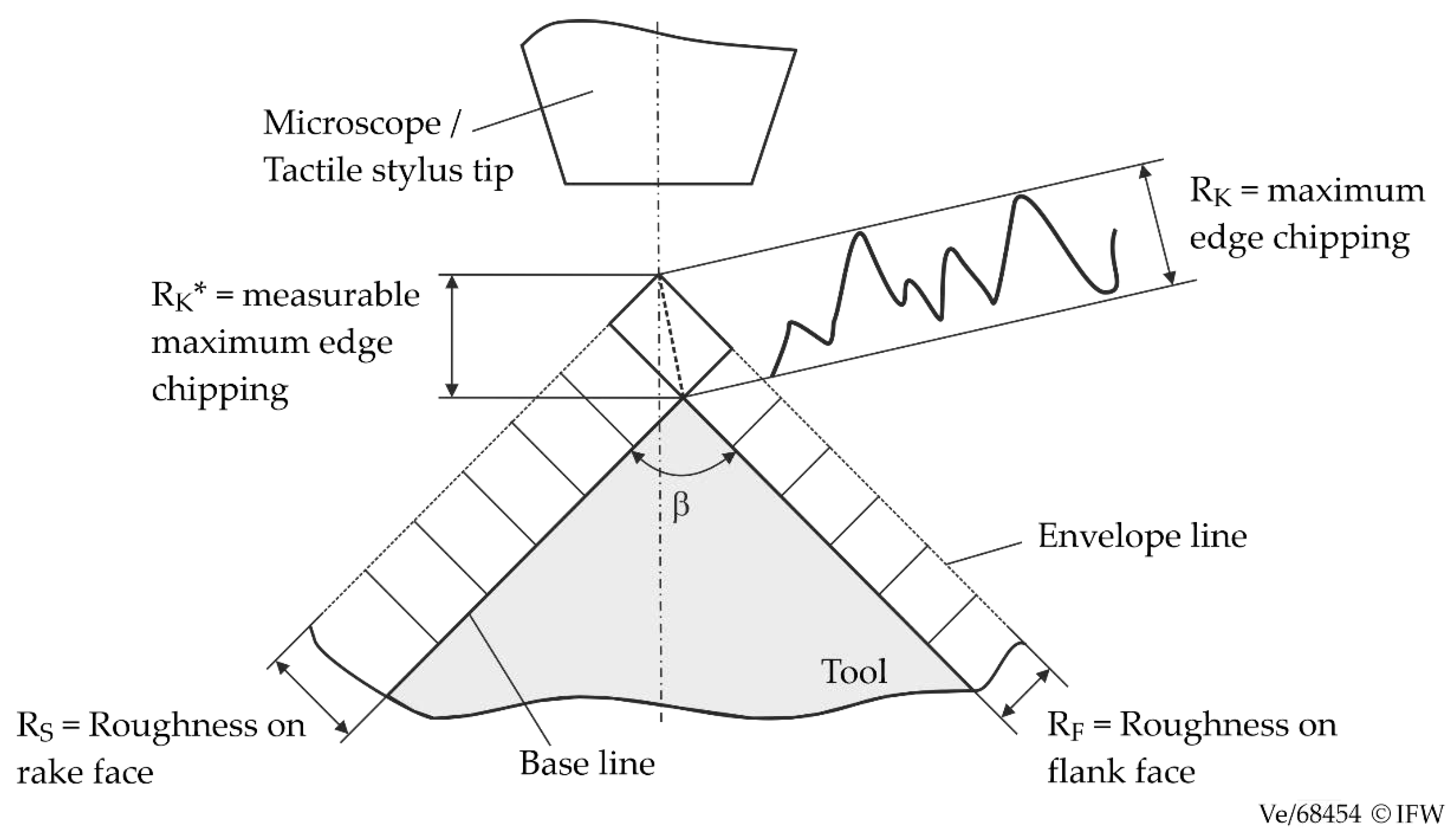
In order to characterize the cutting edge chipping, Heiß [
24] defined the cutting edge as the connecting line between the rake face and the flank face assuming ideally sharp tools. For rounded tools, the area where effective rake and clearance angles,
γeff and
αeff, differ from the nominal angles,
γ and
α, is considered as the cutting edge [
17].
Figure 1 shows the schematic representation of edge sharpness according to Heiß, which is related to an ideally sharp cutting edge [
24]. After edge preparation, the original definition of cutting edge chipping according to [
24] is no longer applicable, as there is no longer a defined connecting line between the rake face and the flank face, so that line-based parameters can only be used to a limited extent to describe the topography of the cutting edge. Therefore, in the following, cutting edge chipping is understood as a term for the initial deviation between the real and ideal cutting edge microtopography after tool manufacturing. This means there are no micro-breakouts on the cutting edges of the tools after a short period of use.
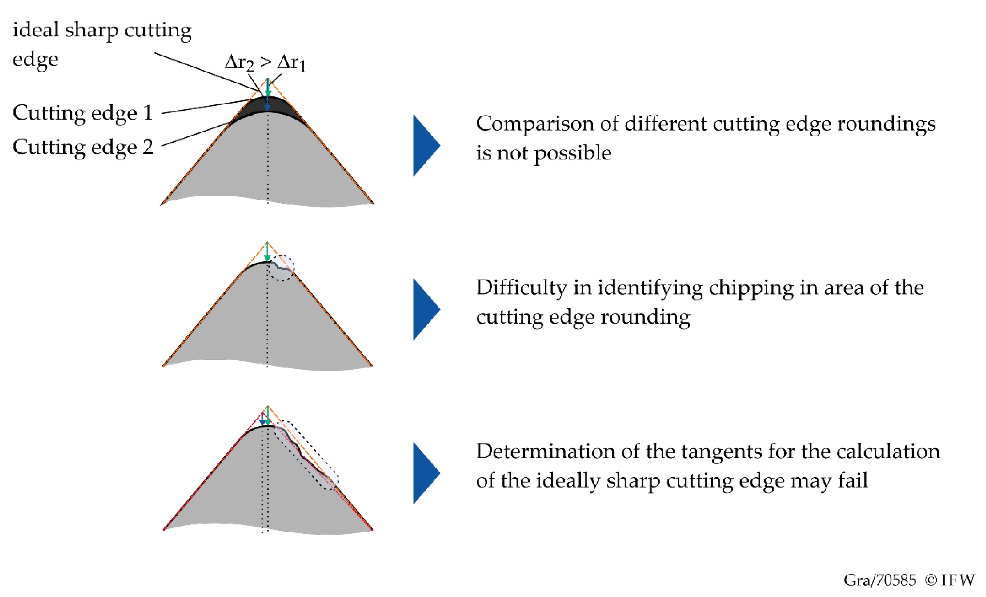
A conventional and industrially frequently used method for characterizing the chipping is the so-called Δ
r-method. For this purpose, a height profile of the cutting edge is generated with optical measuring methods, such as fringe light projection. The value Δ
r describes the distance from the highest point of the cutting edge to the point of intersection of the tangents of the rake face and flank face. By averaging the chipping Δ
r of all profile sections, the average edge chipping Δ
rmid is used to characterize the chipping. However, a quantitative comparison of the chipping for cutting edge roundings of different sizes is not possible, as the value Δ
r depends directly on the rounding size and the macro-geometry (
Figure 2). Therefore, the aim of this work is to create a new method for the determination of cutting edge chipping.
In scientific works, the cutting edge chipping is often described by the roughness parameters Ra, Rz, Rp, Rv, and Rmax, as well as the parameters of the material removal curve Rpk, Rk, and Rvk [
1,
2,
8,
22]. For roughness profiles, Rz represents the maximum roughness. The average smoothing depth Rp is the distance from the center line to the highest peak of a single measurement section. Rv describes the distance from the center line to the lowest peak of an individual measurement. However, the calculation of the core roughness depth Rk is influenced by large breakouts and the grinding direction. The informative value of the line profile is limited due to the selected measuring position and measuring direction. Thus, the actual suitability of these parameters is unclear.
The current state of the art shows that the influence of the process parameters on the chipping for individual process steps along the process chain in the manufacture of cutting tools is already sufficiently well known. However, the influence of the initial chipping before the individual steps of the process chain on the resulting chipping after the individual process steps is not known. In addition, the application behavior of the tools as a function of the cutting edge chipping has not been sufficiently researched. In particular, there is insufficient knowledge regarding the interactions between the cutting edge chipping and the cutting material properties, process parameters, as well as the micro- and macro-geometry on the tool application behavior. Despite the numerous scientific efforts in this field, there are currently no characterization parameters that describe the wear-determining characteristics of the cutting edge microtopography with sufficient accuracy. Therefore, this publication investigates the influence of the end mill manufacturing process chain on cutting edge chipping, and derives a parameter describing the influence of this on the wear behavior.
2. Influence of Tool Manufacturing Process on Cutting Edge Chipping
In the first part of the investigations, grinding, cutting edge preparation, and the coating process, as well as the coating post-treatment were investigated as essential process steps of the tool manufacture, with regard to their effect on the chipping and the microgeometry of the cutting edge. The milling tools were analyzed in each case before and after the corresponding process steps.
The optical form and roughness measuring device Alicona Infinite Focus G5 was applied to measure the cutting edge and the cutting edge roughness. The microscope uses the measurement principle of focus variation, which is particularly suitable for the optical measurement of complex three-dimensional tool geometries with sufficient resolution. Due to the higher geometric resolution, additional scanning electron microscope (SEM) analyses of the cutting edges were carried out for selected tools with a SEM Zeiss EVO 60.
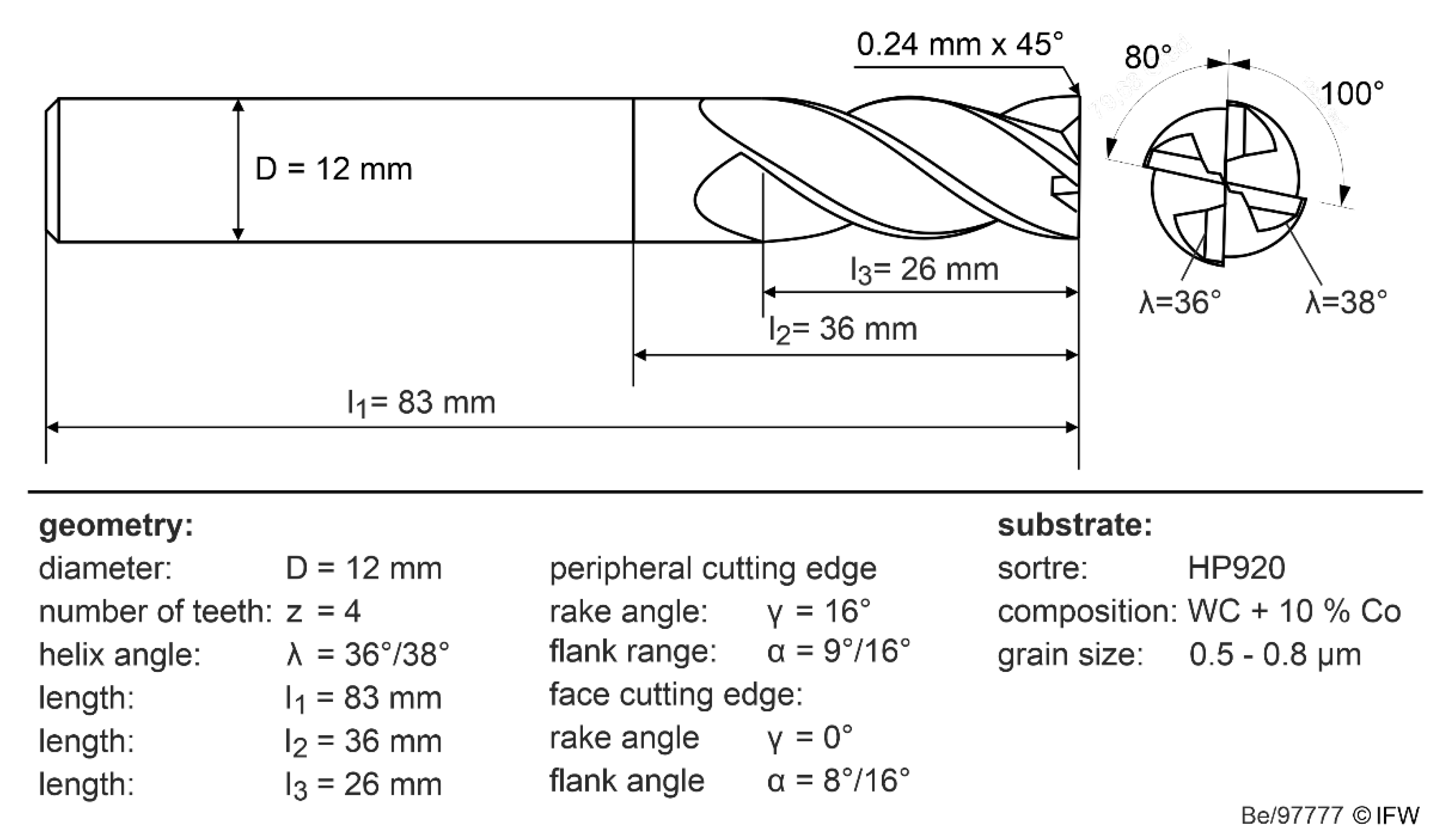
In the first step, the influence of the process parameters during grinding of end mills was investigated. For this purpose, round-ground cemented carbide blanks of the company Mapal Dr. Kress KG of the type HP920, with a cobalt content of 9% and a diameter of D = 12 mm, were used. A 5-axis HELITRONIC VISION 400 L tool grinding machine from Walter was used for the grinding tests. The resulting tool geometry after grinding is shown in
Figure 3 below.
Diamond grinding wheels with a grain concentration of C100 (4.4 carats/cm³) and grain sizes of D30 and D76 (FEPA standard) were used for the investigations. Resin bonded grinding wheels were used for flute grinding, and hybrid bonded grinding wheels were applied for grinding the clearance angle of the end teeth and peripheral teeth. To investigate the influence of process parameters during grinding, the feed rate v
f and cutting speed v
c were varied in three steps each, and the abrasive grain size was varied in two steps based on a full factorial experimental design (
Table 1).
In addition, for a selected process parameter combination (D76, v
c = 15 m/s, v
f(Fluting) = 30 mm/min, v
f(Clearance angle) = 50 mm/min), the influence of grinding kinematics was investigated for flute and circumferential grinding. As the cutting edge chipping is generally subject to a stochastic distribution along the cutting edge, a total of four replicate tests were performed to quantify the microtopography.
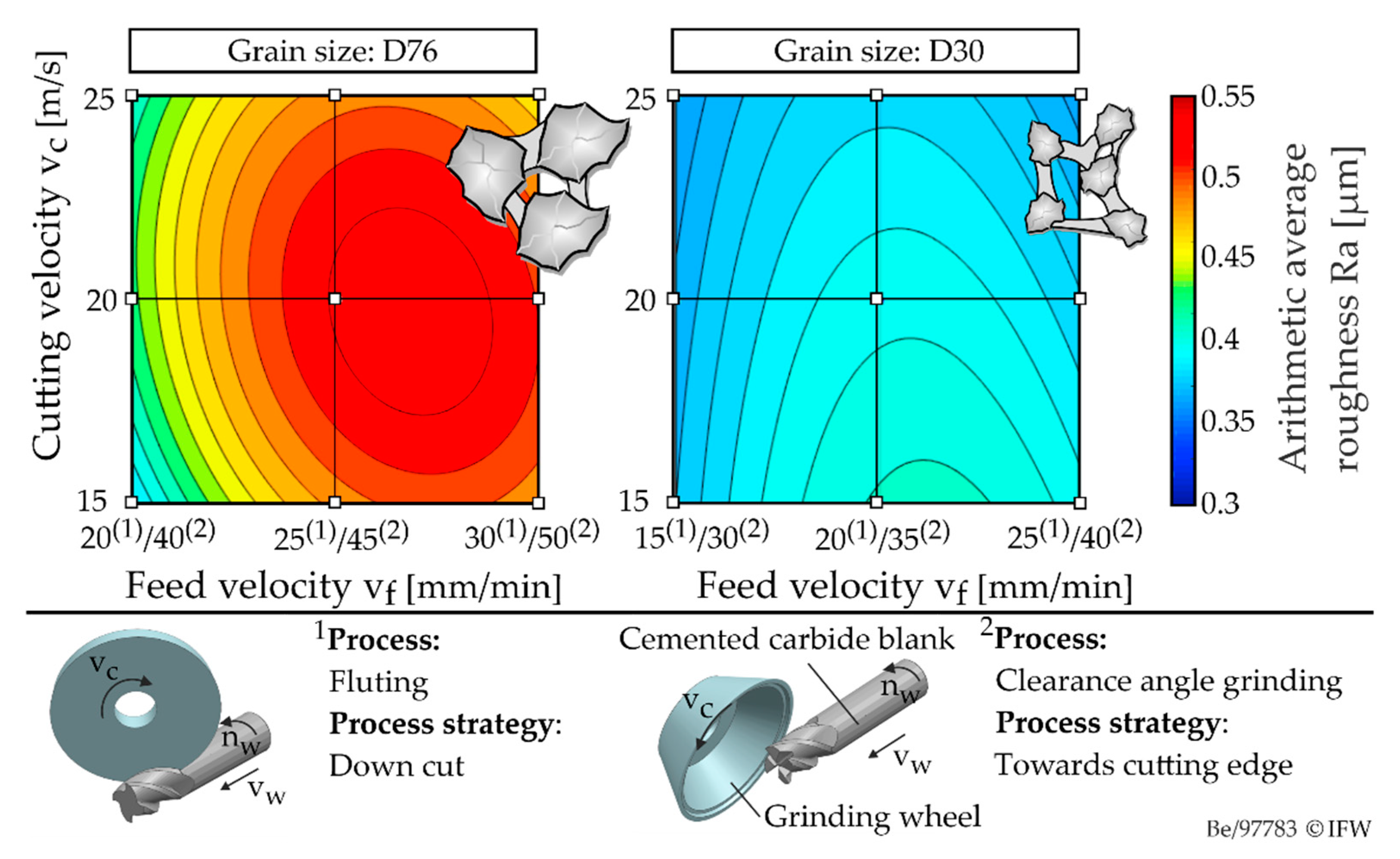
Figure 4 shows the influences of cutting speed and feed rate during grinding, as well as their interaction under variation of the grain size on two levels (D30 and D76) exemplarily in relation to the arithmetic mean roughness on the cutting edge Ra. The contour plots shown were determined using local linear regression (LOWESS), and have a root-mean-square deviation (RSME) of 0.01 µm.
One of the main factors influencing the quality of the cutting edge is the grain size of the abrasive. An increase in grain size from D30 to D76 leads to a significant increase in the average roughness value by 25%. In addition, it can be seen that the average roughness Ra increases slightly with increasing feed rate. This can be attributed to the thermomechanical load. The values of the roughness parameters increase with increasing mechanical load, characterized by the average single grain uncut chip thickness h
cu. The single grain uncut chip thickness can be assumed to be proportional to the ratio of the feed rate to the cutting speed. This can be observed up to a critical value. From this value on, the size of the average single grain chip thickness favors a brittle material removal. As a result, the values of the roughness parameters decrease. Furthermore, if the cutting speed is reduced and the feed rate is increased, a reduction in the thermal load and, consequently, a lower thermal softening of the cemented carbide can be expected. The reduction in the local thermal stress seems to compensate the effect of the increasing single grain uncut chip thickness. In contrast, the decrease in roughness parameters at high cutting speeds is due to the higher ductility of the cemented carbide as a result of thermal softening. The process strategy with regard to the kinematics of the grinding wheels also has a significant influence on the roughness parameters considered (
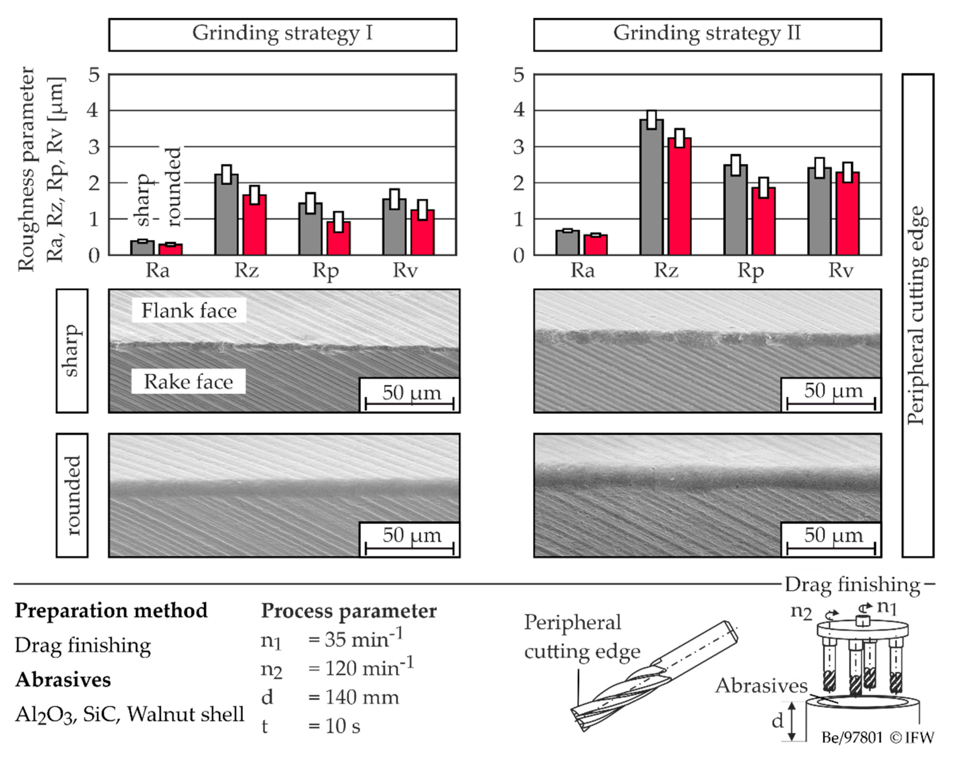
Figure 5). In this context, the orientation of the cutting vector during grinding of the circumferential flank face shows a significant influence on the cutting edge quality. Thus, a trajectory of the abrasive grain in the direction of the cutting edges favors the cutting edge quality [
23]. The material near the cutting edge undergoes a supporting effect, and is subjected to compressive stresses that counteract crack initiation. In contrast, a reversed trajectory, starting from the flank face in the direction of the cutting edge, causes a reduction in surface quality. The tensile stresses induced during grain exit promote the formation of stress cracks, which can be attributed to the low tensile strength of cemented carbide. The influence of flank face grinding outweighs the influence of flute grinding. Thus, only a slight increase in edge roughness was observed when changing from down-cut grinding to up-cut grinding. In the following, the combination of climb grinding during groove machining and a trajectory in the direction of the edge during circumferential machining will be referred to as strategy 1, and the reverse case as strategy 2.
In the second step, the influence of the initial condition of the tools after grinding, as well as the influence of the cutting edge preparation on the chipping, were investigated. The rounding of the cutting edges was performed by drag finishing at Surcoatec Deutschland GmbH. On the basis of the previous findings, tools with different degrees of sharpness were ground, then prepared by varying the process duration (30 s or 60 s) during drag finishing. Additionally, milling tools were also rounded using a process developed at IFW. The preparation was carried out with flexible polishing tools on a 5-axis machining center of the type Ultrasonic 10 from DMG Sauer.
The results show that edge preparation by drag finishing affects the edge roughness. The values of the roughness parameters are reduced by up to 25% (
Figure 5).
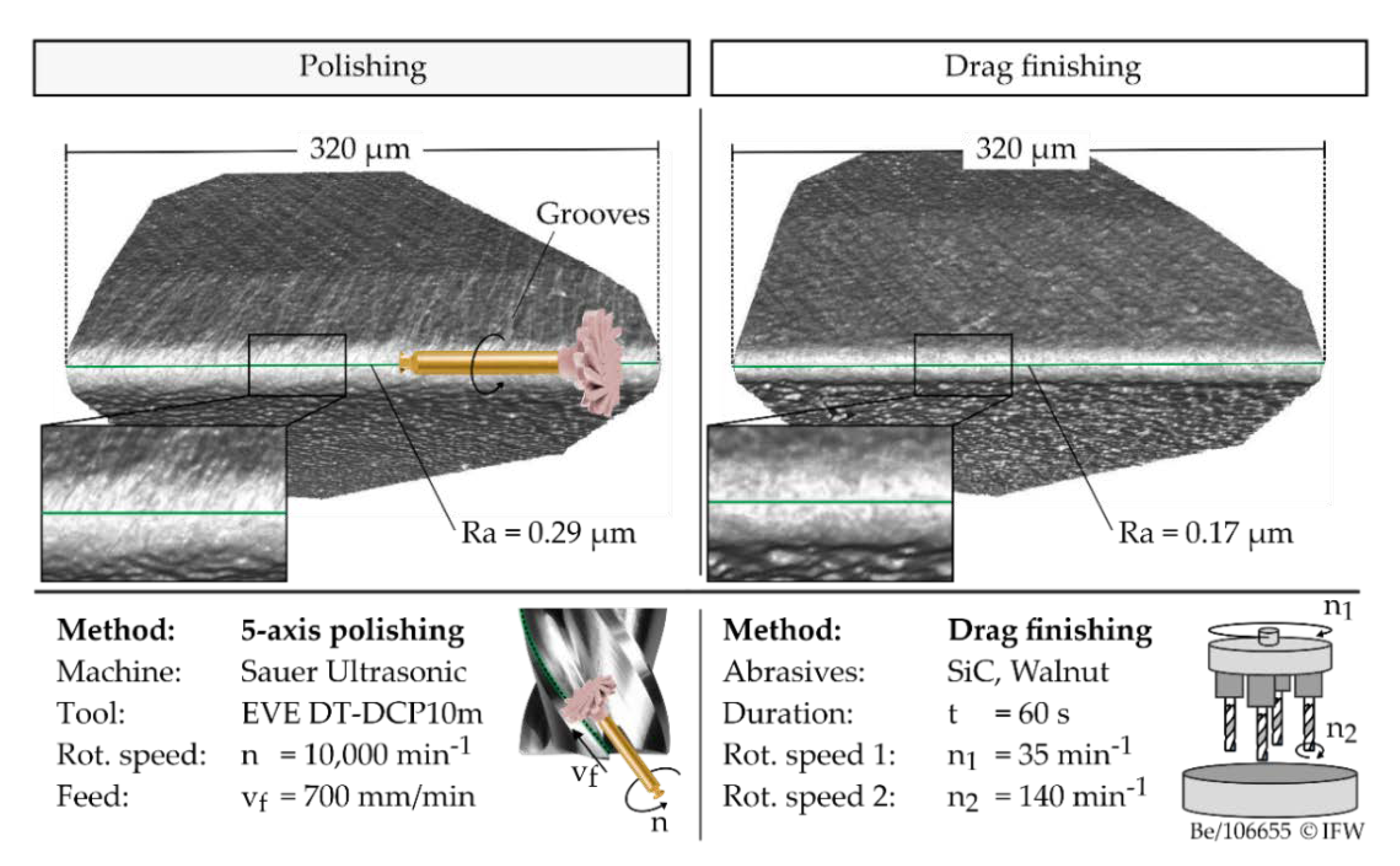
The edge roughness is reduced independently of the initial roughness. With regard to the microgeometry of the cutting edge, no significant differences can be observed between the investigated roughness levels after edge preparation. In contrast, the roughness along the cutting edge is influenced by the condition of the cutting edge before drag finishing. In this respect, it could be shown that a higher initial roughness before drag finishing results in a higher roughness after drag finishing for the selected process parameters, and that differences in the roughness parameters continue to exist after edge preparation. Applying the polishing process developed at IFW, the edge roughness can be reduced by 17–30% with respect to the arithmetic average roughness value at comparable initial roughness, depending on the process parameters. Thus, both processes show the potential to increase edge quality. However, the polished tools show periodic grooves and a higher roughness along the cutting edge, which can be traced back to the process kinematics, shown in
Figure 6.
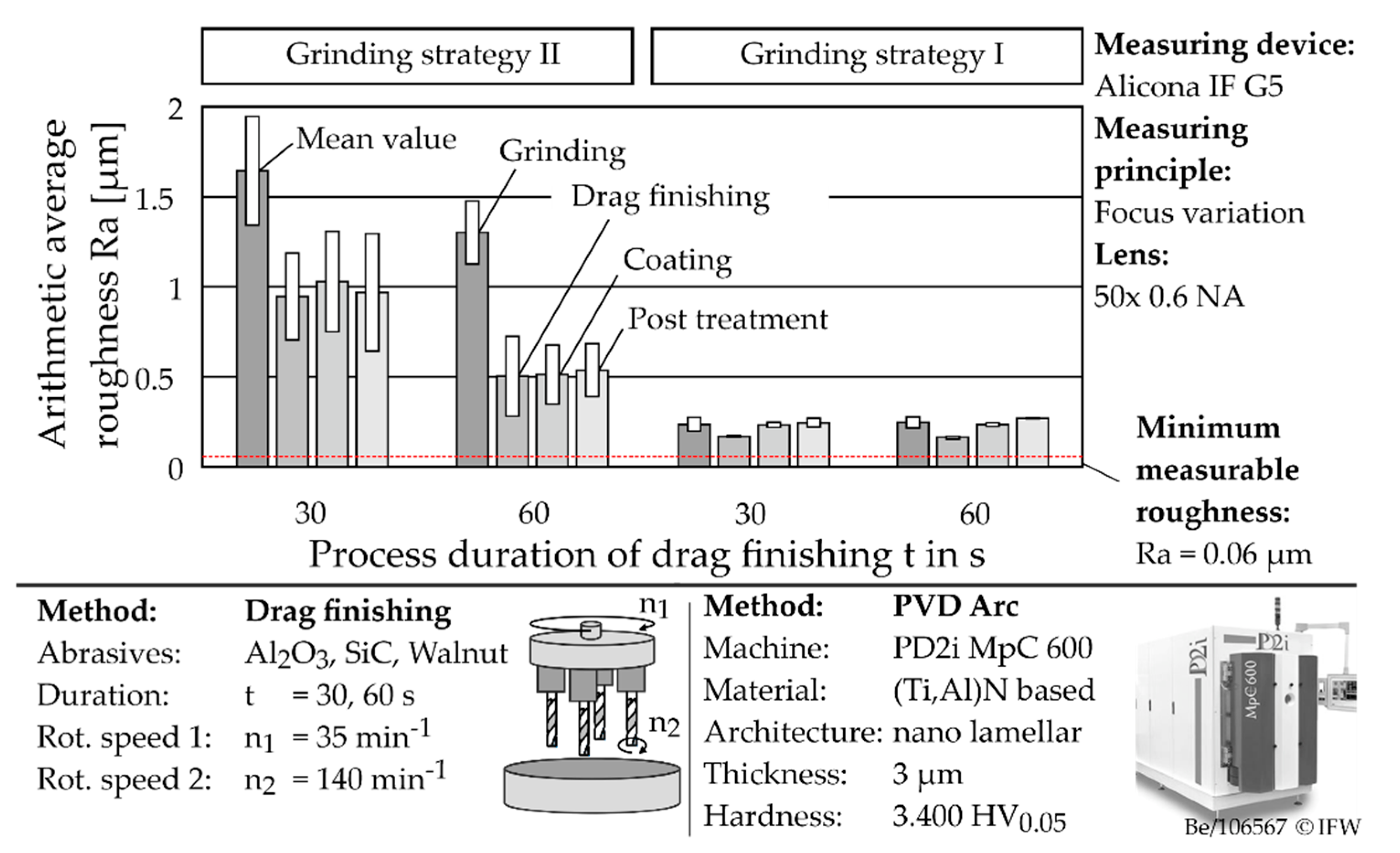
Finally, the influence of the coating process and the coating post-treatment were investigated. For this purpose, a commercially available nanolaminar (Ti,Al)N coating was synthesized using the PVD-Arc process. The coating post-treatment was again performed by drag finishing. The process parameters for coating and post-treatment were kept constant. In the following, the interactions within the whole process chain are discussed. It has already been shown that a different initial roughness due to grinding cannot be equalized with the selected process parameters, and that differences in the roughness parameters continue to exist after edge preparation. This effect was also observed when the process duration of drag finishing was increased from t = 10 s to t = 30 s and t = 60 s (
Figure 7) with subsequent coating and coating post-treatment. In addition, the initial cutting edge roughness has a significant effect on the cutting edge rounding. The resulting cutting edge rounding was 25 ± 3 µm for strategy 2 (high roughness) and 18 ± 3 µm for strategy 1 (low roughness). In contrast, the process duration during drag finishing showed only a minor influence on the size of the cutting edge rounding.
Along the process chain, the microtopography, as well as the size and shape of the cutting edge, are most strongly influenced by the cutting edge preparation by drag finishing. Analogous to the results in
Figure 6, a significant reduction in the edge roughness can be observed. The degree of reduction depends on the initial edge roughness and the duration of the drag finishing process. For a duration of 30 s, a decrease in the arithmetic average roughness value of Ra > 1 µm (after grinding) by an average of 42%, and of Ra < 0.5 µm (after grinding) by an average of 29%, can be observed. When the process time is increased, the degree of reduction rises to 61% (after grinding: Ra > 1 µm) and 33% (after grinding: Ra < 0.5 µm). Consequently, the degree of reduction in terms of roughness is significantly higher with high initial roughness. This is due to the existing scale effect with respect to the irregularities induced during grinding and the size of the abrasive medium, which leads to a process limit of Ra ≈ 0.16 µm with regard to the achievable minimum roughness. However, in order to generate such a low roughness, a low initial roughness is required after grinding.
The influence of the subsequent process steps depends on the grinding strategy and the edge roughness generated. For high edge roughness of Ra > 1 µm (after grinding), or Ra > 0.5 µm (after drag finishing), coating and coating post-treatment by drag finishing have only a minor influence on the edge roughness. In contrast, for low edge roughness of Ra < 0.5 µm, there is a significant increase in edge roughness as a result of the coating process. This results in roughness values, which correspond to the roughness level after grinding in terms of magnitude. The cause of this difference could not be conclusively identified during the investigations.
3. Influence of Cutting Edge Chipping on the Tool Wear
To determine the influence of cutting edge chipping on tool wear, six milling tools with minimum edge roughness (Ra = 0.19–0.28 µm) and eight milling tools with maximum edge roughness (Ra = 1.1–1.961 µm) were manufactured by grinding and subsequently rounded by drag finishing and polishing. The tools used were PVD coated. The coating process, as well as the coating post-treatment, were carried out with constant process parameters.
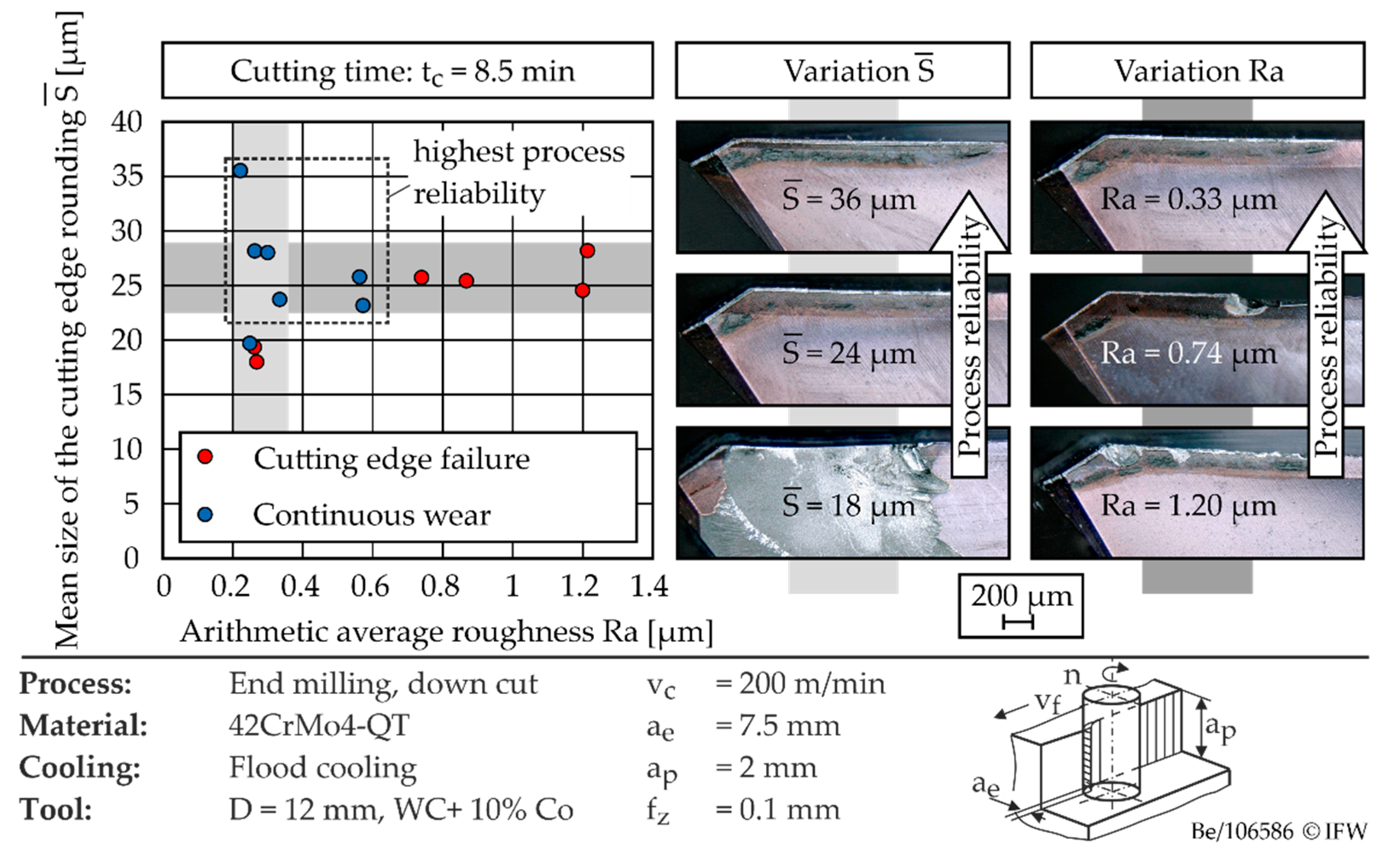
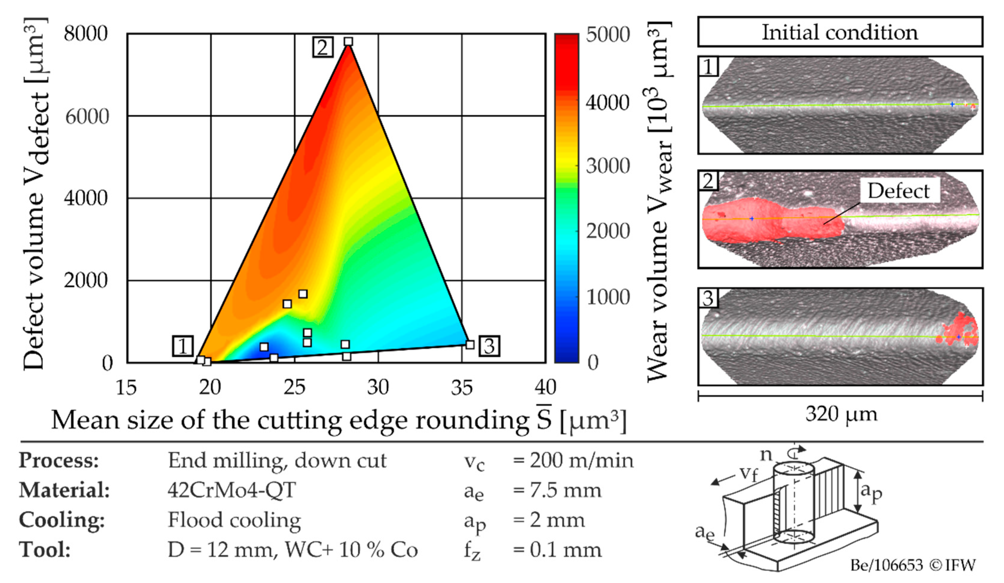
The cutting investigations were carried out on the 4-axis machining center Heller MCi16 using Blaser Vasco6000 (10% Emulsion) as cutting fluid. The quenched and tempered steel 42CrMo4-QT was used as workpiece material. The process parameters were set to a cutting speed of vc = 200 m/min, a feed per tooth of fz = 0.1 mm, a depth of cut of ap = 2 mm, and a width of cut of ae = 7.5 mm (down milling). The analysis of the wear behavior was carried out at defined operating times. The main forms of wear identified for all tools were continuous crater wear at the cutting edge or sporadic micro-breakouts along the cutting edge. The latter were detected in particular when using tools with a sharp cutting edge. For qualitative evaluation of the wear characteristics and identification of the main wear areas, microscopic images were taken in the first step. Due to the existing wear characteristics, the wear volume was selected as a quantifiable parameter for analyzing the wear behavior. To determine this, the areas affected by wear were then measured optically using the Alicona Infinite Focus G5. Subsequently, different methods were evaluated with regard to their suitability for determining the wear volume. A software module of the measuring device used offers the possibility of a so-called differential measurement, which enables a quantitative comparison of two sets of measurement data on the basis of their volume differences. The software determines a volume above as well as below the reference profile. This initially requires the operator to specify an error threshold, which, however, has a large influence on the determined defect volume. In addition, the evaluation requires a considerable amount of time. Due to this, an alternative method for determining the wear volume was developed. Here, the mean profile of the worn cutting edge is determined and automatically aligned with the reference profile of the non-worn cutting edge. These two profiles are output in the form of XY coordinate sets and used for automated determination of the wear volume using Matlab. In addition to achieve a precise determination of the wear volume, this method offers a high degree of automation, which means that a large number of milling tools can be examined at small intervals of the cutting duration.
Figure 8 shows the wear behavior of coated cutting tools as a function of the mean size of the cutting edge rounding and the arithmetic center roughness value.
The microscopic images show that the underlying wear mechanism is significantly influenced by the cutting edge rounding. The latter determines the stability of the cutting edge and, thus, the resistance to cutting edge failure. When the cutting edge rounding is increased from 18 µm to 36 µm, the probability of sporadic cutting edge breakouts decreases significantly. The medium cutting edge rounding
is defined as follows:
In this context, the cutting edge sections on the rake face
Sγ and on the flank face
Sα are defined as the distance from the cutting edge of an ideally sharp cutting edge to the detachment point on the rake or flank face [
6]. Thus, when medium cutting edge rounding of
> 20 µm is used, primarily continuous wear occurs in the area of the cutting edge rounding. When using tools with
> 20 µm, wear is additionally influenced by the condition of the cutting edge. A simplified characterization of the chipping, by means of the arithmetic average roughness value, already allows an initial prediction about the wear mechanism to be expected. In general, the probability of discontinuous tool failure due to cutting edge breakouts increases considerably when the limit value Ra = 0.7 µm is exceeded. However, an exact and statistically validated prognosis of the wear volume by means of amplitude-based roughness parameters, such as the arithmetic average roughness Ra, is only possible to a limited extent. Therefore, more in-depth correlation analysis is performed in the following chapter.
4. Development of a Parameter for Cutting Edge Chipping
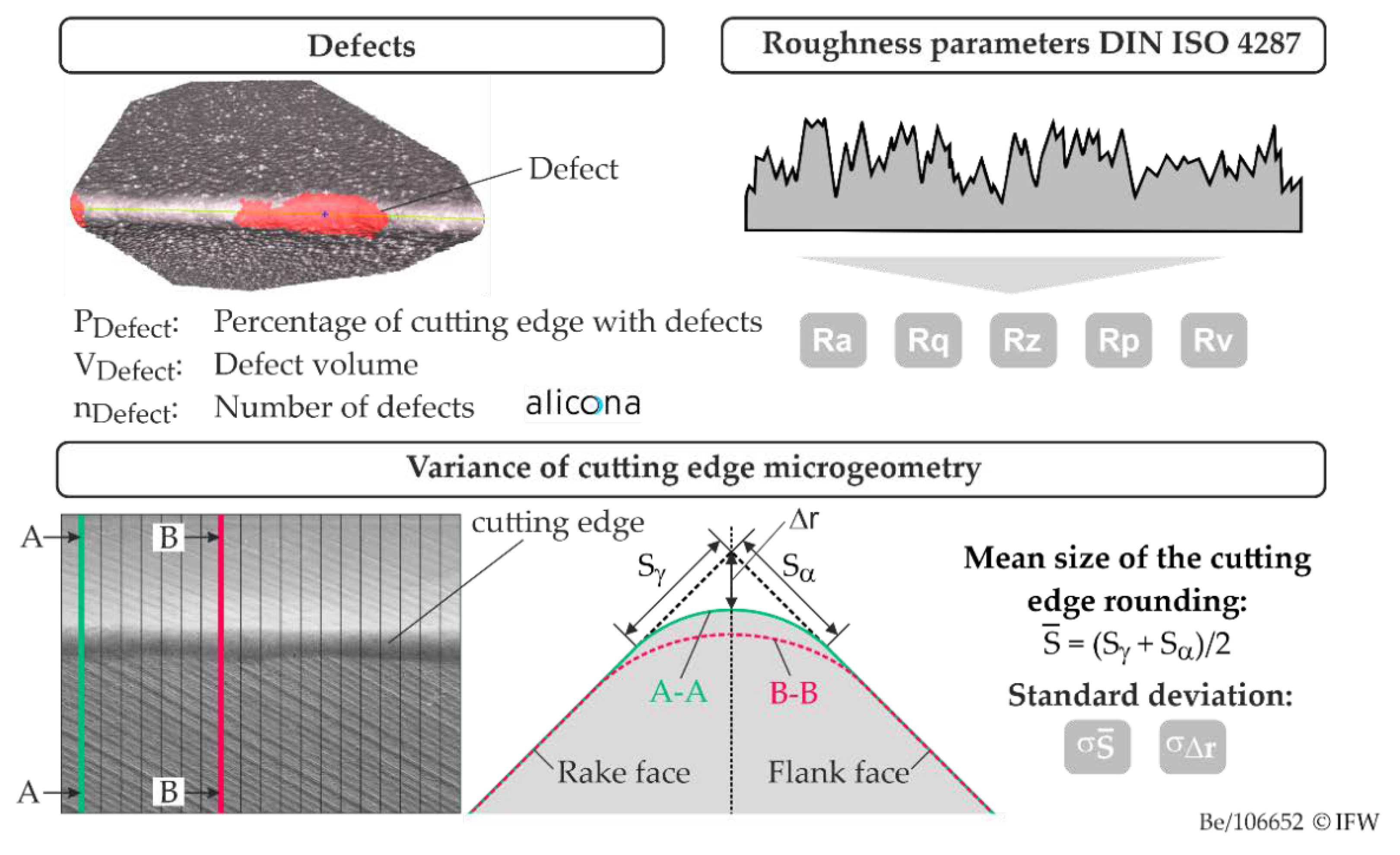
The considered parameters for cutting edge chipping are summarized in
Figure 9. Here, a fundamental distinction is made between roughness and defects along the cutting edge. In the following, defects are referred to as initial flaws induced by the manufacturing process. These parameters were evaluated using the EdgeQuality software extension, which is part of the EdgeMaster module of the Alicona Infinite Focus G5. EdgeQuality offers fully automatic measurement of various parameters for quantifying edge quality. In addition to numerous parameters for defect quantification (length, volume, …), roughness parameters according to DIN ISO 4287 are also output. As threshold values for defect detection, a minimum depth of the defects to be detected of T
Defect = 1 µm and a minimum defect diameter of D
Defect = 3 µm were defined. If the defects are not circular, which is often the case, those cavities are recognized as defects that are larger in area than a circle with the defined defect diameter. In this publication, the defect volume V
Defect, the number of defects along the cutting edge n
Defect, and the proportion of the cutting edge P
Defect that has defects were evaluated to describe the cutting edge chipping.
Cutting edges which are characterized by high roughness after grinding may exhibit significant irregularities with regard to microgeometry after cutting edge preparation. These affect the size of the cutting edge rounding as well as the distance Δr. Therefore, the variance of the cutting edge microgeometry was additionally determined. For this purpose, 100 profile sections were taken orthogonal to the cutting edge. Within the scope of work, only symmetrical cutting edge roundings were considered. Therefore, the mean cutting edge rounding was used. Finally, the standard deviation of the mean cutting edge rounding , and the standard deviation , were derived as a measure of the irregularity of the cutting edge microgeometry.
In order to derive a suitable parameter for cutting edge chipping, the measured values of the cutting investigations were evaluated using statistical methods. In the first step, Pearson correlation coefficients were calculated between the roughness/defect parameters and the wear volume. The Pearson coefficient r is a measure of the linear correlation between measured values
Xi und
Yi in the range −1 ≤
r ≤ 1 (Equation (1)). For
r = 0 there is no correlation, and for
r = 1 there is a perfect correlation between the considered values.
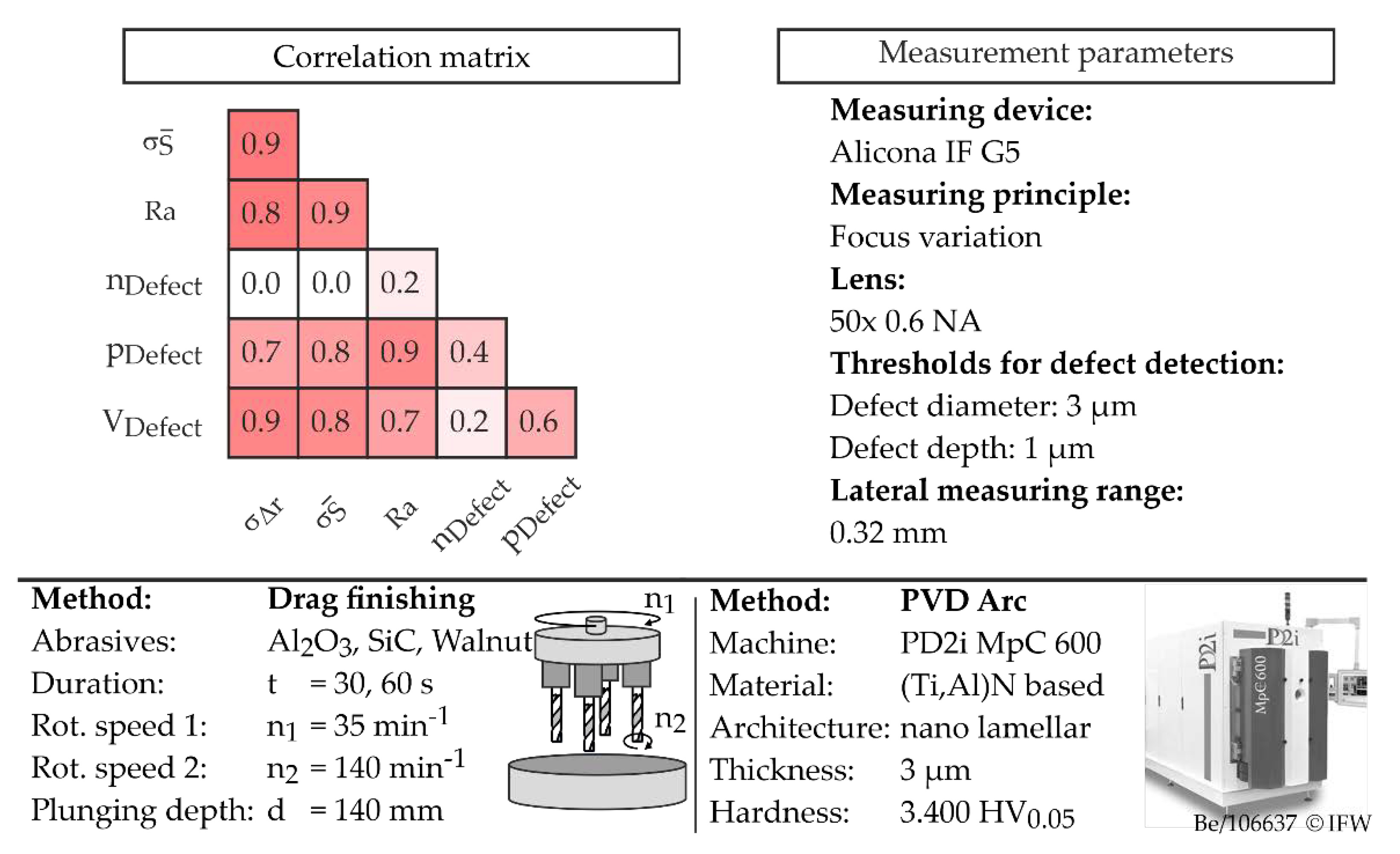
Figure 10 shows the correlation between the investigated parameters for describing cutting edge chipping. It can be seen that the parameters for defect quantification V
Defect and p
Defect show a high correlation with the roughness and the variance of the cutting edge microgeometry. To explain this, the parameters
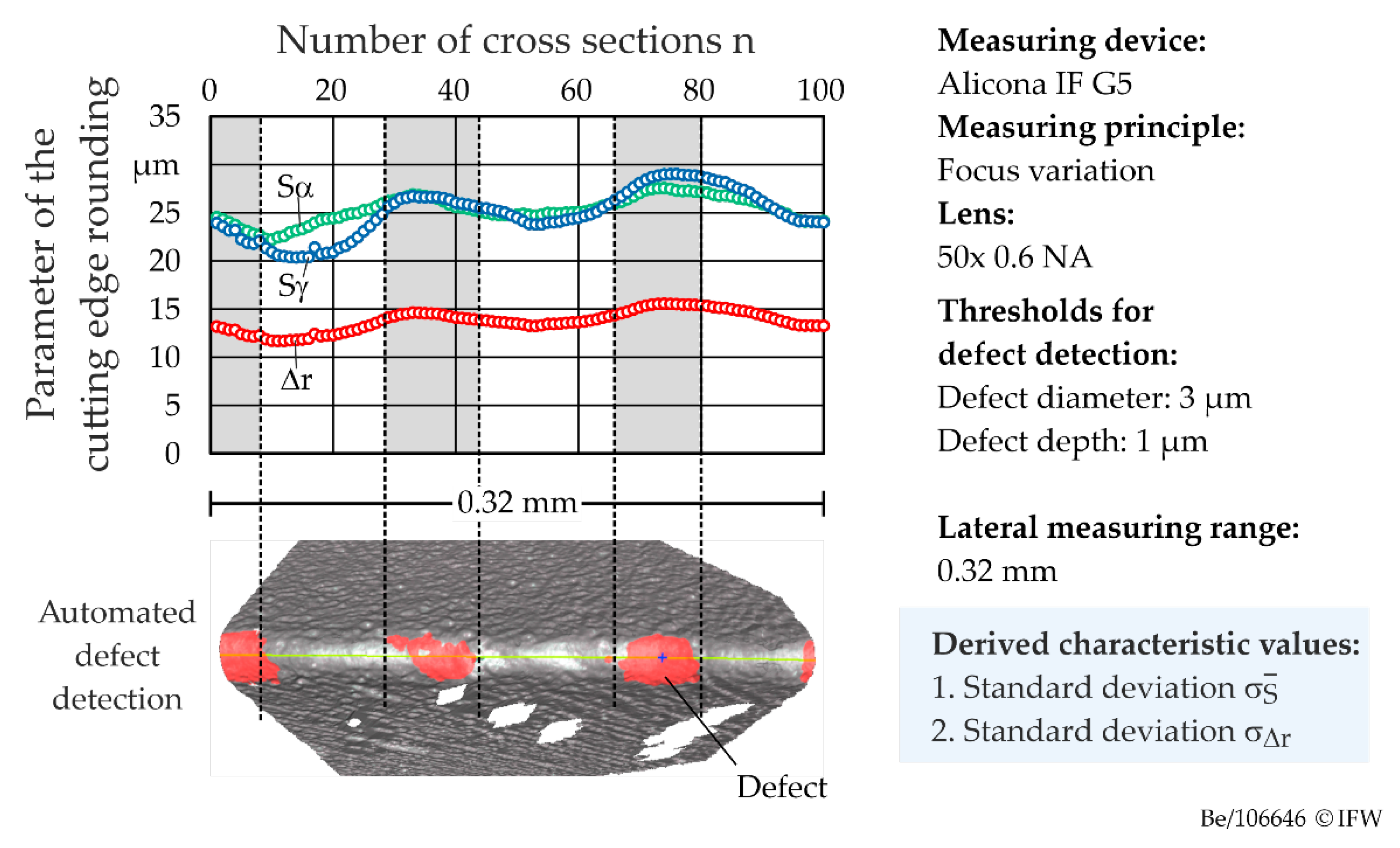
Sα,
Sγ, and Δ
r are plotted against the number of profile cuts in
Figure 11 and compared with the results of automatic defect detection. It can be seen that the respective minima and maxima of the values
Sα,
Sγ, and Δ
r correspond. In addition, areas characterized by higher cutting edge rounding are also detected as defects.
Figure 12 gives an overview of the calculated Pearson coefficients between the different edge quality characteristics and the mean wear volume, depending on the considered parameter range of the cutting edge rounding.
It is shown that when limiting the parameter range from = 18–36 µm to = 23–28 µm, significantly higher correlations are calculated overall than when considering the entire parameter range investigated. This is due to the fact that if the rounding is smaller than a minimum size of = 20 µm, the cutting edge stability, even with the smallest possible chipping, reduces significantly and macroscopic cutting edge breakouts result. This proves the dominant influence of cutting edge rounding over its microtopography.
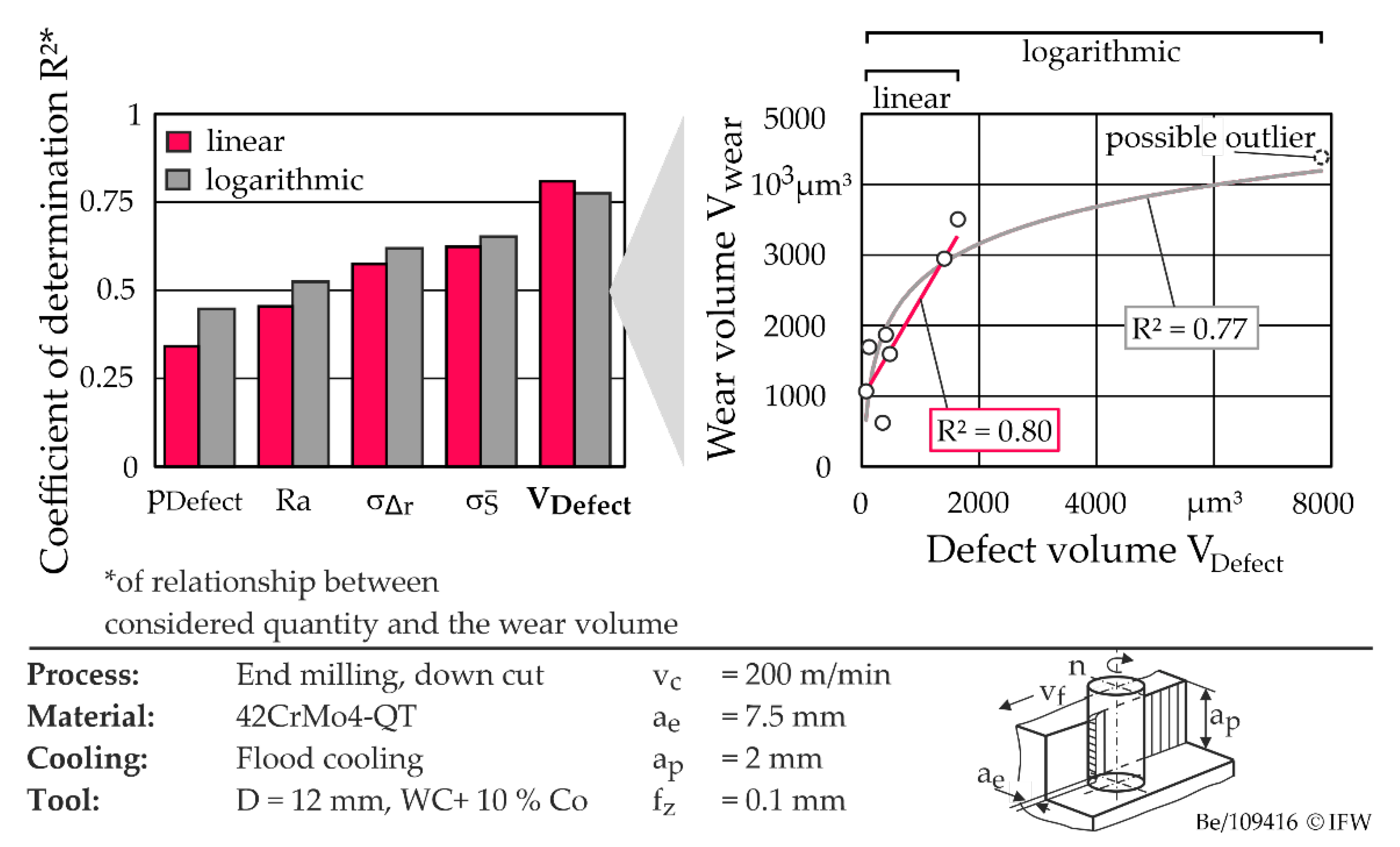
In order to determine a suitable parameter for cutting edge chipping, functional relationships between the wear volume and the considered parameters were derived for tools with cutting edge roundings of
= 23–28 µm. The coefficient of determination R² was used to evaluate the goodness of fit. This is a dimensionless measure that expresses the proportion of variability in the measured values of the dependent variable (here wear volume) that is predictable from the independent variables. In all cases (except for the number of defects), the relationship between the cutting edge chipping parameters and the wear volume can be approximated by means of a logarithmic function. This is exemplified in
Figure 13 (right) for the defect volume. Assuming a logarithmic relationship, the highest quality of fit with R
2 = 0.77 was determined for the defect volume, shown in
Figure 13 (left). Excluding the possible outlier marked in
Figure 13 (right), the data sets show a rather linear behavior. The coefficients of determination obtained in this case show similar values and tendencies to those assumed for a logarithmic relationship. The defect volume is therefore recommended for the characterization of the cutting edge chipping. However, in order to predict tool wear, the size and shape of the cutting edge rounding must be taken into account, in addition to the cutting edge chipping.
The combined influence of cutting edge chipping and cutting edge microgeometry on wear volume is shown in
Figure 14.
The defect volume was used to characterize the chipping. The extent of the defects along the cutting edge is shown for selected tools at the corner points of the parameter range considered in
Figure 14 (right). The defects are marked in red. In
Figure 14 (left), the influence of the cutting edge rounding and the defect volume on the wear volume is shown as a color-coded response surface. The latter was created using cubic interpolation with interpolation points based on the cutting tests. Here, it can be seen that the tool wear increases significantly when the cutting edge rounding is reduced below
= 20 µm, or when the defect volume is increased. During the cutting tests, the highest wear resistance was found for a tool with minimum defect volume and cutting edge rounding with
= 24 µm. With further increase in the cutting edge rounding, a slight increase in the cutting edge wear was observed, which can be attributed to the increasing ploughing effects.
5. Conclusions
Within the scope of this study, the influence of end mill manufacturing process on cutting edge chipping was analyzed, and a parameter was developed which describes the effect of the chipping on the application behavior. In the first step, the process steps of tool manufacture were investigated with regard to their effect on the chipping and the microgeometry of the cutting edge. The milling tools were measured before and after the corresponding process steps. In the case of grinding, the grain size of the abrasive and the grinding strategy were identified as the main influencing variables. In contrast, the influence of the process parameters in the investigated parameter range of cutting speed and feed rate is negligible. In addition, it was shown that the roughness along the cutting edge can be reduced by up to 61% by cutting edge preparation. This effect was demonstrated both with drag finishing and with the use of flexible polishing tools. However, the results also show that the degree of roughness reduction depends on the initial condition of the cutting edge. In addition to grinding and cutting edge preparation, coating and coating post-treatment by drag finishing have only a minor effect on the cutting edge quality.
Based on the findings on the influence of the process chain, milling tools with different edge qualities were subsequently manufactured and used in cutting tests to investigate the influence of the chipping on the application behavior. The cutting tests showed that the wear mechanism, the wear form, and the wear volume are primarily influenced by the cutting edge rounding. When using cutting edge roundings, which have a sufficiently high stability due to their size, the wear is influenced to a large extent by the cutting edge chipping. An increase in the degree of breakouts along the cutting edge and consequently a reduction in process reliability was observed. In addition, a new method for determining the cutting edge chipping could be worked out.
Subsequently, the experimental database was evaluated by statistical methods in order to derive a target-oriented parameter for initial cutting edge chipping. The highest correlation with the wear volume was determined for the defect volume. Taking into account the stochastic character of tool wear, this represents a sufficiently predictive accuracy. The defect volume is therefore recommended as a parameter for characterizing the chipping. However, it was also shown that the size of the cutting edge rounding is a decisive influencing variable, and must be taken into account for the wear prediction.


