
Preliminary Finite Element Analysis and Flight Simulations of a Modular Drone Built through Fused Filament Fabrication


Department of Mechanical and Aerospace Engineering, Politecnico di Torino, Corso Duca degli Abruzzi, 24, 10129 Torino, Italy
*
Author to whom correspondence should be addressed.
J. Compos. Sci. 2021, 5(11), 293; https://0-doi-org.brum.beds.ac.uk/10.3390/jcs5110293
Submission received: 1 September 2021
/
Revised: 20 October 2021
/
Accepted: 3 November 2021
/
Published: 6 November 2021
(This article belongs to the Special Issue Analytical, Numerical and Experimental Methodologies for the Analysis of Multilayered Structures)
Abstract
:This paper discusses the architecture and preliminary design of an Unmanned Aerial Vehicle (UAV), whose actual operative scenario and required performances drive its flying configuration. The UAV is a multirotor and can be adapted to be used as a tricopter, a quadcopter, a hexacopter, and an octocopter: the number (and consequent arrangement) of the arms modify its performance. Customization is combined with the concept of additive manufacturing, as all components are designed to be produced in Fused Filament Fabrication (FFF). This approach does not limit the application scenarios of the drone; it is instead a further push in the direction of customization, as it permits continuous upgrades over time. The paper simulates four scenarios and discusses how to optimize performances such as payload, thrust-to-weight ratio, efficiency, flight time, and maximum speed through suitable configurations. Avionic components already available on the market integrate into a customizable and adaptable frame. This analysis reveals the most severe conditions for the structure, and conducts a structural validation of its performance. Validating the functional use of FFF-produced parts is challenging due to the anisotropic behavior of the parts. However, some structural elements are thin-walled and enjoy being printed with a 100% linear infill. A simplified approach to those elements has already been proposed and validated through a parallel with UniDirectional Composites, whose 2D testing procedures and methodologies have been derived and adapted. An FEA of some elements of the frame is conducted, using shell elements to discretize the geometry. A proper definition of their mechanical response is possible because the constitutive model is not isotropic a priori but reflects the behavior of the finished parts. The tensile strength variability in the material reference system is high: a component-by-component comparison proves the design to be adequate and measured to the surrounding conditions; however, it highlights the absence of a defined failure criterion.
1. Introduction
The interest in Unmanned Aerial Vehicles (UAVs) and their employment is constantly expanding. Their application and, consequently, their characteristics are very different; they have a range of uses spanning from hobby to military purposes [1]. Multirotors UAVs are of particular interest because they can take off vertically, keep themselves in a fixed position in space (hovering), feature great agility, and move at significant speeds. They have an extended range of dimensions, from micro aircraft, of only a few centimeters, to aircraft weighting up to 2000 kg [2].
The continuous development of avionic components and their miniaturization has increasingly expanded the type of missions in which these aircraft can be used [3,4]. Application includes areas such as aerial, amateur or professional, photography, surveillance [5] and inspection services [6], and search and rescue missions [7]. Recently, some commercial operators have been testing their application to logistics networks. The design process of a UAV is explicitly driven by mission requirements, which more specifically translate into performance requirements that the aircraft must deliver. Multirotors base their operation on a set of propellers driven by an equal number of motors joined to a rigid airframe. The flight management strategy relies on sensors and electronic speed controllers; differential control of the individual thrust generated by each propeller allows the control of all the degrees of freedom and all flight maneuvers [8]. Sizing the performances of the propulsion system components and choosing them is a crucial step; their interdependence not only allows lifting and moving the UAV but also results in flight performances. An even number of engines characterizes the most common configurations [9], and therefore an even number of propellers, arranged on the same plane. As a general guideline, a higher number of propellers increases the reliability of the UAV [10], and at the same time, the load capacity. However, a higher number of thrusters affect flight time. Each propeller develops a force perpendicular to its plane, which translates into a moment matched to the core. The distribution of forces and moments depends on the geometric arrangement of the elements of the propulsion system, and affects the flight performance and the possibility of surviving an actuator failure. Controllability in critical conditions needs to be evaluated, weighing the risk of losing the aircraft and the payload. Payload capacity is a crucial aspect for some applications; however, increasing it leads to a decrease in agility and maneuverability due to the parallel increase in inertia [11]. This cannot always be tolerated because specific applications require rapid response capacity [12] and robustness to external actions. As anticipated, the electronics, the propulsion system, and the batteries (in general, the drive) must be effectively sustained by a frame, designed and validated to support all the inertial and non-inertial loads the UAV will undergo during each mission. The most common designs feature a central case/core, from which several arms branch off. Each arm houses a motor at its tip and can be connected to the body with a more or less extended fillet or be decidedly cantilevered. In this configuration the frame undergoes different stresses: the torque generated by the engine, the bending at the arm root, any impact on landing are just some of them [13]. Additive manufacturing brings undoubted economic and design benefits to aerospace applications because it allows iterating the design/manufacturing process until reaching the geometry best fitting the project specifications [14]. Aluminum, carbon fiber, glass fiber, and various polymers are some examples of commonly used materials. The design requirements are, as a rule, meant to reduce the weight, to increase the payload while maintaining a fair stiffness, to limit excessive deformations under load. Presently, the advancements and diffusion of Computer Assisted Design (CAD) systems, even among end-users, coupled with the ease of access to additive manufacturing technologies and Rapid Prototyping, have allowed a large community of enthusiastic creators to become passionate about the world customized UAVs and experimental. Several examples are reported in the literature:
- the UPenn Piccolissimo drone [15], the smallest flying vehicle designed by the University of Pennsylvania; it features a single propeller, but a spinning body, which has been produced in 3D printable polymer;
- the X VEIN drone [16], an open-source project developed for disaster response. It features a lattice structure, which results from a topologic optimization and takes advantage of the additive strategy for its evolutive shape;
- the Tundra-M drone [17], a quadcopter whose central body and arms are produced via Selective Laser Sintering (SLS); this gave the opportunity to iterative optimize its geometry looking for extreme flight conditions scenarios;
- the Iris+ drone [18], whose frame parts can be printed via Fused Filament Fabrication (FFF) and assembled by the final users, together with the electronics provided by the designing company;
- the Skeleton X-14 drone [19], a quadcopter with an FFF-printable single-piece body, home built by the final user, whose peculiar design allows a partial view of the interior components.
Polymers can suit well the UAV context [20,21]. The limited loads and moderate dimensions of the frames make those parts compatible with FFF-processed polymers; in the view of final components manufacturing, the compliance of the design performance criteria needs to be validated. Any part designed for aeronautical applications imposes a fragile balance between the regulated safety limits and the minimization of the operational weight due to the demanding need for lightweight frames [22]. The mechanical validation of the structural performance of printed parts is an open-ended obstacle [23]. The processing parameters [24] as well as the suite that generated the toolpath [25] affect the mechanical performance of the parts. Even having established those variables, a part-to-part variation and an intra-part variation complicate the analysis and add up to an anisotropic response under load [26]. The 100% linear infill strategy simplifies mechanical characterization and analysis because it traces the anisotropic behavior back to a mild orthotropy. Overlapped layers and filament deposited along with defined directions induce an overall directionality in the mechanical properties [27], to be taken into account to assess how the part behaves under load. The feedstock material properties are unreliable; they significantly differ from those of the finished part [28]. A satisfactory prediction of the performance of the part is possible only if the material constitutive model reflects the actual behavior of the components.
This paper focuses on PoliDrone, a modular UAV built through FFF. Its preliminary design received a comprehensive but initial discussion in [29]; this work presented the motivation and discussed the platform by proposing the preliminary geometrical design of the components. They reflected the principle of customization, but they had not yet undergone any iterative optimization process. The authors speculated several application scenarios in anticipation of discussing the flight performance; this result was followed by a prior optimization work on the geometry of the elements in [30]. Both works successfully described the structural components from a functional point of view but highlighted how further, and more profound optimization was necessary to limit the frame weight. In previous work [31], the authors validated a macromechanical approach to the problem, allowing an excellent prediction of the behavior of parts under load. The mission performances of the drone are the starting point for an application example of this approach. The elements of the arms are the investigated frame components; their shape fits the preliminary validated application field of the method.
2. Design of a Modular Drone
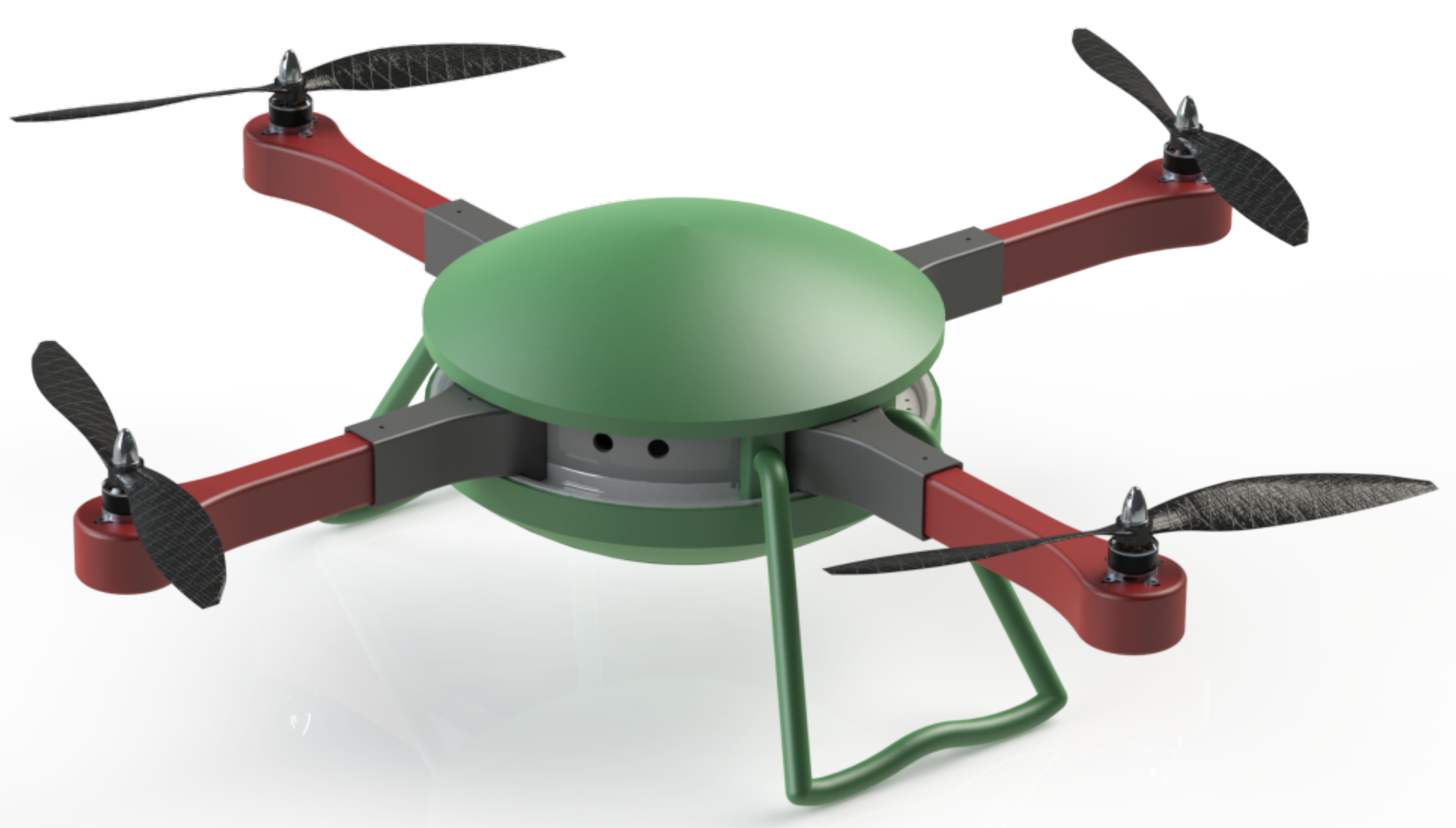
The key and innovative feature of this UAV falls into the idea of customization. The design and architecture of the drone are not unique and fixed a priori; the choice between different options is left to the end-user, which is driven by the operative scenario and by the required performance. The patented [32] idea involves a multirotor geometry, with customizable arms, motors, and propellers number. This idea implies that the user can customize the design of the aircraft: following the mission requirements, the UAV configuration can be adjusted to optimize performances such as payload, thrust-to-weight ratio, efficiency, flight time, and maximum speed. Figure 1 shows an example of the architecture in detail.
The body consists of a primary and central element with circular symmetry. The architecture provides that all the avionics, such as the Flight Control Unit (FCU), GPS antenna, electronics, and battery are housed inside to make this possible. From its assembly derives an external track, which runs in a circumferential direction on its outer perimeter. The UAV arms are grafted onto this track in a variable number between 3 and 8: it is up to the end-user to select their number. Each one can be equipped with a single motor (S) on the upper side; a second rotor can also be added to the lower side, thus switching to a double (D) configuration. Furthermore, it is possible to add an inflatable component for each arm to ensure a water landing or shock absorption in challenging scenarios involving the risk of hard landings, which turns the configuration into an amphibious (A) one. This work narrows the analysis to the defined set of designs listed below:
- S3A-C: Single motor // 3 Arms Configuration,
- S4A-C: Single motor // 4 Arms Configuration,
- S6A-C: Single motor // 6 Arms Configuration,
- S8A-C: Single motor // 8 Arms Configuration.
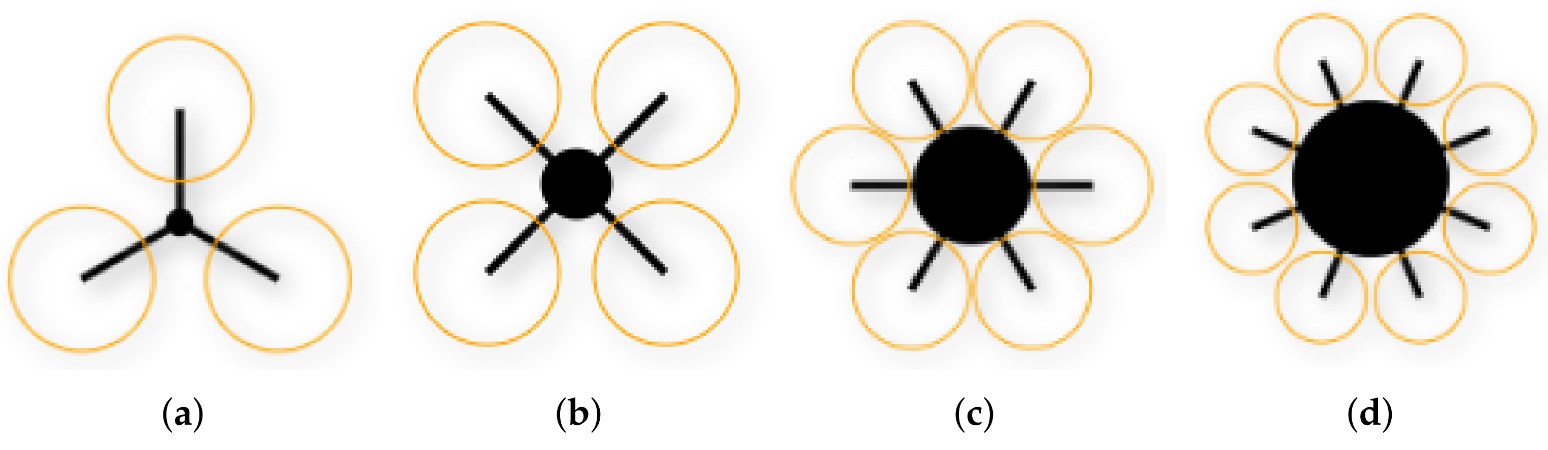
The four configurations are also detailed in Figure 2.
In all these configurations, the spatial arrangement of the arms cannot be random but is predetermined to ensure stability and allow an effective flight control strategy. Twelve anchor points are arranged in the perimeter direction; a table guides the final user in their positioning. The arms are a sort of external plug-and-play device to simplify the user experience. For this reason, in addition to housing the engine and propeller, each arm carries the Electronic Stability Control (ESC) and is equipped with a dedicated socket to connect them to the central element. A complementary socket is present in each anchor point of the central element. Once a new arm has been installed and connected, the control unit evaluates the arms number and spatial arrangement. If this corresponds to a valid configuration, it automatically updates the flight management strategy.
2.1. Design Requirements
The possibility to modify the UAV configuration (that is, the number of arms, therefore of engines and propellers) represents a crucial challenge for the architecture design. This challenge reflects on the structure through a scheme based on a universal main structure, fitting each setup. This shrewdness makes the assembly and disassembly simple operations to the final user. Such modularity can be achieved if:
- all configurations work with the same avionics, electronics, propulsion system, and battery,
- the control unit is designed to identify and manage all the setups,
- the battery is adequately sized for all the configurations.
The choice of avionics, electronics, propulsion system, and batteries considers the performance of each setup. Requiring the end-user to replace some elements between a configuration and another would contrast the modularity requirement. A further fundamental parameter in the architecture definition is the UAV maximum take-off weight (MTOW). The Italian regional regulations on UAV operations published by the Civil Aviation Authority (ENAC) sorts drones in terms of their weight, providing significant simplifications if the MTOW is less than 2 kg. The "Remotely piloted aerial vehicles Regulation" [33] reads:
Remotely piloted aircraft system (RPAS) specialized operations with remotely piloted aircraft (RPA) with an operating take-off mass of less than or equal to 2 kg are to be considered non-critical in any operative scenario, providing that the RPA design criteria and manufacturing techniques result in harmless features that shall be verified in advance by ENAC or by an organization recognized by ENAC.
The attempt to fall back into this category requires careful evaluation but brings with it considerable simplifications. The maximum weight includes that of the payload. However, the latter cannot be assumed a priori, as this choice would limit the possibility of the final user to adapt the UAV to its intended use. Thus, a fundamental requirement is to reduce the weight of the components to a minimum, leaving adequate clearance for the payload.
2.2. Definition of the Components
The elements of a UAV can be summarized as follows:
- propellers,
- DC brushless motors,
- electronic speed controls (ESC),
- Li-Po battery,
- control unit,
- frame.
This section is devoted to studying the avionic components; Section 3 will discuss the frame in detail. Defining avionics is a delicate task, as each choice has repercussions on the overall project and limits the selection of the other parts. This research relied on the comprehensive database of commercial components available in XcopterCalc, searched through specific filters and wizards. The order of the discussion is hierarchical, as all choices affected the following ones. In the first instance, the choice concerned the elements delimited by external pre-requirements only.
2.2.1. Propeller Design
Dimensional and efficiency parameters drive the selection of the propellers. For best efficiency, bigger propellers are best suited. The frame geometry requires that the propellers are coplanar; furthermore, their diameter must guarantee a sufficient clearance between the tips. The four setups require different constraints in this regard, as the arm ends become closer as their number increase: bigger propellers fit the S3A-C setup, smaller one the S8A-C. Modifying the propeller of each configuration allows maintaining high efficiency; in this way, each setup relies on the maximum possible propeller size. Although it involves changing a component depending on the configuration, this solution is simple to apply and inexpensive. The choice relies on the produced trust T and the absorbed power P. Both are a function of the propeller diameter D, the rotational speed n, and the air density , written in consistent units [34]:
The two dimensionless coefficients and are a function of the advance ratio J, which depends on the propeller pitch p:
This is due to the term , which defines the advance of the propeller in one revolution. The pitch is a choice parameter reported by the manufacturers. Explaining this parameter in Equations (1) and (2) allows highlighting two new dimensionless parameters, valid for evaluating the propeller performance.
Besides the diameter, three other parameters need to be considered while designing the UAV architecture:
- trust constant, , which adjusts the percentage of absorbed power converted into thrust. An efficient propeller would see , by converting all the absorbed power into trust; in practice, this value is less than 1.
- power constant, , which adjusts the absorbed power to ideal conditions. A propeller with very narrow blades would see ; in practice, this value is higher than 1.
- pitch, p, its actual effect on thrust is non-linear. An increase in pitch increases the generated thrust but also makes the propeller absorb more power. Above a critical angle, near the propeller stall, the thrusts curve flattens.
Since the diameter of the propeller is already optimized by the choice of the maximum value compatible with each configuration, the choice relied on the models available on the market that maximized and minimized . The datasheet of the identified items is proposed in Table 1. The pitch values relates to manufacturer suggestion; stall with increasing load is avoided as the pitch to diameter ratio is less than .
2.2.2. Motor Design
Brushless motors powered by a direct current source are widespread in multicopters [35]; if compared to brushed motors, they feature higher rotation speed, lower inertia, and a longer life expectancy. The choice follows an initial screening of the models available on the market, which depends on several technical features of the drone:
- all-up-weight,
- propeller diameter,
- number of propeller blades,
- propeller pitch,
- battery-rated voltage,
- frame size,
- number of rotors.
XcopterCalc features a tool for evaluating these input parameters and returning the recommended ranges for three motors performance parameters.
- rpm/voltage, which represents the number of revolutions per minute at which the engine rotates without propeller per Volt;
- minimum motor power;
- minimum Electronic Speed Controller (ESC) size, expressed in A.
With these ranges evaluated, the engine database research can be refined with a view to the optimal model. The UAV understudy features four different setups. Not all the input parameters keep constant across them, translating into other preliminary evaluations and different ideal ranges. The all-up weight can be kept constant, assuming that the drone is fully loaded; the frame size and the battery also, as they are kept in the transition between one configuration and another. The propeller diameter and, in particular, the number of rotors change explicitly. Table 2 keeps together the input and the output parameters, allowing some considerations on the ranges overlap.
The four configurations reflect only partially overlapped recommended ranges: an ideal design holding for all the setup does not exist. Any choice would favor specific configurations while penalizing others. This aspect is not to be evaluated negatively, as the customizability of the UAV will allow the final user to choose the appropriate setup for the mission. An additional evaluation parameter is weight, which is of strategic importance, especially in the higher configurations. NeuMotors model 1230/5Y has been selected from the motors database; Table 3 reports and discusses its datasheet characteristics.
2.2.3. Electronic Speed Controller Design
The Electronic Speed Controller (ESC) connects each motor to the control unit; these components are required in the same number of arms of the chosen configuration. As suggested by the name, each ESC controls the motor speed acting as intermediaries. The ESCs are rated through the maximum current that can sustain. Higher currents can be sustained for a short time; the dimensioning needs to consider the current drawn by the motor, higher with larger propellers and with a high pitch. Table 2 also reports the ranges of minimum ESC size calculated while designing the motor performance. Additionally, here, the four configurations only partially overlapped recommended ranges: an ideal design holding for all the setup does not exist. As for the other components, weight plays an important role, especially in the higher configurations. As its weight increases as the ESC rate increases, a preliminary evaluation evaluated to what level the current drawn by the motor could be contained. As the final results confirm, the maximum current can be kept below 18 A in all configurations. This is a significant advantage, as it allows filtering the ESCs database for the lightest and smallest components. Modularity requires that each ESC is installed inside the hollow part of the arm; keeping the maximum current low allows reducing its size and, consequently, its weight. In this context, the same reasoning made for the motors applies with a view to higher configurations. Table 4 details the datasheet of the identified model.
3. Design of the Frame Components
A further main feature of this project is that only the electronics are supplied, leaving the end-user to print in additive manufacturing and subsequently assemble the structural components. The goal is a flexible platform, which can rapidly evolve and adapt to new and future requirements. This concept also represents a significant advantage from the maintenance point of view: any failures of the frame elements can easily be solved by reprinting the component and reusing the electronics. To this end, the design phase aimed to limit the number of the individual components: they are in total eight. Those that make up the central body are in unit quantity, the others depend on the selected combination. All components are designed to be FFF printed with an affordable and commonly used polymer, PLA, in home desktop printers. PLA is straightforward to process and is a green material, as it is biodegradable under certain conditions. The reduced number of components and the association with the FFF simplify the manufacturing process in producing the essential elements, upgrades to higher configurations, and replacing damaged parts.
3.1. Design Requirements
The frame of the UAV requires a structural evaluation to verify compliance with the performance criteria. Parts featuring complex geometries typically undergo a finite element analysis, in which their shape follows the CAD models without oversimplifications and the description of the geometric and mechanical boundary conditions can be close to reality. As in any structural model, it is necessary to define the mechanical properties of the parts. It is known that FFF-printed parts have an anisotropic behavior [36,37,38,39], which can be as high as 50% within the same component in specific conditions [40]; it is essential to define a strategy to manage this to set up a constitutive model. In a previous work [31], the authors proposed a simplified approach to the problem. The mechanical performance of polymeric 3D-printed components improves as the infill percentage increases [41,42]. When it reaches the maximum value, 100%, the linear infill strategy is the only possible: it requires the filaments to be deposited in parallel, next to each other, all oriented in the same direction.
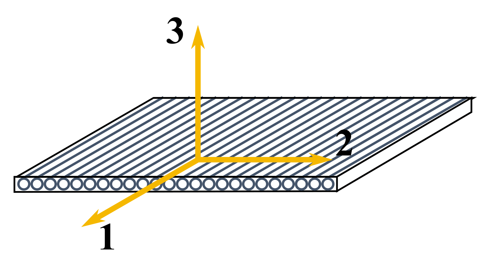
Figure 3 illustrate a single layer with linear infill; note that the filaments define three mutually orthogonal directions:
- Direction 1, i.e., the one of filaments deposition, defined in the building platform;
- Direction 2, it is normal to the filaments and still defined in the building platform;
- Direction 3, which is normal to both the filaments and the building platform.
In this context, the authors speculated that the components might exhibit an orthotropic behavior [43]; under this assumption, the mechanical response would be properly defined by the matrix of elastic coefficients. The literature already provided signs in this sense [44,45,46]; however, it was lacking:
- a coherent definition of the characterization tests setup;
- experimental validation of the predictive capabilities through the mechanical properties defined.
The lack of a standardized procedure required intermediate steps for their design. The authors demonstrated that the mechanical behavior of thin components, printed parallel to the building platform, can be effectively described by the Classical Lamination Theory (CLT) [31]. Their mechanical response is properly defined by the matrix of elastic coefficients; tensile and shear tests can be derived and adapted from those provided for UniDirectional Composites (UDCs). The parallel in Figure 4 justifies the idea. The geometric similarity is undeniable: long elements develop along with a preferential direction in both cases, the fibers in UDC laminate and the filaments in FFF parts. The laminate origins from a set of stacked UDC laminae, the FFF part from linear infill layers.
Outside the building platform and its parallel planes, the authors studied the mechanical behavior along direction 3 [47], proposing a comparative study between tensile and compressive behavior and evaluating the phenomenon of plastic buckling. The authors also demonstrated in [47,48,49] that the compressive strength is always higher than the tensile one in the direction under investigation.
The left columns of Table 5 summarize the mechanical properties that have been determined experimentally; the right columns report the mechanical properties provided by the manufacturer. E, , and G denote a Young modulus, a Poisson ratio, and a shear modulus, respectively; a tensile proportional limit, a tensile strength, and a shear strength. The experimental properties have been determined on specimens manufactured with the printing parameters reported in Table 6.
The feedstock material datasheet reports a single elastic coefficient and a single tensile strength; these data imply that the finished parts would have an isotropic behavior. However, experimental data show that this is not the case. The first result is that the experimental values referred to the 3D-printed polymer are lower than those declared for the feedstock material: the finished parts are less stiff and resistant. In addition to this, the polymer behaves differently along with the three principal directions: the elastic moduli measured in direction 2 and 3 are similar but lower than that recorded in direction 1. The distinctions are even more pronounced while considering the tensile strengths. These results have important implications concerning structural analysis: a first approach could consider the datasheet mechanical properties, but they are inadequate in predicting the mechanical response as they globally overestimate the stiffness. At the same time, they are inaccurate in defining the safety margins as they also overestimate the tensile strength. The results of the characterization campaign allow overcome some of those limitations, but they deliver others.
A stiffness matrix limits the application field to two-dimensional structures; furthermore, the principal directions in the material reference system lie on the building platform. Thus, two-dimensional parts, parallel to the build plate, are the only conditions in which the approach received validation. It is not capable, at the moment, of analyzing any geometry; this will be possible once the mechanical behavior will be defined up to the stiffness matrix. At the moment, the structural validation of the multicopter is limited to the mechanical response of some definite components fitting the previous definition due to their shape and boundary conditions.
3.2. Components of the Frame
This section describes the geometry of the structural elements in the optimized configuration and represents the starting point for the subsequent analyses. It will discuss the geometry and functionality of each component, proposing a printing strategy. This last point, coupled with its in-service boundary conditions, will identify the suitable parts for the structure validation.
3.2.1. Main Core Elements
The central body of the UAV consists of an upper and a lower plate. Both the components feature an external (and single) rail: their assembly reveals a circular guide, along which the supporting element of the arms (which will be described in detail below) can slide up to the location required by the chosen setup. As discussed, their spatial arrangement depends on the setup (that is, on the arm number) and cannot be random but predetermined to guarantee an appropriate flight management and control strategy. User-friendliness is essential: 12 anchor point locations are labeled to help the end-user identify them through a guide table.
The exploded view of the two elements appears in Figure 5. Their assembly is intended to house and protect all the avionics; thus, the upper plate comes with a cylindrical wall, enclosing a dedicated volume, and both the plates feature ventilation holes. Both components are prepared for the installation of a payload. However, the supports are not predetermined and fixed; printing its own parts leaves the end-user with the burden of customizing the mounts according to the payload operational requirements.
The plates are 2D components, even if they feature a vertical wall. Their circular geometry requires a concentric infill rather than a linear one. It still needs to be verified if the CLT-based approach also applies to this mesostructure and how to adapt the 2D orthotropic matrix to a reference system in which one of the principal directions is curvilinear (and concentric). Furthermore, once assembled, it is a box-shaped part with distributed loads (the avionics installed inside) and boundary conditions (the arm supports), featuring the same thicknesses of the arm walls. These conditions reduce its criticality in service.
3.2.2. Arms
The arms are the key elements of the frame. Each one is an assembly featuring a box shape. It comprises three components: an upper and a lower part and a mount in-between the first two and the central body. Each arm carries a motor, together with its propeller. The upper element top surface features a set of anchor points needed to fasten the motor metal casing. A further hole allows sufficient clearance for the lower part of the rotor axis. The arm assembly box shape defines a space housing the arm electronics and, in particular, the Electronic Speed Control (ESC). All these features make the arm an all-in-one device, ready to go upon connection. The complete component can be assembled and disassembled as needed. The mount connects the two arm elements to the central body; its front shape is designed to accommodate the two remaining parts of the arm, while the rear mates with the circular guide of the core. The box shape of the mount is functional to the wiring and allows the connection to the sockets of the core. The graphic rendering of Figure 6 highlights those features.
To be assembled, the upper and the lower part run through the mount, which takes place into the guide. All elements are bound through removable metal fasteners. A single pin prevents the two parts from sliding inside the mount and ensures an optimal length for the arms, functional to the propeller clearance in all the setups. A pair of pins constrains the supporting mount to the core and binds the two central plates simultaneously. Figure 7 reveals the assembly of an arm and the core.
Each arm can be compared to a beam, loaded by a point load at the front, pinned on the other. Its shape is that of a thin-walled box-like cross-section. Excluding the support, each arm consists of two almost mirror-like elements, featuring mm thick walls. Both feature a flat and extended bottom surface, which fosters printing both the parts with this surface adhering to the build plate (see Figure 8a,c). Bending will be the main effect; consequently, a good printing approach consists of arranging the filaments parallel to the longitudinal direction to exploit the higher stiffness and strength of this material direction. The support is an individual part, with a similar printing strategy: it can be produced with two faces parallel to the building platform. Since the right-end region features an increased thickness, and the central section an empty socket, the part requires some support element for production, as presented in Figure 8b,d. Bending is even more critical for this element, as it is positioned at the root, next to the constraint. For this reason, it is helpful to exploit the higher stiffness and strength of material direction 1 by arranging the filaments parallel to the longitudinal direction. Printing the part with its longitudinal axis arranged along the vertical direction would reduce the need for support material; however, it would be risky, as bending tensile/compression would develop along with direction 3, which is the weaker. In these components, bidimensionality and the linear infill coexist. They are also the most critical, given their boundary conditions. The vertical walls issue exists; however, given that they are thin and subjected to bending and that the axial stress for bending develops in the longitudinal direction, a fair compromise to analyze them can be speculated.
3.2.3. Domes and Landing Gears
The upper and lower spherical covers act as a further shield to the electronics housed in the core, employing their external surfaces to support different components. Of particular interest is the lower dome: it defines the volume and the shape, useful for installing a customizable payload. They also help the drone in flotation in the case of ditching. One of the two spherical domes can be removed if the payload needs to be in sight of the external environment (e.g., traditional and thermal cameras). It can be replaced with a transparent element to keep the protection function. Both components are strongly three-dimensional parts, which makes them unfit for a CLT-based FE analysis. Furthermore, from a static point of view, they are not critical parts as they are just shelters. Their impact resistance and damping capabilities should be verified, but this is outside the scope of this paper.
Landing gears support the UAV on the ground, ensuring a sufficient ground clearance in landing. They have a cylindrical shape and end with two dedicated supports, fitting the core circular guide. They are placed in a symmetrical position, one opposite the other and straddling one arm. From a mechanical perspective, they could be compared with unidirectional (columns) elements. However, the end supports prevent them from being printed along a defined direction of the 3D-printing reference system. As a consequence, they also are unfit for a CLT-based FE analysis. Furthermore, they work in compression; given the UAV weight and the compressive strength of 3D-printed PLA, they are definitely oversized. The reflection on the impact resistance and damping capabilities also applies here.
The frame weight is crucial in defining the aircraft setup, evaluating its performance, and assessing the maximum payload. It must also deal with the maximum take-off weight required by the regulations. Schematically, it is a function of:
- the geometry of the elements,
- the polymeric material,
- the actual setup (e.g., the arm number).
Table 7 discusses the bill of materials of the different configurations; it also reports the individual weights of each component. The volumic estimation has been made through CAD; the weights speculate that the components have been printed through Fused Filament Fabrication using PLA and that a 100% infill featured the printing setup. The last row discusses the total weights resulting per each configuration.
4. UAV Virtual Testings
The operational configuration of the drone, its actual flight performance, and characteristics, together with its preliminary setup and the selected avionic components, are the target of this section. This project employed the simulation software xcopterCalc [51], a powerful tool allowing drone operation simulations with an accuracy in the range . It relies upon physical and mathematical models which can simulate the resulting flight characteristics by defining a configuration setup.
4.1. Model Setup
The configuration setup requires defining all the avionic components (motors, ESCs, propellers, and battery), together with the flight environment and the frame configuration. The geometric specifications and the frame weight vary through the different setups: this UAV is more complex than a conventional project. For this reason, the study of the performance has been repeated for each design. In these, the structural weight changes (see Table 7), while the geometric specifications keep constant as expressed in terms of frame size, double the length of an arm, from the center to the engine. The avionic components are discussed in Section 2: they kept constant across all the designs, exception made for the propellers. The performance reflects a 6000 mAh, V battery used up to .
Flight Environment
The environment is a further parameter affecting the simulations. Its characteristics influence flight performance as they enter the physical and mathematical models through the air density. The field elevation, the mean air temperature, and the pressure are the starting data. Those parameters do not geographically limit the UAV; however, with a view to a future validation of the performance, they reduce the degrees of freedom of the system and allow comparison with the flight tests directly. It is assumed that the test flights will be carried out at the facilities of the Politecnico di Torino; the starting point of the simulation, therefore, considered the mean flight environment recorded by the weather station of the Università degli Studi di Torino [52] in 2020; see Table 8.
4.2. Analysis Results
This section describes the results of the simulations on the architectures proposed for the aircraft to evaluate their performance. The results are grouped in different tables, discussing homogeneous parameters and comparing them between the four different setups. This outline allows a direct comparison between the configurations.
Table 9 compares the weights distribution across the four setups; the following points are discussed:
- frame: it is that already discussed in Table 7 considering the structural elements of the UAV;
- drive: it considers the motors, the ESCs, the electrical wires, and the control unit;
- battery: it is constant across all the configuration as they consider the same battery;
- all-up: it defines the take-off weight of the UAV without any additional payload;
- additional payload: it evaluates the payload weight that can be carried, considering the 2000 g limit previously discussed;
- max payload: it represents the maximum additional load that such configuration would sustain.
The weight increases while moving through the four configurations, as each arm carries additional elements with it. This modifies the transport capacities of the UAV, reducing them while moving towards higher configurations. From this perspective, the end-user should prefer lower designs if the mission requires a heavy payload.
Table 10 discusses the battery-related performance of the UAV:
- load: it defines the discharge rate of the battery, defined as its capacity divided by the discharge time in hours; lower values indicate that the discharge is faster;
- voltage: it is the calculated battery voltage at the highest current flow.
The table also reports the estimated flight times, assuming the battery is used up to 90% of its capacity:
- the minimum flight time assumes maximum throttle for all the flight long;
- the mixed flight time considers an intermediate scenario between the full throttle and the hovering;
- the hover flight time relies on the hovering plan only.
The considerations are not trivial, as the trend of the variables considered is not monotonous. The eight-arm configuration features the lower load, which indicates a fast discharge and is further confirmed by the shorter hovering time. Therefore, the last setup is definitely to be ruled out when mission time is a critical feature. The hovering time is similar between the first three configurations if the minor differences are excluded. The estimated flight times can be further extended by quickly replacing the battery at the end of the mission. Figure 9 graphically shows the hovering flight time and payload trends moving across the four considered configurations.
Table 11 evaluates the performance of the motors. First, it considers optimum efficiency conditions characterized by the maximum ratio between power delivered and power absorbed. These results come from a dynamometer test of the motor. Values are then compared with two operating conditions, that of full throttle and that of hovering. In all scenarios, the table compares:
- the current draw of each motor, referred to as current;
- the voltage each motor is subject to;
- the Revolutions Per Minute (RPM);
- the absorbed (electrical) and the generated power (mechanical), together with the efficiency (that is, the ratio between the two);
- the estimated temperature of the motor;
- the power-to-weight ratio, which compares electrical power to the all-up-weight.
All those parameters are referred to the single motor, exception made for the power-to-weight ratio.
This last parameter indicates the power that the UAV must develop to lift a kilo; a typical value for multicopters, considered a reference in the hovering phase, is 150 W/kg [53]. More performing and efficient drones can go below 120 W/kg [54]. The S6A-C configuration is the one that performs best from this perspective; it is not characterized by the maximum mechanical efficiency vs. electric, though, as this is a prerogative of the S8A-C. In hovering, the current absorbed by the single motor exceeds that expected in optimal conditions only in the S3A-C configuration; it is gradually lower as the number of arms increases. The effect is that of an increase in efficiency. The current absorbed is also significantly lower than what can be managed by the selected ESC. Each engine operates at average temperature in this flight condition, slightly above ambient temperature, in all setups. At full-throttle conditions, the most critical configuration is represented by the S3A-C, as the current absorbed by the motor exceeds the continuous amperage of the ESC but is still lower than the peak value (30 A). This result guarantees the possibility of exploiting the maximum throttle for short intervals without causing damage or excessive overheating to the component. Furthermore, the maximum engine temperature does not exceed 50 C in any case.
Table 12 summarizes the overall performance of the UAV by summing up the current and power absorbed and power output of the individual motors in hovering and full-throttle conditions. The table also shows the thrust-to-weight ratio, a specific parameter to describe the drone performance and application scenarios. It is not sufficient that a UAV can lift its own weight; to ensure maneuverability, there must be a residual margin of deliverable thrust at full throttle [55]. 1:1 means that at full throttle, the thrust generated by the motors equals the weight; flight is possible if the multicopter retains a residual percentage thrust of at least 20%. Starting from the minimum value of , typical values and applications are the following [56,57]:
- 1.2–1.5: indoor flight, no wind;
- 1.5–1.9: gentle flying under the light wind, good maneuverability;
- 1.9–3.0: heavy wind, excellent maneuverability;
- 3.0–5.0: acrobatic, racing.
The results show that all configurations feature higher ratios than the threshold value, ensuring the least maneuverability. The minimum falls in correspondence with the eight-arm design and is equal to 1.8:1; this indicates that the UAV can be hoovered with just over half throttle. The maximum value is a prerogative of the six-arm setup, characterized by excellent maneuverability, even in heavy wind conditions, with values at the limit of aerobatic/racing UAVs. The S4A-C configuration keeps these features; its thrust-to-weight ratio is only slightly below the maximum value. The first setup has an intermediate value, but sufficient to deliver excellent maneuverability: it requires less than 50% of full throttle for hovering flight.
Table 13 closes the picture, providing theoretical estimates of some flight parameters of fundamental importance for the end-user in evaluating the UAV setups application to different scenarios. The table discusses:
- the highest tilt angle the multicopter would sustain in hovering;
- the highest forward speed of the considered setup at full throttle and maximum tilt angle;
- the maximum flight range;
- the maximum climb rate.
The downstream calculation of the last three parameters implies a standard drag, i.e., calculated based on a standard reference geometry and a conservative drag coefficient . The model assumes that in the top view, the UAV has cm wide arms, and the core hub is as big as possible, considering the input frame size and the diameter of the propeller in symmetric design; all the items are supposed to be 10 cm thick. This calculation provides a fair indication of the performance; the actual values will be subject to recalculation once the final geometry has been defined and the drag coefficient evaluated.
In terms of tilt angle, note how the S4A-C and S6A-C setups reach the highest values and are equivalent. The maximum speed is in the order of 50 km/h; even if it is just a relative value, based on the assumed drag effects, it cannot be a choice parameter, as it is aligned between the different setups. The estimated range exceeds 3 km and reaches the maximum value in correspondence with the S8A-C setup; this is the image of the greater efficiency of this configuration. The six-arm setup, on the other hand, features the maximum climb rate. Figure 10 graphically shows the thrust-to-weight ratio and the estimated range trends moving across the four considered configurations.
5. FEM Modeling of the Arm Assembly
The following section proposes a stiffness and dimensional adequacy validation of these components in a severe condition: the multirotor is at its MTOW; it accelerates at the maximum throttle to take off vertically. It is assumed an equal distribution of thrust among the arms; the S3A-C is considered, representing the worst-case.
5.1. Model Setup
The three components have been modeled as three different parts through SolidWorks. Before proceeding with the analysis through the suite MSC Nastran & Patran, the geometry underwent a simplification process, basically removing all fillets. This simplification transformed the assembly into hollow parallelepipeds-like with four orthogonal faces of constant thickness. Then, the output geometry in the proprietary CAD format (.sldprt) has been converted into Parasolid (.x_t extension); such a conversion allows exchanging it to other software. Removing the fillets simplifies the process of converting a three-dimensional geometry into a set of two-dimensional surfaces. The model cannot be directly analyzed with the available mechanical properties, as three-dimensional components require 3D mesh elements, then 3D constitutive models to define the material properties. Each arm element has been simplified through a surrogate shell representation, which used the Create Midsurface tool; Figure 11 shows the outcome.
The figure also presents the global reference system of the analysis: the Y axis goes along with the longitudinal direction, the X points down. The thickness information will be recovered while defining the shell properties, keeping consistency with the original CAD. A partial overlap is present among the representative mid-surfaces; this point also can be fixed in shell properties definition by introducing appropriate offsets. Removing the fillets simplified this process, as it allowed reducing the solid into four surfaces only, for the arm elements, plus four more for the support.
5.1.1. Boundary Conditions
The regulations previously discussed require the MTOW to be less than 2 kg, which is ≈20 N. The Trust-to-Weight (TtW) of S3A-C setup has been estimated to be 2.2:1 (see Table 11), meaning that at full throttle, a trust times the weight can be generated by the engines. Consequently, the thrust due to each single-engine simply derives from Equation (6).
Four anchor points transmit the load from the motor metal casing to the arm through threaded fittings. The load calculated through Equation (6) acts equally on four annuli concentric with the anchoring points of the motor metal casing. The motor is secured to the arm via four bolts; the model assumes that each head rests on an M6 washer, whose external diameter is mm and represents the contact surface. For what concerns the constraints, pinned edges are supposed for the rear region of the support (see Figure 12).
The contact relationships between the surfaces required a coherent definition to match the assembly. The FE model assumes an ideal adhesion between the horizontal surfaces of the upper and lower arm elements and those of the support. It is an idealization of reality, supported by the compression preload due to the fasteners. The model considers a simple contact for what concerns the lateral surfaces, allowing only normal compressive forces to be exchanged, ensuring no interpenetration but not excluding other relative movements. The upper and lower elements of the arm are joined together through the mesh nodes after its definition.
5.1.2. Mesh and Properties Definition
The discretization considered 2D shell elements with Quad4 topology. MSC Hybrid mesher was used, as IsoMesh is not compatible with non-isoparametric surfaces, such as those derived from a solid of a general shape. Hybrid mesher has the benefit of also including triangular elements where needed not to distort the grid. Starting from the Global Edge Length (GEL) suggested by the pre-processor, the solution convergence was verified in terms of the total strain energy and a flag result, the tip deflection. Table 14 and Figure 13 deepen the convergence analysis. It turns out that denser meshes result in practically identical results once excluded from the initial adjustments. Therefore, GEL = 2 has been considered throughout the analysis. This mesh involves 19 elements around the edges of the smaller holes and 32 around the edge of the bigger one (see Figure 14).
Once the mesh has been defined, the upper and lower arm elements have been welded, using the equivalence tool to bond the superposed nodes of different surfaces and delete duplicates.
The element properties definition requires a separate discussion. The manufacturing strategy showed in Figure 8a–d implies that the mechanical behavior of only the upper and lower surfaces of the assembly follows the in-plane mechanical properties of Table 5. The vertical walls of the assembly are still thin surfaces, but they are arranged on the 1–3 plane in the material reference system. The feedstock mechanical properties cannot be used as non-representing the finished part. A fair compromise can be obtained by analyzing the load case of those walls. The bending behavior about the transverse direction is the main effect, resulting in axial stresses along the longitudinal direction. The vertical walls are thin enough to be built with peripheral filaments only; in the rectilinear section of the vertical walls, the longitudinal directions coincide with direction 1 and the transverse with direction 2. The peripheral filaments of the wall make it develop along with the “local” direction 1 even in the curved region. Consequently, the authors defined an isotropic constitutive model through the in-plane direction 1 mechanical properties. It is a simplification endorsed by the previous reasoning and by the mild orthotropy of the material.
2D shell elements rely on First-order Shear Deformation Theory (FSDT), which requires more elastic coefficients than CLT as it is based on a matrix. CLT may be retrieved from FSDT by shear penalization; this allows tracing the constitutive model back to Kirchhoff kinematics. For this reason, out-of-plane shear stiffness coefficients have been set to several order of magnitude higher than the values at stake. To summarize, the FEA considers the following constitutive models:
- A 2D orthotropic material for a single layer, defined through the in-plane elastic coefficients of Table 5. The stiffness matrix has been traced back to the stiffness matrix with appropriate penalties over the shear moduli and . The layers have been laid up with their real raster angle and thickness, thus defining a laminated composite. This model defined the mechanical behavior of the lower and upper surfaces.
- A 2D isotropic constitutive model, defined through the in-plane direction 1 elastic coefficient of Table 5. For consistency with the previous model and to keep the kinematics unaltered, the isotropic coefficients have been supplied in a 2D orthotropic model. It defines the mechanical properties of the lateral surfaces.
5.2. Analysis Results
Figure 15 presents the map of the transverse displacement in the bending direction. Figure 16a,b show the map of the axial component (Y direction) of the stress tensor; the double plot allows displaying the results from both the top and the bottom point of view. Figure 17a,b show the maps of the transverse stress components, in X and Z directions. They might play a marginal role as the mechanical response of the arm is bending: the lower horizontal surfaces undergo tensile stresses; the upper surfaces compressive ones. Axial stresses grow from the arm tip towards the root; the interface regions between the two arm elements and the support show a certain discontinuity due to the different contact nature between lateral and upper/lower surfaces. One of the most stressed regions appears to be that of the anchor point of the motor. The load is applied there, but this also depends on its direction in the model: it points towards X direction and does not follow the rotation of the application region due to arm bending.
The limit values of are MPa and MPa, as shown in Figure 16. They take place in a symmetrical position over the top and the bottom surfaces of the whole assembly; they are also symmetric in the lateral surfaces with respect to a horizontal mid-plane. coincides with in the material reference system in almost all the regions of the assembly because all the filaments point toward the axial direction; this excludes the curved lateral surfaces. The limit values of are MPa and MPa, as shown in Figure 17a. It is defined in the lateral surfaces only because it points along with the thickness direction of the shell elements elsewhere (thus it equals 0). Where it is defined, it coincides with in the material reference system. The limit values of are MPa and MPa, as shown in Figure 17b; the highest values manifest in the motor anchoring region. In the upper and lower surfaces of the assembly, coincides with due to the filament deposition direction. It is not defined in the lateral surfaces (thus it equals 0) as it points towards the thickness direction of the shell elements.
Even if a failure criterion has not been developed, the parallel with unidirectional composites can be exploited once again by evaluating the failure indices through the Maximum Stress Criterion. Figure 18 shows the failure indices in the top and bottom surfaces of the arm; Figure 19 shows those in the top and bottom surfaces of the support. Both the fringes respect Table 5 values for failure limits. The compressive stress limits coincide with the tensile ones; the latter are always lower than the firsts, as discussed in Section 3, so this might be considered a conservative approach. The bonding shear strength is assumed to coincide with the shear stress limit; given the peculiarities of the production technology, and the differences with the actual lamination in composites, it is impossible to split the two effects. The highest value is minimal in both the components, as it keeps below . Please note that an analogous evaluation cannot be performed in the lateral surfaces, where the model assumed an isotropic constitutive model. Figure 20 reports the Von Mises stresses distribution in the lateral surfaces of the support. Those surfaces develop along with the 1–3 plane in the 3D-printing reference system. The highest value, MPa, keeps well below the lowest tensile strength found for PLA in the material reference system. The same applies to all the individual components of the stress tensor, as detailed before.
Although the individual panels have a limited thickness, the cross-section is considerable and offers its highest moment of inertia to the axis around which bending takes place. Further optimization could be attempted; however, it is difficult to achieve at this stage for the following reasons:
- the hollow section is aimed to house the avionics; its horizontal and vertical surfaces guarantee waterproofing in the case of a water landing,
- reducing the stiffness of the arm would result in an increased deflection under the same load, which would modify the application line of the thrust,
- decreasing the wall thickness would reduce the impact resistance of the frame.
6. Conclusions and Future Developments
This work presented the architecture and design of a customizable multirotor. Its customizability allows the end-user to vary the performances of the UAV, adapting them to the required mission profile. This feature is a significant advantage as it enables the platform to adapt and does not require its replacement. This framework integrates non-custom avionics, i.e., components already available on the market; it exploits Fused Filament Fabrication technology for frame components production. By excluding the payload, limited by the MTOW for regulatory reasons, the discussion showed how the individual performance indices do not follow a monotonous trend while moving from lower to higher configurations. The guiding element for the choice of avionic components was the individual weight. This choice is of critical importance from the perspective of modularity, as the transition to higher configurations implies adding additional components to the UAV. The same reasoning can be applied to the structural elements of the frame: their optimization would reduce the Operating Empty Weight and improve its performance and load capacities.
From this perspective, setting the basis for structural analysis is fundamental. 3D-printed components with 100% infill percentage and a linear infill manifest an orthotropic behavior; previous works paved the way for standardizing the in-plane mechanical characterization and validated the analysis results. However, this approach does not allow analyzing any component; it is intrinsically limited to thin parts arranged on the 1–2 plane in the structure reference system. The structural validation is then limited to the mechanical response of some defined elements of the frame.
The analysis proved that the design is adequate and measured to the surrounding conditions; however, the validation could only be performed from the Maximum Stress Criterion perspective. This application example highlights that a failure criterion specifically designed for FFF 3D-printed parts does not exist; failure modes still need to be studied to define specific criteria in this field. The calculated stresses are of an order of magnitude less than the yielding/failure values previously described; in the perspective of a preliminary evaluation of the structural response of those frame elements, the arm assembly can be considered to be validated.
Author Contributions
Conceptualization, S.B. and R.T.; methodology, S.B. and R.T.; software, R.T.; validation, S.B. and R.T.; formal analysis, R.T.; investigation, R.T.; resources, S.B.; data curation, R.T.; writing—original draft preparation, R.T.; writing—review and editing, S.B.; visualization, R.T.; supervision, S.B.; project administration, S.B.; funding acquisition, S.B. All authors have read and agreed to the published version of the manuscript.
Funding
This research received no external funding.
Institutional Review Board Statement
Not applicable.
Informed Consent Statement
Not applicable.
Conflicts of Interest
The authors declare no conflict of interest.
References
- Junaid, A.B.; De Cerio Sanchez, A.D.; Bosh, J.B.; Vitzilaios, N.; Zweiri, Y. Design and Implementation of a Dual-Axis Tilting Quadcopter. Robotics 2018, 7, 65. [Google Scholar] [CrossRef] [Green Version]
- Kumar, V.; Michael, N. Opportunities and challenges with autonomous micro aerial vehicles. Int. J. Robot. Res. 2012, 31, 1279–1291. [Google Scholar] [CrossRef]
- Piljek, P.; Kotarski, D.; Krznar, M. Method for Characterization of a Multirotor UAV Electric Propulsion System. Appl. Sci. 2020, 10, 8229. [Google Scholar] [CrossRef]
- Anweiler, S.; Dawid Piwowarski, D. Multicopter platform prototype for environmental monitoring. J. Clean. Prod. 2020, 155, 204–211. [Google Scholar] [CrossRef]
- Yeom, S.; Cho, I.J. Detection and tracking of moving pedestrians with a small unmanned aerial vehicle. Appl. Sci. 2019, 9, 3359. [Google Scholar] [CrossRef] [Green Version]
- Menéndez, O.; Pérez, M.; Auat Cheein, F. Visual-based positioning of aerial maintenance platforms on overhead transmission lines. Appl. Sci. 2019, 9, 165. [Google Scholar] [CrossRef] [Green Version]
- Briod, A.; Kornatowski, P.; Zufferey, J.C.; Floreano, D.A. Collision-resilient flying robot. J. Field Robot. 2014, 31, 496–509. [Google Scholar] [CrossRef] [Green Version]
- Pitonyak, M.; Sahin, F. Locomotion and transitional procedures for a hexapod-quadcopter robot. In Proceedings of the 2017 IEEE International Conference on Systems, Man, and Cybernetics (SMC), Banff, AB, Canada, 5–8 October 2017; pp. 1447–1452. [Google Scholar]
- Hamandi, M.; Usai, F.; Sablé, Q.; Staub, N.; Tognon, M.; Franchi, A. Survey on Aerial Multirotor Design: A Taxonomy Based on Input Allocation. HAL Arch. Ouvert. 2020, 1–25. [Google Scholar] [CrossRef]
- Mueller, M.W.; D’Andrea, R. Stability and control of a quadrocopter despite the complete loss of one, two, or three propellers. In Proceedings of the 2014 IEEE International Conference on Robotics and Automation (ICRA), Hong Kong, China, 31 May–7 June 2014. [Google Scholar]
- Mahony, R.; Kumar, V.; Corke, P. Multirotor Aerial Vehicles: Modeling, Estimation, and Control of Quadrotor. IEEE Robot. Autom. Mag. 2012, 19, 20–32. [Google Scholar] [CrossRef]
- Rizwan, R.; Shehzad, M.N.; Awais, M.N. Quadcopter-Based Rapid Response First-Aid Unit with Live Video Monitoring. Drones 2019, 3, 37. [Google Scholar] [CrossRef] [Green Version]
- Martinetti, A.; Margaryan, M.; van Dongen, L. Simulating mechanical stress on a micro Unmanned Aerial Vehicle (UAV) body frame for selecting maintenance actions. Procedia Manuf. 2018, 16, 61–66. [Google Scholar] [CrossRef]
- Zhu, W.; Zhang, X.; Li, D. Flexible all-plastic aircraft models built by additive manufacturing for transonic wind tunnel tests. Aerosp. Sci. Technol. 2018, 84, 237–244. [Google Scholar] [CrossRef]
- Piccoli, M.; Yim, M. Piccolissimo: The smallest micro aerial vehicle. In Proceedings of the 2017 IEEE International Conference on Robotics and Automation (ICRA), Singapore, 29 May–3 June 2017; pp. 3328–3333. [Google Scholar]
- Wikifactory. X Vein Drone. Available online: https://wikifactory.com/@yukiogasawara/x-vein (accessed on 22 February 2021).
- Hexadrone. Tundra. Available online: https://tundra.hexadrone.fr/ (accessed on 22 February 2021).
- 3D Robotics IRIS+.MEGAPIXEL. Available online: https://www.megapixel.cz/3d-robotics-iris-433 (accessed on 1 March 2021).
- SKELETON X-14 Quadcopter. CULTS 3D. Available online: https://cults3d.com/en/3d-model/gadget/skeleton-x-14-quadcopter (accessed on 1 March 2021).
- Ferro, C.G.; Brischetto, S.; Torre, R.; Maggiore, P. Characterization of ABS specimens produced via the 3D printing technology for drone structural components. Curved Layer. Struct. 2016, 3, 172–188. [Google Scholar] [CrossRef] [Green Version]
- Buhring, J.; Nuno, M.; Schroder, K.U. Additive manufactured sandwich structures: Mechanical characterization and usage potential in small aircraft. Aerosp. Sci. Technol. 2021, 111, 1–8. [Google Scholar] [CrossRef]
- Goh, G.D.; Agarwala, S.; Goh, G.L.; Dikshit, V.; Sing, S.L.; Yeong, W.Y. Additive manufacturing in unmanned aerial vehicles (UAVs): Challenges and potential. Aerosp. Sci. Technol. 2017, 63, 140–151. [Google Scholar] [CrossRef]
- Dana, H.R.; Barbe, F.; Delbreilh, L.; Azzouna, M.B.; Guillet, A.; Breteau, T. Polymer additive manufacturing of ABS structure: Influence of printing direction on mechanical properties. J. Manuf. Process. 2019, 44, 288–298. [Google Scholar] [CrossRef]
- Mohamed, O.A.; Masood, S.H.; Bhowmik, J.L. Optimization of fused deposition modeling process parameters: A review of current research and future prospects. J. Mater. Process. Technol. 2015, 3, 42–53. [Google Scholar] [CrossRef]
- Peterson, A.M. Review of acrylonitrile butadiene styrene in fused filament fabrication: A plastics engineering-focused perspective. Addit. Manuf. 2019, 27, 363–371. [Google Scholar] [CrossRef]
- Koch, C.; Van Hulle, L.; Rudolph, N. Investigation of mechanical anisotropy of the fused filament fabrication process via customized tool path generation. Addit. Manuf. 2017, 16, 138–145. [Google Scholar] [CrossRef]
- ASTM D52900. Standard Terminology for Additive Manufacturing; ASTM International: West Conshohocken, PA, USA, 2015. [Google Scholar]
- Lay, M.; Thajudin, N.L.N.; Hamid, Z.A.A.; Rusli, A.; Abdullah, M.K.; Shuib, R.K. Comparison of physical and mechanical properties of PLA, ABS and Nylon 6 fabricated using fused deposition modeling and injection molding. Compos. B Eng. 2019, 176, 1–8. [Google Scholar] [CrossRef]
- Brischetto, S.; Ciano, A.; Ferro, C.G. A multipurpose modular drone with adjustable arms produced via the FDM additive manufacturing process. Curved Layer. Struct. 2016, 3, 202–213. [Google Scholar] [CrossRef]
- Torre, R. Mechanical Characterization of ABS and Preliminary Design for a 3D Printed UAV Produced via FDM. Master’s Thesis, Politecnico di Torino, Torino, Italy, 2016. [Google Scholar]
- Torre, R. Theoretical, Numerical, and Experimental Methodologies for Structural Analysis of Polymeric Aeronautical Elements Produced via Additive Manufacturing. Ph.D. Thesis, Politecnico di Torino, Torino, Italy, 2021. [Google Scholar]
- Brischetto, S.; Ciano, A.; Raviola, A.L. A Multipurpose Modular Drone with Adjustable Arms. Patent No. ITUB20155341A1, 5 November 2015. [Google Scholar]
- ENAC—Italian Civil Aviation Authority. Remotely Piloted Aerial Vehicles Regulation; ENAC—Italian Civil Aviation Authority: Roma, Italy, 2018. [Google Scholar]
- McCormick, B.W. Aerodynamics, Aeronautics, and Flight Mechanics, 2nd ed.; Wiley: New York, NY, USA, 1995; pp. 154–196. [Google Scholar]
- Medeiros, V.R.L.; Ramos, G.S.J.G.; Nascimento, T.P.; Lima Filho, C.A.; Brito, A.V. A novel approach for brushless DC motors characterization in drones based on chaos. Drones 2018, 2, 14. [Google Scholar] [CrossRef] [Green Version]
- Durgun, I.; Ertan, R. Experimental investigation of FDM process for improvement of mechanical properties and production cost. Rapid Prototyp. J. 2014, 20, 228–235. [Google Scholar] [CrossRef]
- Uddin, M.S.; Sidek, M.F.R.; Faizal, M.A.; Ghomashchi, R.; Pramanik, A. Evaluating Mechanical Properties and Failure Mechanisms of Fused Deposition Modeling Acrylonitrile Butadiene Styrene Parts. J. Manuf. Sci. Eng. 2017, 139, 242–246. [Google Scholar] [CrossRef]
- Sood, A.K.; Ohdar, R.K.; Mahapatra, S.S. Experimental investigation and empirical modelling of FDM process for compressive strength improvement. J. Adv. Res. 2012, 8, 81–90. [Google Scholar] [CrossRef] [Green Version]
- Ahn, S.-H.; Montero, M.; Odell, D.; Roundy, S.; Wright, P.K. Anisotropic material properties of fused deposition modeling ABS. Rapid Prototyp. J. 2002, 8, 248–257. [Google Scholar] [CrossRef] [Green Version]
- Kazmer, D. Three-Dimensional Printing of Plastics. In Applied Plastics Engineering Handbook; William Andrew Publishing: Norwich, NY, USA, 2017; Volume 2, pp. 617–634. [Google Scholar]
- Griffiths, C.A.; Howarth, J.; de Almeida Rowbothamb, J.; Rees, A. Effect of build parameterson processing efficiency and material performance in fused deposition modelling. Procedia CIRP 2016, 49, 28–32. [Google Scholar] [CrossRef] [Green Version]
- Rodriguez-Panes, A.; Claver, J.; Camach, A.M. The influence of manufacturing parameters on the mechanical behaviour of PLA and ABS pieces manufactured by FDM: A comparative analysis. Materials 2018, 11, 1333. [Google Scholar] [CrossRef] [Green Version]
- Torre, R.; Brischetto, S.; Ferro, C.G.; Maggiore, P. Characterization, in Analogy with Composites Embedding Unidirectional Long Fibres, of PLA Specimens Produced via FFF Printing Process. In Proceedings of the 21st International Conference on Composite Structures (ICCS21), Bologna, Italy, 4–7 September 2018. [Google Scholar]
- Croccolo, D.; De Agostinis, M.; Olmi, G. Experimental characterization and analytical modelling of the mechanical behaviour of fused deposition processed parts made of ABS-M30. Comput. Mater. Sci. 2013, 79, 506–518. [Google Scholar] [CrossRef]
- Li, L.; Sun, Q.; Bellehumeur, C.; Gu, P. Composite modeling and analysis for fabrication of FDM prototypes with locally controlled properties. J. Manuf. Process. 2002, 4, 252–264. [Google Scholar] [CrossRef]
- Casavola, C.; Cazzato, A.; Moramarco, V.; Pappalettere, C. Orthotropic mechanical properties of fused deposition modelling parts described by classical laminate theory. Mater. Des. 2016, 90, 453–458. [Google Scholar] [CrossRef]
- Torre, R.; Brischetto, S.; Di Pietro, I.R. Buckling developed in 3D printed PLA cuboidal samples under compression: Analytical, numerical and experimental investigations. Addit. Manuf. 2021, 38, 101790. [Google Scholar]
- Brischetto, S. and Torre, R. Tensile and Compressive Behavior in the Experimental Tests for PLA Specimens Produced via Fused Deposition Modelling Technique. J. Compos. Sci. 2020, 4, 140. [Google Scholar] [CrossRef]
- Brischetto, S.; Torre, R. An Experimental Comparison for Compression of PLA Specimens Printed in In-Plane and Out-of-Plane Directions. Am. J. Appl. Sci. 2020, 13, 563–583. [Google Scholar] [CrossRef]
- Eryone Galaxy PLA—Data Sheet—Shenzhen Eryone Technology. Available online: https://cdn-3d.niceshops.com/upload/file/Glitter_PLA_Filament[2].pdf (accessed on 24 June 2019).
- xcopterCalc–Multicopter calculator. Available online: https://www.ecalc.ch/ (accessed on 24 March 2021).
- Stazione Meteorologica di Fisica dell’Atmosfera—Università degli Studi di Torino. Available online: http://www.meteo.dfg.unito.it/ (accessed on 10 February 2020).
- Sarghini, F.; De Vivo, A. Analysis of Preliminary Design Requirements of a Heavy Lift Multirotor Drone for Agricultural Use. Chem. Eng. Trans. 2017, 58, 625–630. [Google Scholar]
- Hasan, M.; Qays, H.M.; Jumaa, B.A.; Salman, A.D. Design and Implementation of Autonomous Quadcopter using SITL Simulator. IJCCCE 2020, 20, 1–16. [Google Scholar]
- Dai, X.; Quan, Q.; Ren, J.; Cai, K. Efficiency Optimization and Component Selection for Propulsion Systems of Electric Multicopters. IEEE Trans. Ind. Electron. 2019, 66, 7800–7809. [Google Scholar] [CrossRef]
- Biczyski, M.; Sehab, R.; Whidborne, J.F.; Krebs, G.; Luk, P. Multirotor Sizing Methodology with Flight Time Estimation. J. Adv. Transp. 2020. [Google Scholar] [CrossRef]
- Half Chrome Drones—Drone thrust testing. Available online: https://www.halfchrome.com/drone-thrust-testing/ (accessed on 10 February 2020).
Figure 1.
Graphic rendering of the PoliDrone UAV in the S4A-C configuration: four arms with a single motor/propeller each.
Figure 1.
Graphic rendering of the PoliDrone UAV in the S4A-C configuration: four arms with a single motor/propeller each.

Figure 2.
Graphical representation of the setups considered in the design phase. The elements in these figures are not in scale. (a) S3A-C. (b) S4A-C. (c) S6A-C. (d) S8A-C.
Figure 2.
Graphical representation of the setups considered in the design phase. The elements in these figures are not in scale. (a) S3A-C. (b) S4A-C. (c) S6A-C. (d) S8A-C.

Figure 3.
Material reference system of a layer featuring linear infill. All the filaments are parallel to direction 1, which lies on the building platform together with direction 2. 3 is the out-of-plane direction, orthogonal to the building platform.
Figure 3.
Material reference system of a layer featuring linear infill. All the filaments are parallel to direction 1, which lies on the building platform together with direction 2. 3 is the out-of-plane direction, orthogonal to the building platform.

Figure 4.
Comparison between unidirectional laminae, stacked into a laminate, and FFF layers, piled into a component with a linear infill.
Figure 4.
Comparison between unidirectional laminae, stacked into a laminate, and FFF layers, piled into a component with a linear infill.

Figure 5.
Graphic rendering of the central/main elements of the frame.

Figure 6.
Graphic rendering of the arm assembly. The support is colored in gray; the upper and the lower elements are those in red.
Figure 6.
Graphic rendering of the arm assembly. The support is colored in gray; the upper and the lower elements are those in red.

Figure 7.
Exploded view of an arm assembled with the core.

Figure 8.
Components of the arm: preview of the 3D-printing strategy via FFF. (a) Arm elements, top view. (b) Support, top view. (c) Arm elements, side view. (d) Support, side view..
Figure 8.
Components of the arm: preview of the 3D-printing strategy via FFF. (a) Arm elements, top view. (b) Support, top view. (c) Arm elements, side view. (d) Support, side view..

Figure 9.
Hovering flight time (a) and payload (b) vs. the four different setups.

Figure 10.
Thrust-to-weight ratio (a) and estimated range (b) vs. the four different setups.

Figure 11.
FE model, model setup: surrogate shell representation of the arm assembly for FE analysis.
Figure 11.
FE model, model setup: surrogate shell representation of the arm assembly for FE analysis.

Figure 12.
FE model, model setup: Constraint boundary conditions applied on the arm support.

Figure 13.
FE model, model setup: convergence analysis of the total strain energy vs. the global edge length.
Figure 13.
FE model, model setup: convergence analysis of the total strain energy vs. the global edge length.

Figure 14.
FE model: PoliDrone arm meshed with Quad4 2D shell elements via MSC Hybrid mesher.

Figure 15.
Transverse displacement map (X direction), superimposed on the arm deformed shape. The results are expressed in mm.
Figure 15.
Transverse displacement map (X direction), superimposed on the arm deformed shape. The results are expressed in mm.

Figure 16.
Axial component (Y direction) of the stress tensor map, superimposed on the arm deformed shape. The results are expressed in MPa. (a) Top view. (b) Bottom view.
Figure 16.
Axial component (Y direction) of the stress tensor map, superimposed on the arm deformed shape. The results are expressed in MPa. (a) Top view. (b) Bottom view.

Figure 17.
Transverse components of the stress tensor map, superimposed on the arm deformed shape. The results are expressed in MPa. (a) X component. (b) Z component.
Figure 17.
Transverse components of the stress tensor map, superimposed on the arm deformed shape. The results are expressed in MPa. (a) X component. (b) Z component.

Figure 18.
Failure indices in the top and bottom surfaces of the arm; Maximum Stress Criterion.

Figure 19.
Failure indices in the top and bottom surfaces of the support; Maximum Stress Criterion.

Figure 20.
Von Mises stresses distribution in the lateral surfaces of the support (left) and of the arm (right).
Figure 20.
Von Mises stresses distribution in the lateral surfaces of the support (left) and of the arm (right).


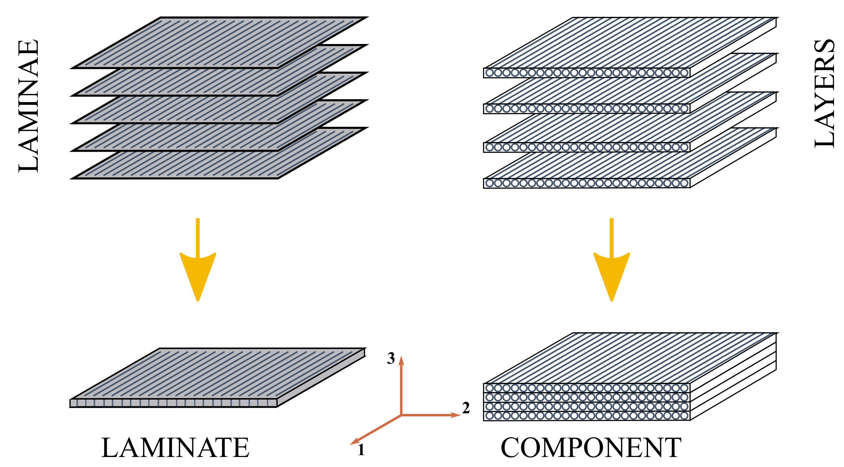
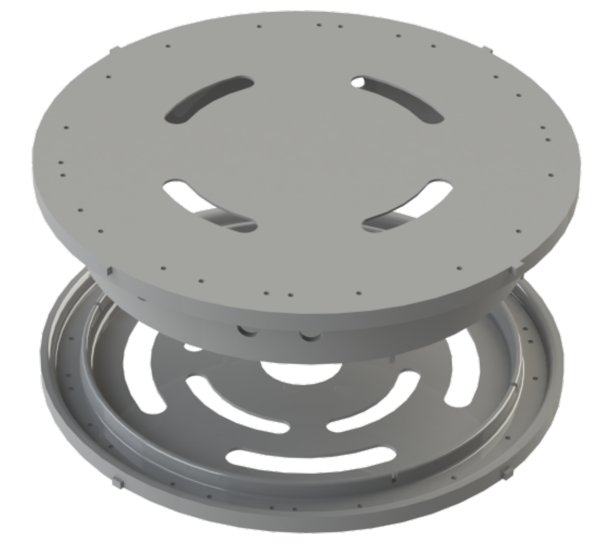
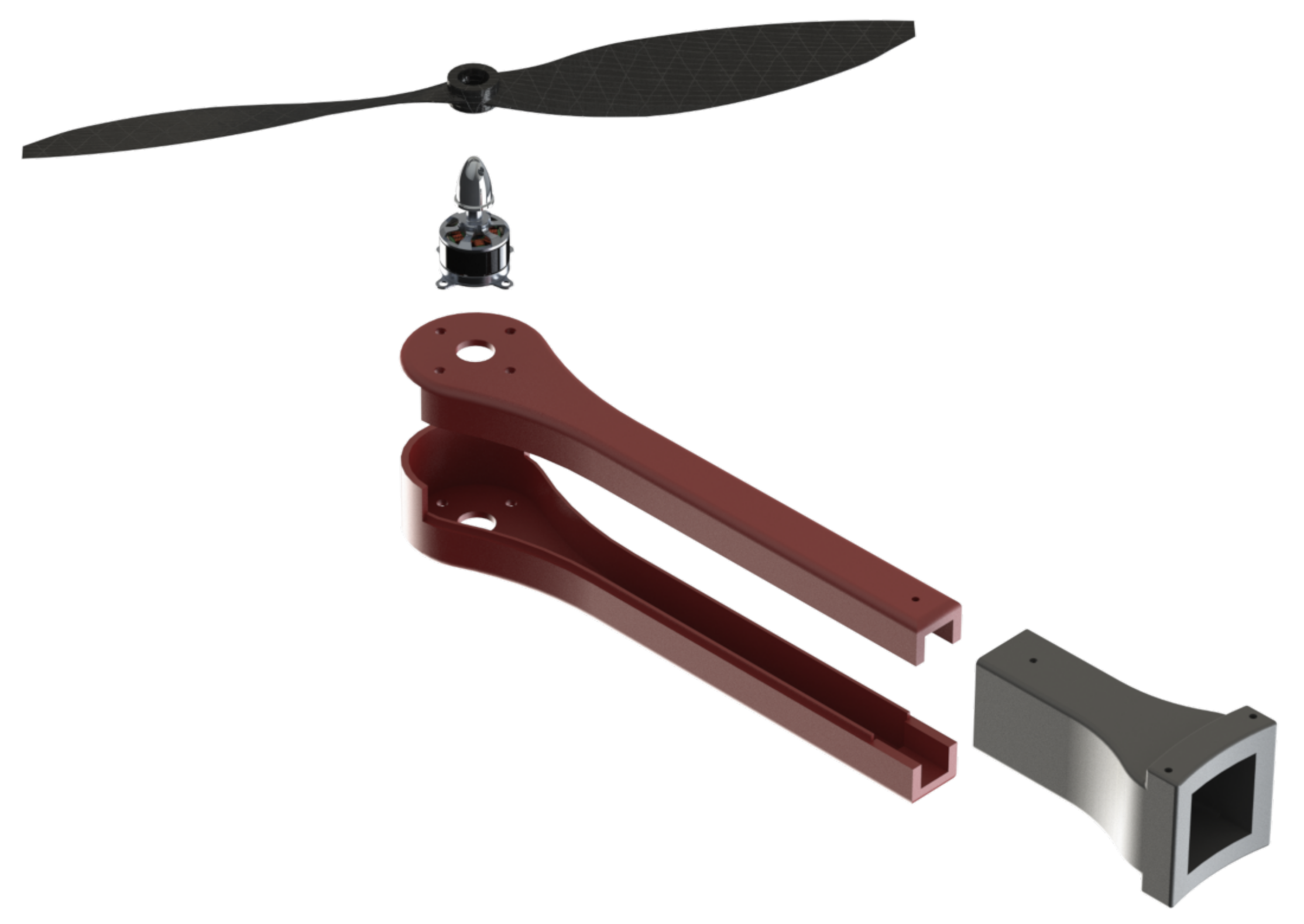
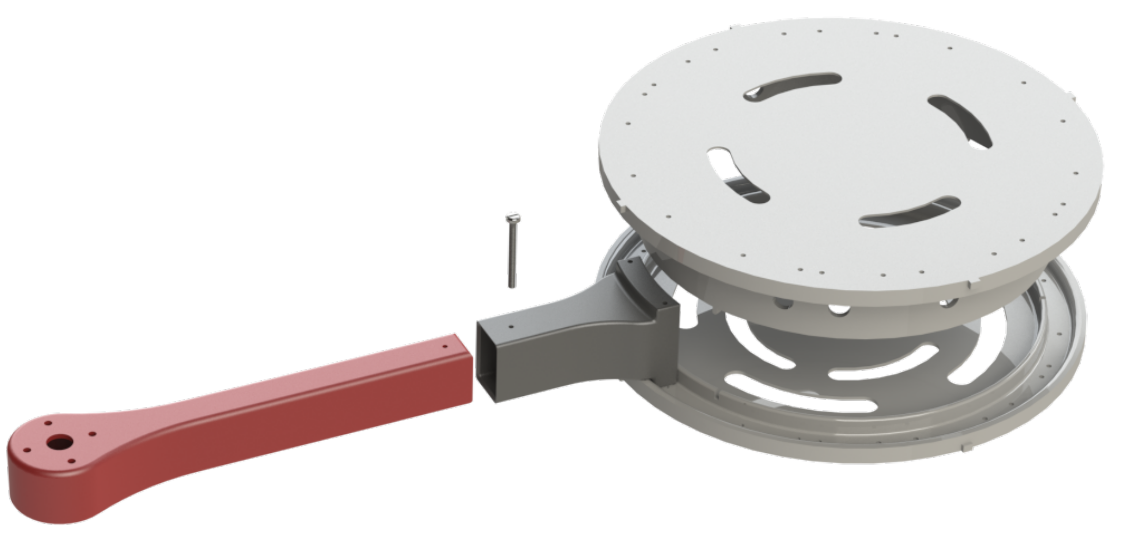
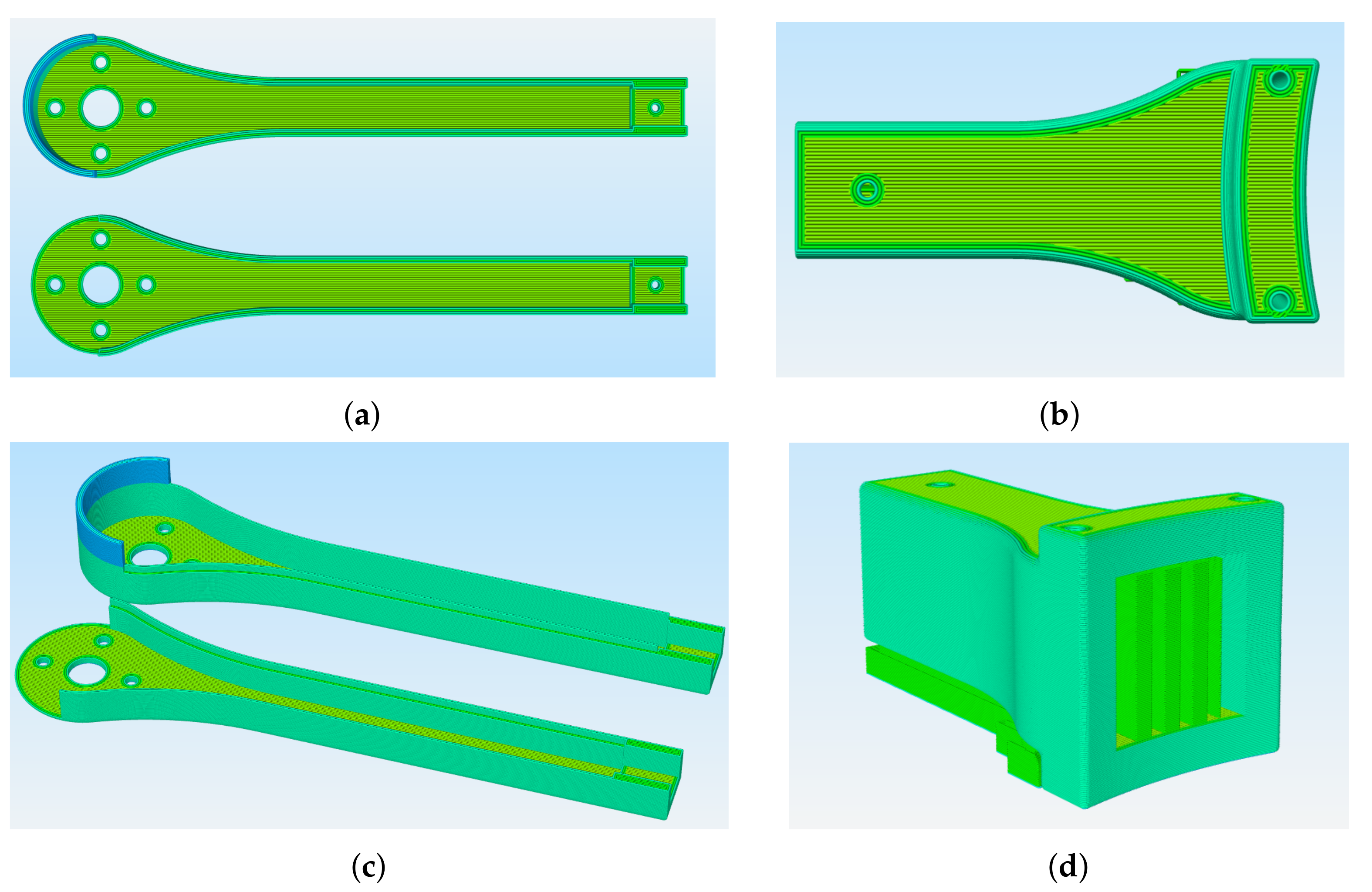
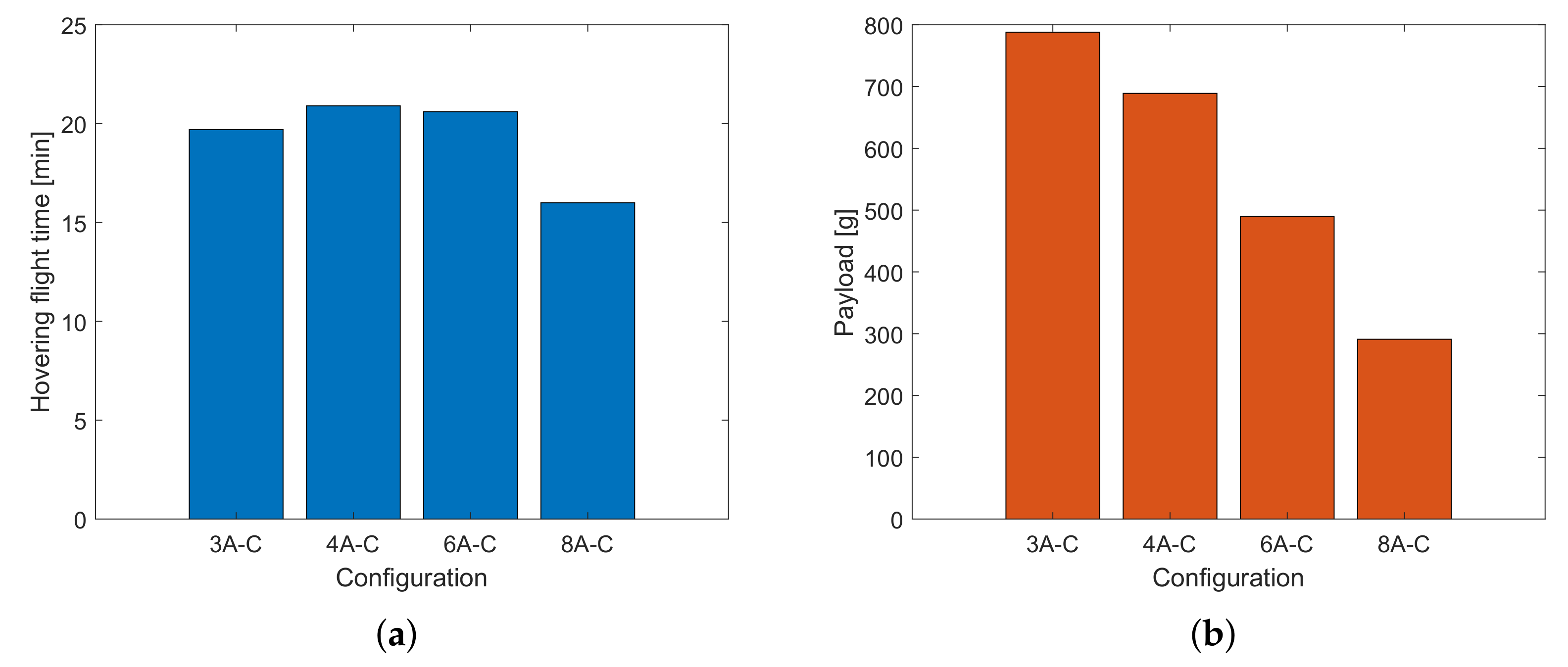
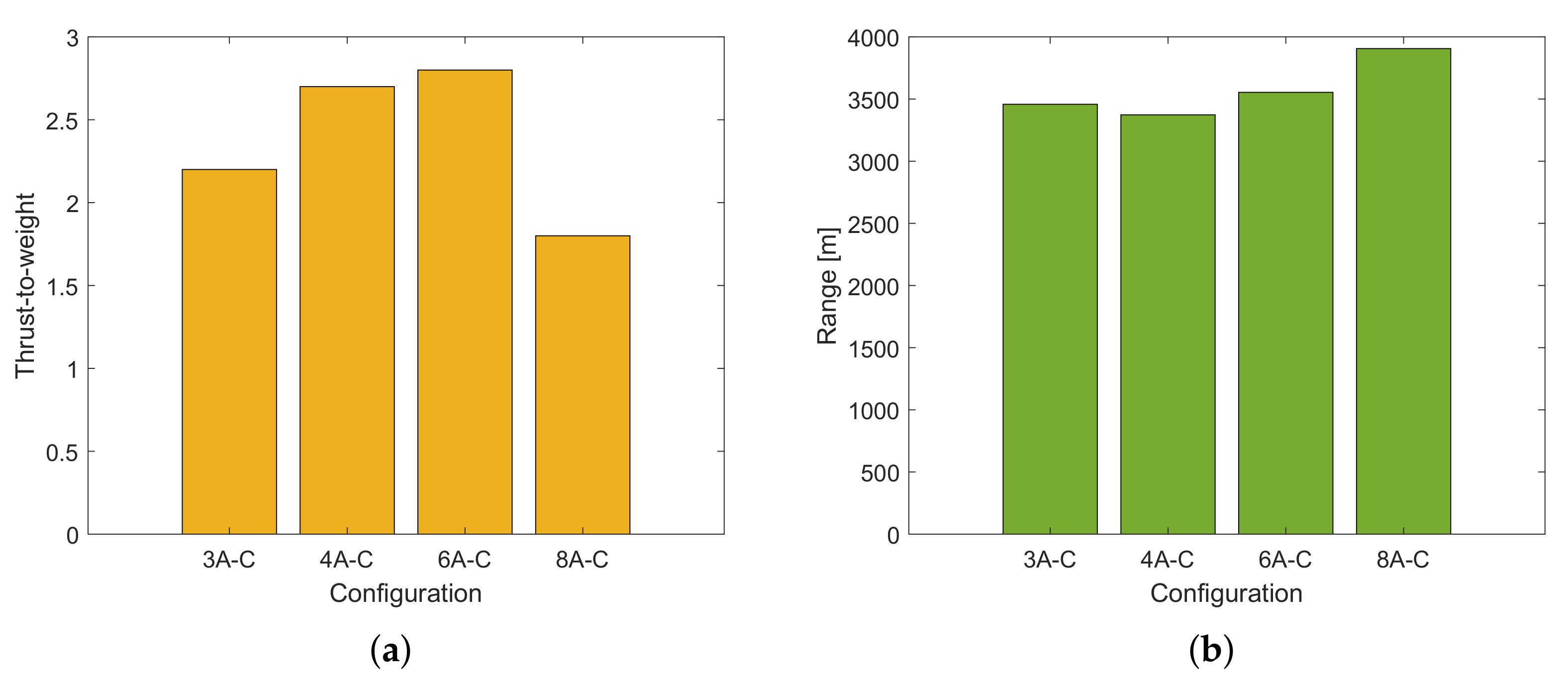
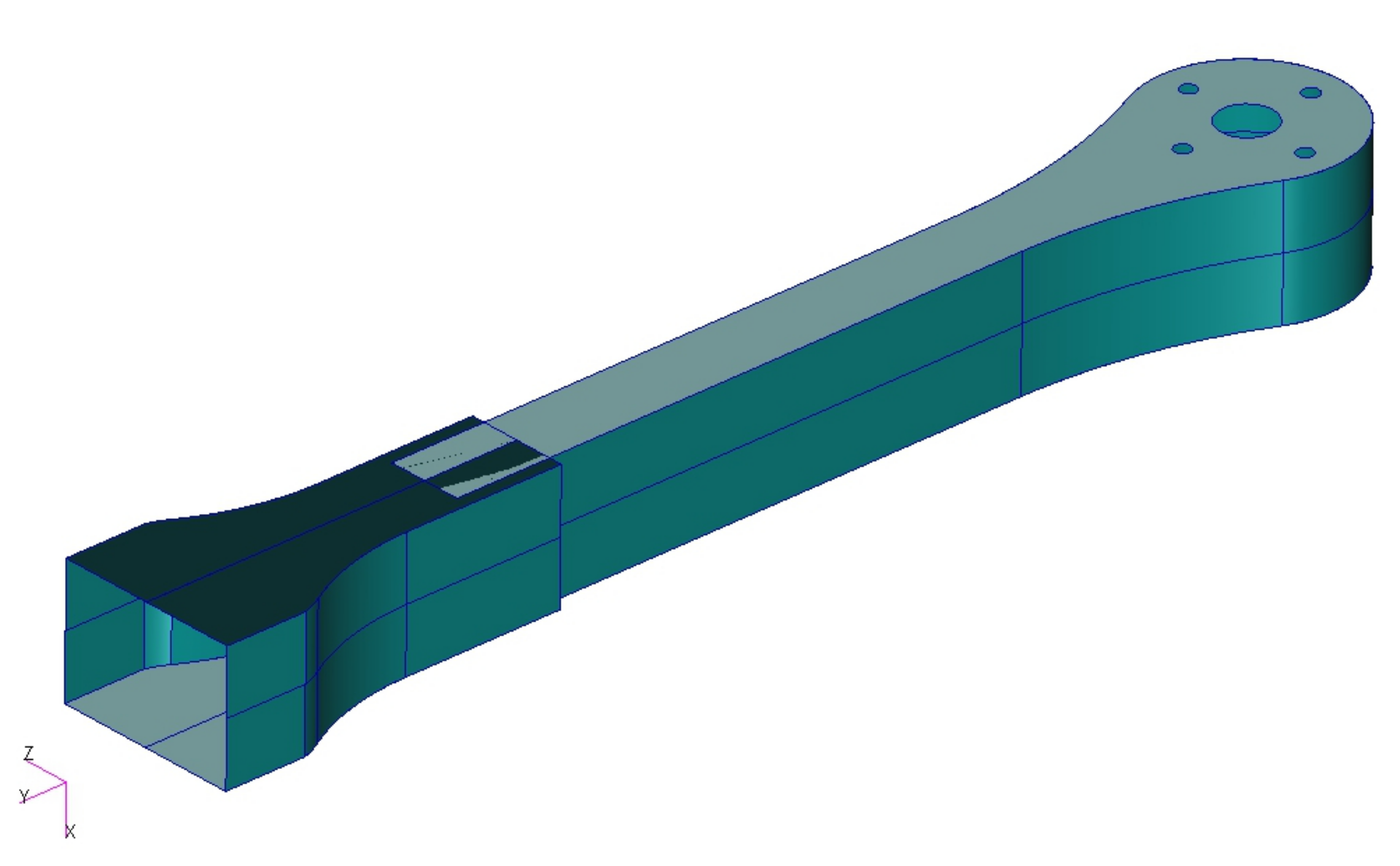
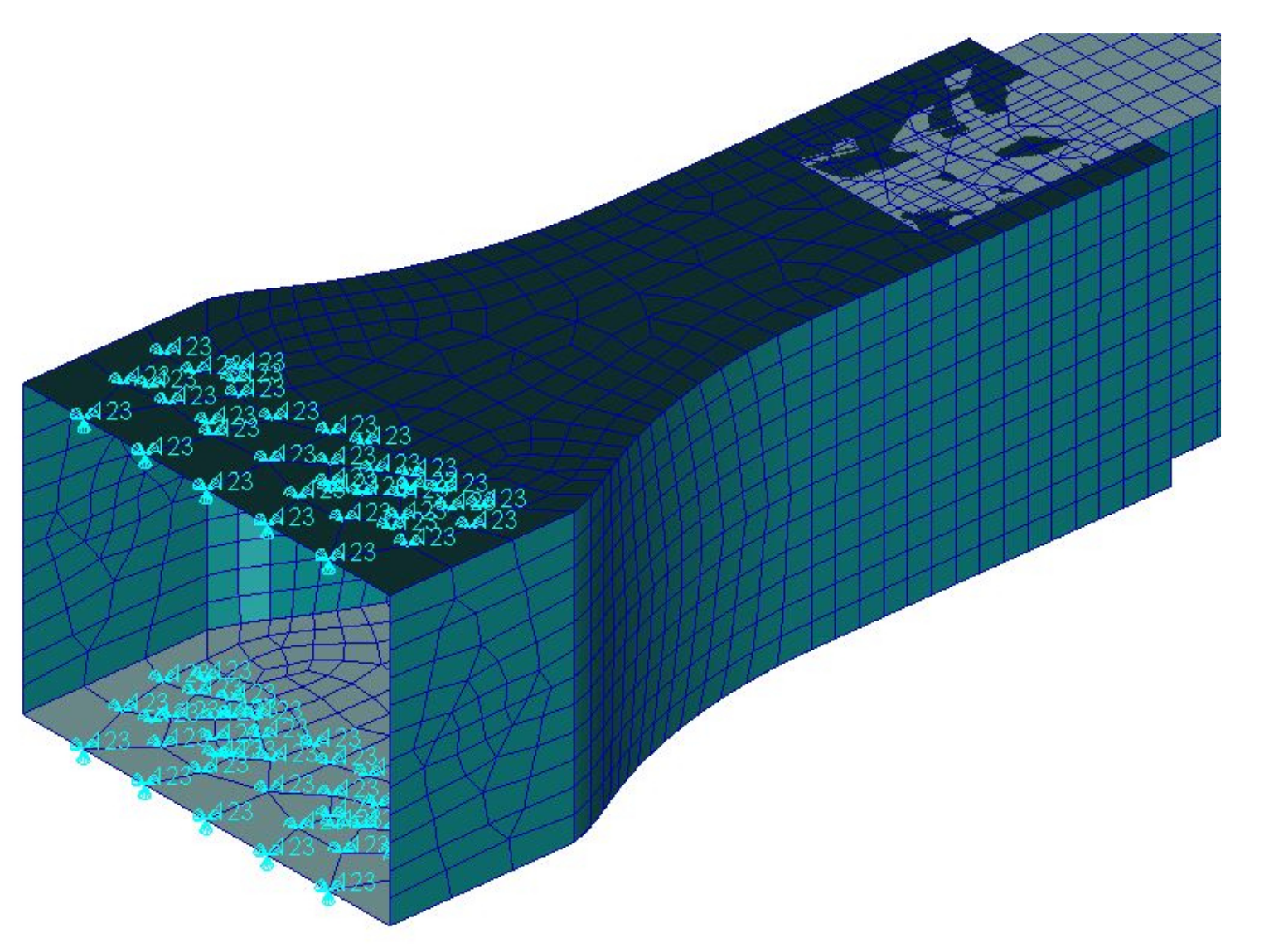
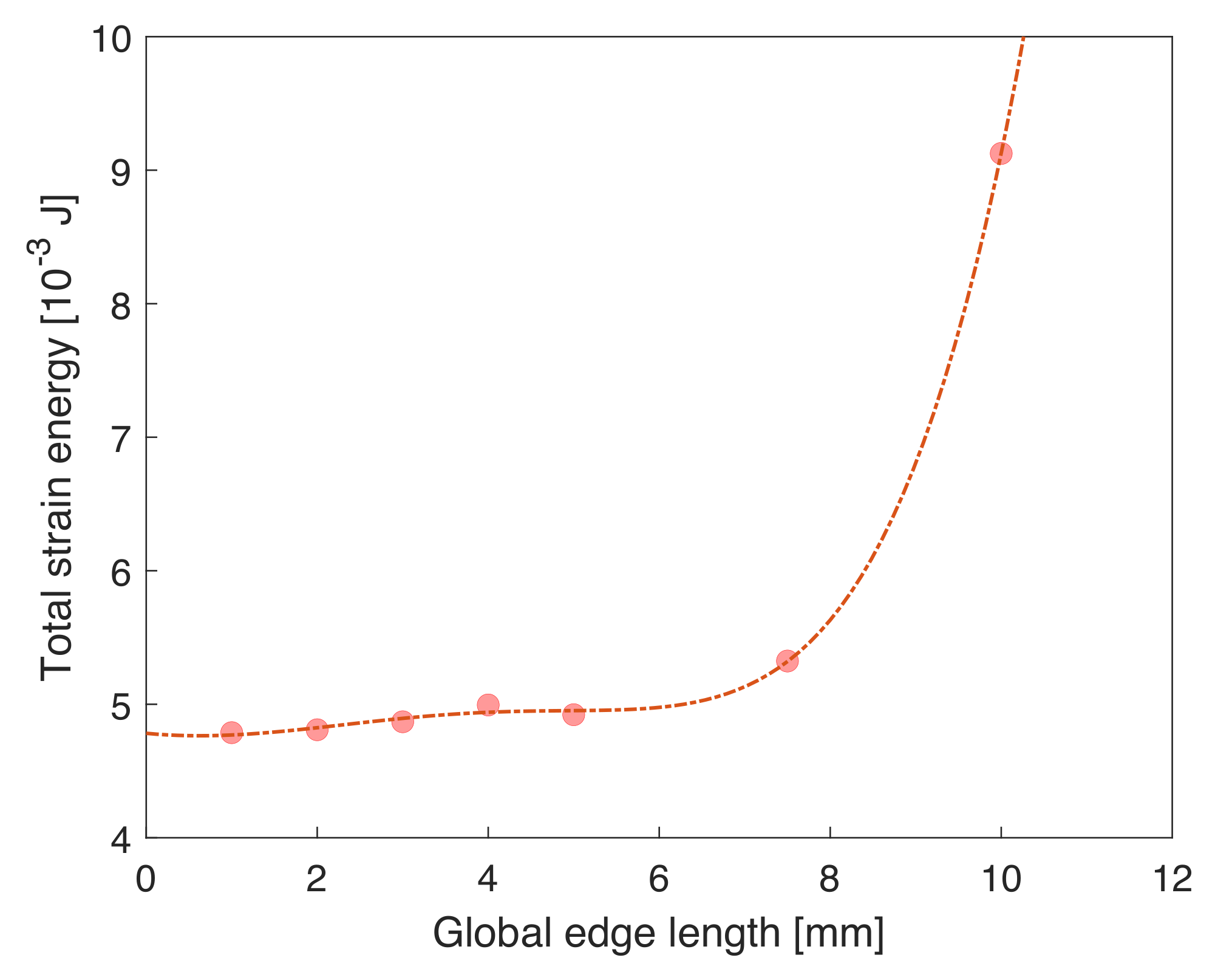
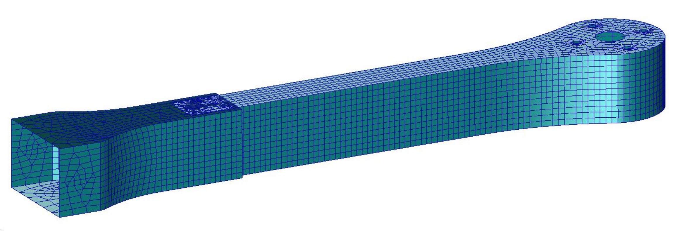
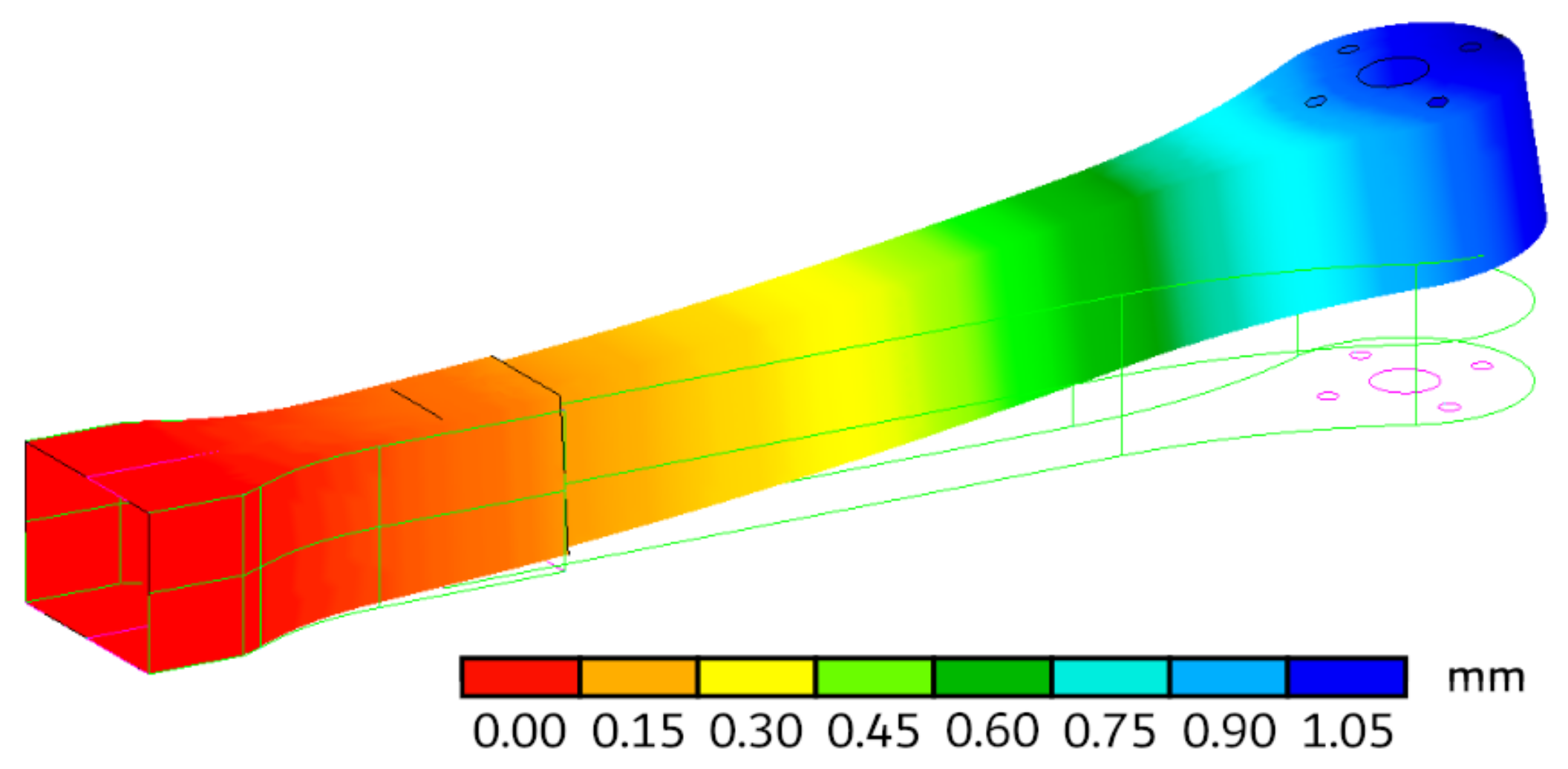
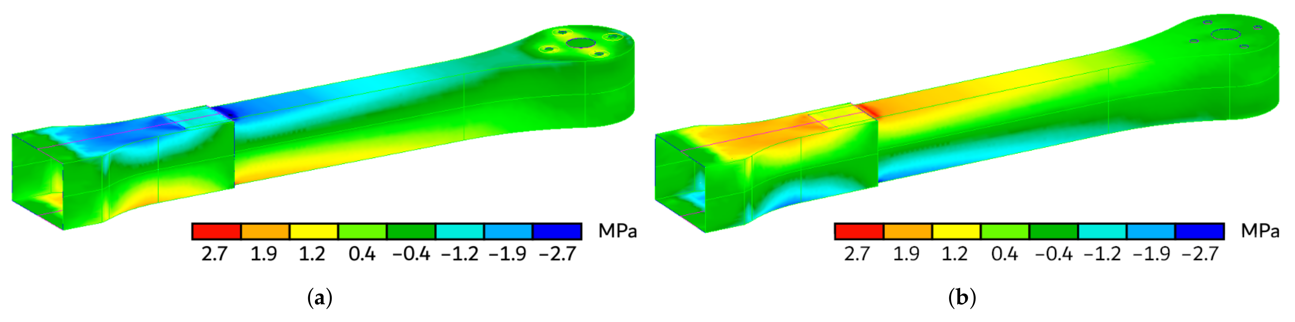
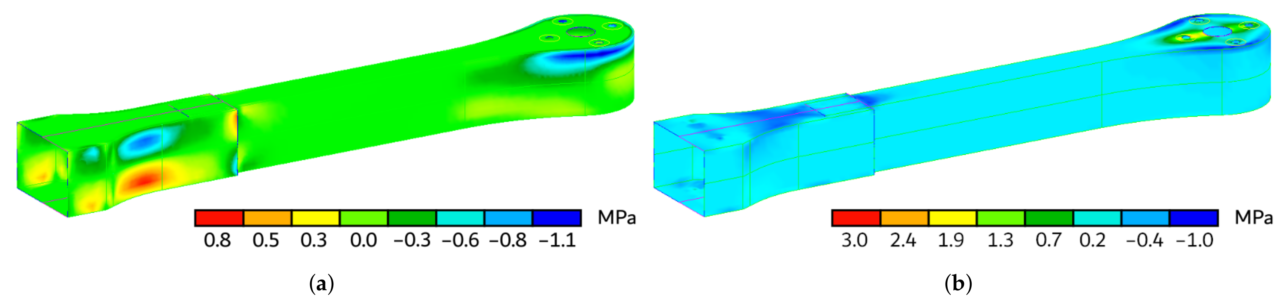
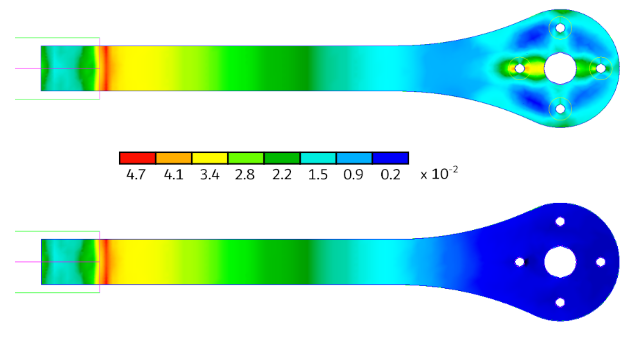
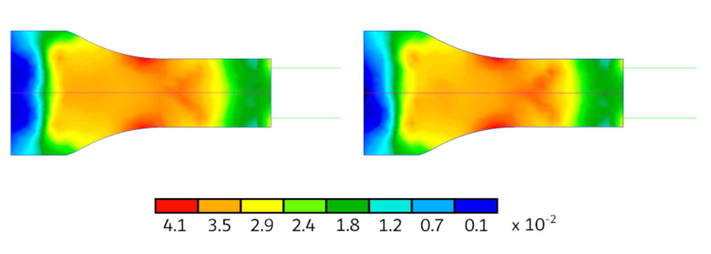
Table 1.
Design of a modular drone: datasheet of the Aeronaut propellers defined per each configuration.
Table 1.
Design of a modular drone: datasheet of the Aeronaut propellers defined per each configuration.
| Setup | Manufacturer | Model | Dia | Pitch | ||
|---|---|---|---|---|---|---|
| S3A-C → | Aeronaut | CamCarbon | ||||
| S4A-C → | ||||||
| S6A-C → | ||||||
| S8A-C → |
Table 2.
Design of a modular drone: optimal motor design ranges per each configuration.
| Motor Wizard | |||||
|---|---|---|---|---|---|
| Input parameters | S3A-C | S4A-C | S6A-C | S8A-C | |
| all-up weight | 2000 g | 2000 g | 2000 g | 2000 g | |
| n of rotors | 3—flat | 4—flat | 6—flat | 8—flat | |
| frame size | 580 mm | 580 mm | 580 mm | 580 mm | |
| battery-rated voltage | V | V | V | V | |
| propeller diameter | |||||
| propeller pitch | |||||
| propeller blades | 2 | 2 | 2 | 2 | |
| Calculated optimal design ranges | |||||
| rpm/voltage [rpm/V] | → | 790–1150 | 680–1000 | 740–1070 | 1090–1580 |
| min. motor power [W] | → | 415–725 | 270–475 | 175–305 | 155–275 |
| min ESC size [A] | → | 45–75 | 30–50 | 20–35 | 20–30 |
Table 3.
Design of a modular drone: datasheet of the NeuMotors model 1230/5Y.
| NeuMotors Model 1230/5Y | |
|---|---|
| rpm/voltage | 987 KV |
| body length | 33 mm |
| weight | 35 g |
| idle current | A @ 10 V |
| max cont. power | 250 W |
| resistance | |
| torque constant | mNm/A |
Table 4.
Design of a modular drone: datasheet of the KISS 18A ESC.
| KISS 18A ESC | |
|---|---|
| input voltage | 2–4 S |
| max continuous amperage | 18 A |
| peak amperage | 30 A |
| width | 12 mm |
| length | 23 mm |
| weight | 2 g |
Table 5.
Comparison between the experimental mechanical properties under the hypothesis of orthotropy and those declared by the manufacturer, assuming that PLA keeps isotropic behavior even after FFF processing.
Table 5.
Comparison between the experimental mechanical properties under the hypothesis of orthotropy and those declared by the manufacturer, assuming that PLA keeps isotropic behavior even after FFF processing.
| PLA Mechanical Properties | |||||||
|---|---|---|---|---|---|---|---|
| Experimental (ORT) | Datasheet (ISO) | ||||||
| 3008 | MPa | [31] | E | 3950 | MPa | [50] | |
| 2876 | MPa | [31] | − | − | − | ||
| 2894 | MPa | [47] | − | − | − | ||
| − | [31] | − | [50] | ||||
| 1227 | MPa | [31] | G | 1182 | MPa | [50] | |
| MPa | [31] | MPa | [50] | ||||
| MPa | [31] | − | − | − | |||
| MPa | [47] | − | − | − | |||
| MPa | [31] | − | − | − | |||
| MPa | [31] | − | − | − | |||
| MPa | [47] | − | − | − | |||
| MPa | [31] | − | − | − | |||
Table 6.
Printing parameters used for specimen production in the characterization campaign.
| 1st layer height | mm | |
| Gen. layer height | mm | |
| Nozzle diameter | mm | |
| Extrusion width | mm | |
| Infill percentage | - | |
| 1st layer extrusion temp. | 190 | C |
| Extrusion temperature | 200 | C |
| Bed temperature | 30 | C |
| Extrusion multiplier | - | |
| Default speed | 3000 | mm/min |
| Retraction distance | 3 | mm |
Table 7.
PoliDrone frame weights assessment.
| Individual Weights | Bill of Materials | ||||
|---|---|---|---|---|---|
| Description | Weight [g] | S3A-C | S4A-C | S6A-C | S8A-C |
| Upper plate | 1 | 1 | 1 | 1 | |
| Bottom plate | 1 | 1 | 1 | 1 | |
| Upper arm element | 3 | 4 | 6 | 8 | |
| Bottom arm element | 3 | 4 | 6 | 8 | |
| Arm support | 3 | 4 | 6 | 8 | |
| Upper dome | 1 | 1 | 1 | 1 | |
| Bottom dome | 1 | 1 | 1 | 1 | |
| Landing gear | 2 | 2 | 2 | 2 | |
| Overall structure weight → | 625 g | 684 g | 804 g | 924 g | |
Table 8.
Turin flight environment data.
| Field Elevation | Air Temperature | Pressure |
|---|---|---|
| 254 m ASL | C | hPa |
Table 9.
Preliminary design of PoliDrone multicopter: frame weights.
| PoliDrone Multicopter—Preliminary Design | |||||
|---|---|---|---|---|---|
| S3A-C | S4A-C | S6A-C | S8A-C | ||
| Weights | Frame | 625 g | 684 g | 804 g | 924 g |
| Drive | 161 g | 201 g | 280 g | 359 g | |
| Battery | 426 g | 426 g | 426 g | 426 g | |
| ALL-UP | 1212 g | 1311 g | 1510 g | 1709 g | |
| Add. Payload | 788 g | 689 g | 490 g | 291 g | |
| Max. Payload | 1212 g | 1756 g | 2102 g | 912 g | |
Table 10.
Preliminary design of PoliDrone multicopter: battery performance estimations. Calculations are based on a 6000 mAh, 11.1 V battery used up to 90%.
Table 10.
Preliminary design of PoliDrone multicopter: battery performance estimations. Calculations are based on a 6000 mAh, 11.1 V battery used up to 90%.
| PoliDrone Multicopter—Preliminary Design | |||||
|---|---|---|---|---|---|
| S3A-C | S4A-C | S6A-C | S8A-C | ||
| Battery | Load | C | C | C | C |
| Voltage | V | V | V | V | |
| Min. flight time | min | min | min | min | |
| Mixed flight time | min | min | min | min | |
| Hovering flight time | min | min | min | min | |
Table 11.
Preliminary design of PoliDrone multicopter: single-motor performance estimations. Calculations are based on a 6000 mAh, 11.1 V battery used up to 90%.
Table 11.
Preliminary design of PoliDrone multicopter: single-motor performance estimations. Calculations are based on a 6000 mAh, 11.1 V battery used up to 90%.
| PoliDrone Multicopter—Preliminary Design | |||||
|---|---|---|---|---|---|
| S3A-C | S4A-C | S6A-C | S8A-C | ||
| @ optimum | Current | A | A | A | A |
| Tension | V | V | V | V | |
| RPM | 9664 | 9617 | 9526 | 9436 | |
| Electrical power | W | W | W | W | |
| Mechanical power | W | W | W | W | |
| Efficiency | % | % | % | % | |
| @ maximum | Current | A | A | A | A |
| Tension | V | V | V | V | |
| RPM | 5740 | 5663 | 6945 | 8894 | |
| Electrical power | W | W | W | ||
| Mechanical power | W | W | |||
| Power to weight | W/kg | W/kg | W/kg | W/kg | |
| Efficiency | % | % | % | % | |
| Est. temperature | 50 | 48 | 32 | 20 | |
| @ hovering | Current | A | A | A | A |
| Tension | V | V | V | V | |
| RPM | 3482 | 3136 | 3760 | 5891 | |
| Electrical power | W | W | W | W | |
| Mechanical power | W | W | W | W | |
| Power to weight | W/kg | W/kg | W/kg | W/kg | |
| Efficiency | % | % | % | % | |
| Est. temperature | 25 | 22 | 18 | 17 | |
Table 12.
Preliminary design of PoliDrone multicopter: motors performance estimations. Calculations are based on a 6000 mAh, 11.1 V battery used up to 90%.
Table 12.
Preliminary design of PoliDrone multicopter: motors performance estimations. Calculations are based on a 6000 mAh, 11.1 V battery used up to 90%.
| PoliDrone Multicopter–Preliminary Design | |||||
|---|---|---|---|---|---|
| S3A-C | S4A-C | S6A-C | S8A-C | ||
| Trust-to-weight | 2.2:1 | 2.7:1 | 2.8:1 | 1.8:1 | |
| @ Hover | Current | A | A | A | A |
| P(in) | W | W | W | W | |
| P(out) | W | W | W | W | |
| Efficiency | % | % | % | % | |
| @ Max | Current | A | A | A | A |
| P(in) | W | W | W | W | |
| P(out) | W | W | W | W | |
| Efficiency | % | % | % | % | |
Table 13.
Preliminary design of PoliDrone multicopter: flight performance estimations. Calculations are based on a 6000 mAh, 11.1 V battery used up to 90%.
Table 13.
Preliminary design of PoliDrone multicopter: flight performance estimations. Calculations are based on a 6000 mAh, 11.1 V battery used up to 90%.
| PoliDrone Multicopter—Preliminary Design | |||||
|---|---|---|---|---|---|
| S3A-C | S4A-C | S6A-C | S8A-C | ||
| Efficiency | Max tilt | 58 | 65 | 65 | 49 |
| Max speed | 47 km/h | 49 km/h | 53 km/h | 50 km/h | |
| Est range | 3458 m | 3373 m | 3554 m | 3906 m | |
| Climb rate | m/s | m/s | m/s | m/s | |
Table 14.
Mesh convergence through gradually smaller element dimensions, expressed in terms of Global Edge Length.
Table 14.
Mesh convergence through gradually smaller element dimensions, expressed in terms of Global Edge Length.
| GEL | Nodes No. | Elements No. | Total Strain Energy | |
|---|---|---|---|---|
| mm | [] | [mm] | ||
| 10 | 3229 | 2741 | ||
| 3489 | 2978 | |||
| 6 | 3618 | 3086 | ||
| 5 | 3801 | 3269 | ||
| 4 | 4324 | 3769 | ||
| 3 | 5277 | 4725 | ||
| 2 | 8215 | 7662 | ||
| 1 | 23,297 | 22,639 |
Publisher’s Note: MDPI stays neutral with regard to jurisdictional claims in published maps and institutional affiliations. |
© 2021 by the authors. Licensee MDPI, Basel, Switzerland. This article is an open access article distributed under the terms and conditions of the Creative Commons Attribution (CC BY) license (https://creativecommons.org/licenses/by/4.0/).
Share and Cite
MDPI and ACS Style
Brischetto, S.; Torre, R. Preliminary Finite Element Analysis and Flight Simulations of a Modular Drone Built through Fused Filament Fabrication. J. Compos. Sci. 2021, 5, 293. https://0-doi-org.brum.beds.ac.uk/10.3390/jcs5110293
AMA Style
Brischetto S, Torre R. Preliminary Finite Element Analysis and Flight Simulations of a Modular Drone Built through Fused Filament Fabrication. Journal of Composites Science. 2021; 5(11):293. https://0-doi-org.brum.beds.ac.uk/10.3390/jcs5110293
Chicago/Turabian StyleBrischetto, Salvatore, and Roberto Torre. 2021. "Preliminary Finite Element Analysis and Flight Simulations of a Modular Drone Built through Fused Filament Fabrication" Journal of Composites Science 5, no. 11: 293. https://0-doi-org.brum.beds.ac.uk/10.3390/jcs5110293