
Mechanical Properties of Compression Moulded Aggregate-Reinforced Thermoplastic Composite Scrap


1
Laboratoire PRISME, MMH, Université Orléans, 45100 Orléans, France
2
Laboratoire de Génie Production, INP-ENIT, Université de Toulouse, 65016 Tarbes, France
*
Author to whom correspondence should be addressed.
J. Compos. Sci. 2021, 5(11), 299; https://0-doi-org.brum.beds.ac.uk/10.3390/jcs5110299
Submission received: 23 September 2021
/
Revised: 21 October 2021
/
Accepted: 29 October 2021
/
Published: 14 November 2021
(This article belongs to the Special Issue Feature Papers in Journal of Composites Science in 2021)
Abstract
:Recycling of thermoplastic composites has drawn a considerable attention in the recent years. However, the main issue with recycled composites is their inferior mechanical properties compared to the virgin ones. In this present study, an alternative route to the traditional mechanical recycling technique of thermoplastic composites has been investigated with the view to increase mechanical properties of the recycled parts. In this regard, the glass/polypropylene laminate offcuts are cut in different grain sizes and processed in bulk form, using compression moulding. Further, the effect of different grain sizes (i.e., different lengths, widths and thicknesses) and other process-related parameters (such as mould coverage) on the tensile properties of recycled aggregate-reinforced composites have been investigated. The tensile properties of all composite samples are tested according to ISO 527-4 test method and the significance of test results is evaluated according to Student’s t-test and Fisher’s F-test respectively. It is observed that the tensile moduli of the recycled panels are close to the equivalent quasi-isotropic continuous fibre-reinforced reference laminate while there is a noteworthy difference in the strengths of the recycled composites. At this stage, the manufactured recycled composites show potential for stiffness-driven application.
1. Introduction
The use of thermoplastic matrices is undergoing a rising trend within the composite industry. This tendency holds to some intrinsic properties that offer some advantages to the thermoplastic matrices over the thermoset ones viz.: no transportation restriction, long-term storage at room temperature, low toxicity during processing, low processing time, ability to weld and their potential of being reprocessed/recycled owing to their thermal reversibility [1,2,3,4,5]. Thermoplastic polymers are often reinforced with long, continuous fibre tapes with fibre volume fraction (Vf) above 40% to enhance their mechanical properties and productivity. At present, the consumption of fibre-reinforced thermoplastic materials is increasing in aerospace and other industries and is expected to grow at the same rate in the coming future [6,7,8]. The increase in the production of thermoplastic composites implies more production scrap in the short-term and more end-of-life parts in the long-term to be dealt with. Alongside, pressures are coming from stringent environmental legislations such as the European Union Waste Framework Directive imposing effective waste management and recycling implementation in the industry [9].
Researchers are currently working towards a circular economy, which is an industrial system aimed at reusing, remanufacturing and recycling of the products at their end-of-life (EOL) stage. Implementation of circular economy can eliminate the production-scrap and end-of-life thermoplastic components [10]. In response to this context, various recycling techniques, namely pyrolysis [11], solvolysis [12] and mechanical processing [13,14], are examined by the research community and are optimised to increase their economic and environmental viability. Some recent studies reported that the mechanical recycling of thermoplastic composite could be the most economically and environmentally viable process if the mechanical properties of these recycled materials are improved further [15,16].
The traditional mechanical recycling of composites involves a shredding step, giving coarse grains followed by a grinding process, giving finer materials which serve afterwards as reinforcement in thermoplastic injection processes [17,18,19]. This recycling route offers the advantage of achieving a high production rate of complex-shaped parts with low scrap generated on the production line. However, the shredding and grinding reduce the effective length of the reinforcement, generally less than 3 mm. Furthermore, the injection process is usually limited to a reinforcement volume fraction lower than 40%, implying virgin material input to decrease the fibre volume fraction as often the initial material to be recycled possesses higher fibre volume fractions [20]. Lower fibre length and fibre volume fraction result in inferior mechanical performances of the recycled composite parts than the virgin ones and limiting the recycled material to low-end applications [21,22]. To overcome the above-mentioned problem, Cradle-to-cradle approaches have been proposed by some authors [23]. De-Bruijn et al. [24] have proposed a solution to retain the maximum mechanical performances of the long fibre-reinforced thermoplastic production scrap consisting of shredding scrap and centimetre-long flakes. They have converted those flakes into a dough by melting and mixing them in a low shear mixer and placed the dough in the mould of a compression moulding machine for a hot press. The above process can achieve better mechanical properties of the recycled composite parts than that of injection-moulded recycled composite parts but are not comparable to its parent composite [24,25].
Over the past few years, extensive research has been conducted on the compression moulding of chopped pre-impregnated tapes in the bulk form [26,27,28,29,30,31,32]. Since the chopped tapes are pre-impregnated, no additional material input is needed in the production line. Hence, the mechanical properties of these so-formed materials depend only on the constitutive parameters and on tape arrangement during manufacturing [30,33]. This fabrication method of thermoplastic composites is a stand-alone process, but it has the potential to process composite manufacturing scraps and end-of-life parts chopped in relatively large grain size to form an aggregate-reinforced composite [29]. The selection of material and the associate manufacturing method give the possibility to have high volume fraction of long-length fibres (generally much higher length than the critical length of fibre), and therefore can overcome the limitations of the traditional mechanical recycling route as identified above.
The present study investigates the applicability of the bulk forming concept to process woven fabric-reinforced thermoplastic composite scrap sheets. That means, instead of having pre-impregnated chopped tapes as input material, the woven fabric-based chopped laminated sheets called grains will be considered. Rasheed et al. [34] have manufactured recycled composite panels after compressing the shredded scrap of woven fabric-reinforced thermoplastic composite sheets in bulk form. It has been observed that the resultant recycled composite retained around 30% tensile modulus and 12% tensile strength to that of their parent composite. However, the authors believe that a recycled composite with improved mechanical properties can be developed by controlling the geometrical properties of the grains and by controlling the fibre-resin distribution and the void content of the recycled composite through optimizing the grain overlap during recycled composite fabrication.
Hence the present work aims to investigate the influence of geometrical parameters of the input grains and initial mould coverage with grains on tensile properties of the recycled composite. The grain size of the present study is chosen in such a way that the grain length should be multiple times longer than the critical fibre length, i.e., 9 mm for glass/PP composites. The grain widths are kept in the range of 5 mm and 10 mm, and three different grain thicknesses, i.e., 1 mm, 0.5 mm and 0.25 mm, are considered for the present study. The initial mould coverage with grains is studied at three levels, i.e., 50%, 75% and 100%, respectively. In addition, this article also highlights some distinctive characteristics for future developments of the studied recycling route.
2. Materials and Methods
2.1. Materials
The initial form of the material on the production line is an E-glass/polypropylene (PP) composite sheet (Figure 1a) with a Vf of 47%, within which the reinforcement is in the form of a balanced 2 × 2 twill weave fabric. The grade of PP used is a commercial grade PP (PPC 13442) produced by Total petrochemical. The tensile modulus, strength and strain of this PP grade are 1.6 GPa, 30 MPa and 5% respectively. The initial composite sheet can be composed of one or multiple elementary plies having all the same orientation. The composite sheets are elaborated by the manufacturer by using the film-stacking process. Two different areal fabric weights, 600 g/m² and 300 g/m² are considered, yielding to an elementary ply thickness of 0.5 mm and 0.25 mm respectively. Offcuts of the initial laminate are taken as the production scrap (Figure 1b). Then for the purpose of this study, the grains of different sizes are cut from the production scrap (Figure 1c). The variety of grain sizes and thickness assessed in this study are summarised in Table 1 while, the irregular shaped grains which are generated during the cutting process are not considered. The grains are then used in bulk to fill the mould in a random distribution (Figure 1d) to manufacture the aggregate-reinforced composite panels (Figure 1e).
2.2. Panel Manufacturing
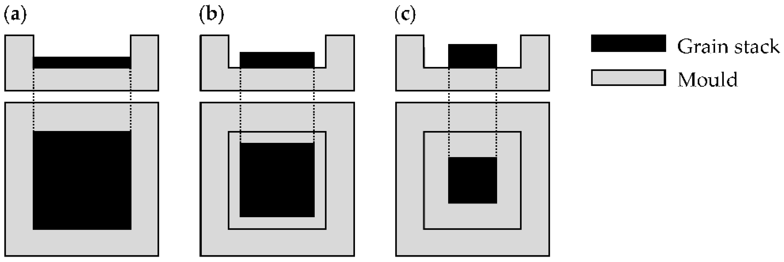
A 300 mm by 300 mm shear-edge compression mould was used to manufacture composite panels of different configurations. The aggregate-reinforced composite panels are manufactured by filling the mould with grains distributed randomly over the mould surface either in a 100%, 75% or 50% mould coverage as shown in Figure 2. The location pattern of the 75% and the 50% mould coverage is centred which signifies that under the consolidation pressure the material will flow in all directions until the mould boundaries are reached. Beside the aggregate-reinforced composites, a quasi-isotropic (QI) [0°/±45°/90°]s continuous fibre-reinforced panel is also manufactured using the composite sheets to serve as a reference sample.
Once the mould is filled with grains, it is closed carefully and is subjected to a heat ramp of 5 °C/min until a temperature of 200 °C is reached. A temperature plateau at 200 °C is then maintained for 15 min to have an isothermal condition in the mould cavity. After 10 min on the temperature plateau, a consolidation pressure (3 bars for QI panels and 50 bars for aggregate-reinforced panels) is applied for the rest of the thermo-compression process. Then, at the end of the temperature plateau, a cooling ramp of 5 °C/min is applied until the mould temperature comes down to 100 °C. After cooling, the panel is unmoulded and then the vertical flash of PP around the contour of the panel is trimmed off. Table 1 summarises the detail of grain sizes used in this study and also the configurations of all manufactured panels. The grain sizes for this study are chosen in such a way that the grain length should be multiple times longer than the critical length (from this length and above the fibre start contributing to composite’s mechanical properties) for the glass/PP composites, viz: ~9 mm [35,36]. Whereas, the choice of grain width is kept in the range of 5 mm and 10 mm just to improve the grain packing in bulk form [37]. Investigating the influence of the mould coverage was sought as it is a key parameter studied for similar materials such as bulk moulding compounds in order to allow material flow, escape of air and filling features like ribs or inserts in engineering applications [38]. The manufactured panel (listed in Table 1) of this study are named in the following manner. The term RA suggests it is a recycled aggregate-based composite, where the numbers followed by the RA term represents the dimensions of the grain used and the mould coverage percentage. For instance, the panel RA250510001003 is made of recycled aggregate having a grain length of 25 mm (defined by 1st two digit), a width of 05 mm (defined by the 2nd and 3rd digits) and a thickness of 1000 micron or 1 mm (defined by the 5th to 8th digits) while the mould cavity is covered 100 percent (defined by the 9th, 10th and 11th digits). The last digit, i.e., number 3 defines the manufactured panel thickness (approximate).
2.3. Tensile Testing and Statistical Analysis
The tensile properties of all composite samples are tested according to ISO 527-4 test method [39]. The test specimens having a dimension of 250 mm (length) by 25 mm (width) are cut from the composite panels using a diamond saw. Then a speckle pattern is created on each specimen in order to follow the displacement field while testing via the digital image correlation (DIC) technique. During testing, the specimens are clamped without tabs and are tested at a rate of 2 mm/min. The average strain field in the gauge section is used to plot the stress–strain curves. The test results i.e., the tensile strength and moduli of all composite samples are analysed using RKWard software Version 0.6.4. While, Fisher’s F-test, p < 0.05 is used to compare the variances and the Student’s t-test, p < 0.05 is used to determine whether the average tensile properties of each independent-samples (listed in Table 1) differ significantly. The statistical analysis is presented in the following format: For the F-test, F4,5 = 0.18, where 4 is the degree of freedom of the reference data series; 5 is the degree of freedom of the second data series and 0.18 is the F-statistic value. Similarly, for t-test the format is t(9) = 0.16; where 9 is the degree of freedom of the combined data series and 0.16 is the t-statistic value. The error bars in the bar graph represent the standard deviation for each data series.
3. Results and Discussions
3.1. Tensile Behaviour and Failure Mechanism
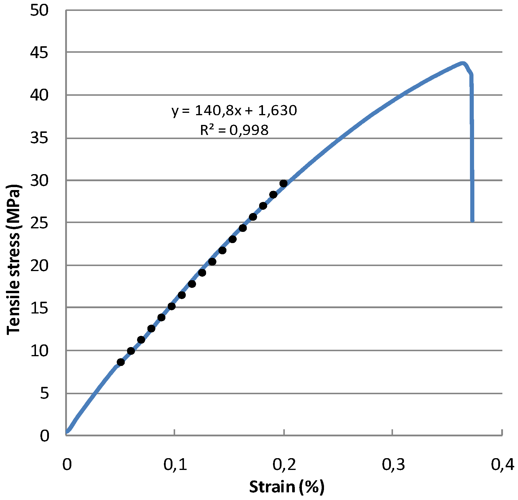
A typical stress–strain curve obtained for the aggregate-reinforced composite specimens is shown in Figure 3. Initially, the stress value of this stress–strain curve rises linearly as a function of strain and then exhibits a non-linear behaviour until the maximum stress value is reached. Once the stress value reaches to a peak, a drastic failure occurs with a major drop in the tensile stress. The tensile strength of the composite specimen is calculated by dividing the peak load with the initial cross-sectional area of the test specimen as shown by Equation (1).
whereas, the tensile modulus is calculated (according to the ISO 527-4 standard test method) by linearising the stress–strain curve in the 0.05–0.25% strain region (the dotted line as shown in Figure 3). The strain values used to draw this stress–strain curve are the averaged axial strain in the strain field measured by DIC. Table 2 summarises the tensile test results of all composite specimen as specified in Table 1.
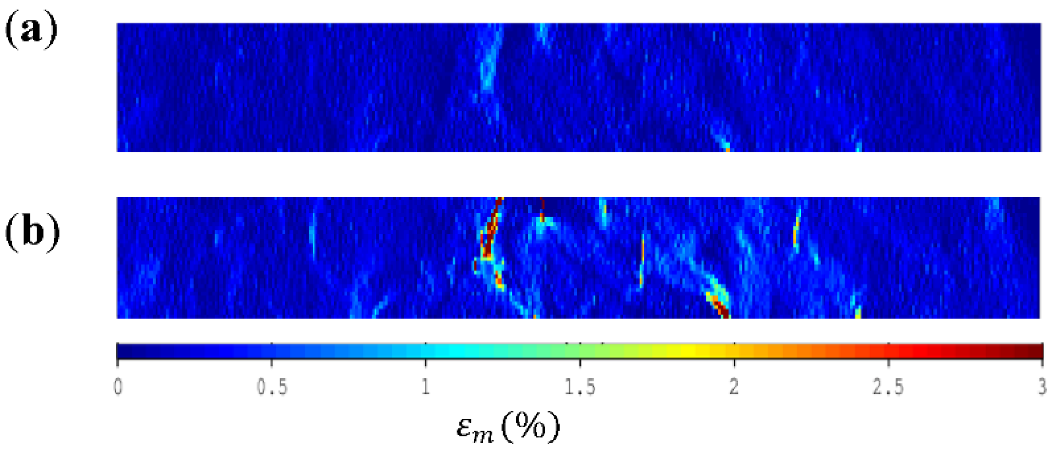
The monitoring of the strain field at different stages of loading reveals many regions where larger strain values are localised, even at low loads (Figure 4a). These high strain regions can be associated to resin-rich regions or regions of low reinforcement which are resulted from the discontinuities of the grains in the specimen. It can also be noted that the high strain regions arise mainly from the edges of the specimen. Similar result is observed by Selezneva et al. [31] while studying the tensile behaviour of chopped-tape-reinforced composites. They have suggested that those weak spots along the specimen edges are due to the shorter length of the grains along the edges as a result of the cutting of the specimen. Zolfagharian et al. [40] have observed that notches in 3D-printed thermoplastic components causes stress concentration which leads to crack initiation and ultimately to the failure of the component. During testing, the high strain regions continue to increase throughout the specimen (Figure 4b) as a function of increasing tensile stress and serve as weak spots until the weakest of them causes the final failure to the specimen. Figure 5 exhibits the fracture faces of a tensile tested specimen which reveals that the fracture path propagated throughout the specimen while avoiding the surrounding grains through delamination in the matrix. This fracture path could be attributed to stress concentrations at the vicinity of the grains as a result of material heterogeneity. The fracture faces show no fibre breakage which indicates that the failure is exclusively dominated by the matrix.
3.2. Assessment of the In-Plane Mechanical Behaviour of the Recycled Panels
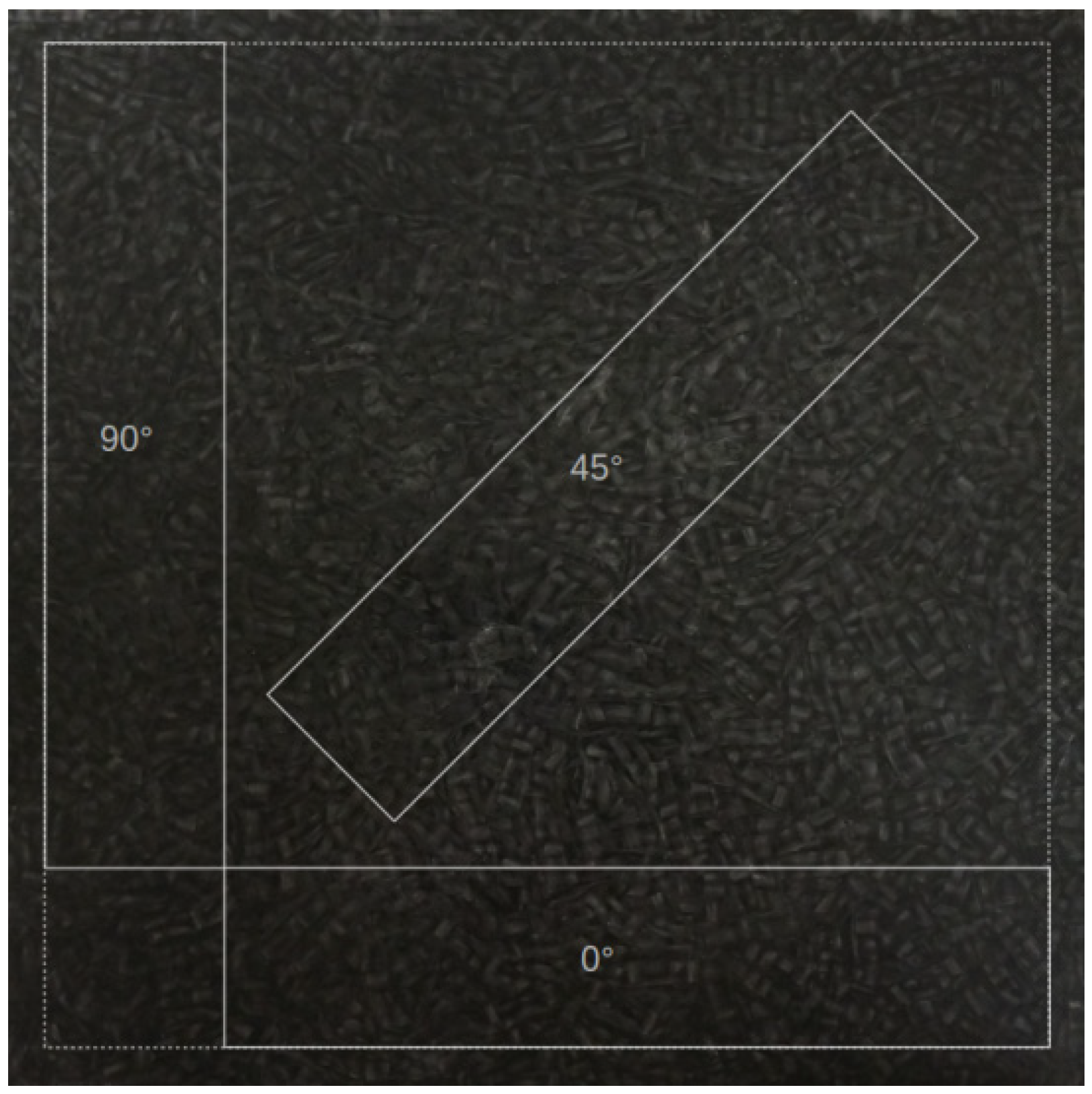
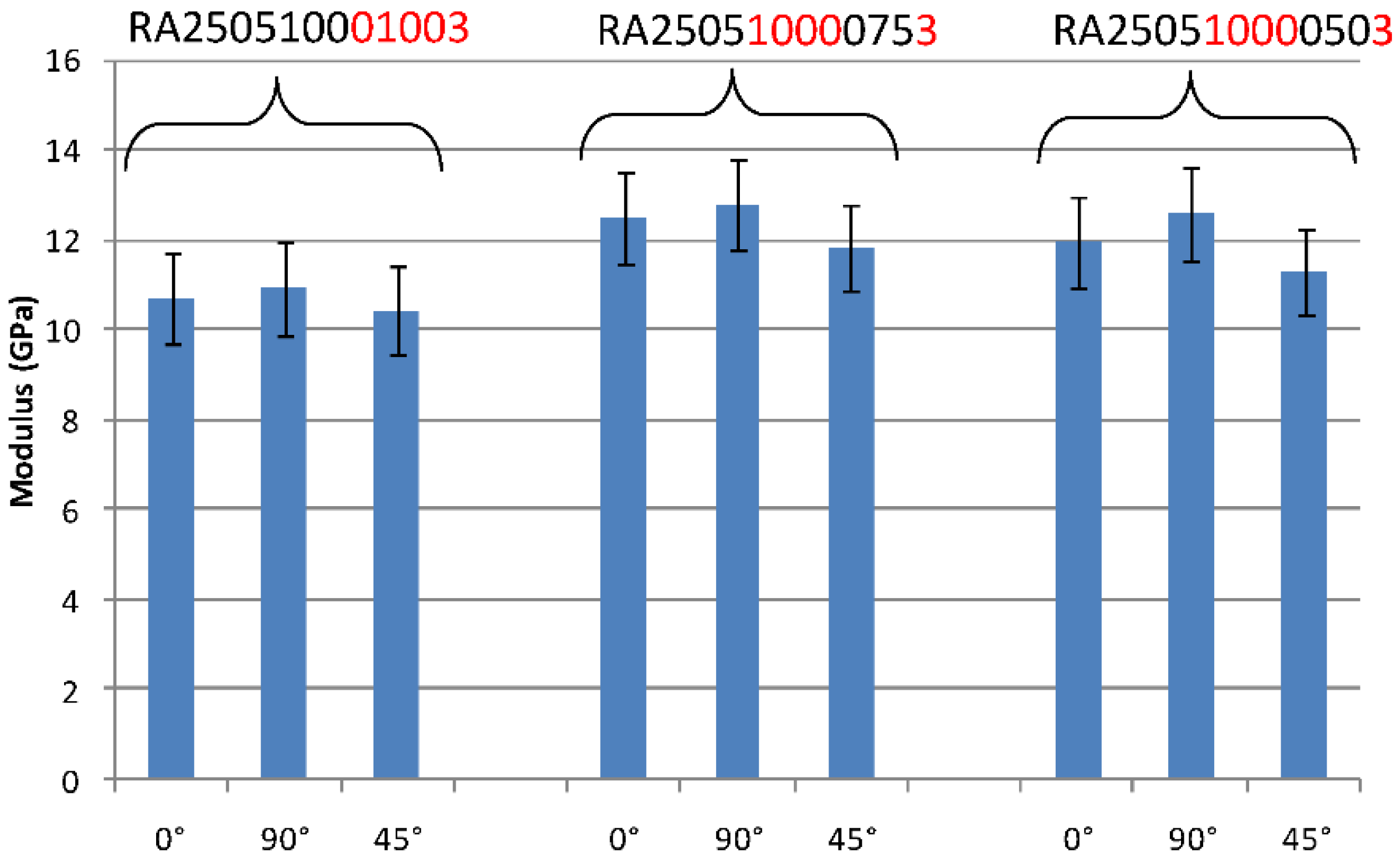
Prior to studying the influence of different grain geometries on the aggregate-reinforced composite properties, an assessment on their quasi-isotropic in-plane behaviour is carried out. In order to achieve a random grain orientation in the composite structure, the grains are shuffled multiple times by hand prior to the mould filling operation. Further, to understand the effectiveness of the above-mentioned mixing operation in yielding quasi-isotropic in-plane behaviour, the tensile tests specimens are cut at 0°, 90° and 45° angle from the composite panel as shown in Figure 6. The tensile tests are performed on the RA250510001003, RA250510000753 and RA25051000503 panels to consider the different mould coverage levels. Figure 7 shows the tensile modulus obtained for each orientation within the respective panels. The standard deviations are lower than 20%. This is relatively low if one considers the fact that the recycled material was obtain from multiple elementary grains. In case of RA250510001003 panel, the ratios of the average modulus in the 90° orientation over the 0° orientation (Mod 90°/Mod 0°) and the average modulus in the 45° orientation over the 0° orientation (Mod 45°/Mod 0°) are respectively 1.02 and 0.97. The associated Student’s t-test comparing the tensile modulus of the specimen cut at 90° and 45° angle with the specimen cut at 0° angle are respectively t(4) = 0.18, p > 0.05 and t(4) = 0.30, p > 0.05. Which means there are no significant difference in the tensile modulus of the specimen cut from RA255100 panel at different angles.
In case of RA250510000753 panel, the 75% mould coverage in a centred pattern implies an axisymmetric macroscopic flow of the grains during compression until the mould boundaries are reached. As a result, the grains tend to align themselves with the mould boundaries as the mould boundaries are approached. For the RA250510000753 panel, the ratios of Mod 90°/Mod 0°and Mod 45°/Mod 0° are respectively 1.02 and 0.95. The associated Student’s t-test comparing the tensile modulus of the specimen cut at 90° and 45° angle with the specimen cut at 0° angle are respectively t(4) = 0.18, p > 0.05 and t(4) = 0.57, p > 0.05 which signifies there is no significant difference. A similar result is obtained in case of RA250510000503 panel, 50% mould coverage in a centred pattern. The ratios of Mod 90°/Mod 0°and Mod 45°/Mod 0° in case of RA25051000050 panel are respectively 1.05 and 0.95. The associated Student’s t-test comparing the tensile modulus of the specimen cut at 90° and 45° angle to the 0° angle are t(4) = 0.53, p > 0.05 and t(4) = 1.09, p > 0.05, signifies no significant difference in the sample compared.
With regard to the previous results, it is inferred that the manufactured aggregate-reinforced composites exhibit quasi-isotropic in-plane material behaviour at the macroscopic scale. The grains maintain a random distributed orientation within the panels even when a charge ratio of 75% or 50% in a centred pattern is considered. This also points out that the bi-directional reinforcement within the grains tends to minimise the orientation effect on the in-plane properties when randomly distributed [34].
3.3. Influence of Grain’s Width and Length
The comparison of RA251010001003 and RA250510001003 panels gives an insight about the influence of the grain’s width on the tensile properties of aggregate-reinforced composite. The range of grain’s width are preselected which are 10 mm and 5 mm for RA251010001003 and RA250510001003 panels respectively. The tensile properties of both RA251010001003 and RA250510001003 panels are reported in Table 2. The literature suggests that the thinner grains provide better aerial coverage and packing in the mould [41]. However, the influence of grain thickness on the tensile strengths of RA251010001003 and RA250510001003 panels is insignificant which are 27.63 MPa and 26.97 MPa respectively, t(15) = 0.19, p > 0.05. Considering the F-test, F7,8 = 0.28, p > 0.05, no significant difference is found between the variances, but a tendency can be pointed out as p < 0.1. This tendency signifies that the variance of the tensile strength decreases as the width of the rectangular grain reduces from 10 mm to 5 mm. This low variability in tensile strength of RA250510001003 panel could be a result of a lower proportion of resin-rich regions as a result of better grain packing. In case of tensile moduli of RA251010001003 and RA250510001003 panels, no tendency or significant differences are observed, t(16) = 1.19, p > 0.05 and the associated variance is F8,8 = 1.17, p > 0.05. Hence, it can be concluded that within the selected range of grain width, this geometrical factor does not have an influence on the tensile modulus of the aggregate-reinforced composite.
The comparison between RA251010001003 and RA501010001003 panels gives an insight about the influence of grain’s length on the tensile behaviour of the aggregate-reinforced composites. A significant increase in the average tensile modulus i.e., from 10.09 GPa to 12.61 GPa; with t-test, t(16) = 5.92, p < 0.05 is observed when the grain length in the respective composite sample increases from 25 mm (RA251010001003 panel) to 50 mm (RA501010001003 panel). This can be explained by the fact that longer grains are more likely to have an in-plane orientation in the aggregate-reinforced composite than the shorter grains and therefore provide a better contribution to the in-plane modulus [31].
Like tensile modulus, an increase in average tensile strength as a function of increasing grain length is observed with the t-test, t(14) = 2.32, p < 0.05. This increase in average tensile strength can be related to a higher potential of overlap between the grains at higher lengths which enhances their ability to withstand crack propagation [31,34]. However, this increase in strength is also accompanied by an increase in dispersion of the strength as the grain length is doubled, F7,7 = 0.07, p < 0.1. This tendency can be somehow linked to an increased heterogeneity in the panel similar to that observed on chopped-tape composites [31]. After analysing the tensile properties (strength and modulus) and the degree of scattering in tensile properties of various aggregate-reinforced composite samples, the size of 25 mm × 5 mm rectangular grain is considered as a standard geometrical size for the evaluation of the other parameters presented in the following sections.
3.4. Effect of Mould Coverage
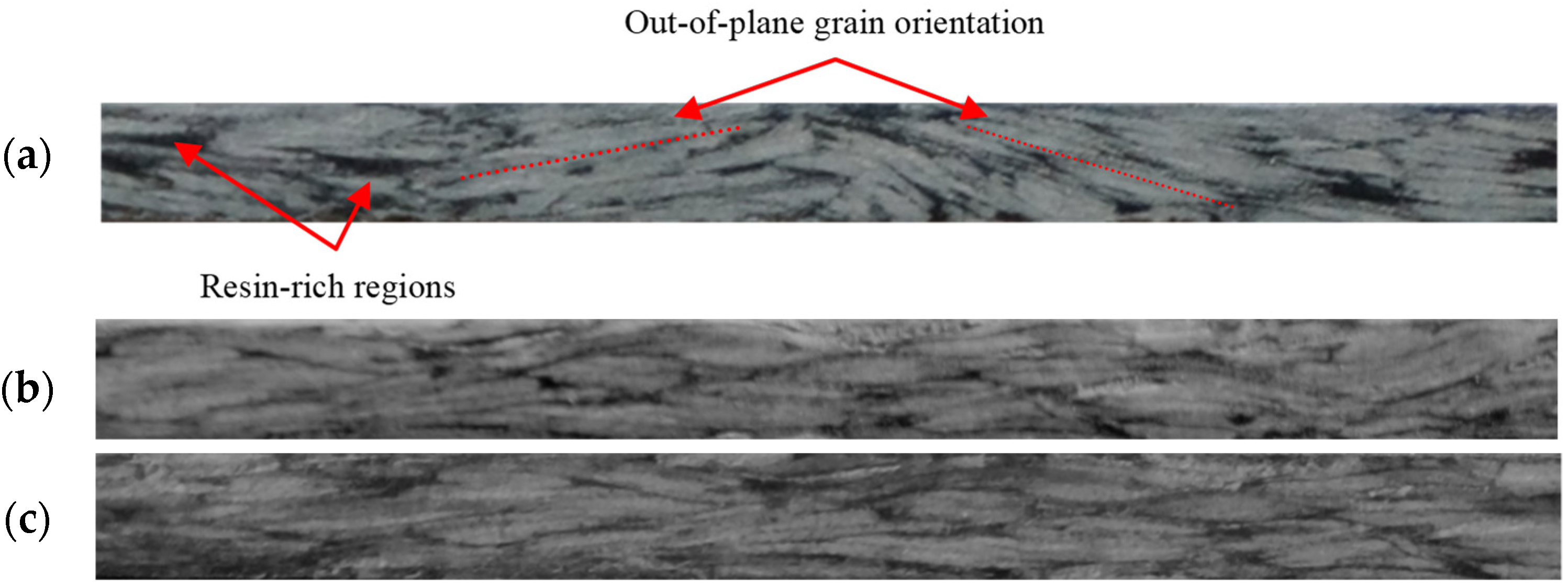
The effect of fractional mould coverage (with grain’s) on the tensile properties of aggregate-reinforced composite is evaluated by analysing the results obtained for RA250510001003, RA250510000753 and RA250510000503 panels having a mould coverage of 100%, 75% and 50% respectively. The location pattern of the 75% and the 50% mould coverage is centred which induces a macroscopic squeeze flow during the consolidation phase of the process cycle where the molten bulk material flows axisymmetrically until the mould walls are reached. During this macroscopic flow, the grains slide over one and another and the material undergoes a mesoscopic flow as well; resulting in the deformation and shear in-between the grains [30]. This mesoscopic flow tends to reduce the resin-rich regions at the grains’ tips and enhances the in-plane orientation of the grains. As a consequence, an increase in tensile strength and modulus is expected in this case. The comparison of the tensile properties between the RA250510001003 and the RA250510000753 panel shows indeed a significant increase both in the tensile strength (t(16) = 4.47, p < 0.05) from 26.97 MPa to 35.00 MPa respectively and tensile modulus (t(16) = 2.79, p < 0.05) from 10.68 GPa to 12.37 GPa respectively. A similar trend i.e., an increase in tensile strength from 26,97 MPa to 46.13 MPa and an increase in tensile modulus from 10.68 GPa to 11.95 GPa as a function of low mould coverage is observed when RA250510001003 and RA250510000503 panels are compared. This confirms the above described effects of the flow mechanism due to the mould coverage on the tensile properties. As inferred, lowering of mould coverage is beneficial to the reduction of resin-rich zones correlates with the observation of the panel cross-sections provided in Figure 8. The specimen from the RA250510001003 panel (Figure 8a) exhibits comparatively more out-of-plane grain orientation and resin-rich regions than that of RA250510000753 panel (Figure 8b) and RA250510000503 panel (Figure 8c). The mould coverage level can therefore be used as an adjustable process parameter to favour in-plane mechanical properties.
3.5. Effect of Grain and Elementary Ply Thickness
The comparisons between RA250510000753, RA250505000753 and RA250502500753 panels are made to assess the effect of grain’s and ply’s thickness on their tensile properties. The grain thickness is the thickness of the initial composite sheet scrap and the ply thickness is the thickness of the elementary ply constituting the initial composite sheet scrap. As stated in Table 1, the grains in the RA250510000753 panel are 1-mm thick and consist of two layers of 0.5-mm thick elementary plies. In RA250505000753 panel, the grains are 0.5-mm thick and consist of 0.5 mm single elementary ply. Whereas, the grains in the RA250502500753 panel are 0.25-mm thick and consist of 0.25 mm single elementary ply. Existing studies on chopped-tape and discontinuous staggered inclusions reinforced composites showed that the strength of these type of composites is toughness-based [42,43,44]. A simplified expression of the strength, σc, is given by the toughness-based criterion in (Equation (2)) where Ec is the composite’s modulus, Gc the mode II interlaminar fracture toughness, H the specimen’s thickness and h an initial damage size [43].
In this section, Ec, Gc and H are assumed to be of the same order of magnitude for all three panels. As a consequence, the investigation will point out whether the initial damage size h is related to the grains’ thickness or the elementary ply’s thickness constituting the grain. The comparison between the RA250510000753 panel and the RA250505000753 panel highlights the effect of the grain’s thickness since the elementary ply thickness is identical in both panels. No difference in the average tensile modulus is observed (t(16) = 1.68, p > 0.05), when the tensile properties of the above-mentioned panels are compared. However, a significant difference in their tensile strength (t(18) = 5.18, p < 0.05) i.e., an increment from 35.00 MPa for RA250510000753 panel to 52.84 MPa for RA250505000753 panel has been observed. The above observation states that the grain’s thickness is a significant parameter that affects the strength of the aggregate-reinforced composites. It can be inferred that it is more the grains’ thickness rather than the constituting elementary ply’s thickness that influences the initial damage size which in turn influences the composite’s strength.
Nonetheless, since that ultimately the minimum grains’ thickness is that of the elementary ply thickness, operating with offcuts of lower elementary ply thickness will certainly lead to higher tensile strength as well. This is confirmed with the results obtained when comparing the RA250505000753 panel with the RA250502500753 panel. Between these two panels, the areal weight of the reinforcement is different, which gives an elementary ply thickness of 0.5 mm and 0.25 mm respectively but the components, i.e., fibre and matrix and the fibre volume fractions are identical. Indeed, in this case, a significant increase in the average tensile strength (t(14) = 2.22, p < 0.05) from 52,84 MPa to 60.66 MPa is observed between the RA250505000753 and the RA250502500753 panel respectively.
This section therefore points out two interesting considerations with regards to aggregate-reinforced composites. Firstly, the grain’s thickness affects the tensile strength in such a way that this method of recycling/reprocessing is further appealing if the grains are cut from single-plies and second that the smaller the elementary ply’s thickness from which the grains are cut from the more effective in terms of tensile strength the aggregate-reinforced composite will be. It should be noted that care should be taken to always specify the grain’s thickness and the elementary ply’s thickness when presenting strengths values for this type of material.
3.6. Effect of Panel’s Thickness
The influence of panel thickness on the aggregate-reinforced composite properties is investigated by comparing the tensile behaviour of RA250510000753 panel with the RA250510000756 panel which has a double panel thickness compared to the previous one. The equation 2 states that thicker panels will lead to higher strength values. Surprisingly, the average tensile strength decreased from 35.00 MPa to 30.83 MPa when the panel thickness is doubled, (t(16) = 2.31, p < 0.05). The fracture faces of RA250510000756 panel is shown in Figure 9, which state that the increase in panel thickness enhances the rotating degree of freedom (the rotation of the grains around its own axis) of the grains in the panels. The out-of-plane orientation of the grains acts as critical flaws in the panel by disrupting continuity and overlap between the contiguous grains in the panel’s thickness. These flaws in the panel ultimately reduce its tensile strength. One way to overcome this flaw would be to increase the width of the grain to a higher value than the ones used in this work. Doing so will reduce the rotating degree of freedom of the grains and will also reduce the tendency of such extreme out-of-plane orientation of the gains. However, the observations in Section 3.3. state that the increase in variability as a function of the increased grain width. Hence, a compromise is to be found in grain size selection in this regard. Another suggestion could be to further reduce the initial mould coverage, which will result in higher flow and probably lead to a better in-plane orientation of the grain as seen in Section 3.4.
In contrast, comparing the average tensile modulus of the two panels showed no significant difference (t(16) = 1.65, p > 0.05). Since the tensile modulus is an averaged volumic material property, this shows that the extreme out-of-plane grain orientations identified are not a general state across the panel but are localised phenomena. Since the strength on the other hand is determined by critical flaws, this can explain the difference observed in strength and not in modulus.
3.7. Overall Assessment
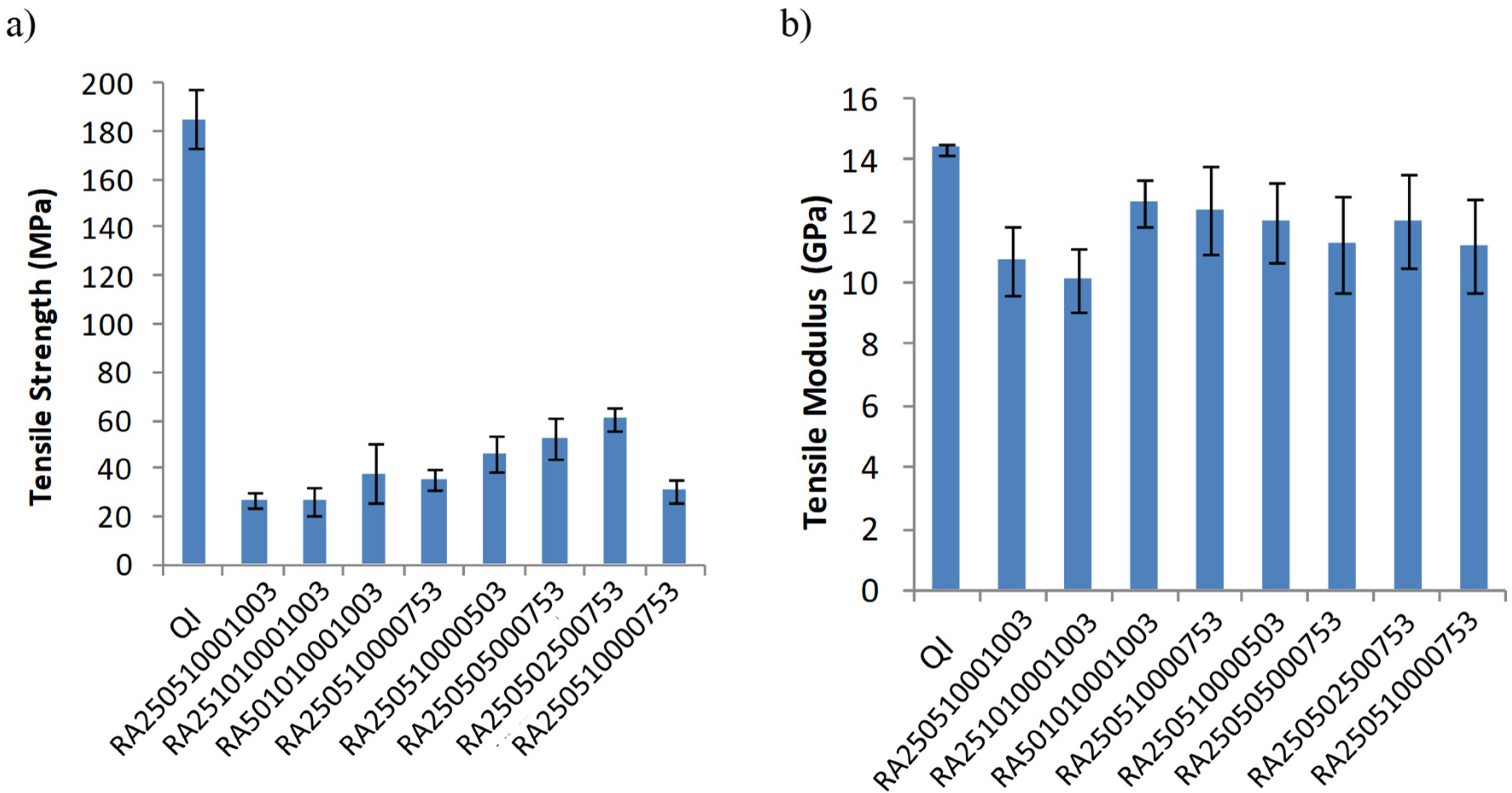
The average tensile strength and modulus of all composite samples are reported in Figure 10a,b, respectively. It is observed that the tensile moduli of the aggregate-reinforced composites are comparable to one of the continuous QI panels with a decrease in the order of 12%. A good proportion of the tensile modulus can therefore be maintained using this recycling/reprocessing method. On the other hand, from the tensile strength point of view, significantly lower values are measured for the aggregate-reinforced composite panels compared to the QI panel as shown in 10a. The configuration of the aggregate-reinforced composite which gave the highest tensile strength, is the RA250502500753 panel with a strength of 60.66 MPa which represents a decrease of −67% compared to the continuous QI panel strength of 185.49 MPa. Such a significant difference in tensile strength can be attributed to the discontinuous nature of the grain within the recycled composites. This probably generates stress concentrations around the edges of the grains and resin-rich regions at the grain’s tip. Both phenomena contribute to the reduction of the tensile strength [44,45]. Furthermore, the important loss in tensile strength can also be attributed to the fact that the failure of the aggregate-reinforced composites is dominated by the matrix as no fibre failure was observed in the fracture faces as noticed in Section 3.1. However, the strength values of the aggregate-reinforced composites remain higher than the strength of neat unreinforced PP, 25 MPa and show potential suitability for stiffness driven and non-critical applications. Future works to improve the strength should however be carried out by studying into more depth the failure mechanisms. Exploring other grain shapes (predefined or random) may also be considered.
4. Conclusions
In the present study, an alternative route to the traditional mechanical recycling technique of thermoplastic composites has been investigated. Production scrap consisting of offcuts of a glass/PP laminates are cut in different grain sizes and processed in bulk form, using compression moulding. The mechanical properties of the aggregate-reinforced panels are characterised through tensile tests to assess the influence of the grain’s geometry and mould filling configurations. A first essential result of this work concerns the quasi-isotropic in-plane behaviour of the recycled panels. This is due to the fact that the grains are randomly distributed during the mould filling operation and regardless of the initial mould coverage (between 50 and 100%) in a centred pattern, the randomness of the grains’ orientation is conserved after the moulding process. This is of particular interest for future designers of recycled composite parts using the process exposed in this work. The results also show that the tensile modulus of the recycled aggregate-reinforced composites is very close to the equivalent QI continuous fibre-reinforced laminate having the same fibre volume fraction. However, a noteworthy decrease in aggregate-reinforced composites strengths is observed. This substantial decrease in strength is attributed to a matrix dominated failure due to resin-rich regions, stress concentrations at the border of the grains, initial damage size in the tensile specimens and out-of-plane grain orientation. The investigation of multiple geometrical parameters showed that the thickness of the grains and that of the elementary ply had a significant effect on the average tensile strength and that length and width had a tendency to influence the variability of the strength as well. These findings suggest that this recycling route is more likely to be convenient for scrap laminates having low thickness values compared to the targeted recycled part thickness. Conversely, high scrap thickness compared to the recycled part thickness could be a limitation of this route as strength decreases significantly. Inducing a macroscopic flow of the grains by varying the initial mould coverage is found to be beneficial to the in-plane tensile properties of the panels. This experimental campaign showed that grain constitution (components, associated mixture fractions and single-ply density) as well as the geometrical parameters of the grains are essential specifications for these types of materials and should be included in every experimental report.
At this stage, the aggregate-reinforced composites show potential for stiffness driven and non-critical applications. Future studies will consider the flow mechanisms involved during moulding and the feasibility of achieving functional features like ribs, flanges and stiffeners usually encountered in compression-moulded parts.
Author Contributions
J.M.: conceptualisation, methodology, writing—original draft preparation, investigation, software. M.B.: validation, formal analysis, writing—review and editing. P.O.: validation, formal analysis, writing—review and editing, project administration, supervision, funding acquisition. All authors have read and agreed to the published version of the manuscript.
Funding
The authors would like to thank the Region Centre, France for their financial support.
Acknowledgments
The authors would like to thank the COGIT Composites for their technical assistance.
Conflicts of Interest
The authors declare no conflict of interest.
References
- Faruk, O.; Bledzki, A.K.; Fink, H.P.; Sain, M. Biocomposites reinforced with natural fibers: 2000–2010. Prog. Polym. Sci. 2012, 37, 1552–1596. [Google Scholar] [CrossRef]
- Munde, Y.S.; Ingle, R.B.; Siva, I. A comprehensive review on the vibration and damping characteristics of vegetable fiber-reinforced composites. J. Reinf. Plast. Compos. 2019, 38, 822–832. [Google Scholar] [CrossRef]
- Bar, M.; Das, A.; Alagirusamy, R. Studies on flax-polypropylene based low-twist hybrid yarns for thermoplastic composite reinforcement. J. Reinf. Plast. Compos. 2017, 36, 818–831. [Google Scholar] [CrossRef]
- Barnett, P.R.; Gilbert, C.L.; Penumadu, D. Repurposed/recycled discontinuous carbon fiber organosheet development and composite properties. Compos. Part C 2021, 4, 100092. [Google Scholar] [CrossRef]
- Yassin, K.; Hojjati, M. Processing of thermoplastic matrix composites through automated fiber placement and tape laying methods A review. J. Thermoplast. Compos. Mater. 2018, 31, 1676–1725. [Google Scholar] [CrossRef]
- Technotes, B.E. Composite Recycling and Disposal: An Environmental R&D Issue. Boeing Environ. Technotes 2003, 8, 1–4. [Google Scholar]
- Khosravani, M.R. Composite materials manufacturing processes. Appl. Mech. Mater. 2012, 110, 1361–1367. [Google Scholar] [CrossRef]
- Alomayri, T.; Shaikh, F.U.A.; Low, I.M. Synthesis and mechanical properties of cotton fabric reinforced geopolymer composites. Compos. Part B Eng. 2014, 60, 36–42. [Google Scholar] [CrossRef] [Green Version]
- Official Journal of the European Community. Directive 2000/53/EC on End-of Life Vehicles; Official Journal of the European Community: Aberdeen, UK, 2000. [Google Scholar]
- Zhang, J.; Chevali, V.S.; Wang, H.; Wang, C.H. Current status of carbon fibre and carbon fibre composites recycling. Compos. Part B 2020, 193, 108053. [Google Scholar] [CrossRef]
- Pickering, S.J. Recycling technologies for thermoset composite materials—current status. Compos. Part A 2006, 37, 1206–1215. [Google Scholar] [CrossRef]
- Pimenta, S.; Pinho, S.T. Recycling carbon fibre reinforced polymers for structural applications: Technology review and market outlook. Waste Manag. 2011, 31, 378–392. [Google Scholar] [CrossRef] [Green Version]
- Beauson, J.; Lilholt, H.; Brøndsted, P. Recycling solid residues recovered from glass fibre-reinforced composites—A review applied to wind turbine blade materials. J. Reinf. Plast. Compos. 2014, 33, 1542–1556. [Google Scholar] [CrossRef]
- Oliveux, G.; Dandy, L.O.; Leeke, G.A. Current status of recycling of fibre reinforced polymers: Review of technologies, reuse and resulting properties. Prog. Mater. Sci. 2015, 72, 61–99. [Google Scholar] [CrossRef] [Green Version]
- Yang, Y.; Boom, R.; Irion, B.; van Heerden, D.J.; Kuiper, P.; de Wit, H. Recycling of composite materials. Chem. Eng. Process. 2012, 51, 53–68. [Google Scholar] [CrossRef]
- Li, X.; Bai, R.; McKechnie, J. Environmental and financial performance of mechanical recycling of carbon fibre reinforced polymers and comparison with conventional disposal routes. J. Clean Prod. 2016, 127, 451–460. [Google Scholar] [CrossRef]
- Vincent, G.A.; de Bruijn, T.A.; Wijskamp, S.; Rasheed, M.I.A.; van Drongelen, M.; Akkerman, R. Shredding and sieving thermoplastic composite scrap: Method development and analyses of the fibre length distributions. Compos. Part B 2019, 176, 107197. [Google Scholar] [CrossRef] [Green Version]
- Chen, J.; Wang, J.; Ni, A. Recycling and reuse of composite materials for wind turbine blades: An overview. J. Reinf. Plast. Compos. 2019, 38, 567–577. [Google Scholar] [CrossRef]
- Schinner, G.; Brandt, J.; Richer, H. Recycling carbon-fiber-reinforced thermoplastic composites. J. Thermoplast. Compos. Mater. 1996, 9, 239–245. [Google Scholar] [CrossRef]
- Otheguy, M.E.; Gibson, A.G.; Findon, E.; Cripps, R.M.; Mendoza, A.O.; Castro, M.A. Recycling of end-of-life Thermoplastic composite boats. Plast. Rubber Compos. 2009, 38, 406–411. [Google Scholar] [CrossRef]
- Vincent, G.; de Bruijn, T.A.; Rasheed, M.I.; Wijskamp, S.; Akkerman, R. Fibre length distribution of shredded thermoplastic composite scrap. In Proceedings of the 21st International Conference on Composite Materials (ICCM/21), Xi’an, China, 20–25 August 2017. [Google Scholar]
- Li, H.; Englund, K. Recycling of carbon fiber-reinforced thermoplastic composite wastes from the aerospace industry. J. Compos. Mater. 2017, 51, 1265–1273. [Google Scholar] [CrossRef]
- Roux, M.; Eguémann, N.; Dransfeld, C.; Thiébaud, F.; Perreux, D. Thermoplastic carbon fibre reinforced polymer recycling with electrodynamical fragmentation: From cradle to cradle. J. Thermoplast. Compos. Mater. 2015, 30, 381–403. [Google Scholar] [CrossRef]
- DeBruijn, T.A.; Vincent, G.A.; VanHattum, F.W.J. Recycling C/PPS laminates into long fibre thermoplastic composites by low shear mixing. In Proceedings of the 21st International Conference in Composite Materials, Xi’an, China, 20–25 August 2017. [Google Scholar]
- Vincent, G.A.; de Bruijn, T.A.; Wijskamp, S.; Rasheed, M.I.; van Drongelen, M.; Akkerman, R. Characterisation and improvement of the quality of mixing of recycled thermoplastic composites. Compos. Part C 2021, 4, 100108. [Google Scholar] [CrossRef]
- Feraboli, P.; Cleveland, T.; Ciccu, M.; Stickler, P.; DeOto, L. Defect and damage analysis of advanced discontinuous carbon/epoxy composite materials. Compos. Part A 2010, 41, 888–901. [Google Scholar] [CrossRef]
- Feraboli, P.; Cleveland, T.; Stickler, P.; Halpin, J. Stochastic laminate analogy for simulating the variability in modulus of discontinuous composite materials. Compos. Part A 2010, 41, 557–570. [Google Scholar] [CrossRef]
- Feraboli, P.; Peitso, E.; Cleveland, T.; Stickler, P.B.; Halpin, J.C. Notched behavior of prepreg-based discontinuous carbon fiber/epoxy systems. Compos. Part A 2009, 40, 289–299. [Google Scholar] [CrossRef]
- Landry, B.; Hubert, P. Experimental study of defect formation during processing of randomly-oriented strand carbon/PEEK composites. Compos. Part A 2015, 77, 301–309. [Google Scholar] [CrossRef]
- Levy, A.; Hubert, P. Interstrand void content evolution in compression moulding of randomly oriented strands (ROS) of thermoplastic composites. Compos. Part A 2015, 70, 121–131. [Google Scholar] [CrossRef]
- Selezneva, M.; Lessard, L. Characterization of mechanical properties of randomly oriented strand thermoplastic composites. J. Compos. Mater. 2016, 50, 2833–2851. [Google Scholar] [CrossRef]
- Selezneva, M.; Roy, S.; Meldrum, S.; Lessard, L.; Yousefpour, A. Modelling of Mechanical Properties of Randomly Oriented Strands Thermoplastic Composites. In Proceedings of the ECCM16–16th European Conference on Composite Materials, Seville, Spain, 22–26 June 2014. [Google Scholar]
- Picher-Martel, G.-P.; Levy, A.; Hubert, P. Compression molding of Carbon/Polyether ether ketone composites: Squeeze flow behavior of unidirectional and randomly oriented strands. Polym. Compos. 2017, 38, 1828–1837. [Google Scholar] [CrossRef]
- Rasheed, M.I.A.; Rietman, B.; Visser, H.A.; Akkerman, R. Experimental Characterisation of Recycled (GLASS/TPU Woven Fabric) Flake Reinforced Thermoplastic Composites. In Proceedings of the 19th International Conference on Composite Materials Iccm, Montreal, QC, Canada, 28 July–2 August 2013; pp. 1–12. [Google Scholar]
- Picher-Martel, G.-P. Compression Moulding of Randomly-Oriented Strand Thermoplastic Composites: A Study of the Flow and Deformation Mechanisms; McGill University: Montréal, QC, Canada, 2015. [Google Scholar]
- Etcheverry, M.; Barbosa, S.E. Glass Fiber Reinforced Polypropylene Mechanical Properties Enhancement by Adhesion Improvement. Materials 2012, 5, 1084–1112. [Google Scholar] [CrossRef] [Green Version]
- Harper, L.T.; Turner, T.A.; Warrior, N.A.; Dahl, J.S.; Rudd, C.D. Characterisation of random carbon fibre composites from a directed fibre preforming process: Analysis of microstructural parameters. Compos. Part A 2006, 37, 2136–2147. [Google Scholar] [CrossRef]
- Evans, A.D.; Qian, C.C.; Turner, T.A.; Harper, L.T.; Warrior, N.A. Flow characteristics of carbon fibre moulding compounds. Compos. Part A 2016, 90, 1–12. [Google Scholar] [CrossRef]
- ISO 527-4:1997; Plastics—Determination of Tensile Properties—Part 4: Test Conditions for Isotropic and Orthotropic Fibre-Reinforced Plastic Composites. Available online: https://www.iso.org/obp/ui/#iso:std:iso:527:-4:ed-1:v1:en (accessed on 15 April 1997).
- Zolfagharian, A.; Khosravani, M.R.; Kaynak, A. Fracture resistance analysis of 3D-printed polymers. Polymers 2020, 12, 302. [Google Scholar] [CrossRef] [Green Version]
- Harper, L.T. Discontinuous Carbon Fibre Composites for Automotive Applications. Doctoral Dissertation, University of Nottingham, Nottingham, UK, 2006. [Google Scholar]
- Ogi, K.; Yamanouchi, M. A Simple Fracture Mechanical Model for Predicting Tensile Strength of an SMC Composite. J. Jpn. Soc. Compos. Mater. 2010, 36, 198–204. [Google Scholar] [CrossRef] [Green Version]
- Pimenta, S.; Robinson, P. An analytical shear-lag model for composites with ‘brick-and-mortar’ architecture considering non-linear matrix response and failure. Compos. Sci. Technol. 2014, 104, 111–124. [Google Scholar] [CrossRef]
- Taketa, I.; Okabe, T.; Kitano, A. A new compression-molding approach using unidirectionally arrayed chopped strands. Compos. Part A 2008, 39, 1884–1890. [Google Scholar] [CrossRef]
- Taketa, I.; Sato, N.; Kitano, A.; Nishikawa, M.; Okabe, T. Enhancement of strength and uniformity in unidirectionally arrayed chopped strands with angled slits. Compos. Part A 2010, 41, 1639–1646. [Google Scholar] [CrossRef]
Figure 1.
Photographic images of (a) initial pre-consolidated composite sheet, (b) offcuts/production scrap, (c) rectangular shaped grains, (d) filling of mould (100% mould coverage) and (e) aggregate-reinforced composite panel.
Figure 1.
Photographic images of (a) initial pre-consolidated composite sheet, (b) offcuts/production scrap, (c) rectangular shaped grains, (d) filling of mould (100% mould coverage) and (e) aggregate-reinforced composite panel.

Figure 2.
Illustration of mould coverage pattern and level (a) 100%, (b) 75% and (c) 50%.

Figure 3.
Tensile stress–strain curve of a recycled composite specimen.

Figure 4.
Strain field in gauge section of tensile specimen (a) at 20 MPa, (b) at 36 MPa.

Figure 5.
Fracture faces of the tensile tested aggregate-reinforced composite specimen: (a) top view, (b) side view.
Figure 5.
Fracture faces of the tensile tested aggregate-reinforced composite specimen: (a) top view, (b) side view.

Figure 6.
Specimen sampling at different orientations and different location of the panel.

Figure 7.
Average tensile modulus for different orientations of the specimens.

Figure 8.
Cross section for respectively (a) RA250510001003, (b) RA250510000753 and (c) RA250510000503 specimens.
Figure 8.
Cross section for respectively (a) RA250510001003, (b) RA250510000753 and (c) RA250510000503 specimens.

Figure 9.
Side view of a RA2557516 specimen showing out-of-plane grain orientation.

Figure 10.
Tensile properties the composite specimens: (a) strength, (b) modulus.


Table 1.
Configurations of manufactured panel.
| Panel | Mould Coverage (%) | Panel Thickness (mm) | Grain Thickness (mm) | Elementary Ply Thickness (mm) | Grain Size |
|---|---|---|---|---|---|
| QI | 100 | 3.98 ± 0.06 | - | 0.5 | - |
| RA250510001003 | 100 | 2.90 ± 0.06 | 1 | 0.5 |  |
| RA251010001003 | 100 | 3.01 ± 0.05 | 1 | 0.5 |  |
| RA501010001003 | 100 | 2.93 ± 0.07 | 1 | 0.5 |  |
| RA250510000753 | 75 | 2.95 ± 0.05 | 1 | 0.5 |  |
| RA250510000503 | 50 | 2.97 ± 0.05 | 1 | 0.5 |  |
| RA250505000753 | 75 | 2.99 ± 0.04 | 0.5 | 0.5 |  |
| RA250502500753 | 75 | 2.99 ± 0.04 | 0.25 | 0.25 |  |
| RA250510000756 | 75 | 6.02 ± 0.04 | 1 | 0.5 |  |
Table 2.
Tensile properties of the manufactured panels.
| Sample Group Name | Tensile Strength (MPa) | Modulus (GPa) | ||||
|---|---|---|---|---|---|---|
| Average | S.D | COV (%) | Average | S.D | COV(%) | |
| QI | 185.49 | 11.91 | 6.42 | 14.36 | 0.19 | 1.36 |
| RA250510001003 | 26.97 | 3.19 | 11.82 | 10.68 | 1.10 | 10.33 |
| RA251010001003 | 26.53 | 5.98 | 22.53 | 10.09 | 1.02 | 10.12 |
| RA501010001003 | 37.79 | 12.39 | 32.79 | 12.61 | 0.77 | 6.09 |
| RA250510000753 | 35.47 | 4.74 | 13.35 | 12.37 | 1.44 | 11.61 |
| RA250510000503 | 46.13 | 7.83 | 16.97 | 11.95 | 1.31 | 10.96 |
| RA250505000753 | 52.84 | 8.74 | 16.53 | 11.23 | 1.56 | 13.87 |
| RA250502500753 | 60.66 | 4.78 | 7.88 | 11.99 | 1.52 | 12.71 |
| RA250510000756 | 30.83 | 5.02 | 16.29 | 11.21 | 1.55 | 13.86 |
Publisher’s Note: MDPI stays neutral with regard to jurisdictional claims in published maps and institutional affiliations. |
© 2021 by the authors. Licensee MDPI, Basel, Switzerland. This article is an open access article distributed under the terms and conditions of the Creative Commons Attribution (CC BY) license (https://creativecommons.org/licenses/by/4.0/).
Share and Cite
MDPI and ACS Style
Moothoo, J.; Bar, M.; Ouagne, P. Mechanical Properties of Compression Moulded Aggregate-Reinforced Thermoplastic Composite Scrap. J. Compos. Sci. 2021, 5, 299. https://0-doi-org.brum.beds.ac.uk/10.3390/jcs5110299
AMA Style
Moothoo J, Bar M, Ouagne P. Mechanical Properties of Compression Moulded Aggregate-Reinforced Thermoplastic Composite Scrap. Journal of Composites Science. 2021; 5(11):299. https://0-doi-org.brum.beds.ac.uk/10.3390/jcs5110299
Chicago/Turabian StyleMoothoo, Julien, Mahadev Bar, and Pierre Ouagne. 2021. "Mechanical Properties of Compression Moulded Aggregate-Reinforced Thermoplastic Composite Scrap" Journal of Composites Science 5, no. 11: 299. https://0-doi-org.brum.beds.ac.uk/10.3390/jcs5110299