Article

The Working Principles of a Multifunctional Bondline with Disbond Stopping and Health Monitoring Features for Composite Structures

by
Julian Steinmetz
1,*,
Thomas Löbel
2,†,
Oliver Völkerink
2,
Christian Hühne
1,2,
Michael Sinapius
1,
Chresten von der Heide
3 and
Andreas Dietzel
3
1
Institute of Mechanics and Adaptronics, Technische Universität Braunschweig, 38106 Braunschweig, Germany
2
German Aerospace Center (DLR), Institute of Composite Structures and Adaptive Systems, 38108 Braunschweig, Germany
3
Institute of Microtechnology, Technische Universität Braunschweig, 38124 Braunschweig, Germany
*
Author to whom correspondence should be addressed.
Current address: J.M. Voith SE & Co. KG | VTA, 38293 Salzgitter, Germany.
Submission received: 11 January 2021 / Revised: 28 January 2021 / Accepted: 31 January 2021 / Published: 7 February 2021
(This article belongs to the Special Issue Advanced Multi-functional Composites and Metamaterials)

Abstract

:
In comparison to bolted joints, structural bonds are the desirable joining method for light-weight composite structures. To achieve a broad implementation of this technology in safety critical structures, the issues of structural bonds due to their complex and often unpredictable failure mechanisms have to be overcome. The proposed multifunctional bondline approach aims at solving this by adding two safety mechanisms to structural bondlines. These are a design feature for limiting damages to a certain size and a structural health monitoring system for damage detection. The key question is whether or not the implementation of both safety features without deteriorating the strength in comparison to a healthy conventional bondline is possible. In previous studies on the hybrid bondline, a design feature for damage limitations in bondlines by means of disbond stopping features was already developed. Thus, the approach to evolve the hybrid bondline to a multifunctional one is followed. A thorough analysis of the shear stress and tensile strain distribution within the hybrid bondline demonstrates the feasibility to access the status of the bondline by monitoring either of these quantities. Moreover, the results indicate that it is sufficient to place sensors within the disbond stopping feature only and not throughout the entire bondline. Based on these findings, the three main working principles of the multifunctional are stated. Finally, two initial concepts for a novel multifunctional disbond arrest feature are derived for testing the fundamental hypothesis that the integration of micro sensors into the disbond stopping feature only enables the crack arrest and the health monitoring functions, while reaching the mechanical strength of a conventional healthy epoxy bondline. This work therefore provides the fundamentals for future investigations in the scope of the multifunctional bondline.

1. Introduction and State-of-the-Art of Multifunctional Bondlines

Mechanical-wise structural bonds, i.e., bonded joints carrying high loads, are a very desirable method for joining lightweight composite structures. In comparison to bolted joints, structural bonds show better load transmission, and due to the absence of metallic fasteners, they are lighter, while the adherends are not locally damaged [1,2]. On the other hand, the quality of structural bonds is affected by many factors, and there is still a lack of methods to access their performance reliably [2]. The consequences of these uncertainties come into view when looking at the aviation industry for example. To ensure safety, both the European Union Aviation Safety Agency [3] and the U.S. Federal Aviation Administration [4] define strict certification requirements in addition to a strict process control during manufacturing for structural bonds in composite aircraft. Accordingly, for any primary bond whose failure would cause a catastrophic loss of the airplane, the limit load capacity must be substantiated by either of three methods: the maximum disbond length must be determined and damages greater than that prevented by design features; proof testing must be conducted on each production article to each critical bond; or repeatable non-destructive inspection (NDI) methods must be established [3,4].
Consequently, pure structural bonds are only commonly used in secondary joints in the aviation industry, while primary bonds are often combined with bolted joints, as depicted in Figure 1 at the left. A fail-safe design is achieved by the mechanical fasteners, which are capable of bearing the necessary limit load in case of a total failure of the bonded joint [2]. The additional fasteners, however, diminish the aforementioned benefits of structural bonds as they damage the adherends and add extra weight to the structure. In order to overcome the safety issue while maintaining the benefits of composite structures, solutions based on the first and the third requirement are very attractive because proof testing every critical bond is expensive [2].
Löbel et al. [2] proposed the hybrid bondline concept to prevent damages greater than the maximum disbond length by design features. In this approach, a thermoplastic disbond stopping feature (DSF) made of polyvinylidene fluoride (PVDF) strips is integrated into the epoxy bondline. The feature consists of two PVDF surface plies that are co-cured to the adherends. The barrier is completed by adding additional PVDF strips to the bondline, which are welded to the surface plies during the bonding process. Thus, the epoxy adhesive is physically divided into multiple sections by the DSF, as shown in Figure 1 at the right. If an epoxy section fails, the remaining ones are capable of carrying the limit load. Moreover, a new crack initiation in another section of the bondline is required for the damage to grow any further. Hence, a fail-safe design is achieved without adding mechanical fasteners. A comparison between the state-of-the-art fail-safe mechanism and the hybrid bondline is illustrated in Figure 1.
PVDF was chosen as the DSF material for multiple reasons. Firstly, it shows a strong bond to epoxy after co-curing. Secondly, its melting point of 167 °C enables curing the epoxy adhesive and welding the PVDF strips in the same manufacturing step. Finally, its stiffness (67% of epoxy) and tensile strength (87% of epoxy) in combination with its superior ductility (elongation at break of up to 200%) allow it to carry a good share of the load without breaking once a crack has reached the DSF [2,5]. The capability of the DSF to arrest cracks growing in the epoxy adhesive without reducing the initial strength of the undamaged bondline has been proven experimentally in quasi-static tests with double cantilever beam (DCB) and single lap shear (SLS) specimens and in fatigue tests with cracked lap shear (CLS) specimens [2,5,6]. Most importantly, the fatigue tests demonstrate the capability of the DSF to withstand the limit load in aeronautical applications reliably, i.e., one million load cycles at an induced strain of 3000 μ m / m [5,6]. Even at much higher loads of 5000 μ m / m , the DSF does not yield. However, at these extreme conditions, delamination failures in the sub-surface area that are not arrested by the DSF might occur [2]. Since these failures are only reported at loads beyond the limit load, the hybrid bondline is an important step towards the certification of bonded joints in primary structures.
Based on the findings of Löbel [5], showing that cracks in the hybrid bondline are already arrested at the slightly wider thermoplastic surface layer and not at the interim layer, Schollerer et al. [7] studied a variant of the hybrid bondline using surface toughening (ST) elements as DSF. The main motivation behind using the ST principle instead of the hybrid bondline approach is the much simpler and more robust manufacturing process [7]. In this concept, the thermoplastic surface layers are co-cured to the adherends, but no additional thermoplastic strips are added during the bonding process. This allows for using standard bonding processes, but the epoxy resin is not divided physically into multiple sections anymore. Nevertheless, cracks are arrested because the ST elements decrease the stress peaks at the crack tip. The first studies indicated that the ST effect is sufficient for arresting cracks at the limit load level, as well [7]. The ST principle itself has also been implemented at the overlap edge of bonded joints for increasing the initial bond strength [7,8].
Regarding the third requirement of a repeatable inspection of the bondline integrity, NDI and structural health monitoring (SHM) have received much attention. The most commonly used NDI systems for composite structures include ultrasonic testing, X-ray radiography, low-frequency vibration techniques, shearography, and thermography [9,10]. Ehrhart et al. [10] evaluated these state-of-the-art NDI methods for their capability to access the quality of adhesive joints reliably and came to the conclusion that none of these methods is capable of it. The reason for that are weak bonds, i.e., bonds whose strength is reduced to 20% or less in comparison to a healthy bond and which cannot be detected by the conventional NDI methods because the interface between the adhesive and the adherend is either in intimate contact or they are coupled through a liquid [9,10]. Weak bonds with intimate contact are often also referred to as kissing bonds [9]. Weak bonds are caused by improper preparation and contamination of the bond during manufacturing, but also environmental degradation [9,11]. They can thus not be fully prevented by a highly sophisticated process control. Hence, many researchers are looking for methods to either make the conventional NDI methods fit for detecting weak bonds or to develop novel ones. This includes advanced ultrasonic methods with a multi-level post-processing algorithm [12], electromechanical impedance measurements with piezo transducers either bonded to [11] or integrated into [13] the structure, laser vibrometry in combination with guided Lamb waves [14], and a laser shock adhesion test [15,16]. As for now, improvements have been made to detect weak bonds, but it is still a long way to certified NDI methods to access the bondline quality.
SHM systems are a promising alternative to conventional NDI because these access the status of the bondline continuously. Hence, damages are detected much earlier, allowing immediate action by the operator if necessary. In addition, the SHM systems are very attractive because they have many extra uses. For example, the load monitoring based SHM systems can help in validating and improving the current design, certification, and test standards by providing valuable data [9].
The most commonly used SHM method for composites is ultrasonic guided waves such as Lamb waves [9]. This method relies on a sender and a receiver, which are often piezoelectric elements, integrated into the structure. If there is a damage within the transmission path, the signal at the receiver is altered, and damages can be detected and located by analyzing it [17,18,19,20]. This principle has been used for detecting damages such as disbonds [21] and artificial defects caused by a release foil [22] in adhesive bonds as well. There are also a few studies on weak bond detection with Lamb waves. Dugnani and Chang [23] developed an analytical model in order to study how the absolute value of the admittance, the conductance, and resonant frequency could be used as indicators for weak bond detection. Adams et al. [24] proposed the application of a recursive feedback algorithm by Charutz et al. [25] to detect weak bonds and showed the feasibility in a finite element (FE) analysis using a network of eight transducers. It is yet to be proven experimentally how reliable these methods are.
Strain monitoring is another SHM approach, whose feasibility has been demonstrated on secondary bonds and composite bonded repairs [9]. For this method, the load transfer in critical regions is monitored. Hence, either a good knowledge of structurally critical regions or a dense sensor network is required. Strain monitoring is a simple and robust alternative to the guided wave concept [9]. Fiber Bragg grating (FBG) sensors are often used for strain measurements in composites [9]. It has been shown experimentally that damages in adhesive joints are detectable by integrated (FBG) sensors [26,27,28,29].
In summary, both the hybrid bondline and the ST concept are suitable for creating dsf, which increases the damage tolerance of bonded joints without decreasing the initial strength of the bondline. These concepts have the potential to meet the requirement of the aviation authorities to ensure the limitation of a damage to a certain size by a design feature. SHM is a promising alternative to NDI at standstill because it allows a reaction to a damage as soon as it occurs. Moreover, some SHM methods are capable of providing valuable data for the future design of engineering structures. However, the SHM systems neither improve the damage tolerance of structural bonds, nor offer a reliable weak bond detection. Using SHM systems for the certification of bonded joints thus depends on their capability to detect damages early enough to prevent catastrophic failures. This has yet to be proven.
Previous studies have focused on either developing DSF, NDI, or SHM systems to ensure the safety of structural bonds. However, the combination of these features offers great potential and has not yet attained much attention. In the work at hand, a novel multifunctional disbond arrest feature (MDAF) consisting of a DSF for an increased damage tolerance and an SHM system for damage detection is proposed. These two functions complement each other well because the DSF ensures that damages do not rapidly grow to a critical size and hinders the initiation of new damage. Hence, the risk that the SHM system might not detect a damage early enough and the flaw that it does not improve the durability of the bond are both overcome. The SHM then improves the safety even more than the DSF by itself because it provides valuable information on the bondline status. In the long term, such a combined system has the potential to increase the safety of structural bonds enough not only to achieve certification, but even to allow the reduction of safety factors when designing these parts. As a result, the strength of the structure may be decreased, and thus, lighter designs are enabled, while high safety standards are maintained.
The key challenge to be met for achieving this goal is combining the three main functions of the novel multifunctional bondline, e.g., joining the composite parts, arresting cracks and detecting damages, in a function-compliant manner. This means each individual function shall be fulfilled in the best way possible while minimally disturbing the other ones [30]. This demand leads to the fundamental hypothesis that the integration of micro sensors only into the DSF allows for monitoring the bondline integrity and arresting cracks within the bondline while maintaining the mechanical strength of an ordinary healthy epoxy bondline.
The objective of the work at hand is the development of the working principles of the multifunctional bondline by analyzing the influence of the crack length on the stress and strain distribution within the hybrid bondline. For this matter, experimental investigations and FE simulations of the hybrid bondline were carried out. The obtained results prove the feasibility to implement an SHM system in addition to the DSF by the integration of micro sensors into the DSF only. Based on these findings, two concepts for the MDAF are derived.

2. Materials and Methods

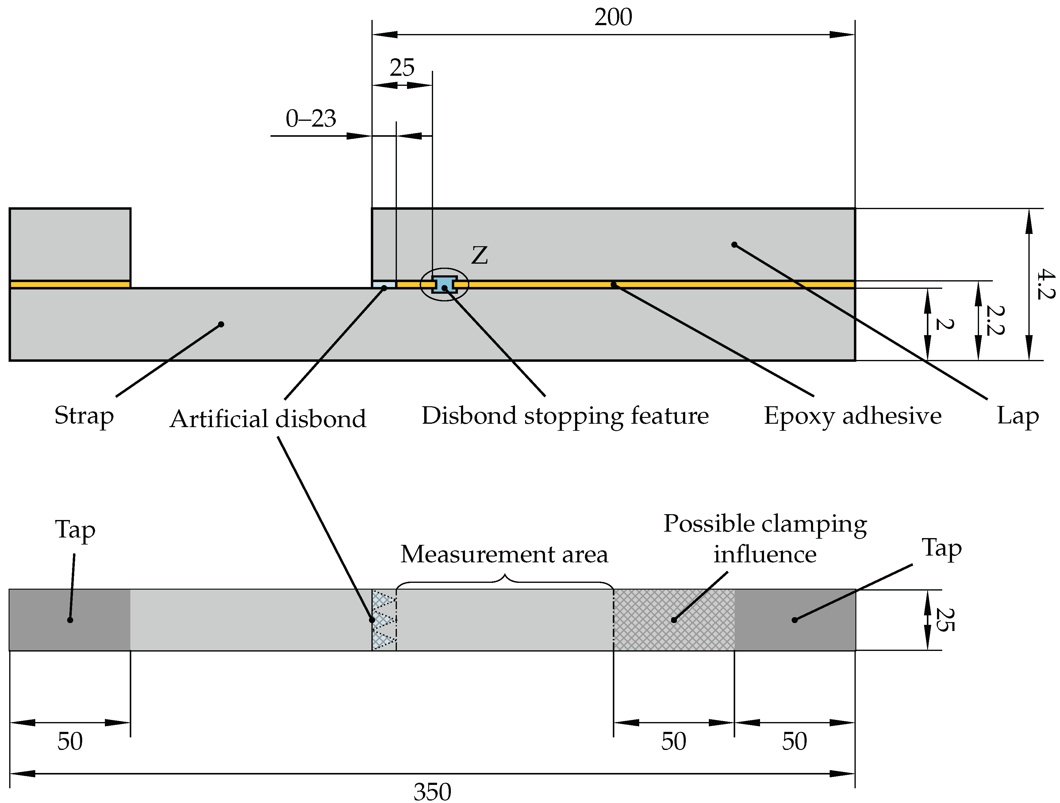
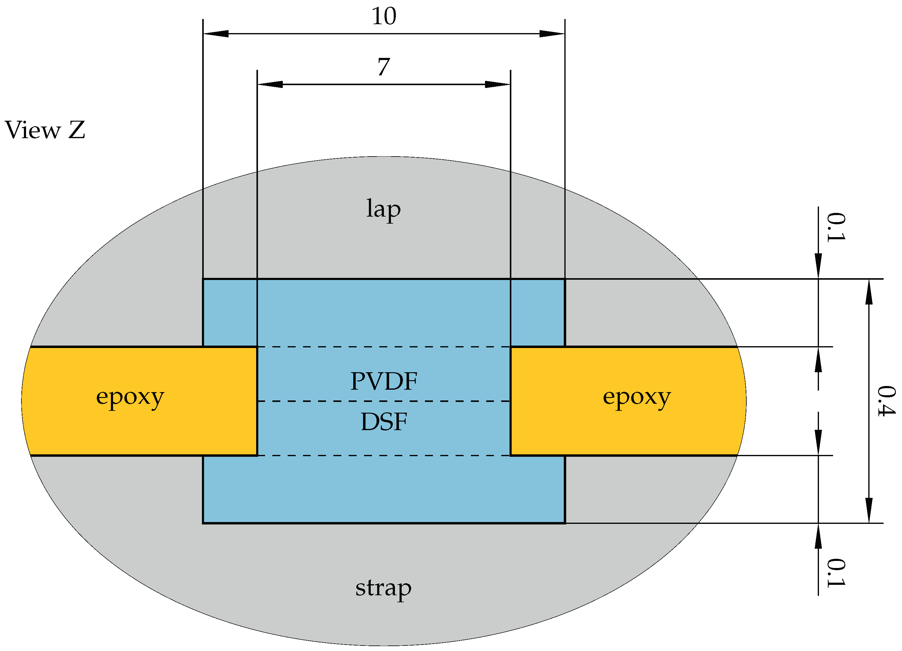
2.1. Specimen and Material Selection

CLS specimens as depicted in Figure 2 were chosen for studying the influence of the crack length on the stress distribution within the hybrid bondline under static loading. CLS specimens are a variation of lap strap joints by adding artificial disbonds at the overlap edge for the realization of defined crack lengths. The advantage of this configuration is the unambiguous crack initiation and crack growth direction [5]. Artificial disbonds of 0, 8, 16 and 23 m m in length were created in order to achieve one configuration without cracks, two with a crack ahead of the DSF, and one with a crack near the edge of the DSF, which lies 25 m m away from the overlap edge.
The carbon fiber reinforced plastic (CFRP) adherends (lap and strap) were made of HexPly 8552/IM7 unidirectional prepreg and bonded with the Loctite EA 9695 0.05 PSF K film adhesive. For the artificial disbonds, an ethylene tetrafluoroethylene (ETFE) release film was used. The DSFs were made from Kynar 740 PVDF supplied by Arkema. The specimen and material selection were in accordance with previous studies of hybrid bondlines [2,6].
The manufacturing steps for the CLS specimens were the same as described by Löbel et al. [2] for single lap shear specimens. First, two PVDF layers of 10 m m in length and 0.1 m m in thickness were co-cured to each adherend in an autoclave process. Then, the epoxy adhesive was placed in between the adherends with the area between the PVDF surface strips being left open. Two additional PVDF strips of 7 m m in length and 0.2 m m in overall thickness were placed in between the PVDF surface layers instead. Moreover, a release film was inserted at the overlap edge for all specimens with an artificial crack. The adhesive bonding and simultaneous thermoplastic welding of the PVDF strips was carried out in an autoclave. All dimension of the CLS specimens are depicted in Figure 2 and Figure 3. The dashed lines in Figure 3 indicate the four PVDF layers that are welded in the bonding process.

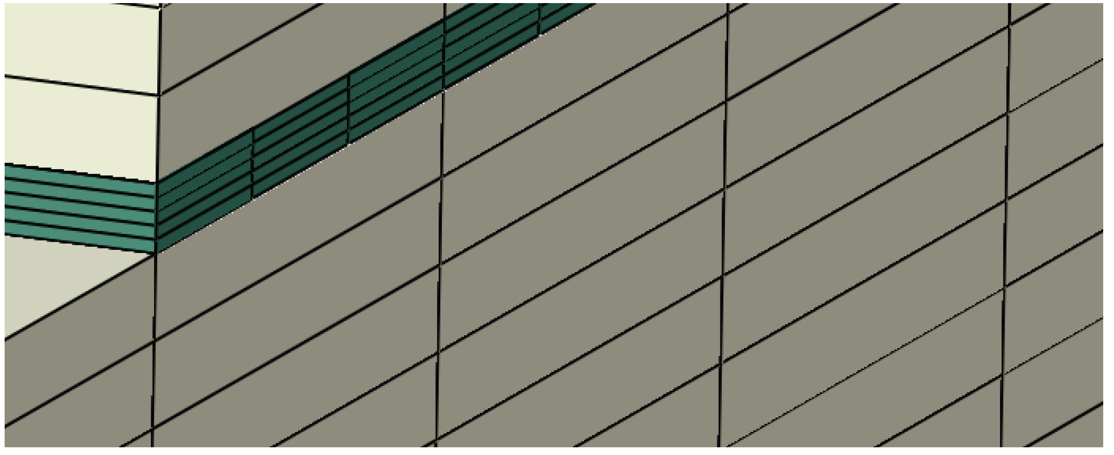
2.2. Finite Element Model of cls Specimens with Different Crack Lengths

FE analyses were used to study the tensile strain, as well as the shear stress distribution in the hybrid bondline of the CLS specimens with different crack lengths under static loading. The purpose of the simulations was to show the feasibility of crack detection by micro sensors in the PVDF-made DSF. The analyses of the 3D model were solved implicitly using Abaqus Version 2020.
The composite adherends of the specimen were modeled with a layer-wise approach using reduced integrated 8 node linear brick elements (C3D8R) with an in-plane edge-length of 1.0 m m and one element per layer in the thickness direction. Except for the region to be investigated, the same discretization applied for the adhesive. However, the adhesive region containing the artificial disbond and the DSF was discretized with solid elements with a 0.5% edge length and five elements for through-thickness as illustrated in Figure 4. This region was also first modeled with C3D8R, but the results showed a large scatter due to hourglass effects. Following [31], the element type was changed to fully integrated 8 node linear brick elements with incompatible modes (C3D8I) resulting in smoother stress and strain distributions.
To account for the hydrostatic pressure sensitivity of the film adhesive, the mechanical behavior was modeled with the exponent Drucker–Prager model using the Drucker–Prager parameters from a previous work [32]. The hardening curve was taken from [33]. The composite adherends made from HexPly 8552-IM7 were modeled as a linear-elastic transversally isotropic material using the material data from Marlett and Tomblin [34]. To justify neglecting the damage in the composite, a subroutine for user-defined output variables (UVARM) was used to calculate the material stress effort with the failure mode concept from Cuntze as described in [35,36]. The global material stressing effort was always below 50%, indicating no damage in the adherends at a loading of 6 k N . Therefore, it is not further discussed in the results.
The strap/lap side of the modeled specimen, shown in Figure 5, was fully clamped, and a 6 k N force was applied on the other strap-only side. The adherends were connected to the adhesive layer using tied contacts, and the artificial disbond was modeled by releasing the tied contact in the disbond area between the adhesive and the strap. The stress and strain values were evaluated at the element centroids by an Abaqus Python script using predefined element sets in the adhesive and DSF region.

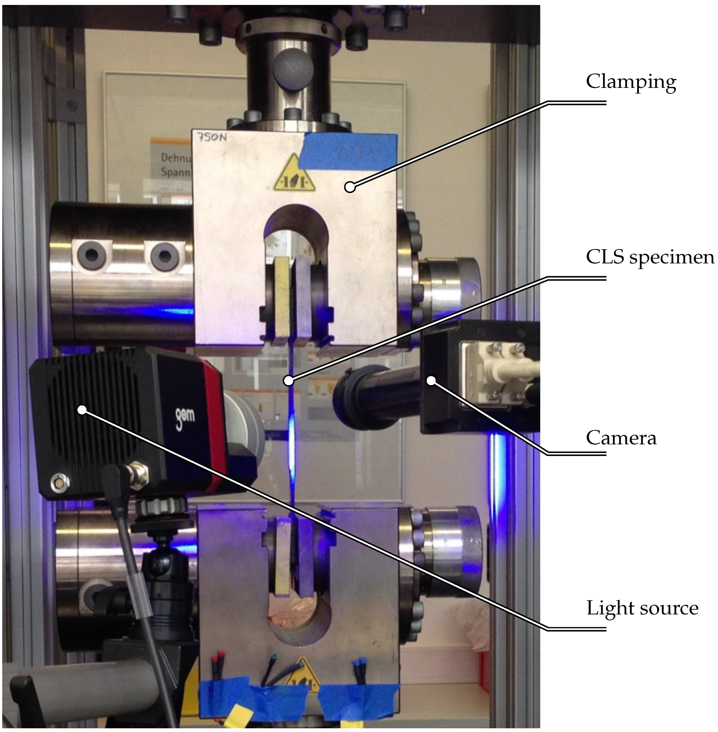
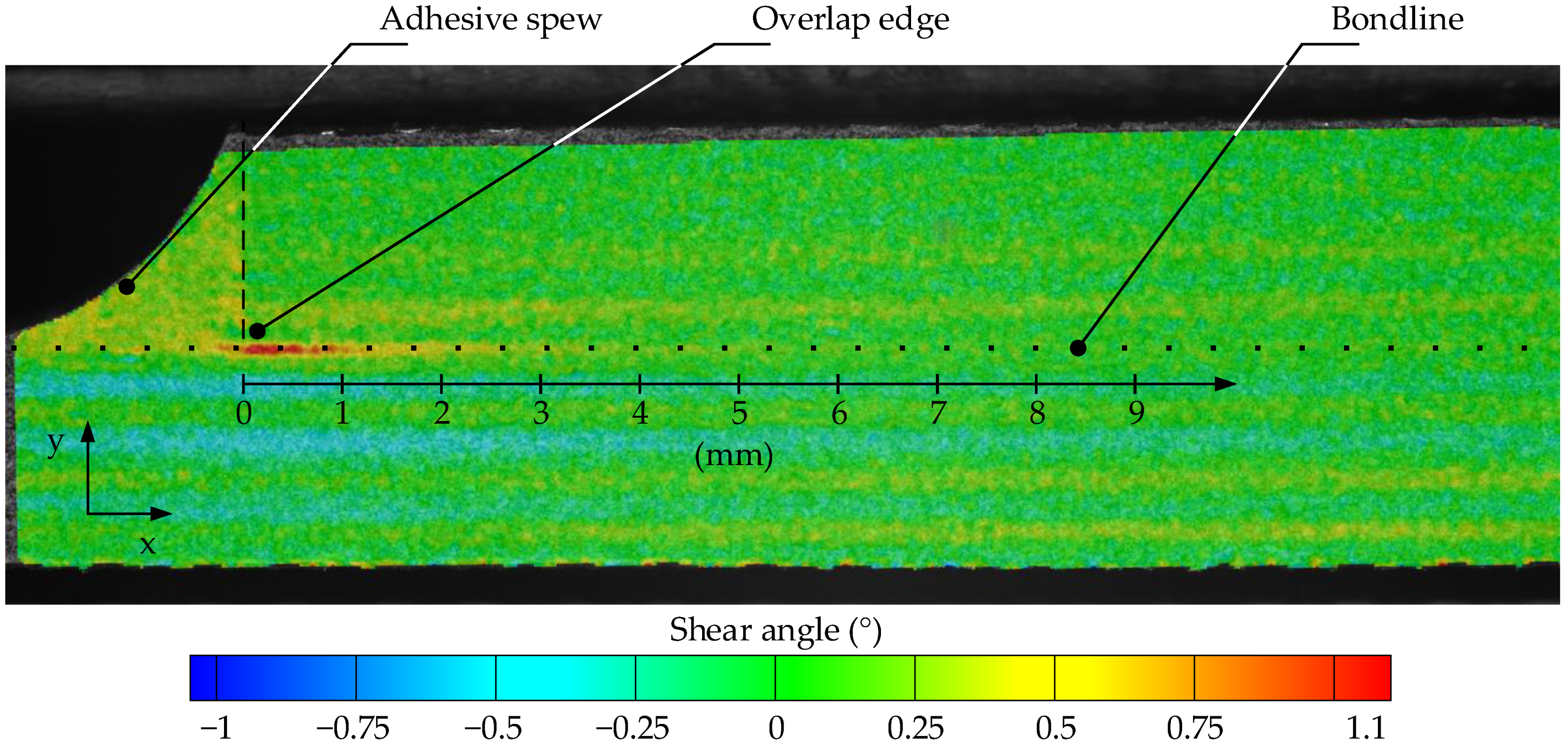
2.3. Shear Stress Measurements of cls Specimens with Different Crack Lengths in Static Tensile Tests

The influence of the crack length on the shear stress distribution within the bondline was studied experimentally by static testing of the CLS specimens in a tensile testing machine. All specimens were fully clamped in both tap areas and the tested displacement driven with 2 m m / min . The digital image correlation (DIC) system Aramis by GOM (software Version 6.3) was used for measuring the two-dimensional strain field of the specimens on one side. For the DIC measurements, a random speckle pattern was applied on the surface by dispersing white titanium dioxide and dark iron oxide powders in ethanol and spraying it on the probe with an air brush system. In the experimental setup, a single camera by GOM provided high resolution images for the two-dimensional measurements. Hence, a very fine facet size of 0.017 m m by 0.017 m m , equaling 15 pixels, was achieved. This allowed measuring the deformations of the thin bondline itself. The facets overlapped because a distance of 8 pixels was chosen between them. Errors and inaccuracies might be caused by facets, which overlapped the interface of the adhesive and the adherend. For that reason, the evaluation was carried out in the middle of the adhesive layer. The entire experimental setup is illustrated in Figure 6. Kosmann et al. [37] published a more detailed description of the measurement technique.
Testing the adhesive by the tube torsion method, in accordance with Kosmann et al. [38], showed plastic deformations at stresses above 30 M Pa . Due to the mixed mode in CLS probes, plastic deformations might occur even below shear stresses of 30 M Pa . The DIC measurements were thus evaluated at shear stresses below 30 M Pa , which equals a tensile load of the CLS specimens of 6 k N , in order to allow the comparison of the experimental data to the FE data obtained with a linear elastic material model. The shear stress distribution was derived by post-processing the images. The shear angle due to the deformation of the specimens was evaluated. In the evaluation, the superimposed rotations and rigid body movements of the facet fields that disturbed the shear angle measurement were automatically tracked and corrected accordingly.

3. Results

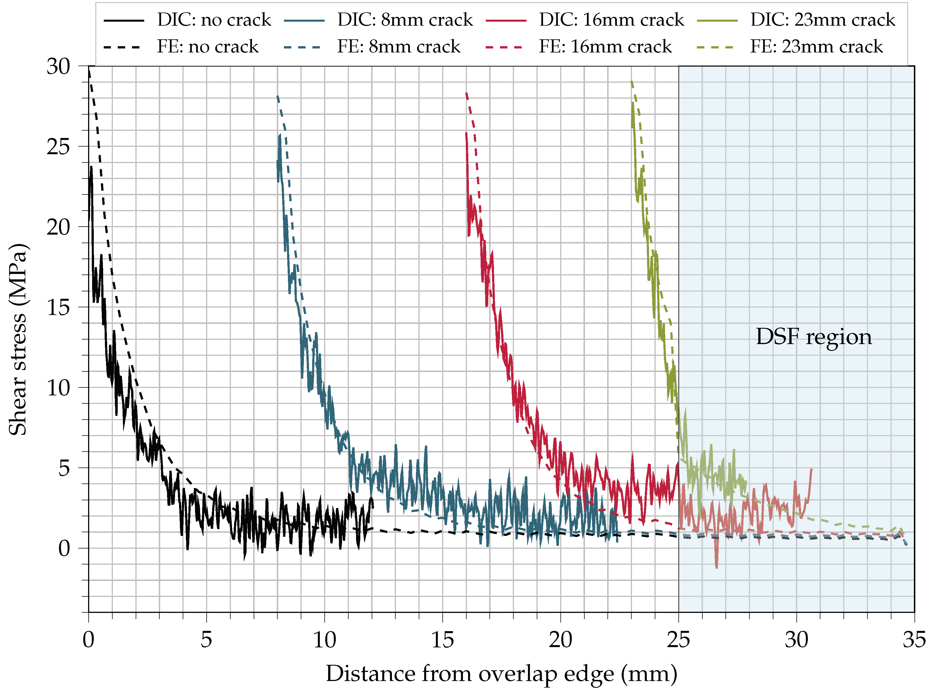
3.1. Shear Stress Distribution within the Hybrid Bondline at Different Crack Lengths

The shear angle γ x y obtained from DIC measurements for an undamaged CLS probe is depicted in Figure 7. The shear angle peaks at the overlap edge and rapidly decreases until a plateau is reached. From the shear angle γ x y , the shear stress:
τ ( x ) = G a · t a n ( γ x y ( x ) ) G a · γ x y ( x )
along the x-coordinate as defined in Figure 7 is calculated considering the small angle approximation:
t a n ( γ x y ) γ x y .
The shear modulus G a of the adhesive was determined in a tube torsion test as described by Kosmann et al. [38] to 1118 M Pa . The same procedure was carried out for the specimens with artificial disbonds of 8, 16 and 23 m m in length. In Figure 8, the resulting shear stress distribution for all the different investigated crack lengths is illustrated. Despite the rather high scatter of the DIC data, the experimental results and the FE-model are in good agreement. Both show the expected hyperbolic shear stress distribution across the bondline peaking at the overlap edge.
As the crack travels through the bondline, the region behind the crack is unloaded. Hence, a new overlap edge is created at the crack tip. Consequently, the shear stress peak travels together with the crack tip. Moreover, a slight increase in the maximum shear stress is observed. In the case of the DIC measurements, no adhesive spew relieves the stress distribution anymore, while for the FE model, the increase may be explained due to the disbonded lap region, which provokes a higher stress concentration.
The biggest increase is reached at a crack length of approximately 23 m m . At this state, only a 2 m m long epoxy area at the overlap edge is directly followed by the much more compliant DSF. The curves of shorter cracks demonstrate that the biggest portion of the shear stress is transferred at the first 3 m m to 5 m m of the bondline before the stress plateau is reached. As the compliant PVDF is not capable of carrying as much load as the stiff epoxy, the biggest portion of the load must be transferred by the 2 m m short epoxy area, leading to the observed shear stress increase.
For finding sensor positions, at which the bondline is disturbed as little as possible, the area of the DSF is of great interest. In Figure 8, the DSF region, starting at a 25 m m distance from the overlap edge, is indicated by the blue background. As expected, the stress at the edge of the DSF increases when the crack approaches. For a crack length of 23 m m , a clear stress gradient is present within the DSF, whereas for crack lengths of 16 m m and below, the stress plateau is already reached.

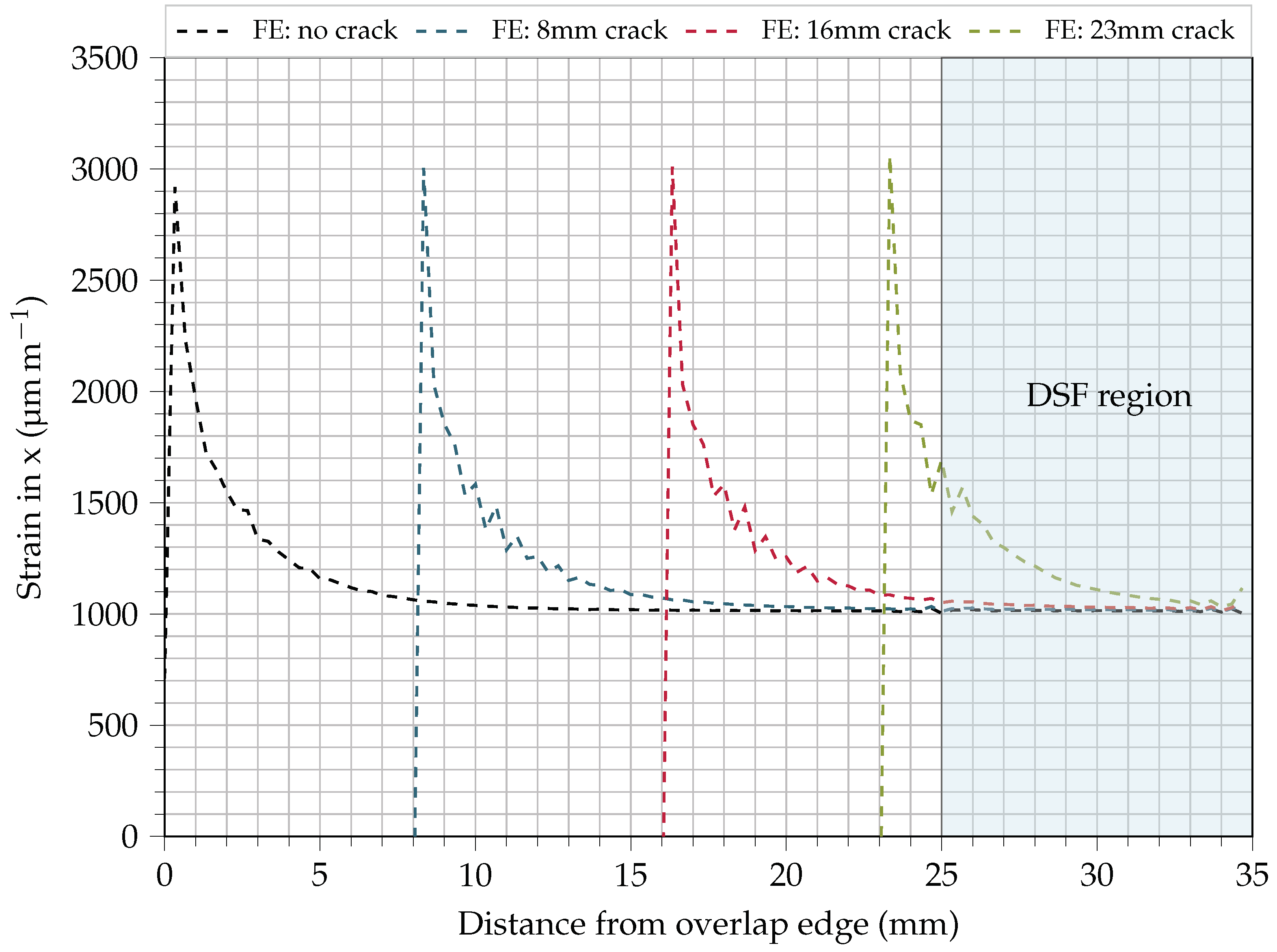
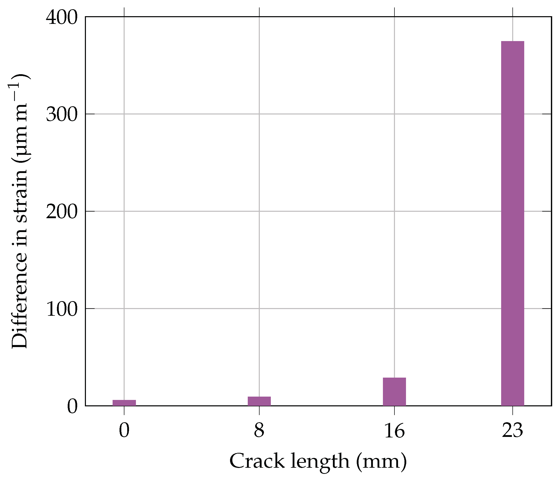
3.2. Tensile Strains within the Hybrid Bondline at Different Crack Lengths

The strain in the x-direction within the bondline is of interest for the implementation of an integrated SHM system as well. A clear change in the strain within the bondline due to a varying crack length enables the use of many conventional sensors such as FBG sensors and strain gauges for the damage detection. The strain in the x-direction within the hybrid bondline for different crack lengths is illustrated in Figure 9. The DIC measurements do not yield reliable results for the strain measurements. This is because the strain values are much smaller than the shear angles. As a result, the scatter of the data has a similar amplitude as the strain value. Thus, the evaluation of the strain is done solely by means of the FE simulation. The FE results indicate a similar behavior as obtained for the shear stresses before. Again, the strain peaks at the overlap edge, and the peak travels together with the crack tip. For all investigated crack lengths below 23 m m , the strain within the DSF shows nearly the same low level, while for longer cracks, an increase in strain at the edge of the DSF is observed. This increase is plausible because the lap is unloaded in the vicinity of the crack, whereas the strap is loaded more. Hence, the tensile strain within the lap and strap differ significantly at the overlap edge or crack tip. It takes approximately 3 m m –5 m m before the load in both adherends is equalized. In the area where the adherends are still bonded, but their strains are not the same, the bondline is deformed to compensate that difference. This deformation explains the slight increase in the strain within the bondline.
As the shear stress measurement and both simulation results show the expected behavior, they are considered trustworthy and allow for drawing further conclusions regarding the feasibility to embed sensors into the bondline for SHM purposes. In this context, possibilities to access the bondline integrity without disturbing the undamaged bondline are discussed, and the working principle of the multifunctional bondline is proposed based on these findings in the following.

4. Discussion

4.1. The Working Principles of the Multifunctional Bondline

In accordance with the three main functions of the hybrid bondline, the working principles must fulfill the joint of the adherends, crack stop mechanism, and damage detection. Structural adhesives such as epoxy film adhesives offer state-of-the-art solutions for joining adherends. In the scope of the hybrid bondline and the ST element development, the working principle to arrest cracks by unloading the crack tip with integrated thermoplastic strips has also been derived in previous studies. The main focus is thus on adding a working principle for achieving the damage detection within the bondline, additionally. For this matter, the stress and strain distribution within the bondline are evaluated regarding the question of whether and how these quantities can provide information on the bondline integrity.
Figure 8 shows a significant change of the shear stress distribution in the bondline for different crack length. The most obvious indicator is the stress peak at the overlap edge of the undamaged bondline that travels with the crack tip once a damage is initiated. Alternatively, the tensile strains in the x-direction within the entire bondline, which are related to the shear stress distribution, are a suitable damage indicator. The latter principle has the advantage that one-dimensional strain measurements in the x-direction are sufficient. Hence, FBG sensors with multiple measurement grids can be integrated into the bondline for obtaining the strain distribution for example. In conclusion, monitoring the shear stress or strain distribution of the entire bondline is a feasible method for damage assessment.
As mentioned before, it is key to integrate the SHM system in a function-compliant manner, i.e., without reducing the initial strength of the bondline and the capability of the DSF to stop cracks at the limit load level. Whether or not this is the case for an SHM system that is placed across the entire bondline is questionable. On the other hand, Löbel et al. [2] already developed a concept for adding a DSF while maintaining the initial strength of the bondline. That is why the integration of sensors for an SHM system into the DSF only is considered a promising way to ensure a function-compliant integration. The question is whether or not measuring the stress or strain only in the DSF instead of the entire bondline is still sufficient for a reliable damage assessment. The experimental results indicate a change of the stress and strain inside the DSF when a crack approaches. The drop in the shear stress or strain from the peak to the plateau offers a damage criterion by measuring at two discrete positions distributed on the x-axis within the DSF and a comparison of both values. In the undamaged state, both sensors ought to show the same output because the stress or strain plateau is measured at both measurement points. As the crack in the bondline moves forward, the sensor output at the measurement point closer to the crack front increases more than the one of the reference sensor further away. Hence, a change in the difference of both signals is a possible damage indicator. To illustrate this principle by an example, the strain signals of two virtual strain sensors placed 26 m m and 32 m m from the overlap edge are evaluated in the following. The two position were chosen according to the criteria that both sensors lie inside the 10 m m long DSF, that one sensor is close to the crack front, and that the distance between the sensors is big enough for the strain peak to decay for all investigated crack lengths. As can be seen from Figure 9, all criteria are fulfilled because the sensor at a 26 m m distance lies just at the edge of the DSF facing towards the crack front and the sensor at 32 m m lies near the other end of the DSF at a position where all strain values have reached the plateau. In Figure 10, the difference in the strain output of both virtual sensors is shown for all four crack lengths with the strain values taken from the FE simulation. For the crack lengths below 16 m m , the difference is nearly zero, before it increases slightly with the rising signal of the sensor at 26 m m , while the one at 32 m m stays the same as before. At a 23 m m crack, the difference between the two sensors reaches over 300 μ m / m .
The data suggest that damages are also accessible by measurements only in the DSF once the damage has almost reached the DSF. Using this method, a damage is thus detected later than for a method that relies on measuring the entire bondline. The hybrid bondline, however, is designed to maintain the limit load capacity as long as a crack is arrested at the DSF. Hence, a SHM system detecting damages in the vicinity of the DSF has the capability to indicate failed bondline sections before a critical global damage size is reached. Evolving the DSF to a MDAF by adding a micro sensor system for shear stress or tensile strain measurements to the DSF is thus considered a feasible method to realize a multifunctional bondline whose initial strength is similar to an undamaged conventional epoxy bondline. As long as the mechanical behavior of the DSF is not altered significantly by the presence of the SHM system, the crack stopping capability is likely to be maintained. As a result, the third working principle to fulfill the damage detection within the bondline is the stress or strain measurement by means of a sensor system integrated into the DSF.

4.2. The Multifunctional Disbond Arrest Feature

Based on the derived working principle in the previous section, two concepts are proposed for the novel MDAF. The first concept depicted in Figure 11 relies on the hybrid bondline principle. The PVDF material used as the DSF belongs to the class of ferroelectric polymers, and it can show piezoelectric properties [30,39]. While these properties are not addressed in the original hybrid bondline approach, their activation enables measuring the shear stress or tensile strain with the same material as used for the DSF. In this case, only electrodes and a signal transmission have to be added to the DSF. For the piezoelectric activation, the -phase of the PVDF material is required. During manufacturing, however, the PVDF is melted, and it crystallizes to the non-piezoelectric -phase when cooled down [40]. The conversion from the - to -phase is normally achieved by stretching the PVDF at elevated temperatures and stretch ratios of approximately five. However, these high strains cannot be realized in the bonded part by far. Thus, a method is required either to maintain the -phase throughout or to retrieve it after the adhesive bonding process. If this is achieved, the MDAF depicted in Figure 11 consisting of a stack of electrodes and piezoelectrically active PVDF that is joined to the outer non-polar PVDF is a possible solution.
A second concept relying on the ST principle is depicted in Figure 12. In this concept, micro sensor arrays are applied to the thermoplastic strips for stress or strain measurements. The clue of this concept is to use the DSF material as a substrate for thin film sensors. By using sensor arrays instead of single sensors, the proposed differential measurement method can be realized. Due to the ultra-thin sensor structures, the additional material input to achieve the sensor function is almost negligible, and therefore, the disturbance of the bondline is minimal if good adhesion between all interfaces is achieved. In contrast to the first concept, the phase of the PVDF material is not important for the functionality of the embedded sensor in the second one. Nevertheless, a reliable manufacturing process is also challenging because at least four materials with different thermal expansion coefficients have to be joined at high temperatures in this concept. The resulting thermal stresses could damage the micro sensors for instance.
The high level of function integration in combination with placing the sensors away from the load concentration at the initial overlap edges in both MDAF concepts is considered a very promising approach for the realization of the multifunctional bondline without disturbing the epoxy regions. Thus, a similar mechanical strength as reported for the hybrid bondline is expected. For a fully function-compliant multifunctional bondline, further studies with the MDAF are necessary to test the hypothesis that all three functions can be fulfilled simultaneously by the integration of micro sensors into the DSF only.

5. Conclusions

The experimental investigation and FE modeling of CLS specimens with integrated DSF illustrate a significant change in the stress and the strain distribution within the DSF of the hybrid bondline for different crack lengths. For an undamaged bondline and all cracks whose tip is further away than 7 m m from the DSF, a stress and strain plateau within the DSF is observed. The level of the plateau is significantly lower than the one at the overlap edge or crack tip. At a crack distance of 2 m m to the DSF, the stress and strain distribution within the DSF changes noticeably. In this configuration, a peak is present at the beginning of the DSF, which decreases until the level of the plateau is reached. The results demonstrate that a SHM system based on thin film micro sensors, localized in the DSF only, is capable of monitoring the bondline integrity. From the investigation and the previous work regarding the hybrid bondline, the three main working principles of the multifunctional bondline are derived. In summary, these are joining the adherends by means of structural adhesives, implementing a fail-safe mechanism due to crack arrest by adding ductile thermoplastic strips to the bondline, which unload the crack tip, and accessing damages by means of shear stress or strain measurements within the DSF. For the latter, measuring the difference of at least two neighboring sensors inside of the DSF is a promising approach.
Two concepts for a MDAF were proposed based on these results. The novelty of this MDAF approach lies in the combination of a design feature for limiting cracks to a specific length with integrated sensors for the SHM of the bondline. The positioning of the SHM away from the load peaks at the overlap edge of the undamaged bondline in combination with the high level of function integration is a promising approach for achieving a multifunctional bondline, whose initial mechanical strength is the same as the one for pure epoxy bondlines. The proposed multifunctional bondline has the potential to improve the safety of structural bonds significantly and to meet two of the three certification requirements of the aviation authorities for primary bonds. The multifunctional bondline approach is thus a step towards pure adhesive joining of safety critical composite structures.

Author Contributions

Conceptualization, J.S., C.H., M.S, C.v.d.H., and A.D.; methodology, J.S. and O.V.; software, O.V.; validation, J.S., T.L., and O.V.; formal analysis, J.S., T.L., and O.V.; investigation, T.L. and J.S.; resources, C.H. and M.S.; data curation, T.L., J.S., and O.V.; writing—original draft preparation, J.S., O.V., C.v.d.H., C.H., M.S., and A.D.; writing—review and editing, J.S.; visualization, J.S. and T.L.; supervision, C.H., M.S., and A.D.; project administration, C.H., A.D., and M.S.; funding acquisition, C.H., A.D., and M.S. All authors read and agreed to the published version of the manuscript.

Funding

This research was funded by the Deutsche Forschungsgemeinschaft (DFG, German Research Foundation)—401136681; We acknowledge support by the Deutsche Forschungsgemeinschaft (DFG, German Research Foundation) and the Open Access Publication Funds of Technische Universität Braunschweig.

Institutional Review Board Statement

Not applicable.

Informed Consent Statement

Not applicable.

Data Availability Statement

The raw data of the experiments can be requested from the authors.

Conflicts of Interest

The authors declare no conflict of interest. The funders had no role in the design of the study; in the collection, analyses, or interpretation of data; in the writing of the manuscript; nor in the decision to publish the results.

Abbreviations

The following abbreviations are used in this manuscript:
CFRPcarbon fiber reinforced plastic
CLScracked lap shear
DCBdouble cantilever beam
DICdigital image correlation
DSFdisbond-stopping feature
ETFEethylene tetrafluoroethylene
FBGfiber Bragg grating
FEfinite element
MDAFmultifunctional disbond arrest feature
NDInon-destructive inspection
PVDFpolyvinyliden fluorid
SHMstructural health monitoring
SLSsingle lap shear
STsurface toughening

References

  1. Campbell, F.C. Manufacturing Technology for Aerospace Structural Materials, 1st ed.; Aerospace Engineering Materials Science; Elsevier; Elsevier: Amsterdam, The Netherlands, 2006. [Google Scholar] [CrossRef]
  2. Löbel, T.; Holzhüter, D.; Sinapius, M.; Hühne, C. A hybrid bondline concept for bonded composite joints. Int. J. Adhes. Adhes. 2016, 229–238. [Google Scholar] [CrossRef]
  3. European Union Aviation Safety Agency. Annex II to ED Decision 2010/003/R of 19/07/2010: EASA. 2010. Available online: https://www.easa.europa.eu/sites/default/files/dfu/Annex%20II%20-%20AMC%2020-29.pdf (accessed on 25 May 2020).
  4. Federal Aviation Administration. Advisory Circular 20-107B Subject: Composite Aircraft Structure: FAA. 2009. Available online: https://www.faa.gov/regulations_policies/advisory_circulars/index.cfm/go/document.information/documentID/99693 (accessed on 25 May 2020).
  5. Löbel, T. The Hybrid Bondline: A Novel Disbond-Stopping Design for Adhesively Bonded Composite Joints. Ph.D. Thesis, Technische Universität Carolo-Wilhelmina zu Braunschweig, Braunschweig, Germany, 2016. [Google Scholar]
  6. Löbel, T.; Holzhüter, D.; Hühne, C. Disbond-Stopping Concepts for Bonded Composite Joints. SAMPE J. 2017, 53, 22–31. [Google Scholar]
  7. Schollerer, M.J.; Kosmann, J.; Holzhüter, D.; Bello-Larroche, C.; Hühne, C. Surface toughening—An industrial approach to increase the robustness of pure adhesive joints with film adhesives. Proc. Inst. Mech. Eng. Part G J. Aerosp. Eng. 2020, 234, 1980–1987. [Google Scholar] [CrossRef]
  8. Schollerer, M.J.; Kosmann, J.; Völkerink, O.; Holzhüter, D.; Hühne, C. Surface toughening—A concept to decrease stress peaks in bonded joints. J. Adhes. 2019, 95, 495–514. [Google Scholar] [CrossRef]
  9. Baker, A.A.; Scott, M.L. (Eds.) Composite Materials for Aircraft Structures, 3rd ed.; AIAA Education Series; American Institute of Aeronautics and Astronautics Inc.: Reston, VA, USA, 2016. [Google Scholar]
  10. Ehrhart, B.; Valeske, B.; Muller, C.-E.; Bockenheimer, C. Methods for the Quality Assessment of Adhesive Bonded CFRP Structures—A Resumé. In Proceedings of the 2nd International Symposium on NDT in Aerospace, Hamburg, Germany, 22–24 November 2010. [Google Scholar]
  11. Malinowski, P.; Wandowski, T.; Ostachowicz, W. The use of electromechanical impedance conductance signatures for detection of weak adhesive bonds of carbon fiber–reinforced polymer. Struct. Health Monit. 2015, 14, 332–344. [Google Scholar] [CrossRef]
  12. Yılmaz, B.; Jasiūnienė, E. Advanced ultrasonic NDT for weak bond detection in composite-adhesive bonded structures. Int. J. Adhes. Adhes. 2020, 102, 102675. [Google Scholar] [CrossRef]
  13. Zhuang, Y.; Li, Y.H.; Kopsaftopoulos, F.; Chang, F.K. A self-diagnostic adhesive for monitoring bonded joints in aerospace structures. In Sensors and Smart Structures Technologies for Civil, Mechanical, and Aerospace Systems; SPIE Proceedings, Lynch, J.P., Eds.; SPIE: Bellingham, WA, USA, 2016; p. 98030I. [Google Scholar] [CrossRef]
  14. Malinowski, P.; Wandowski, T.; Ostachowicz, W. Characterization of CFRP Using Laser Vibrometry. Key Eng. Mater. 2013, 569–570, 710–717. [Google Scholar] [CrossRef]
  15. Ehrhart, B.; Ecault, R.; Touchard, F.; Boustie, M.; Berthe, L.; Bockenheimer, C.; Valeske, B. Development of a laser shock adhesion test for the assessment of weak adhesive bonded CFRP structures. Int. J. Adhes. Adhes. 2014, 52, 57–65. [Google Scholar] [CrossRef]
  16. Ehrhart, B. Quality Assessment of Bonded Primary CFRP Structures by Means of Laser Proof Testing. Ph.D. Thesis, Universität Bremen, Bremen, Germany, 2016. [Google Scholar]
  17. Lammering, R.; Gabbert, U.; Sinapius, M.; Schuster, T.; Wierach, P. Lamb-Wave Based Structural Health Monitoring in Polymer Composites, 1st ed.; Research Topics in Aerospace; Springer International Publishing: Cham, Switzerland, 2017. [Google Scholar]
  18. Schmidt, D.; Sinapius, M.; Wierach, P. Design of mode selective actuators for Lamb wave excitation in composite plates. CEAS Aeronaut. J. 2013, 4, 105–112. [Google Scholar] [CrossRef] [Green Version]
  19. Li, B.; Liu, Y.; Gong, K.; Li, Z. Damage localization in composite laminates based on a quantitative expression of anisotropic wavefront. Smart Mater. Struct. 2013, 22, 065005. [Google Scholar] [CrossRef]
  20. Li, B.; Ye, L.; Li, Z.; Ma, Z.; Kalhori, H. Quantitative identification of delamination at different interfaces using guided wave signals in composite laminates. J. Reinf. Plast. Compos. 2015, 34, 1506–1525. [Google Scholar] [CrossRef]
  21. Ong, W.H.; Rajic, N.; Chiu, W.K.; Rosalie, C. Lamb wave–based detection of a controlled disbond in a lap joint. Struct. Health Monit. 2018, 17, 668–683. [Google Scholar] [CrossRef]
  22. Weiland, J.; Hesser, D.F.; Xiong, W.; Schiebahn, A.; Markert, B.; Reisgen, U. Structural health monitoring of an adhesively bonded CFRP aircraft fuselage by ultrasonic Lamb Waves. Proc. Inst. Mech. Eng. Part G J. Aerosp. Eng. 2020, 234, 2000–2010. [Google Scholar] [CrossRef]
  23. Dugnani, R.; Chang, F.K. Analytical model of lap-joint adhesive with embedded piezoelectric transducer for weak bond detection. J. Intell. Mater. Syst. Struct. 2017, 28, 124–140. [Google Scholar] [CrossRef]
  24. Adams, C.; Harput, S.; Cowell, D.; Freear, S.; Charutz, D.M. Specimen-agnostic guided wave inspection using recursive feedback. In Proceedings of the 2016 IEEE International Ultrasonics Symposium (IUS), Tours, France, 18–21 September 2016; IEEE: Piscataway, NJ, USA, 2016; pp. 1–4. [Google Scholar] [CrossRef] [Green Version]
  25. Charutz, D.M.; Mor, E.; Harput, S.; Cowell, D.M.J.; Smith, P.R.; Freear, S. Guided wave enhancement phased array beamforming scheme using recursive feedback. In Proceedings of the 2013 Joint UFFC, EFTF and PFM Symposium, Prague, Czech Republic, 21–25 July 2013; IEEE: Piscataway, NJ, USA, 2013; pp. 166–169. [Google Scholar] [CrossRef]
  26. da Silva, L.F.; Moreira, P.; Loureiro, A. Determination of the strain distribution in adhesive joints using Fiber Bragg Grating (FBG). J. Adhes. Sci. Technol. 2014, 28, 1480–1499. [Google Scholar] [CrossRef] [Green Version]
  27. Webb, S.; Shin, P.; Peters, K.; Zikry, M.A.; Stan, N.; Chadderdon, S.; Selfridge, R.; Schultz, S. Characterization of fatigue damage in adhesively bonded lap joints through dynamic, full-spectral interrogation of fiber Bragg grating sensors: 1. Experiments. Smart Mater. Struct. 2014, 23, 025016. [Google Scholar] [CrossRef]
  28. Canal, L.P.; Sarfaraz, R.; Violakis, G.; Botsis, J.; Michaud, V.; Limberger, H.G. Monitoring strain gradients in adhesive composite joints by embedded fiber Bragg grating sensors. Compos. Struct. 2014, 112, 241–247. [Google Scholar] [CrossRef]
  29. Preisler, A.; Sadeghi, Z.; Adomeit, A.; Schröder, K.U. Damage Assessment in Adhesively Bonded Structures by Using SmartSHM. In Structural Health Monitoring 2015; Chang, F.K., Kopsaftopoulos, F., Eds.; DEStech Publisher: Lancaster, PA, USA, 2015. [Google Scholar] [CrossRef]
  30. Sinapius, J.M. Adaptronics—Smart Structures and Materials; Springer Berlin Heidelberg: Berlin/Heidelberg, Germany, 2021. [Google Scholar] [CrossRef]
  31. Hühne, C.; Zerbst, A.K.; Kuhlmann, G.; Steenbock, C.; Rolfes, R. Progressive damage analysis of composite bolted joints with liquid shim layers using constant and continuous degradation models. Compos. Struct. 2010, 92, 189–200. [Google Scholar] [CrossRef]
  32. Völkerink, O.; Kosmann, J.; Schollerer, M.J.; Holzhüter, D.; Hühne, C. Strength prediction of adhesively bonded single lap joints with the eXtended Finite Element Method. J. Adhes. 2019, 95, 474–494. [Google Scholar] [CrossRef]
  33. Tomblin, J.; Seneviratne, W.; Escobar, P.; Yoon-Khian, Y. Shear Stress-Strain Data for Structural Adhesives: Technical Report. Available online: http://www.tc.faa.gov/its/worldpac/techrpt/ar02-97.pdf (accessed on 25 October 2020).
  34. Marlett, K. Hexcel 8552 IM7 Unidirectional Prepreg 190 gsm & 35%RC Qualification Material Property Data Report: Report Number: CAM-RP-2009-015 RevA. Available online: https://www.niar.wichita.edu/coe/ncamp_documents/Hexcel%208552/CAM-RP-2009-015%20Rev%20A%20April%2022%202011%20Hexcel%208552%20IM7%20Uni%20Data%20Report.pdf (accessed on 25 October 2020).
  35. Petersen, E.; Cuntze, R.G.; Hühne, C. Experimental determination of material parameters in Cuntze’s Failure-Mode-Concept-based UD strength failure conditions. Compos. Sci. Technol. 2016, 134, 12–25. [Google Scholar] [CrossRef]
  36. Völkerink, O.; Petersen, E.; Koord, J.; Hühne, C. A pragmatic approach for a 3D material model considering elasto-plastic behavior, damage initiation by Puck or Cuntze and progressive failure of fiber-reinforced plastics. Comput. Struct. 2020, 236, 106280. [Google Scholar] [CrossRef]
  37. Kosmann, J.; Löbel, T.; Holzhüter, D.; Hühne, C.; Schollerer, M.J. High resolution digital image correlation strain measurements of adhesively bonded joints. In Proceedings of the 17th European Conference on Composite Materials, Munich, Germany, 26–30 June 2016; MAI Carbon Cluster Management GmbH: Augsburg, Germany, 2016. [Google Scholar]
  38. Kosmann, J.; Klapp, O.; Holzhüter, D.; Schollerer, M.J.; Fiedler, A.; Nagel, C.; Hühne, C. Measurement of epoxy film adhesive properties in torsion and tension using tubular butt joints. Int. J. Adhes. Adhes. 2018, 83, 50–58. [Google Scholar] [CrossRef]
  39. Bar-Cohen, Y. Electroactive Polymer (EAP) Actuators as Artificial Muscles: Reality, Potential, and Challenges, 2nd ed.; SPIE Press: Bellingham, WA, USA, 2004; Volume PM136. [Google Scholar]
  40. Martins, P.; Lopes, A.C.; Lanceros-Mendez, S. Electroactive phases of poly(vinylidene fluoride): Determination, processing and applications. Prog. Polym. Sci. 2014, 39, 683–706. [Google Scholar] [CrossRef]
Figure 1. State-of-the-art fail-safe mechanism with an additional bolted joint (left) and the hybrid bondline approach of Löbel et al. [2] with a disbond stopping feature (right).
Jcs 05 00051 g001
Figure 2. CLS specimen setup (all dimensions in mm; scale for length and width: 1:3; scale for thickness: 5:1; the detailed view Z is depicted in Figure 3).
Jcs 05 00051 g002
Figure 3. Setup of the DSF in all CLS specimens (all dimensions in mm; scales for length and width: 5:1; scale for thickness: 75:1; adherends (lap and strap) in gray, epoxy in yellow, and PVDF in blue; the dashed lines indicate the four PVDF layers welded during the bonding process).
Jcs 05 00051 g003
Figure 4. Overlap edge of the FEM model showing the different element sizes.
Jcs 05 00051 g004
Figure 5. FEM model of the CLS specimen with boundary conditions.
Jcs 05 00051 g005
Figure 6. Experimental setup of a CLS specimen in a tensile testing machine equipped with a DIC system.
Jcs 05 00051 g006
Figure 7. DIC contour plot of measured shear angle ( γ x z ) for a load of 5.95 k N of an undamaged CLS specimen; the overlap edge is indicated by the vertical dashed line and the middle of the bondline by the dotted line.
Jcs 05 00051 g007
Figure 8. DIC and FE results of the shear stress distribution within the hybrid bondline at four different crack lengths under 6 k N load; the DSF position starting at 25 m m is indicated by the blue background.
Jcs 05 00051 g008
Figure 9. FE results of the strain distribution within the hybrid bondline at four different crack lengths under 6 k N load; the DSF position starting at 25 m m is indicated by the blue background.
Jcs 05 00051 g009
Figure 10. Difference of the two virtual strain sensor outputs for different crack lengths; the two strain values are taken from the FE results in Figure 9 at a distance from overlap edge of 26 mm and 32 m m .
Jcs 05 00051 g010
Figure 11. Multifunctional disbond arrest feature concept with a piezoelectric PVDF sensor including electrodes as part of a PVDF stack acting as the DSF by using the hybrid bondline principle.
Jcs 05 00051 g011
Figure 12. Multifunctional disbond arrest feature concept with micro sensor arrays on a PVDF substrate that is co-cured to the CFRP adherends and simultaneously acts as a DSF by using the ST principle.
Jcs 05 00051 g012
Publisher’s Note: MDPI stays neutral with regard to jurisdictional claims in published maps and institutional affiliations.

