
Dielectric Constant Enhancement with Low Dielectric Loss Growth in Graphene Oxide/Mica/Polypropylene Composites

Department of Materials Science and Engineering, National Formosa University, Yunlin 632301, Taiwan
*
Author to whom correspondence should be addressed.
J. Compos. Sci. 2021, 5(2), 52; https://0-doi-org.brum.beds.ac.uk/10.3390/jcs5020052
Submission received: 31 December 2020
/
Revised: 1 February 2021
/
Accepted: 2 February 2021
/
Published: 8 February 2021
(This article belongs to the Special Issue Graphene Oxide Composites)
Abstract
:Polypropylene has been widely used as dielectric material in organic thin-film capacitors due to their high breakdown strength, low dielectric loss and self-healing capability. However, polypropylene’s energy density is relatively low. Increasing the energy density of polypropylene by adding materials with a high dielectric constant is commonly used. Still, it often leads to an increase in dielectric loss, lower dielectric strength and other shortcomings. In this study, a thin 2D platelet of mica/graphene oxide composite material was made from exfoliated mica as a substrate and attached by graphene oxide. The mica/graphene oxide platelets were added to polypropylene to make a plastic dielectric composite. The non-conductive flat inorganic additive can increase the dielectric constant and dielectric strength of the composite without increasing dielectric loss. The tiny mica/graphene oxide platelets can significantly improve the dielectric properties of polypropylene. The results show that by adding a small amount (less than 1 wt%) mica/graphene oxide, the relative dielectric constant of polypropylene can increase to more than 3.7 without causing an increase in dielectric loss and the dielectric strength of polypropylene can also enhance.
1. Introduction
Dielectric materials are widely used in electronics devices and systems [1,2,3,4,5]. Dielectric materials’ performance requires consideration of multiple characteristics such as dielectric constant (k or ε), dielectric loss (tan δ) and dielectric strength. Different applications will require different dielectric materials [6]. For examples, IC insulation materials with a low dielectric constant are required, dielectrics with high dielectric strength and low loss are necessary under a high electric field application.
The dielectric used can be gas, liquid and solid state, for solid dielectrics, both polymers and ceramics are common dielectric materials. Polymers have benefits such as flexibility, low process temperature and high breakdown voltage but usually with a small dielectric constant (mostly less than 10). Polymer dielectric is required for many applications such as capacitors and electronic packages. Ceramics are brittle, high process temperature, high dielectric constant but with a low breakdown voltage. Combining different materials as composites have been widely studied because composites can integrate other materials’ unique properties to produce specific properties to meet the different needs [7,8]. Therefore, many studies combine polymer and ceramics to be polymer-based composites as dielectrics, usually by filling a flexible polymer matrix with isolated particles of inorganic compounds to increase dielectric constant [9,10,11,12,13].
Polymer-based composites with a high dielectric constant can be classified into two types based on the fillers used: dielectric and conductive fillers composites [14]. For dielectric/dielectric composites, to find fillers with a high dielectric constant is very important. Some ferroelectric ceramics exhibit a dielectric constant as high as 103 to 105. Therefore, various ferroelectric-based ceramics have been widely used in dielectric/dielectric composites [15,16,17].
The conductor/dielectric composites are based on the percolation theory [14]. The composite’s dielectric constant increases with the increasing filler while the filler content is smaller than the percolation threshold value. While the filler content approaches to the percolation threshold, the dielectric constant reaches a very high value. When the conductive filler’s content is higher than the percolation threshold, the composite becomes a conductor. The percolation threshold is dependent on the shape, size and distribution of the conducting fillers [18,19,20,21,22].
No matter what filler is used, polymer matrices play a ke + y role in dielectric composites’ performance. Various polymers have been used because of their processability, flexibility, melting temperature, dielectric response and dielectric strength. Polypropylene (PP) film has been used as dielectric material in capacitors since the 1970s. The high breakdown strength, low dielectric losses and high processability make PP well suitable for polymer capacitor.
Breakdown strength of polypropylene is highest among common polymer films used in capacitor applications. PP also has a low dielectric loss and excellent self-healing capability that makes it suitable for the high electric field. On the other hand, PP has a relatively low dielectric constant only about 2.2 at room temperature, resulting in a typical energy density of 1.2 J/cm3 [23]. In high voltage and high-power applications, the use of polypropylene capacitors can achieve good results but they need a larger volume to achieve sufficient electrical capacity. Therefore, recent research on PP films for capacitors focuses on improving the dielectric constant and breakdown strength. Most of the strategies adopted are producing copolymers, blending with other polymers or adding inorganic particles [24,25]. There are many ways to increase dielectric constant and breakdown strength but only a little research shows positive results for maintaining the low dielectric losses.
There has been a lot of research on dielectric and electrical properties of inorganic fillers in polypropylene matrices, such as nano-fillers, carbon nanofiber, layered silicate, core in shell nanoparticles, carbon black and glass beads [26,27,28,29,30,31,32,33].
Adding inorganic fillers to polymers usually leads to deterioration of mechanical properties and loss of processing capacity. A small number of inorganic fillers in polymer composite can reduce mechanical properties’ deterioration but it will do little to improve dielectric properties [21]. Carbon-based fillers, including carbon nanotubes (CNTs), carbon black (CB) and graphene, attract a lot of attention of researchers because they exhibit excellent electrical properties and can improve dielectric constant of the polymer composites with relatively low concentration [34]. However, it is worth noting that the dielectric loss of these composites will also increase at the same time. This is mainly related to the formation of the electrically conductive pathway in the composites resulting in the leakage current [35].
Carbon-based fillers are usually conductive materials, to prevent the formation of the electrically conductive pathway on fillers surface in the composites, some methods have been developed, such as coating another polymer on carbon-based fillers surface [36]. Graphene is a single layer of carbon atoms arranged in a two-dimensional honeycomb lattice. Graphene oxide (GO) is graphene with many oxygen-containing groups on the surface and/or edges of the stacked graphene layers. There are many carboxyl and/or hydroxyl groups at the edges of graphene oxide platelets and on the surface of the platelets, there are some epoxy groups [37]. The presence of such oxygen-containing groups deteriorates the SP2 bonding orbitals and introduces the SP3 defect sites into graphene oxide and consequently, the electrical conductivity is greatly decreased compared with the graphene [38]. Because of the presence of oxygen-containing groups, graphene oxide usually exhibits high surface-to-surface interaction with polymer matrix through hydrogen bonds [39,40,41]. Oxygen-containing groups expand the interlayer distance what makes the layers hydrophilic, which provides favorable sites for bonding the foreign molecules [42,43,44]. Those suggest that graphene oxide can be used to enhance the mechanical properties of polymer composites.
The plane of carbon atoms of graphene oxide is modified by a large number of oxygen-containing groups, which may make interfacial polarization between graphene oxide and polymer. Interfacial polarization is possibly favorable for the enhancement of dielectric constant of polymer composites. Many studies have investigated the effects of graphene oxide on polymer composites’ dielectric properties [45,46,47].
Recently, graphene oxide has attracted significant attention due to its large surface area, porous structure and chemical stability, providing a platform for anchoring nanoparticles to enhance the performance of nanocomposite structures [48,49].
In this study, mica/graphene oxide platelet was used as the composite filler to increase polypropylene’s dielectric properties. The graphene oxide attached to the mica surface to form a sandwich structure, adding mica can help augment dielectric strength and graphene oxide with the high surface area, increasing the composite’s dielectric constant. The only small amount of mica/graphene oxide fillers was used in polypropylene to avoid increased dielectric loss, reduced mechanical strength and poor processability.
2. Materials and Methods
2.1. Materials
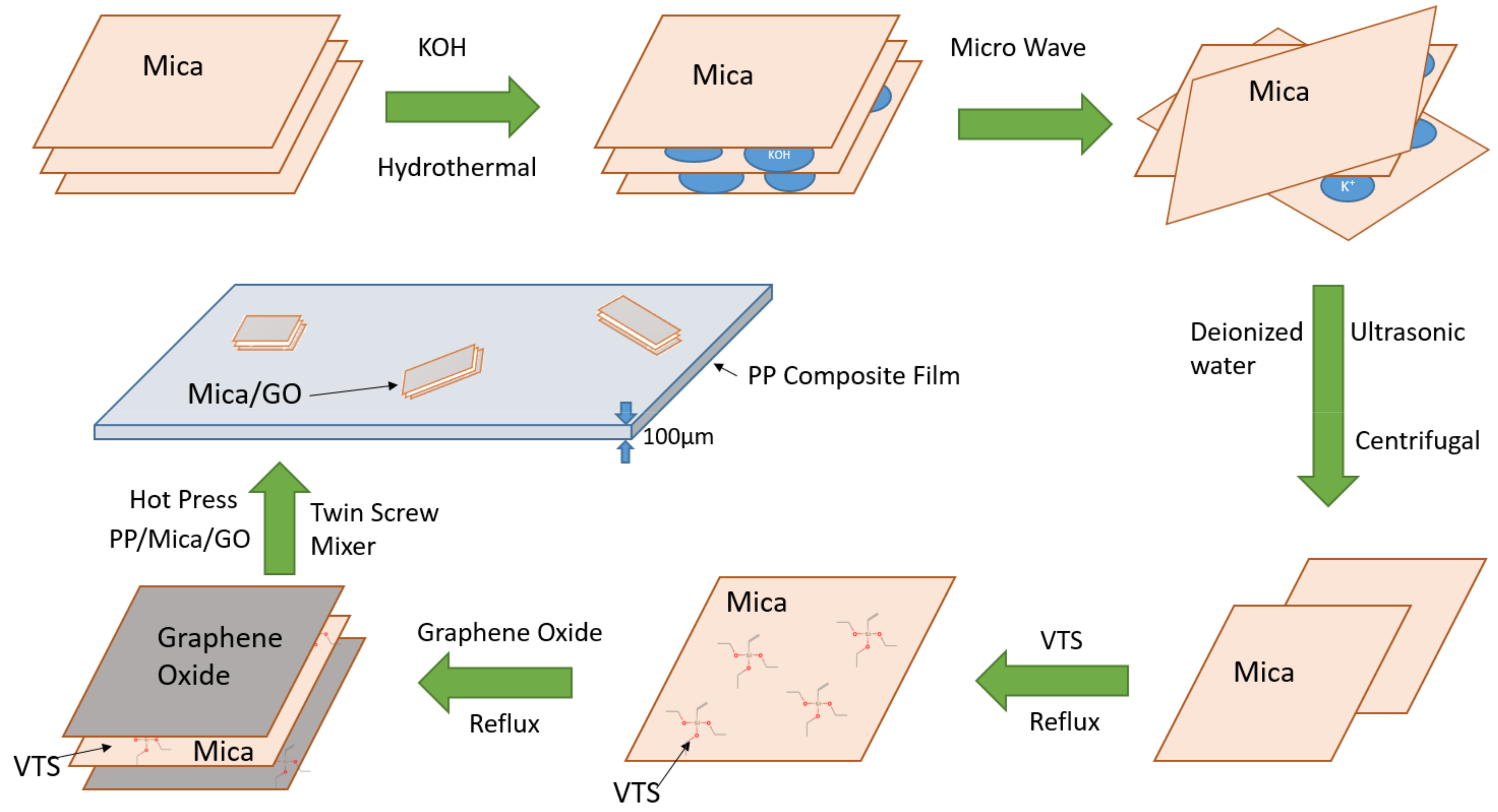
The mica platelets were prepared by ball milling and microwave-assisted hydrothermal method. The starting materials were natural mica film and they were milled by a planetary mill (Deco, Changsha, China) at 730 rpm for 1 h. The milling was conducted in a zirconia jar with zirconia balls. The milled powders were mixed with 0.9 M potassium hydroxide solution in an autoclave and then heated at 260 °C for 3 h to make potassium ions inserted into the mica layers. The mica powders were removed from solution to a microwave oven to heat in 600 W for 10 min. After microwave treatment, ultrasonicator and centrifuge were used to obtain mica platelets.
pH adjustment of methanol was made using acetate to pH 5 in a reflux device. About 1% Vinyltrimethoxysilane (VTS) (Sigma-Aldrich, St. Louis, United States, H2C-CHSi (OCH3)3) is added to the methanol solution for silane hydroxylation at 65 °C for 1 h. The mica platelets mixed with VTS solution and kept the temperature at 65 °C to enable the mica surface-functionalized. The graphene oxide gel (Angstron Materials, Dayton, OH, USA) mixed with methanol, ultrasonic for 1 h and then the graphene oxide solution added to the reflux device with mica/VTS solution, the weight ratio of mica and graphene oxide is 50:1, 50:3, 50:5, respectively. The mica surface with silane-functionalization makes it easy to attach graphene oxide forming graphene oxide/mica composite platelets.
The composite platelets were dried in a vacuum oven after silane-functionalization for 2 h and then mixed with PPgMA (Du Pont, Fusabond P613, Wilmington, NC, USA) at 1:3 weight ratio. The mica/graphene oxide/PPgMA and the PP (Japan Polypropylene Corporation EA9, Tokyo, Japan) particles were mixed and added to the twin-screw mixer together. The temperature was at 200 °C and the rotation rate was 70 rpm. Two kinds of the sample, PP/mica and PP/mica/ graphene oxide, had been prepared. The final weight ratio of PP/mica is 99.9:0.1, 99:1, for PP/mica/graphene oxide is 99.49:0.5:0.01, 99.47:0.5:0.05 and 99.45:0.5:0.05. Polypropylene composite is extruded and moved to an automatic press to hot press into a thin film at 215 °C. The complete production process shows in Figure 1.
2.2. Characterization
The mica platelet, silane-functionalized mica, mica/ graphene oxide platelets and PP composite was observed and evaluated.
The platelets and polymer film morphologies were observed by scanning electron microscopy (SEM, S-3500, Hitachi, Tokyo, Japan) and transmission electron microscopy (TEM JEM2010, JEOL, Tokyo, Japan).
Differential Scanning Calorimeters (DSC, Q2000, TA Instruments, New Castle, DE, USA) and Thermal Gravimetric Analyzer (TGA, Q500 TA Instruments) were applied to test thermostability of PP composites at a rate of 10 °C/min from 100 °C to 200 °C for DSC and from 200 °C to 500 °C for TGA, both in the nitrogen atmosphere. The Fourier transform infrared (FTIR) analysis of the mica/graphene oxide composites was carried out using a spectroscopy (IS10, Thermo Fisher Nicolet, Waltham, MA, USA) to characterize the interaction between mica and graphene oxide. The X-Ray Diffractometer (XRD, D8A25, Bruker, Cu Kα1 radiation, λ = 1.5418 Å) with a range from 14° to 60° was carried out to investigate the crystal phase of mica/graphene and PP before and from 10° to 25° for PP composites. Surface areas were obtained by applying the Brunauer-Emmett-Teller (BET, ASAP 2020, Micromeritics, New Taipei City, Taiwan) equation on the BET plot’s linear zone, using nitrogen gas as an adsorbate at liquid nitrogen temperature.
The capacitance of PP composite film with parallel silver paste electrodes is directly measured using LCR meter (6370, Microtest) at 1 kHz by the following equation:
where ε0 is the dielectric permittivity in vacuum and is 8.854 pF/m, εr is the relative permittivity, A is the area of parallel electrodes, d is the thickness of dielectric material, C is the electrical capacity.
C = εrε0A/d
The measurement of dielectric strength was following ASTM D149 standard. The alternating voltage at a commercial power frequency (60 Hz) is applied to a test specimen. The voltage is increased from zero until the dielectric failure of the test specimen occurs. The specimen size is about 11.5 × 11.5 × 1.2 mm. ASTM D149 [50] used a large area of samples to measure dielectric strength, so it is susceptible to small defects inside the specimen, resulting in low dielectric strength.
The tensile tests were conducted using 3 samples for each composition with the tensile testing machine (HT-2402, Hungta, Taichung, Taiwan) at room temperature. Tensile test for films is according to ASTM D882 standard, the thickness and width of the film are about 0.1 to 0.2 mm and 25 mm, gauge length is about 100 mm, the crosshead speed is 25 mm/min.
3. Results and Discussion
3.1. Mica/Graphene Oxide Composite Platelets
Mica is the group of sheet silicate (phyllosilicate) minerals that have a layered or platy texture. The crystalline structure of mica forms layers that can be split or delaminated into thin sheets. These sheets are dielectric, flexible, hydrophilic and insulating. Mica is stable when exposed to electricity and extreme temperatures. It has superior electrical properties as an insulator. As a dielectric, adding mica to the polymer can increase the polymer’s dielectric and mechanical properties. Mica can be split as very thin platelets while maintaining high dielectric breakdown, thermally stable and resistant to the corona discharge.
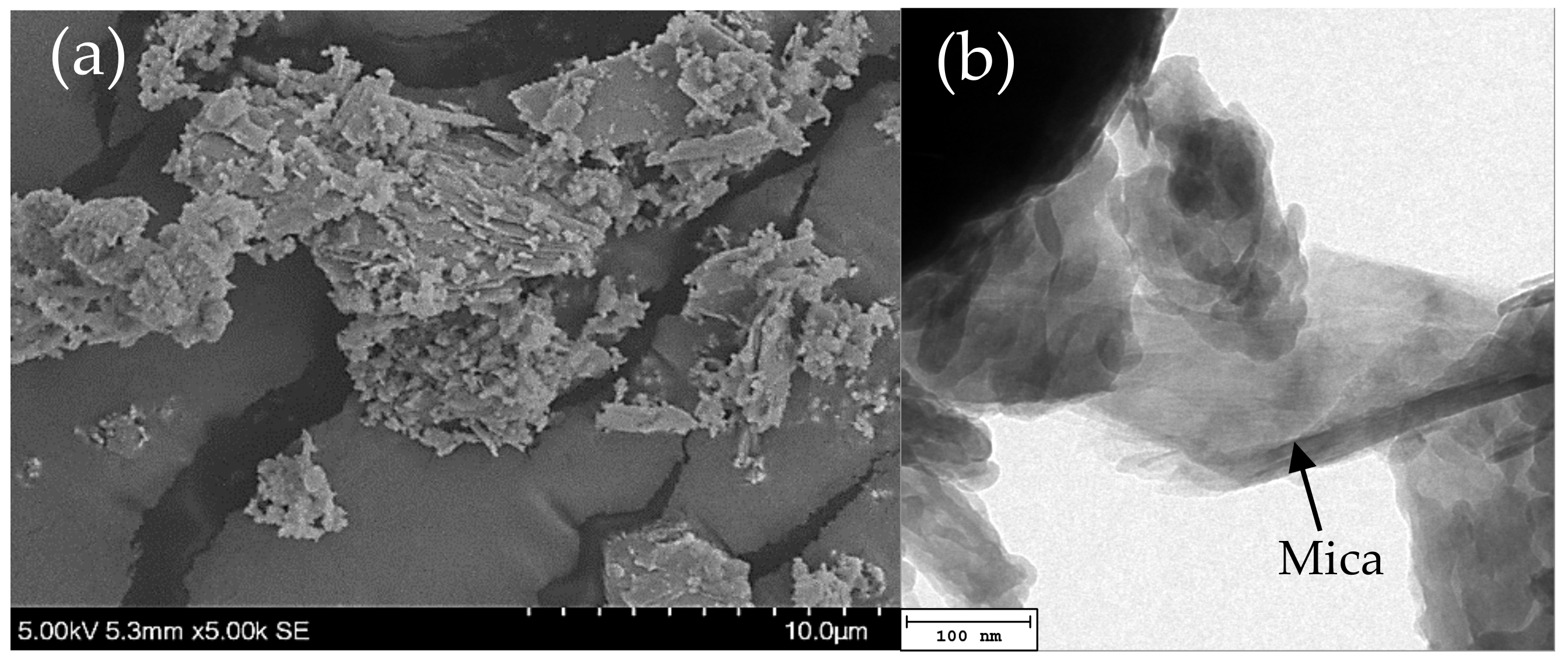
The mica layer’s exfoliation is made by potassium ions inserted into the mica and expanded using the microwave. Figure 2 shows electron microscopes’ observation in the various production stages of mica/graphene oxide composite platelets. Figure 2a is the SEM image of mica after the hydrothermal process and microwave expansion, flaky mica particles and many flat holes in bulk mica can be observed, representing that the hydrothermal and microwave method can exfoliate mica layer. Figure 2b is the BF TEM image of the mica platelet after centrifugation, we can see the flaky structure in the figure and the edge of the mica is barely visible. The mica’s superimposed layers can also be observed, indicating that the mica platelets’ thickness is quietly thin.
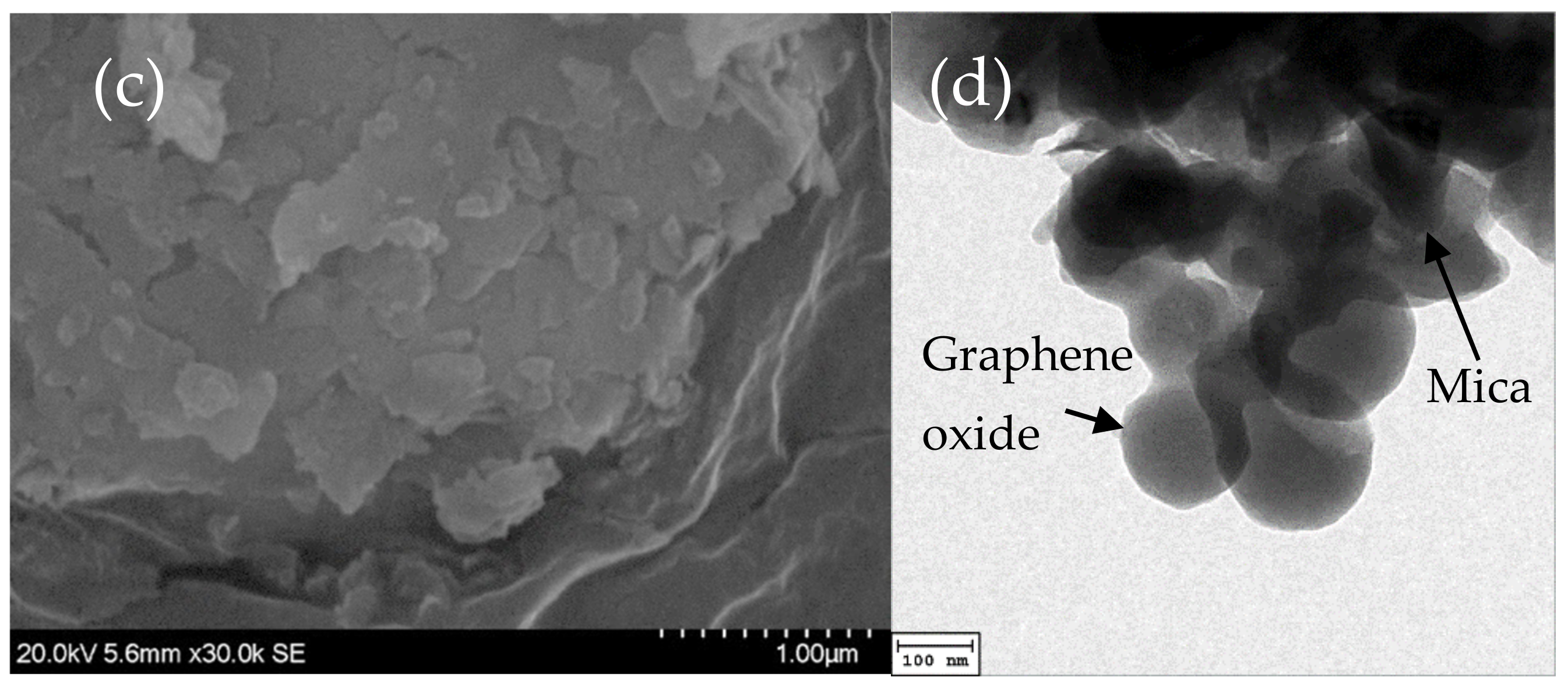
Figure 2c is the SEM image of silane-functionalized mica and we can observe that stacking of mica layers. Each platelet’s size is less than 1 micron because the silane-functionalization on mica surface, so it can be observed that the interface between the mica layer and layer is not fully attached. Figure 2d is a BF TEM photo of mica sheets with graphene oxide, also can be observed in a layered structure, because graphene oxide is attached, make the edges are not as sharp as mica. Mica is a brittle material; the edge is more prone to produce sharp appearance. Graphene oxide attachment allows the mica’s sharp edge to be smoother and can reduce the defects caused by the pointed mica tip in the Polypropylene composite.
The mismatch between the organic and inorganic phases makes it challenging to attach completely. Surface modifications for inorganic fillers were commonly employed in organic-inorganic composites to improve the interfacial compatibility to achieve desired performances [51]. Mica is an inorganic material and the surface is with polarity. Polypropylene is an organic material with nonpolar; if the two are not modified, in the mixing process will cause mica and polypropylene cannot be evenly mixed [52]. Therefore, we used the silane coupling agent VTS to help the combination of mica, graphene oxide and polypropylene. Silane needs to hydrolyze itself first; the speed of hydrolyzing is related to solvent, temperature and chemical structure. The mica surface partially absorbs the hydrolyzed silane to enhance mica surface wetting.
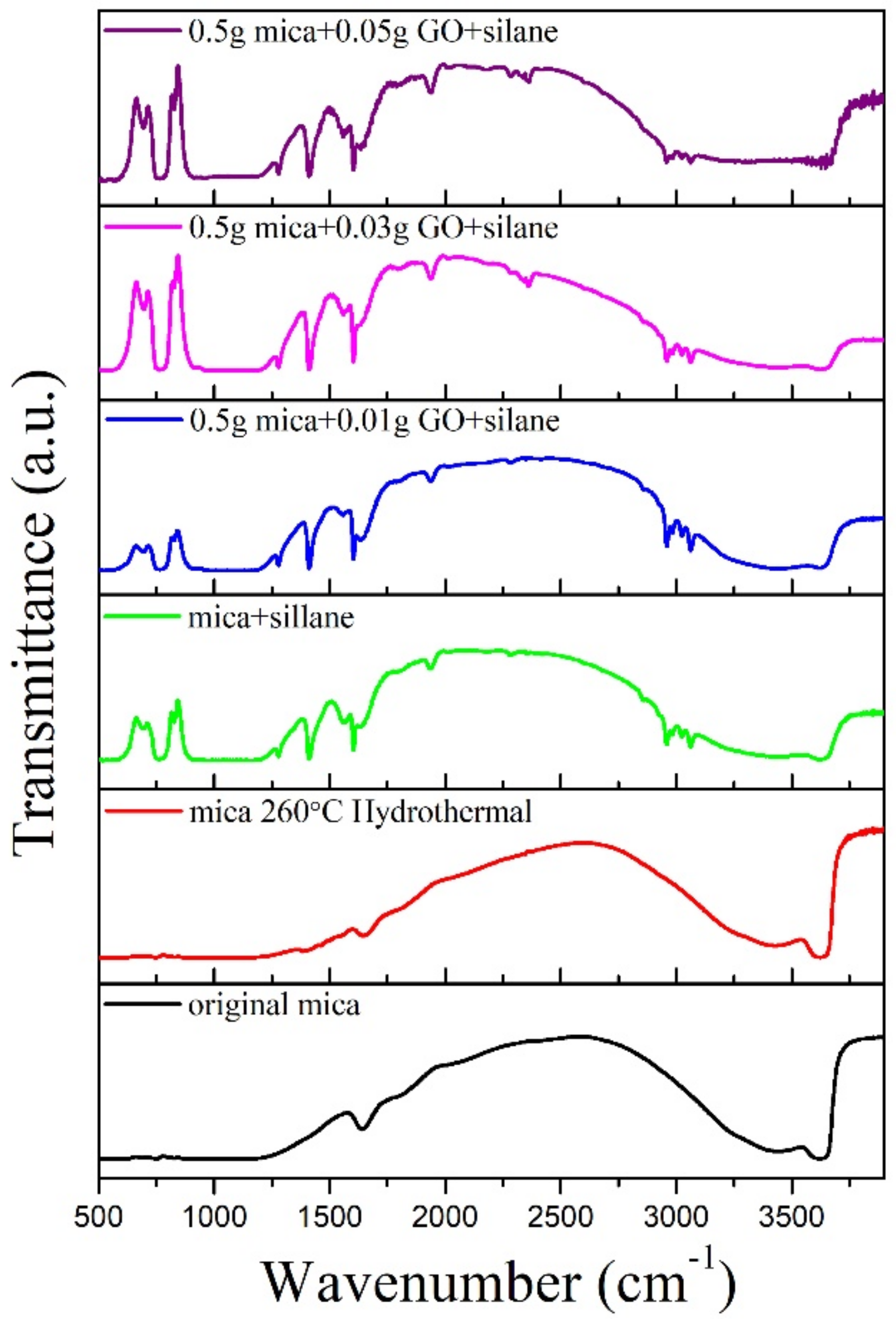
Figure 3 shows Fourier transform infrared (FTIR) spectra of mica and mica/graphene oxide before and after functionalization with silane. The results showed that the original mica and hydrothermal expansion mica both in the wavenumber 1640 and 3620 cm−1 have absorption peak corresponding to O-H group, indicating that after hydrothermal expansion, the number of mica layer decreased but the structure remains the same.
The FTIR spectra of silane-functionalized mica show that Si-O absorption peaks at wavenumbers 684, 765, 784, 1250 cm−1, C-H absorption peaks at 2972, 2964 cm−1 and C=O at 1635 cm−1, 1729 cm−1. C=C absorption peaks at wavenumbers 1615 cm−1, N-H absorption peaks at wavenumbers 1455 cm−1, -Si-O-CH3 characteristic absorption peak appears in 1192 cm−1. The absorption peaks mentioned above can directly prove the success of silane-functionalization on mica surface. C-C absorption peaks at wavenumbers 2350 cm−1 appeared in silane-functionalized mica mixed with different graphene oxide proportions, indicating that graphene oxide has successfully cross-linked with mica.
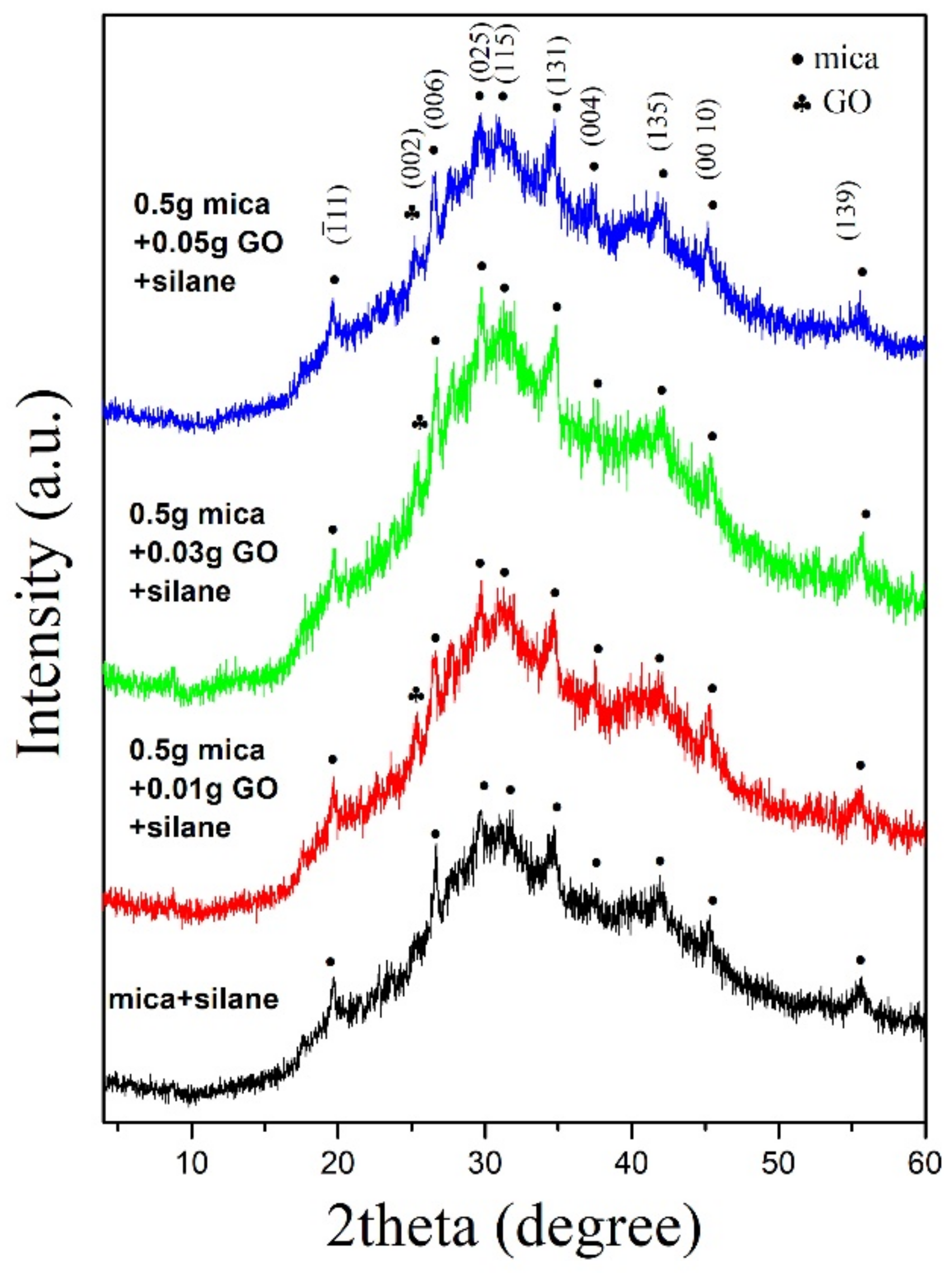
Figure 4 shows XRD patterns of silane-functionalized mica and mica mixed with different proportions of graphene oxide. The XRD pattern of silane-functionalized mica shows low crystallization and therefore, cannot get significant peaks. The results of mica with different ratios graphene oxide both show that (002) peak of graphene oxide in the patterns. Peak intensity is weak and broader, so it can be estimated that the thickness of graphene oxide attached to the mica platelets is very small and cross-linked together well by silane.
In dielectric composite, the energy density is positively related to the surface area of the addition. Table 1 shows the BET surface area of mica before and after functionalization and mixed with graphene oxide. The results show that the surface area reaches 3.18 m2/g after hydrothermal and microwave-assisted exfoliation. The surface area is increased to 16.2 m2/g after the silane functionalization. The surface area increasing may be due to the silane functionalization on the mica surface, which causes mica platelets not to stack and combine firmly, thus expanding the mica’s surface area.
After the mica and graphene oxide are mixed in a ratio of 10:1, the surface area is increased to 22.42 m2/g. Graphene oxide and mica will begin to stack after the solvent is removed. The silane-functionalized mica platelets will be sandwiched with the graphene oxide, creating a gap between the mica platelets, resulting in an increase in the surface area. The graphene oxide has a BET surface area of about 700 m2/g [53], enhancing the mica/ graphene oxide composite’s surface area.
3.2. Graphene Oxide/Mica/Polypropylene Composites
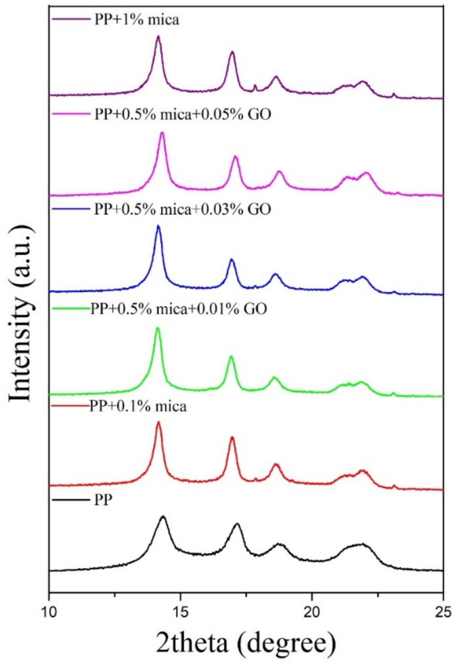
The XRD pattern of the original PP and PP composites films (Figure 5) shows that the effects of different contents of mica and mica/graphene oxide on polypropylene on crystalline properties. For PP film, there are three diffraction peaks, 2θ = 14.1°, 16.9°, 18.5°, corresponding to the crystal face of (110), (040), (130), respectively, which belong to the characteristic diffraction peaks of α-crystalline type. The diffraction peaks at 21.0° and 21.8° combined make independent peaks cannot be separated. For PP + 0.1%mica, PP + 1%mica, PP + 0.5%mica + 0.01%GO, PP + 0.5%mica + 0.03%GO and PP + 0.5%mica + 0.05%GO composite films, two diffraction peaks, 2θ = 21.2° and 21.8° can be found, corresponding to the crystal face of (111) and (131). It can be observed that with the increasing of the content of mica and mica/ graphene oxide, the degree of crystallinity of PP composite increases. Higher crystallization can improve the dielectric strength but it may also increase the dielectric loss of PP composite. The PP composites also exhibit improved thermal stability and higher crystallinity due to that the fillers hinders the mobility of the polymer chains [54].
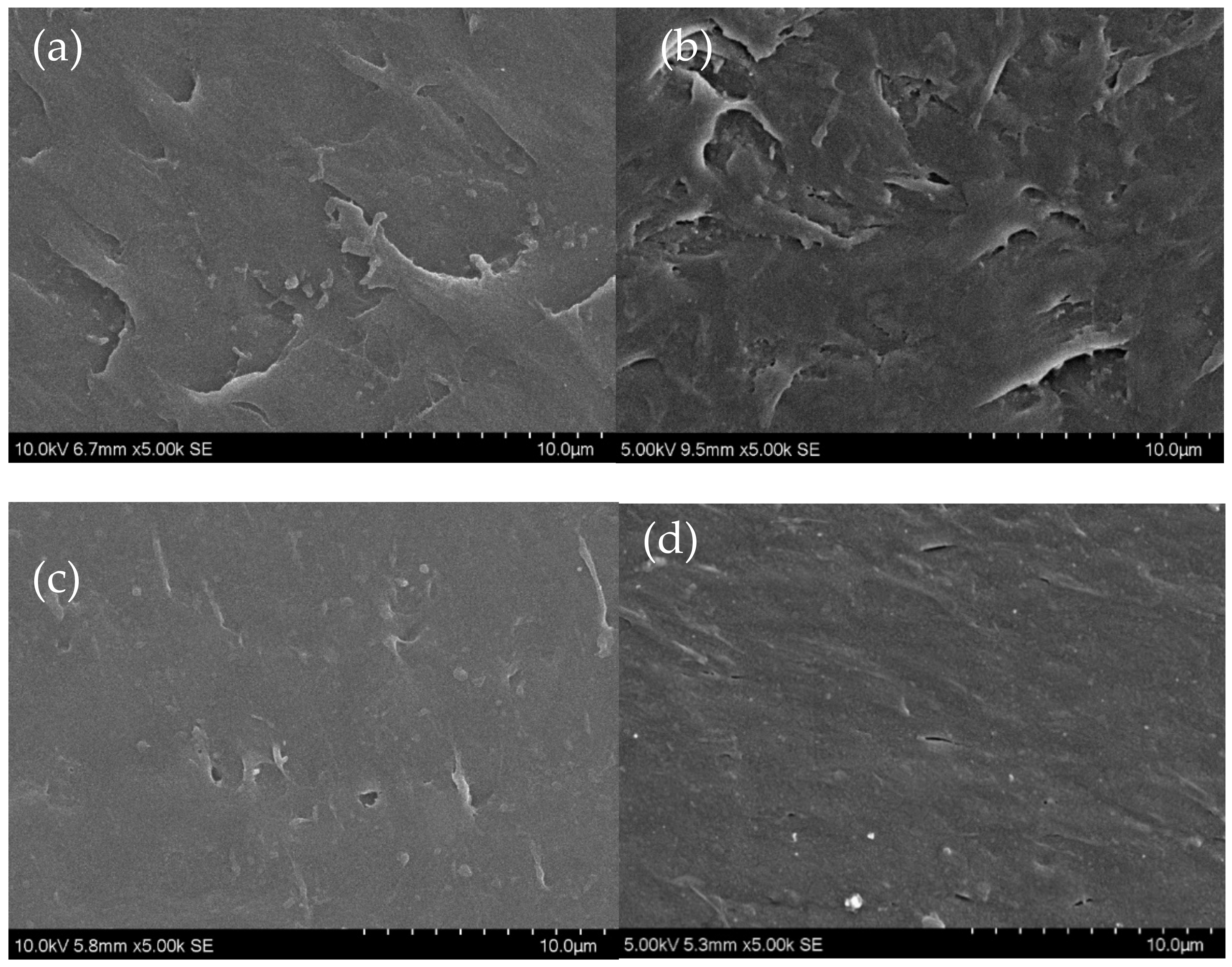
The SEM observation of the hot-pressed PP composite after mixing is shown in Figure 6. Figure 6a shows the surface of the 0.1 wt% mica/polypropylene composite, which shows the flow of the polymer at high temperature after heating and the surface is not smooth. Figure 6b is the surface of 1 wt% mica/polypropylene composite and we can find that the holes at the surface increased significantly. The holes may mainly due to the increase in mica volume at PP composite, increasing polypropylene’s viscosity.
Figure 6c,d was 0.5 wt% mica/0.01 wt% GO/PP and 0.5 wt% mica/0.05 wt% GO/PP SEM observation, it can be seen that the surface appearance is relatively flat after adding graphene oxide, the hole at the surface is reduced. Adding graphene oxide can avoid the increase of PP composite viscosity and small inorganic particles can be observed in the polypropylene substrate.
Figure 7a is the DSC result of PP and PP composite with different mica addition proportions. PP has a heating peak at 160.23 °C while adding different mica content results shows that the heating peak is 159.36 °C. Figure 7b shows DSC results of PP with varying proportions of graphene oxide in the same mica weight ratio. The results show that whether the addition of mica or graphene oxide, the results of DSC did not change much, the main reason is that the amount of addition is so tiny.
Figure 7c is the TGA results of PP and PP composite with different proportions of mica addition, the TGA curve is similar and the remaining weight of PP composites is proportional to the content of mica addition. Figure 7d shows TGA results of PP added different proportions of graphene oxide in the same mica weight ratio and the results show that the TGA curve is almost the same and the more graphene oxide added, the more weight remaining.
3.3. Dielectric Properties of Graphene Oxide/Mica/Polypropylene Composites
Figure 8a shows the relative dielectric constant of PP film with different proportions of mica addition, the relative dielectric constant is measured at AC 1 kHz. The results show that the average relative dielectric constant of PP film is about 2.36, after adding 0.1 wt% mica the result raised to 2.84 and the relative dielectric constant for 1 wt% mica adding is 3.423. The results show that only a small amount of mica adding can significantly increase PP’s dielectric constant value.
Parallel and series models are simplified models to estimate the dielectric properties of a mixture consisting of two different dielectric materials, shown in Equation (2) [55]. The effective dielectric constant “eff” of the mixture can be simply written as
where φ is the volume fractions of two dielectrics respectively, ε is the relative dielectric constant of dielectric and the n is either +1 for a parallel case or −1 for a series case.
The relative dielectric constant of mica and polypropylene from the literature were used to fit Equation (2) to calculate the effective dielectric constant of the composite; we found that we could not correctly match the experiment results. There may be two possible reasons: first, after mica exfoliation and stacked during drying, mica’s density has changed, so it is not possible to know the correct volume ratio. Second, mica’s surface has functionalized by silane, forming an interfacial dielectric between mica and PP, significantly increasing the dielectric constant of mica. It has been reported that there exist interface regions at polymer-filler interfaces in particulate filled polymer composites [56]. The interface region consists of polymer molecules which are bonded at the filler particle interface giving rise to unique electrical and physical properties [8].
The parallel and series model is derived from experimental data and does not represent all the components’ physical principles discussed. graphene oxide/mica added in this study is different from the fillers added by the previous study, resulting in the inability to use this model to infer the relationship between the addition and the composite’s dielectric constant.
Chemical coupling agents (VTS) and surfactants (PPgMA) are used to enhance the compatibility between the polypropylene and dispersed mica/graphene oxide. Thus, in a PP-mica-graphene oxide interface region, polymer molecules bonded to the graphene oxide and mica surface, creating a composite filler with different electrical characteristics from constituent states. We can assume that the PP/mica composite’s dielectric constant is significantly improved by interfacial capacitance.
Dielectric material with higher dielectric loss will be easier to cause the dissipation of energy by generating waste heat and also decreases the discharged energy density and the charge/discharge efficiency of the capacitors. Therefore, only increasing the dielectric constant and reducing the dielectric loss of dielectric materials can effectively improve the capacitor’s performance.
Generally speaking, in dielectric polymer composites, with the increase of dielectric filler, the dielectric loss of composite will also raise due to the interface between polymer and filler. In this study, the dielectric loss did not increase much as the additions increased; this may be due to the minimal amount of modified mica added.
Figure 8b shows relative dielectric constant and dielectric loss of 0.5 wt% mica with different proportions of graphene oxide added to the PP matrix. The results show that the relative dielectric constant increases with the addition of graphene oxide. After adding 0.05 wt% graphene oxide, the relative dielectric constant is 3.753, up 60% from PP and the dielectric loss remains unchanged.
The amount of mica and mica/ graphene oxide added in this study is very tiny. Such a low amount of addition can improve relative dielectric constant and retain the low dielectric loss of polypropylene. Mica and graphene oxide composite platelets can be considered high dielectric additions. These silane-functionalized platelets and polypropylene connected to form more interfacial layers enhance the dielectric constant of the composite.
The main reason for testing the dielectric strength of mica/graphene oxide/polypropylene composites following the ASTM D149 standard is that the material’s overall dielectric strength can be obtained not just perfect areas without any defect been tested.
Because we cannot avoid generating some defects during polymer capacitors’ production, these defects will cause a significant reduction in dielectric strength, especially for composite polymer capacitors. Performance-enhancing fillers will import more defects into polymer dielectric film, so to test the overall dielectric strength to meet the real needs is more proper. For polypropylene, the dielectric strength obtained by ASTM D149 is approximately 23.6 kV/mm [57].
In addition to the dielectric constant, breakdown strength is also an important parameter that determines polymer composites’ energy density. The maximum energy storage density (wmax: Jm−3) of linear dielectrics is related to breakdown strength as follows [55,58],
where Eb is the breakdown strength of the medium, the material’s breakdown strength is the maximum electric field that can be applied to a dielectric without making it conducting. It can be known from the equation that increasing the value of relative dielectric constant and dielectric strength can improve the theoretical energy density of dielectrics.
Fillers with an excellent dielectric constant are necessary to improve composites’ energy density but it should not lower breakdown strength at the same time. Moreover, a large difference in dielectric constants between fillers and polymer matrix results in inhomogeneity in the electric fields of polymers, which may lower the breakdown strength and energy density.
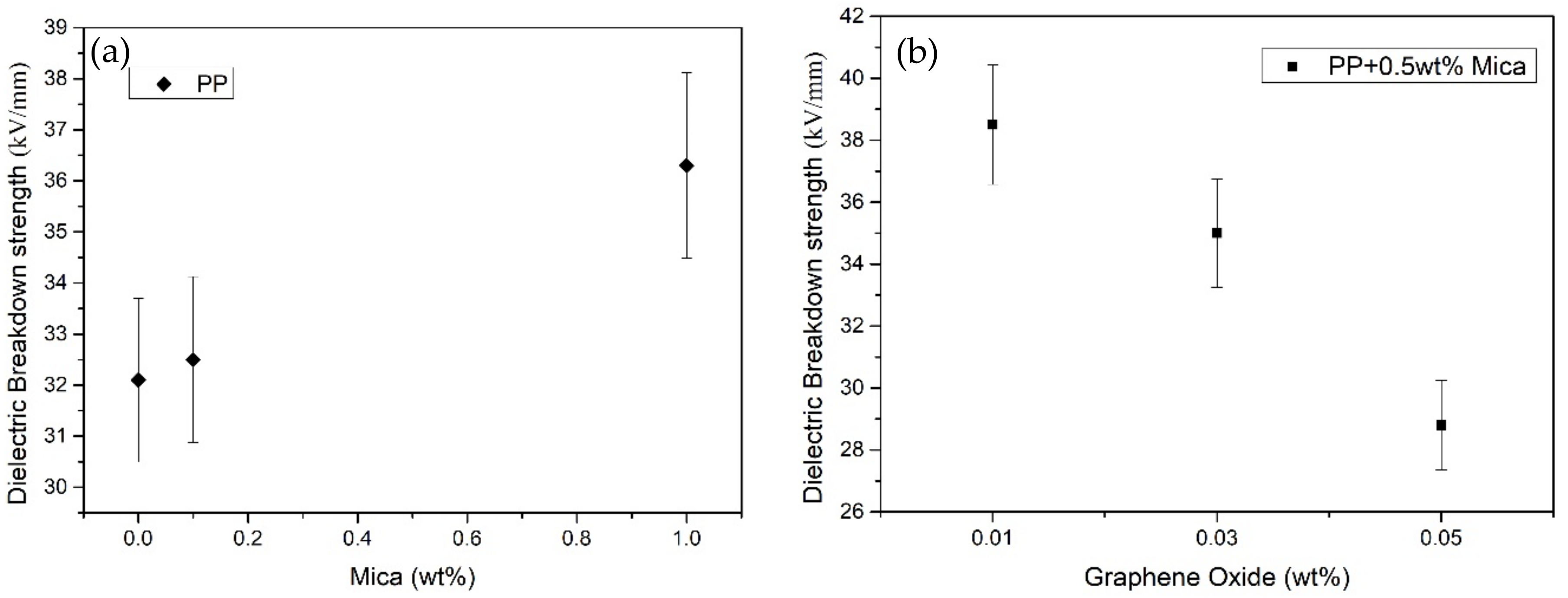
Table 2 shows the sample size and dielectric strength of PP with different proportions of mica and graphene oxide and Figure 9 shows the dielectric strength comparison of all samples. The results show that the small number of mica platelets can increase the dielectric strength. With the increase in the amount of mica addition, the dielectric strength also gradually increases. The flat plate structure of mica platelets can increase dielectric strength, mainly because it increases the electrically conductive path’s distance. 0.5% mica/0.01% GO/PP achieve the highest dielectric strength value 38.5 KV/mm, however, with the increase of graphene oxide, dielectric strength has decreased significantly.
For a composite, the electric field is not uniform under an electric field and its distribution depends on each ingredient’s dielectric property. Although mica/graphene oxide platelets’ addition can significantly improve dielectric constants also help enhance the density of electrical energy. Still, the inhomogeneity of the electric field in the polymers is more and more serious. Furthermore, it is possible to peel off graphene oxide from the mica during the twin-screw mixing and mixed graphene oxide into the polypropylene matrix, increasing interface defects in the composite and increased conductivity. These defects may make a decrease in the dielectric strength of the dielectric polymer film.
Results obtained by ASTM D149 method can seldom be used directly to determine the dielectric behavior of a material in an actual application. In most cases, these results need to be evaluated by comparing the test results with other materials. It can be found that the addition of mica and a small amount of graphene oxide increases the dielectric strength of polypropylene compared to the result of PP raw materials.
3.4. Tensile Test of Graphene Oxide/Mica/Polypropylene Films
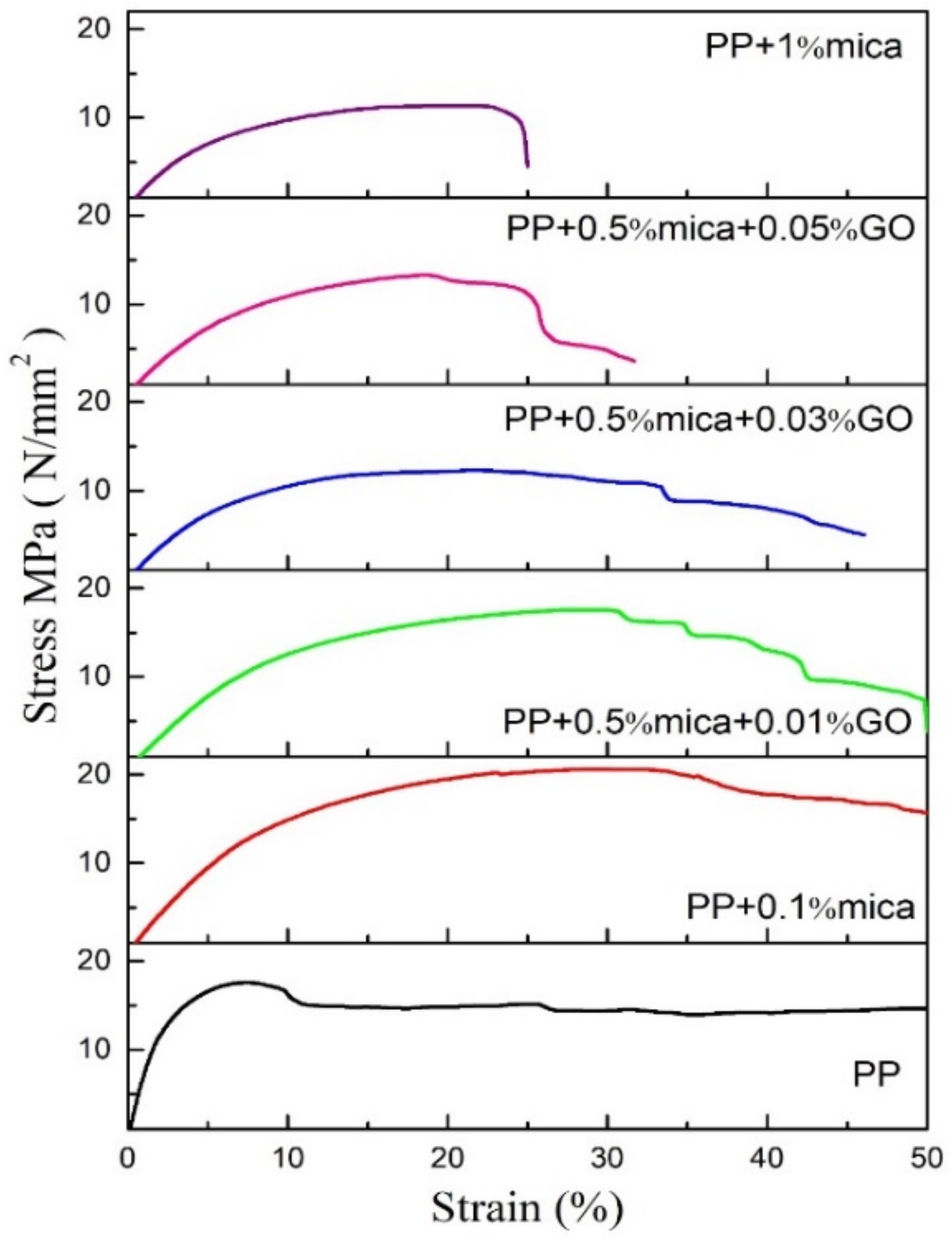
In addition to dielectric properties, mechanical properties are also a critical factor for polymer capacitors, as they affect the yield and reliability of the final product. The engineering tensile stress-strain curves of PP, mica/PP and mica/graphene oxide/PP films are shown in Figure 10, from which the elongation of polypropylene is over 50% and the ultimate tensile strength (UTS) is 17.8 MPa.
The experimental data show that the tiny amount of mica mixed with PP will increase the PP composite’s tensile strength but the elongation is significantly reduced. The tensile elongation of 0.1% mica/PP can reach 50% but 1% mica/PP only 25% left.
Adding a small number of fillers in the matrix increases polypropylene’s mechanical properties, whether tensile strength or elongation. As the number of fillers increases, the mechanical properties begin to decrease significantly. With the rise of inorganic brittle mica in polypropylene resulting in a decrease in tensile elongation. Dual screw mixing was used to stir mica, graphene oxide and PP, that will cause layered mica and graphene oxide de-layering and produce defects in polypropylene matrix and these internal defects make the tensile strength decreased.
When mica and graphene oxide disperse into the PP matrix separately, it can improve dielectric constant but often results in an augmentation in dielectric loss and processing performance reduction. Adding a small amount of mica/graphene oxide platelets to polypropylene seems to get the optimal results. The reasons for this are not fully understood and more research is needed.
4. Conclusions
The addition of a high permittivity non-conducting material to polymer capacitor could increase the capacitor’s energy density and enhances the ability to resist the high electric field. This study successfully prepared mica/graphene oxide composite platelet and mixed it with polypropylene to produce mica/graphene oxide/polypropylene dielectric film. The experimental results confirmed that a small amount of addition (less than 1 wt%) could enhance the relative dielectric constant of polypropylene, without causing an increase in dielectric loss. In a specific addition ratio, can also improve dielectric strength.
The increase of the amount of graphene oxide benefits to enhancing dielectric constants is more significant than that of mica. Still, more graphene oxide will cause a decrease in dielectric strength and mechanical properties. Too many additives will increase the composite’s dielectric loss, decrease the dielectric strength and mechanical properties. The functional groups on the surface of the graphene oxide can avoid reducing the influence of the additives. The two-dimensional planar mica/graphene oxides can increase the electrically conductive pathway’s length, thereby enhancing the ability to resist high electric fields. This study confirmed that adding a small amount of mica/graphene oxide composite can increase the energy density while maintaining the other electrical advantages of polypropylene and maintaining sufficient mechanical processing performance.
Author Contributions
Conceptualization, C.-Y.L.; methodology, C.-Y.L.; data curation, C.-W.C.; writing—original draft preparation, C.-Y.L. All authors have read and agreed to the published version of the manuscript.
Funding
This research was funded by National Chung-Shan Institute of Science & Technology, Taiwan. Grant number: XV07014P152PE-CS.
Acknowledgments
Authors acknowledge the researchers in National Chung-Shan Institute of Science & Technology Chien-Chih Kung for the help in experiment and discussion.
Conflicts of Interest
The authors declare no conflict of interest.
References
- Borchardt, J.; Alexander, J.; Slenes, K.; De La Fuente, R. Ceramic-polymer composite for high energy density capacitors. In Proceedings of the 16th IEEE International Pulsed Power Conference, Albuquerque, NM, USA, 17–22 June 2007; Volume 1, pp. 294–297. [Google Scholar]
- Tummala, R.R.; Laskar, J. Gigabit Wireless: System-on-a-Package Technology. Proc. IEEE 2004, 92, 376–387. [Google Scholar] [CrossRef]
- Gray, F.M.; Armand, M. Energy Storage Systems for Electronics; Gordon and Breach Science Publications: Amsterdam, The Netherlands, 2000. [Google Scholar]
- Karden, E.; Ploumen, S.; Fricke, B.; Miller, T.; Snyder, K. Energy storage devices for future hybrid electric vehicles. J. Power Sources 2007, 168, 2–11. [Google Scholar] [CrossRef]
- Fiedziuszko, S.; Hunter, I.; Itoh, T.; Kobayashi, Y.; Nishikawa, T.; Stitzer, S.; Wakino, K. Dielectric materials, devices, and circuits. IEEE Trans. Microw. Theory Tech. 2002, 50, 706–720. [Google Scholar] [CrossRef]
- Jillek, W.; Yung, W.K.C. Embedded components in printed circuit boards: A processing technology review. Int. J. Adv. Manuf. Technol. 2004, 25, 350–360. [Google Scholar] [CrossRef]
- Yoon, J.-R.; Han, J.-W.; Lee, K.-M. Dielectric Properties of Polymer-ceramic Composites for Embedded Capacitors. Trans. Electr. Electron. Mater. 2009, 10, 116–120. [Google Scholar] [CrossRef] [Green Version]
- Sebastian, M.T.; Jantunen, H. Polymer–ceramic composites of 0-3 connectivity for circuits in electronics: A review. Int. J. Appl. Ceram. Technol. 2010, 7, 415–434. [Google Scholar] [CrossRef]
- Newnham, R.; Skinner, D.; Cross, L. Connectivity and piezoelectric-pyroelectric composites. Mater. Res. Bull. 1978, 13, 525–536. [Google Scholar] [CrossRef]
- Skinner, D.; Newnham, R.; Cross, L. Flexible composite transducers. Mater. Res. Bull. 1978, 13, 599–607. [Google Scholar] [CrossRef]
- Jayasundere, N.; Smith, B.V.; Dunn, J.R. Piezoelectric constant for binary piezoelectric 0-3 connectivity composites and the effect of mixed connectivity. J. Appl. Phys. 1994, 76, 2993–2998. [Google Scholar] [CrossRef]
- Wong, C.K.; Poon, Y.M.; Shin, F.G. Explicit formulas for effective piezoelectric coefficients of ferroelectric 0-3 composites. J. Appl. Phys. 2001, 90, 4690–4700. [Google Scholar] [CrossRef] [Green Version]
- Pilgrim, S.; Newnham, R. 3:0: A new composite connectivity. Mater. Res. Bull. 1986, 21, 1447–1454. [Google Scholar] [CrossRef]
- Nan, C.-W.; Shen, Y.; Ma, J. Physical Properties of Composites Near Percolation. Annu. Rev. Mater. Res. 2010, 40, 131–151. [Google Scholar] [CrossRef]
- Newnham, R.E. Composite electroceramics. Ferroelectrics 1986, 68, 1–32. [Google Scholar] [CrossRef]
- Fang, D.-N.; Soh, A.K.; Li, C.-Q.; Jiang, B. Nonlinear behavior of 0-3 type ferroelectric composites with polymer matrices. J. Mater. Sci. 2001, 36, 5281–5288. [Google Scholar] [CrossRef]
- Komarneni, S. Nanocomposites. J. Mater. Chem. 1992, 2, 1219–1230. [Google Scholar] [CrossRef]
- Garboczi, E.J.; Snyder, K.A.; Douglas, J.F.; Thorpe, M.F. Geometrical percolation threshold of overlapping ellipsoids. Phys. Rev. E 1995, 52, 819–828. [Google Scholar] [CrossRef] [PubMed] [Green Version]
- Toker, D.; Azulay, D.; Shimoni, N.; Balberg, I.; Millo, O. Tunneling and percolation in metal-insulator composite materials. Phys. Rev. B 2003, 68, 041403. [Google Scholar] [CrossRef] [Green Version]
- Shen, Y.; Yue, Z.; Li, M.; Nan, C.-W. Enhanced Initial Permeability and Dielectric Constant in a Double- Percolating Ni0.3Zn0.7Fe1.95O4-Ni- Polymer Composite. Adv. Funct. Mater. 2005, 15, 1100–1103. [Google Scholar] [CrossRef]
- Yang, J.; Zhu, X.; Wang, H.; Wang, X.; Hao, C.; Fan, R.; Shi, Z. Achieving excellent dielectric performance in polymer composites with ultralow filler loadings via construct-ing hollow-structured filler frameworks. Compos. Part A Appl. Sci. Manuf. 2020, 131, 105814. [Google Scholar] [CrossRef]
- Mo, H.; Wang, G.; Liu, F.; Jiang, P. The influence of the interface between mica and epoxy matrix on properties of epoxy-based dielectric mate-rials with high thermal conductivity and low dielectric loss. RSC Adv. 2016, 6, 83163–83174. [Google Scholar] [CrossRef]
- Rabuffi, M.; Picci, G. Status quo and future prospects for metallized polypropylene energy storage capacitors. IEEE Trans. Plasma Sci. 2002, 30, 1939–1942. [Google Scholar] [CrossRef]
- Zheng, M.S.; Zheng, Y.T.; Zha, J.W.; Yang, Y.; Han, P.; Wen, Y.Q.; Dang, Z.M. Improved dielectric, tensile and energy storage properties of surface rubberized BaTiO3/polypropylene nanocomposites. Nano Energy 2018, 48, 144–151. [Google Scholar] [CrossRef]
- Yao, J.; Hu, L.; Zhou, M.; You, F.; Jiang, X.; Gao, L.; Wang, Q.; Sun, Z.; Wang, J. Synergistic enhancement of thermal conductivity and dielectric properties in Al2O3/BaTiO3/PP composites. Materials 2018, 11, 1536. [Google Scholar] [CrossRef] [PubMed] [Green Version]
- Alig, I.; Lellinger, D.; Dudkin, S.M.; Pötschke, P. Conductivity spectroscopy on melt processed polypropylene–multiwalled carbon nanotube composites: Re-covery after shear and crystallization. Polymer 2007, 48, 1020–1029. [Google Scholar] [CrossRef]
- Xu, H.P.; Dang, Z.M.; Jiang, M.J.; Yao, S.H.; Bai, J. Enhanced dielectric properties and positive temperature coefficient effect in the binary polymer composites with surface modified carbon black. J. Mater. Chem. 2008, 18, 229–234. [Google Scholar] [CrossRef]
- Motori, A.; Montanari, G.C.; Saccani, A.; Patuelli, F. Electrical conductivity and polarization processes in nanocomposites based on isotactic polypropylene and modified synthetic clay. J. Polym. Sci. Part B Polym. Phys. 2007, 45, 705–713. [Google Scholar] [CrossRef]
- Yu, C.-R.; Wu, D.-M.; Liu, Y.; Qiao, H.; Yu, Z.-Z.; Dasari, A.; Du, X.; Mai, Y.-W. Electrical and dielectric properties of polypropylene nanocomposites based on carbon nanotubes and barium titanate nanoparticles. Compos. Sci. Technol. 2011, 71, 1706–1712. [Google Scholar] [CrossRef]
- Li, Z.; Fredin, L.A.; Tewari, P.; DiBenedetto, S.A.; Lanagan, M.T.; Ratner, M.A.; Marks, T.J. In Situ catalytic encapsulation of core-shell nanoparticles having variable shell thickness: Dielectric and energy storage properties of high-permittivity metal oxide nanocomposites. Chem. Mater. 2010, 22, 5154–5164. [Google Scholar] [CrossRef]
- Takala, M.; Ranta, H.; Nevalainen, P.; Pakonen, P.; Pelto, J.; Karttunen, M.; Virtanen, S.; Koivu, V.; Pettersson, M.; Sonerud, B.; et al. Dielectric properties and partial discharge endurance of polypropylene-silica nanocomposite. IEEE Trans. Dielectr. Electr. Insul. 2010, 17, 1259–1267. [Google Scholar] [CrossRef]
- Li, Y.; Zhu, J.; Wei, S.; Ryu, J.; Sun, L.; Guo, Z. Poly(propylene)/Graphene Nanoplatelet Nanocomposites: Melt Rheological Behavior and Thermal, Electrical, and Electronic Properties. Macromol. Chem. Phys. 2011, 212, 1951–1959. [Google Scholar] [CrossRef]
- Sui, G.; Jana, S.; Zhong, W.; Fuqua, M.; Ulven, C. Dielectric properties and conductivity of carbon nanofiber/semi-crystalline polymer composites. Acta Mater. 2008, 56, 2381–2388. [Google Scholar] [CrossRef]
- Wan, Y.J.; Yang, W.H.; Yu, S.H.; Sun, R.; Wong, C.P.; Liao, W.H. Covalent polymer functionalization of graphene for improved dielectric properties and thermal stability of epoxy composites. Compos. Sci. Technol. 2016, 122, 27–35. [Google Scholar] [CrossRef]
- Li, M.; Deng, Y.; Wang, Y.; Zhang, Y.; Bai, J. High dielectric properties in a three-phase polymer composite induced by a parallel structure. Mater. Chem. Phys. 2013, 139, 865–870. [Google Scholar] [CrossRef]
- Yang, C.; Lin, Y.; Nan, C. Modified carbon nanotube composites with high dielectric constant, low dielectric loss and large energy density. Carbon 2009, 47, 1096–1101. [Google Scholar] [CrossRef]
- Lerf, A.; He, H.; Forster, M.; Klinowski, J. Structure of Graphite Oxide Revisited. J. Phys. Chem. B 1998, 102, 4477–4482. [Google Scholar] [CrossRef]
- Zhi, X.; Mao, Y.; Yu, Z.; Wen, S.; Li, Y.; Zhang, L.; Chan, T.W.; Liu, L. γ-Aminopropyl triethoxysilane functionalized graphene oxide for composites with high dielectric constant and low dielectric loss. Compos. Part A 2015, 76, 194–202. [Google Scholar] [CrossRef]
- Yang, X.; Tu, Y.; Li, L.; Shang, S.; Tao, X.-M. Well-Dispersed Chitosan/Graphene Oxide Nanocomposites. ACS Appl. Mater. Interfaces 2010, 2, 1707–1713. [Google Scholar] [CrossRef] [PubMed]
- Medhekar, N.V.; Ramasubramaniam, A.; Ruoff, R.S.; Shenoy, V.B. Hydrogen bond networks in graphene oxide composite paper: Structure and mechanical properties. ACS Nano 2010, 4, 2300–2306. [Google Scholar] [CrossRef]
- Zokaie, M.; Foroutan, M. Comparative study on confinement effects of graphene and graphene oxide on structure and dynamics of water. RSC Adv. 2015, 5, 39330–39341. [Google Scholar] [CrossRef]
- Zhu, Y.; Murali, S.; Cai, W.; Li, X.; Suk, J.W.; Potts, J.R.; Ruoff, R.S. Graphene and Graphene Oxide: Synthesis, Properties, and Applications. Adv. Mater. 2010, 22, 3906–3924. [Google Scholar] [CrossRef]
- Zhu, Y.; James, D.K.; Tour, J.M. New routes to graphene, graphene oxide and their related applications. Adv. Mater. 2012, 24, 4924–4955. [Google Scholar] [CrossRef]
- Dreyer, D.R.; Todd, A.D.; Bielawski, C.W. Harnessing the chemistry of graphene oxide. Chem. Soc. Rev. 2014, 43, 5288–5301. [Google Scholar] [CrossRef]
- Yousefi, N.; Sun, X.; Lin, X.; Shen, X.; Jia, J.; Zhang, B.; Tang, B.; Chan, M.; Kim, J.-K. Highly Aligned Graphene/Polymer Nanocomposites with Excellent Dielectric Properties for High-Performance Electromagnetic Interference Shielding. Adv. Mater. 2014, 26, 5480–5487. [Google Scholar] [CrossRef]
- Wu, Y.; Lin, X.; Shen, X.; Sun, X.; Liu, X.; Wang, Z. Exceptional dielectric properties of chlorine-doped graphene oxide/poly (vinylidene fluoride). Nanocompos. Carbon 2015, 89, 102–112. [Google Scholar] [CrossRef]
- Wan, Y.-J.; Gong, L.-X.; Tang, L.-C.; Wu, L.-B.; Jiang, J.-X. Mechanical properties of epoxy composites filled with silane-functionalized graphene oxide. Compos. Part A Appl. Sci. Manuf. 2014, 64, 79–89. [Google Scholar] [CrossRef]
- Shen, J.; Hu, Y.; Shi, M.; Li, N.; Ma, H.; Ye, M. One Step Synthesis of Graphene Oxide–Magnetic Nanoparticle Composite. J. Phys. Chem. C 2010, 114, 1498–1503. [Google Scholar] [CrossRef]
- Nam, W.H.; Kim, B.B.; Seo, S.G.; Lim, Y.S.; Kim, J.Y.; Seo, W.S.; Choi, W.K.; Park, H.H.; Lee, J.Y. Structurally nanocrystalline-electrically single crystalline zno-reduced graphene oxide composites. Nano Lett. 2014, 14, 5104–5109. [Google Scholar] [CrossRef]
- Standard, ASTM. D149-09, Standard Test Method for Dielectric Breakdown Voltage and Dielectric Strength of Solid Electrical Insulating Materials at Commercial Power Frequencies; Research Report; ASTM International: West Conshohocken, PA, USA, 2009.
- Li, H.; Ren, L.; Zhou, Y.; Yao, B.; Wang, Q. Recent progress in polymer dielectrics containing boron nitride nanosheets for high energy density capacitors. High Volt. 2020, 5, 365–376. [Google Scholar] [CrossRef]
- Mendoza-Sánchez, B.; Gogotsi, Y. Synthesis of Two-Dimensional Materials for Capacitive Energy Storage. Adv. Mater. 2016, 28, 6104–6135. [Google Scholar] [CrossRef]
- Mohan, V.B.; Jayaraman, K.; Bhattacharyya, D. Brunauer–Emmett–Teller (BET) specific surface area analysis of different graphene materials: A comparison to their structural regularity and electrical properties. Solid State Commun. 2020, 320, 114004. [Google Scholar] [CrossRef]
- Zhang, C.; Dang, Z.-M.; Yan, H.-D.; Li, W.-K.; Dang, Z.-M. High improvement in trap level density and direct current breakdown strength of block polypropylene by doping with a β-nucleating agent. Appl. Phys. Lett. 2018, 112, 091902. [Google Scholar] [CrossRef]
- Thakur, V.K.; Gupta, R.K. Recent Progress on Ferroelectric Polymer-Based Nanocomposites for High Energy Density Capacitors: Synthesis, Dielectric Properties, and Future Aspects. Chem. Rev. 2016, 116, 4260–4317. [Google Scholar] [CrossRef]
- Todd, M.G.; Shi, F.G. Characterizing the interface dielectric constant of polymer composite materials: Effect of chemical coupling agents. J. Appl. Phys. 2003, 94, 4551–4557. [Google Scholar] [CrossRef]
- Shugg, W. Handbook of electrical and electronic insulating materials, second edition. IEEE Electr. Insul. Mag. 1996, 12, 40. [Google Scholar] [CrossRef]
- Dang, Z.-M.; Yuan, J.-K.; Zha, J.-W.; Zhou, T.; Li, S.-T.; Hu, G.-H. Fundamentals, processes and applications of high-permittivity polymer–matrix composites. Prog. Mater. Sci. 2012, 57, 660–723. [Google Scholar] [CrossRef]
Figure 1.
Mica/graphene oxide/polypropylene composite production process.

Figure 2.
(a) Scanning electron microscopy (SEM) image of mica after microwave process (b) transmission electron microscopy (TEM) image of mica after the centrifugal procedure (c) SEM image of silane-functionalized mica platelet (d) TEM image of silane-functionalized mica/graphene oxide platelet.
Figure 2.
(a) Scanning electron microscopy (SEM) image of mica after microwave process (b) transmission electron microscopy (TEM) image of mica after the centrifugal procedure (c) SEM image of silane-functionalized mica platelet (d) TEM image of silane-functionalized mica/graphene oxide platelet.


Figure 3.
Fourier transform infrared (FTIR) spectra of mica and mica/graphene oxide before and after functionalization with silane.
Figure 3.
Fourier transform infrared (FTIR) spectra of mica and mica/graphene oxide before and after functionalization with silane.

Figure 4.
X-ray diffraction (XRD) patterns of silane-functionalized mica and mica/graphene oxide.

Figure 5.
The X-ray diffraction patterns of polypropylene, mica/polypropylene and graphene oxide/mica/polypropylene films.
Figure 5.
The X-ray diffraction patterns of polypropylene, mica/polypropylene and graphene oxide/mica/polypropylene films.

Figure 6.
(a) The surface of the 0.1 wt% mica/polypropylene composite, (b) the surface of the 1 wt% mica/polypropylene composite (c) 0.5 wt% mica/0.01 wt% graphene oxide (GO)/polypropylene (PP) and (d) 0.5 wt% mica/0.05 wt% GO/PP SEM observation.
Figure 6.
(a) The surface of the 0.1 wt% mica/polypropylene composite, (b) the surface of the 1 wt% mica/polypropylene composite (c) 0.5 wt% mica/0.01 wt% graphene oxide (GO)/polypropylene (PP) and (d) 0.5 wt% mica/0.05 wt% GO/PP SEM observation.

Figure 7.
Differential scanning calorimetry (DSC) heating curves of (a) polypropylene (PP) and the PP/mica composites. (b) PP/mica/graphene oxide composites. And Thermogravimetric analysis (TGA) curves of (c) polypropylene (PP) and the PP/mica composites. (d) PP/mica/graphene oxide composites.
Figure 7.
Differential scanning calorimetry (DSC) heating curves of (a) polypropylene (PP) and the PP/mica composites. (b) PP/mica/graphene oxide composites. And Thermogravimetric analysis (TGA) curves of (c) polypropylene (PP) and the PP/mica composites. (d) PP/mica/graphene oxide composites.

Figure 8.
(a) the relative dielectric constant of PP film with different proportions of mica addition, (b) shows the relative dielectric constant and dielectric loss of 0.5 wt% mica with varying proportions of graphene oxide added to the PP matrix.
Figure 8.
(a) the relative dielectric constant of PP film with different proportions of mica addition, (b) shows the relative dielectric constant and dielectric loss of 0.5 wt% mica with varying proportions of graphene oxide added to the PP matrix.


Figure 9.
Dielectric strength comparison of all samples (a) the PP film with different proportions of mica addition, (b) 0.5 wt% mica with varying proportions of graphene oxide added to the polypropylene.
Figure 9.
Dielectric strength comparison of all samples (a) the PP film with different proportions of mica addition, (b) 0.5 wt% mica with varying proportions of graphene oxide added to the polypropylene.

Figure 10.
Tensile stress-strain curves of polypropylene, mica/polypropylene and graphene oxide/mica/polypropylene films.
Figure 10.
Tensile stress-strain curves of polypropylene, mica/polypropylene and graphene oxide/mica/polypropylene films.


Table 1.
Brunauer-Emmett-Teller (BET) surface area of mica before and after functionalization and mixed with graphene oxide.
Table 1.
Brunauer-Emmett-Teller (BET) surface area of mica before and after functionalization and mixed with graphene oxide.
| Sample | BET Surface Area(m2/g) |
|---|---|
| Mica | 3.18 |
| Mica+silane | 16.2 |
| 0.5% mica + 0.05% GO + silane | 22.42 |
Table 2.
Dielectric strength of PP with different proportions of mica and graphene oxide.
| Sample | Area (cm2) | Thickness (mm) | Breakdown Voltage (KV) | Dielectric Strength (KV/mm) |
|---|---|---|---|---|
| PP | 133.0 | 1.25 | 40 | 32.1 |
| 0.1% mica/PP | 133.2 | 1.18 | 38.4 | 32.5 |
| 1% mica/PP | 133.0 | 1.18 | 43.2 | 36.3 |
| 0.5% mica/0.01% GO/PP | 133.4 | 1.17 | 45.1 | 38.5 |
| 0.5% mica/0.03% GO/PP | 133.3 | 1.19 | 41.7 | 35 |
| 0.5% mica/0.05% GO/PP | 133.3 | 1.13 | 32.6 | 28.8 |
Publisher’s Note: MDPI stays neutral with regard to jurisdictional claims in published maps and institutional affiliations. |
© 2021 by the authors. Licensee MDPI, Basel, Switzerland. This article is an open access article distributed under the terms and conditions of the Creative Commons Attribution (CC BY) license (http://creativecommons.org/licenses/by/4.0/).
Share and Cite
MDPI and ACS Style
Lee, C.-Y.; Chang, C.-W. Dielectric Constant Enhancement with Low Dielectric Loss Growth in Graphene Oxide/Mica/Polypropylene Composites. J. Compos. Sci. 2021, 5, 52. https://0-doi-org.brum.beds.ac.uk/10.3390/jcs5020052
AMA Style
Lee C-Y, Chang C-W. Dielectric Constant Enhancement with Low Dielectric Loss Growth in Graphene Oxide/Mica/Polypropylene Composites. Journal of Composites Science. 2021; 5(2):52. https://0-doi-org.brum.beds.ac.uk/10.3390/jcs5020052
Chicago/Turabian StyleLee, Chao-Yu, and Chia-Wei Chang. 2021. "Dielectric Constant Enhancement with Low Dielectric Loss Growth in Graphene Oxide/Mica/Polypropylene Composites" Journal of Composites Science 5, no. 2: 52. https://0-doi-org.brum.beds.ac.uk/10.3390/jcs5020052