
Multiscale Toughening of Composites with Carbon Nanotubes—Continuous Multiscale Reinforcement New Concept

Abstract
:1. Introduction
- (1)
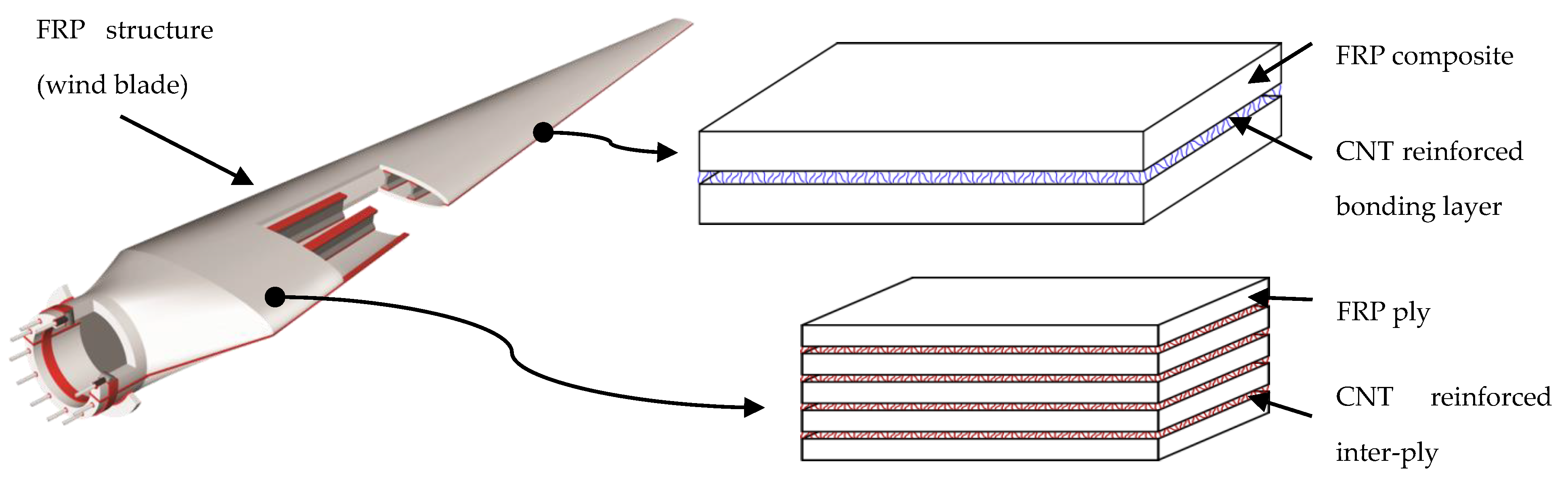
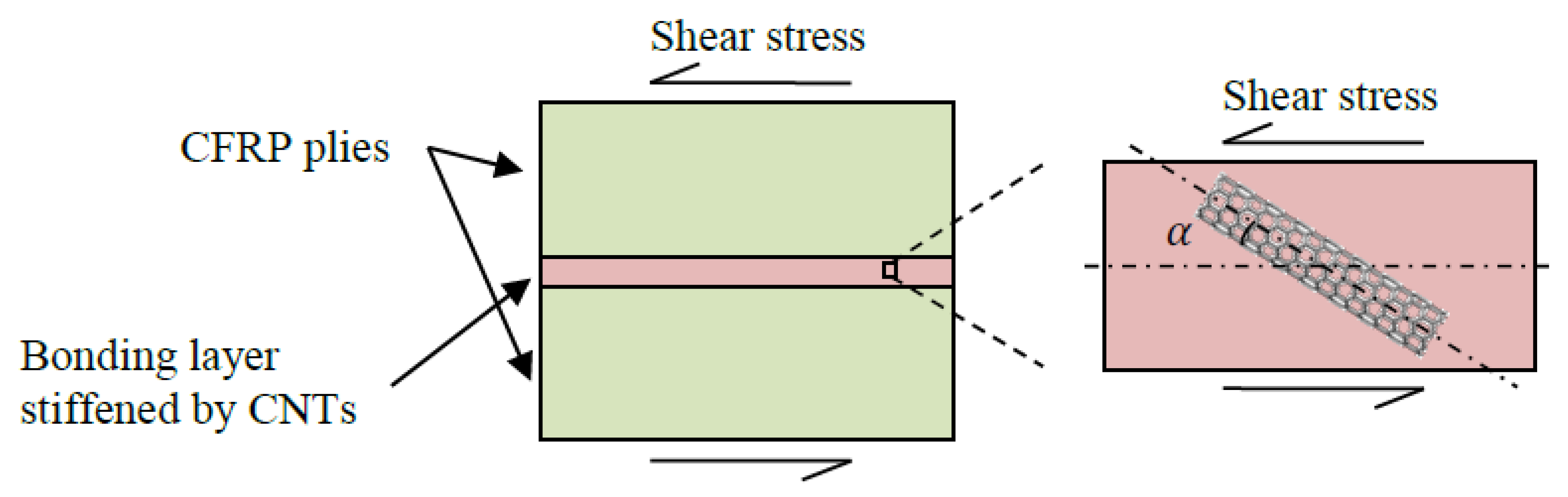
- Increasing the stiffness of inter-plies by CNT-reinforced resin. Moreover, if CNT orientation can be optimized, through reinforcement mechanisms (crack-bridging and pull-out), delamination strength will be enhanced.
- (2)
- Reinforcement of composite bonding joints by CNT-reinforced resin, which will result in higher bonding strength, and thus improve joints’ toughness.
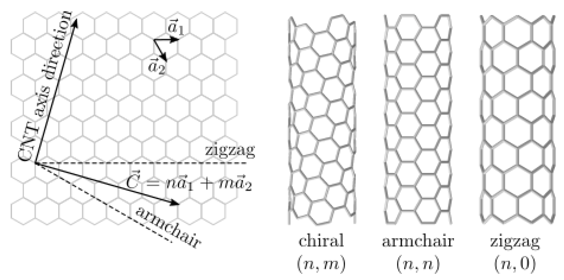
2. Atomic Structure of CNTs
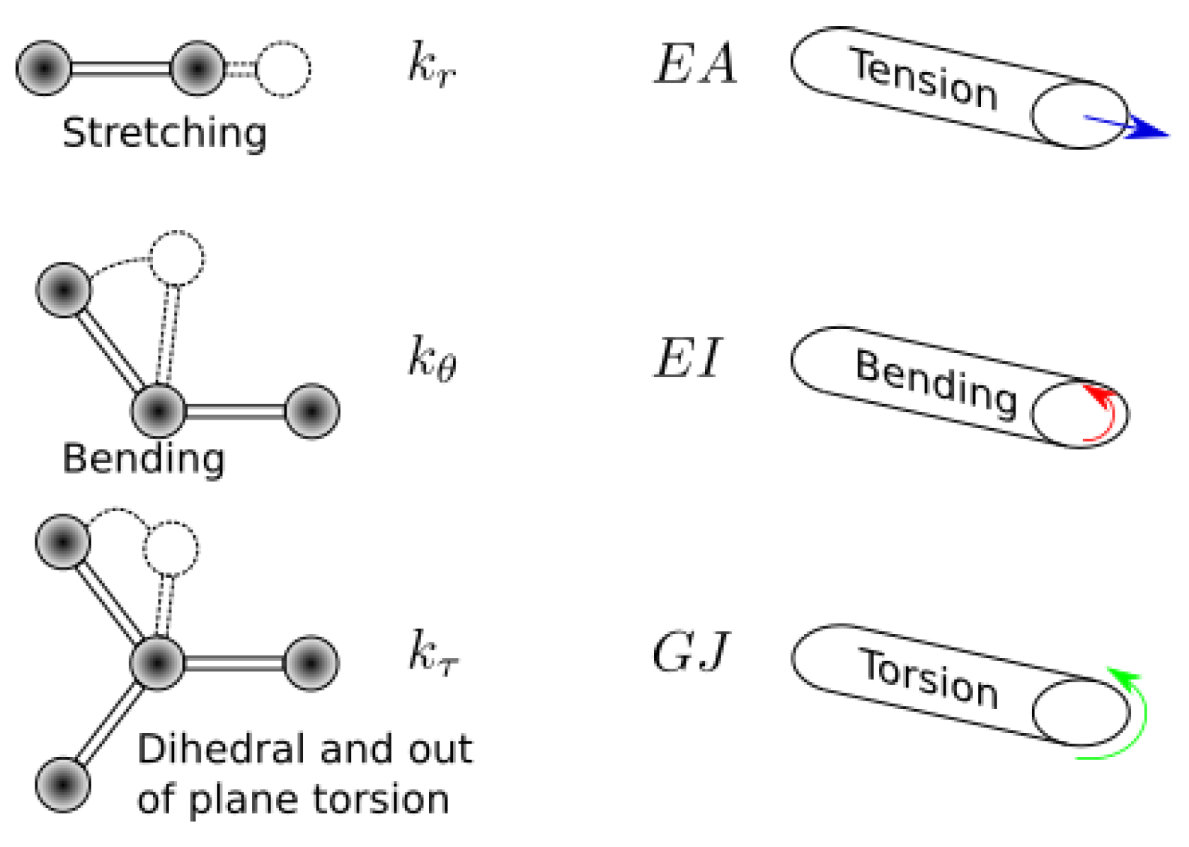
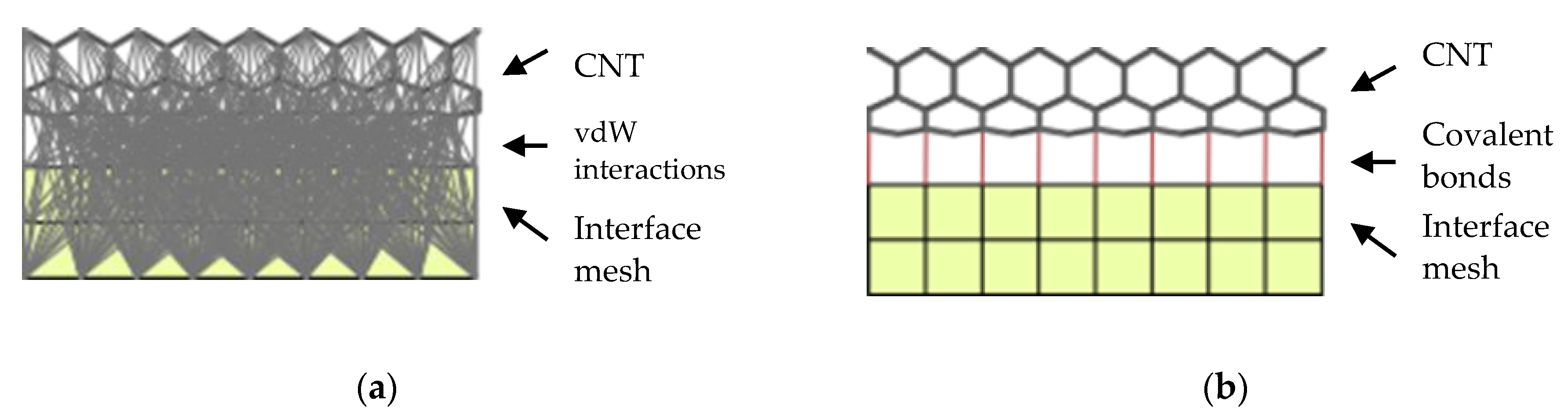
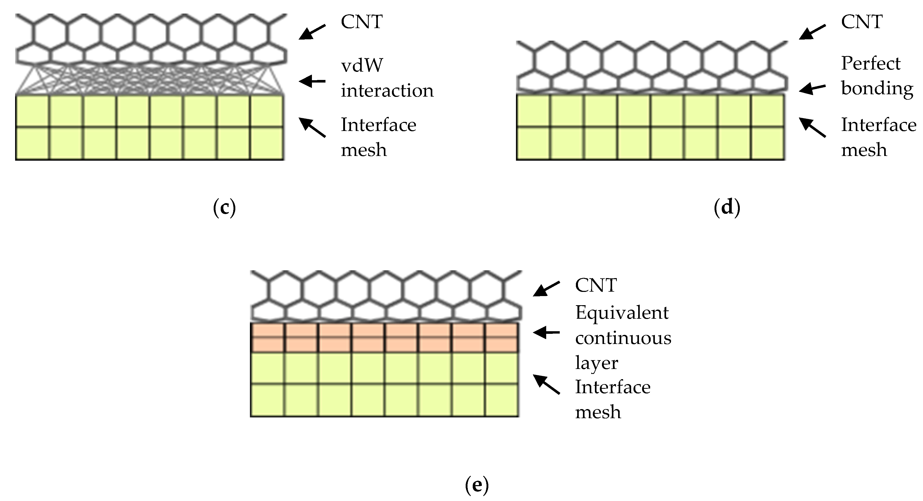
3. Modeling CNTs and CNT–Matrix Interface
4. Theory
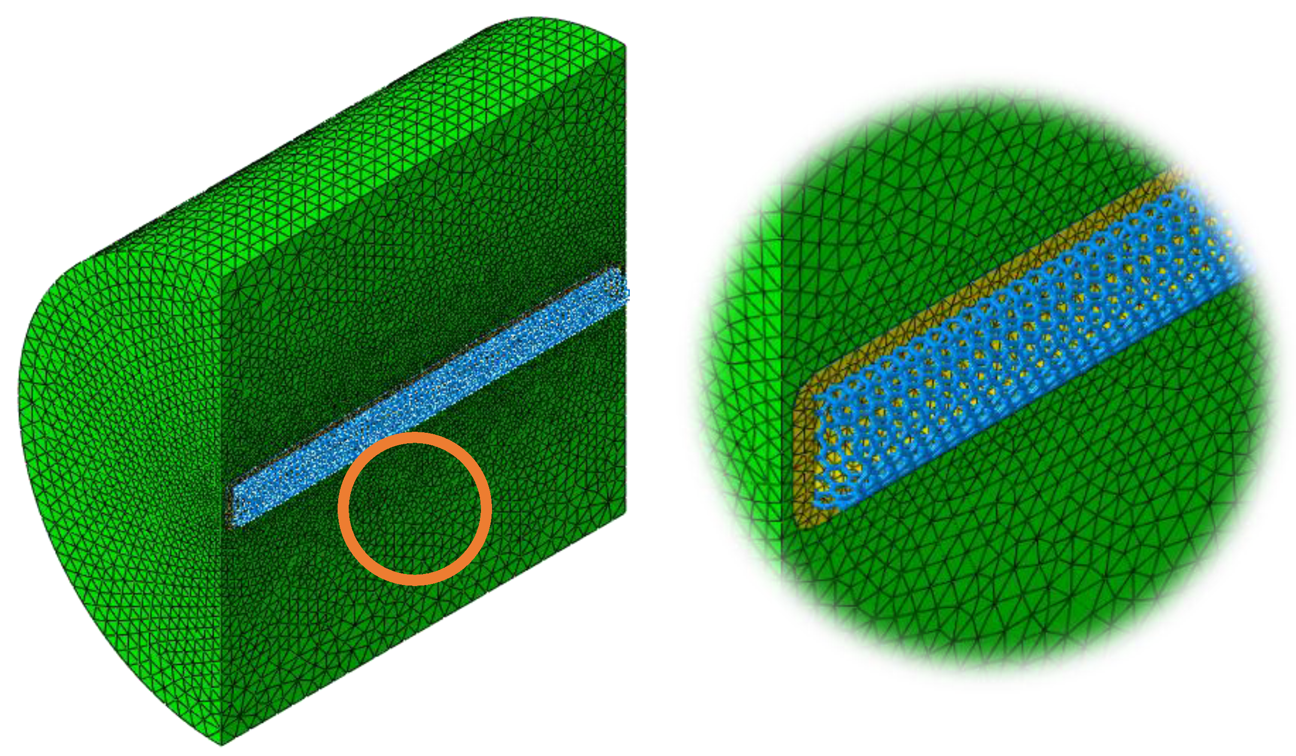
5. Representative Volume Element (RVE)
6. Homogenization
7. Results
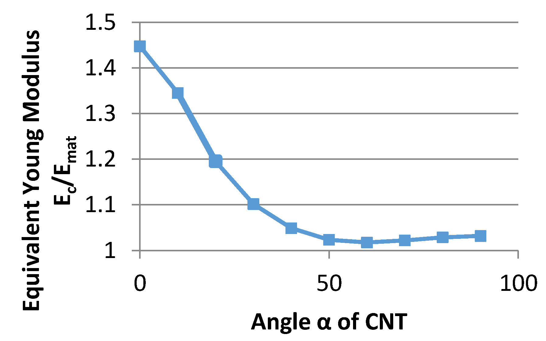
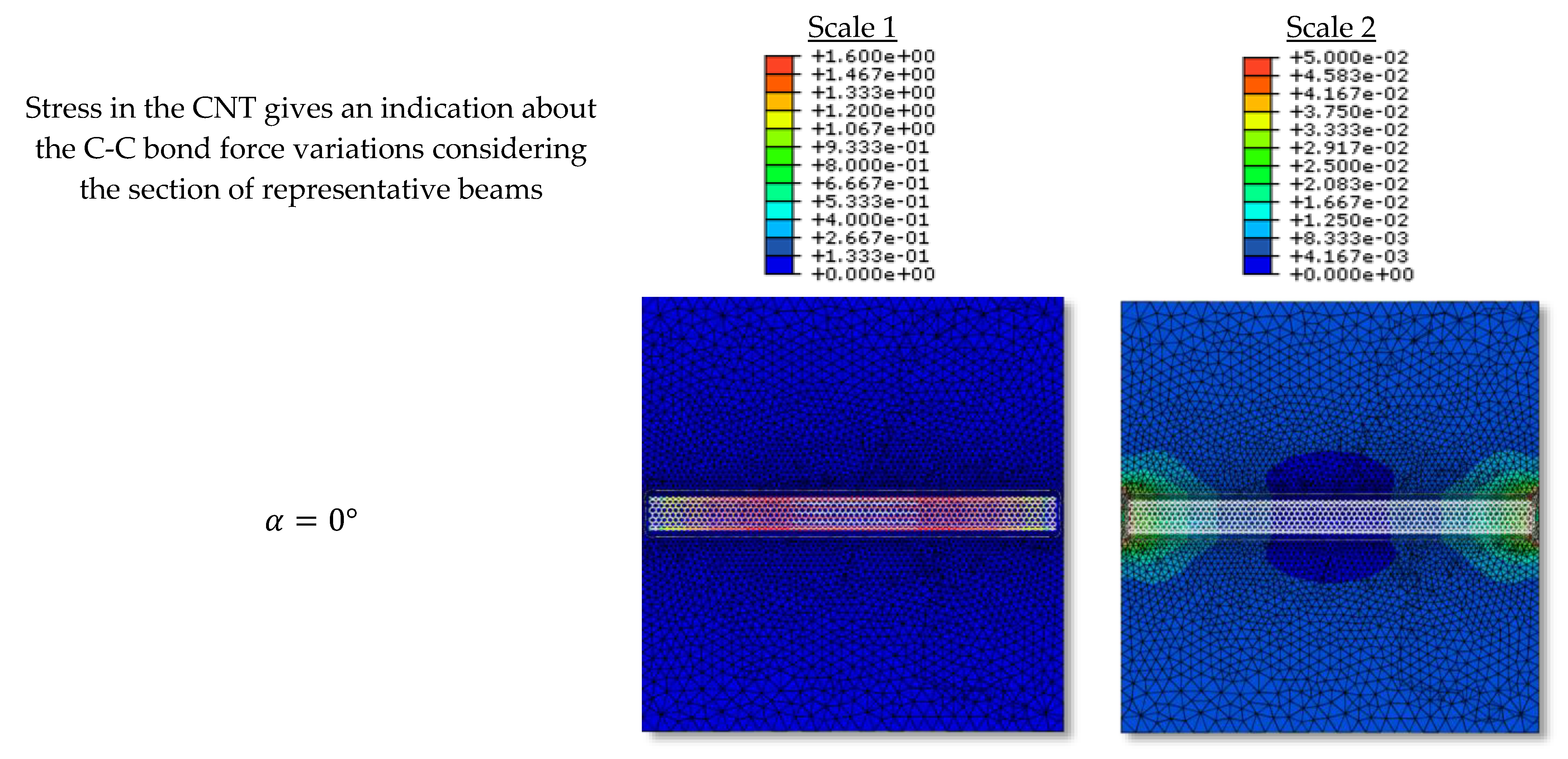
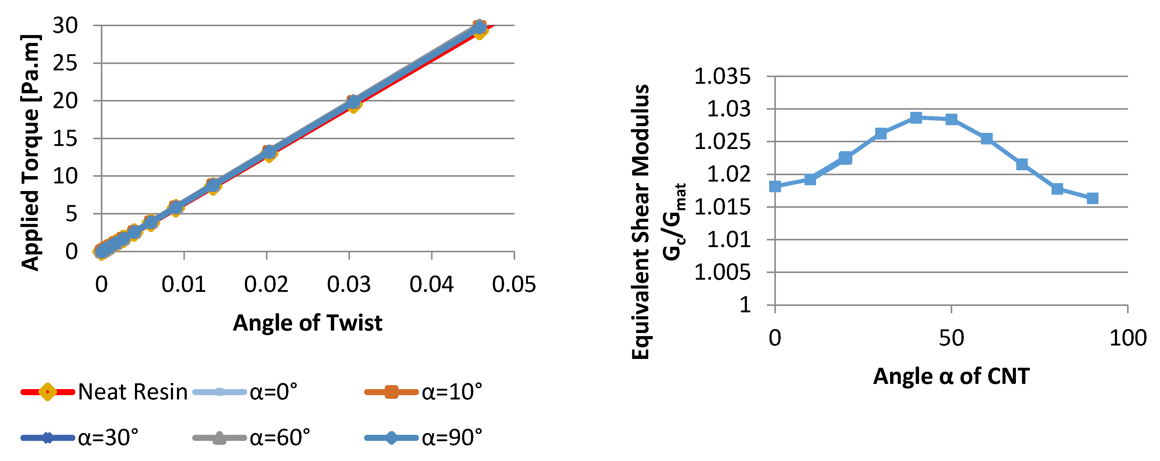
7.1. Influence of CNT Orientation
7.2. Tension and Compression
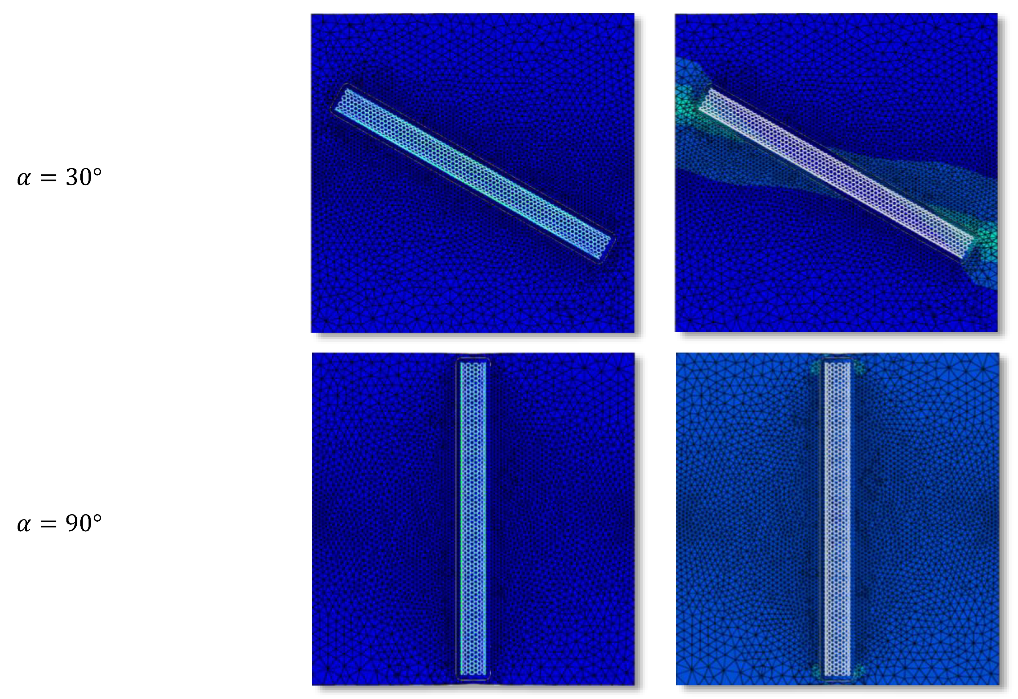
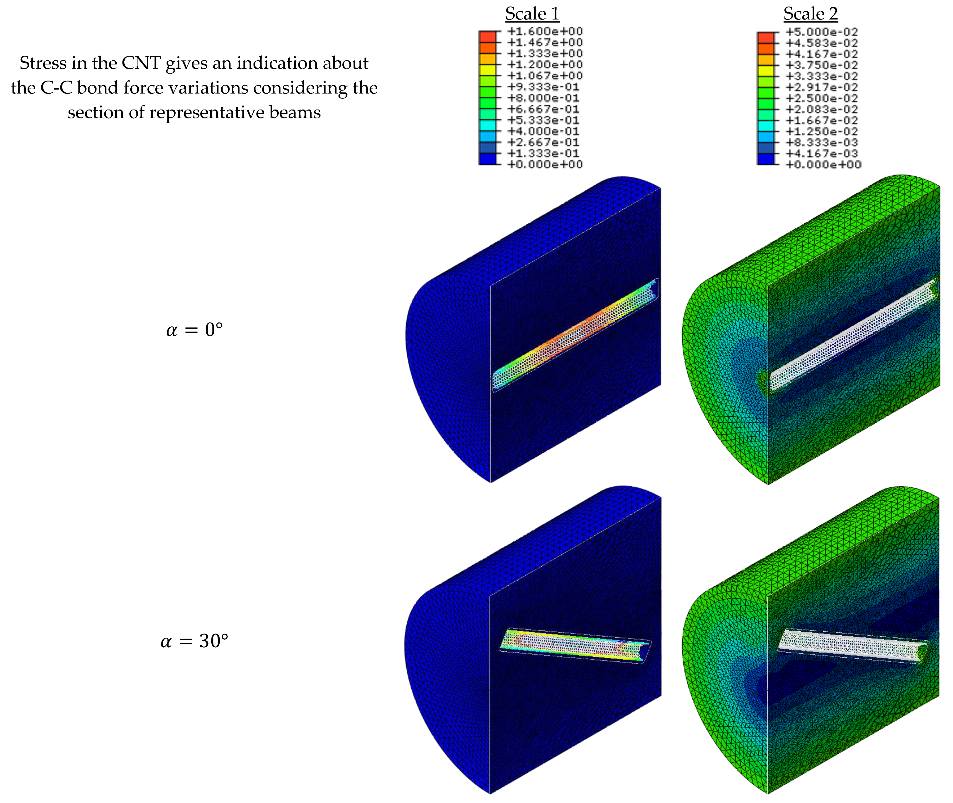
7.3. Torsion
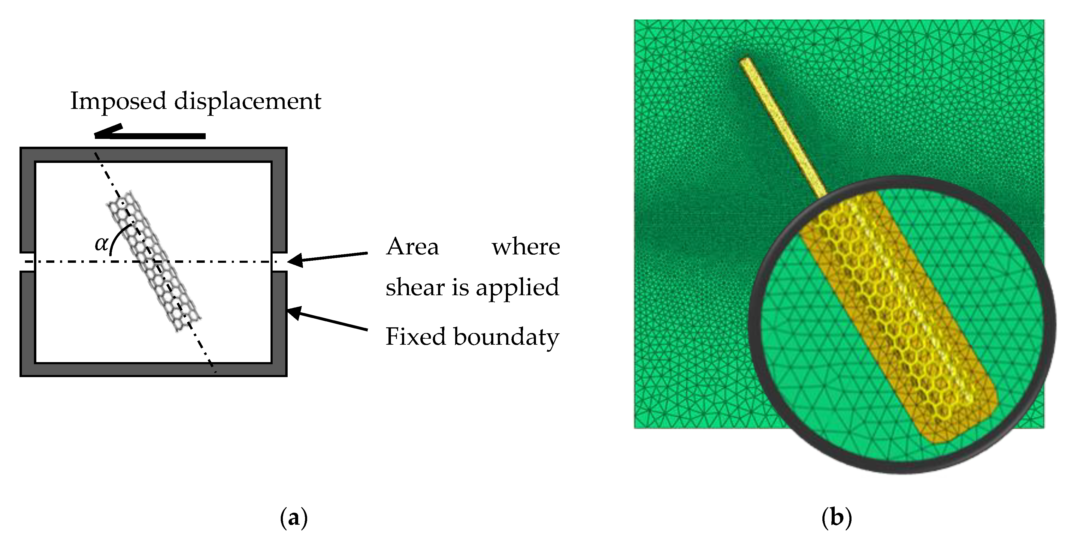
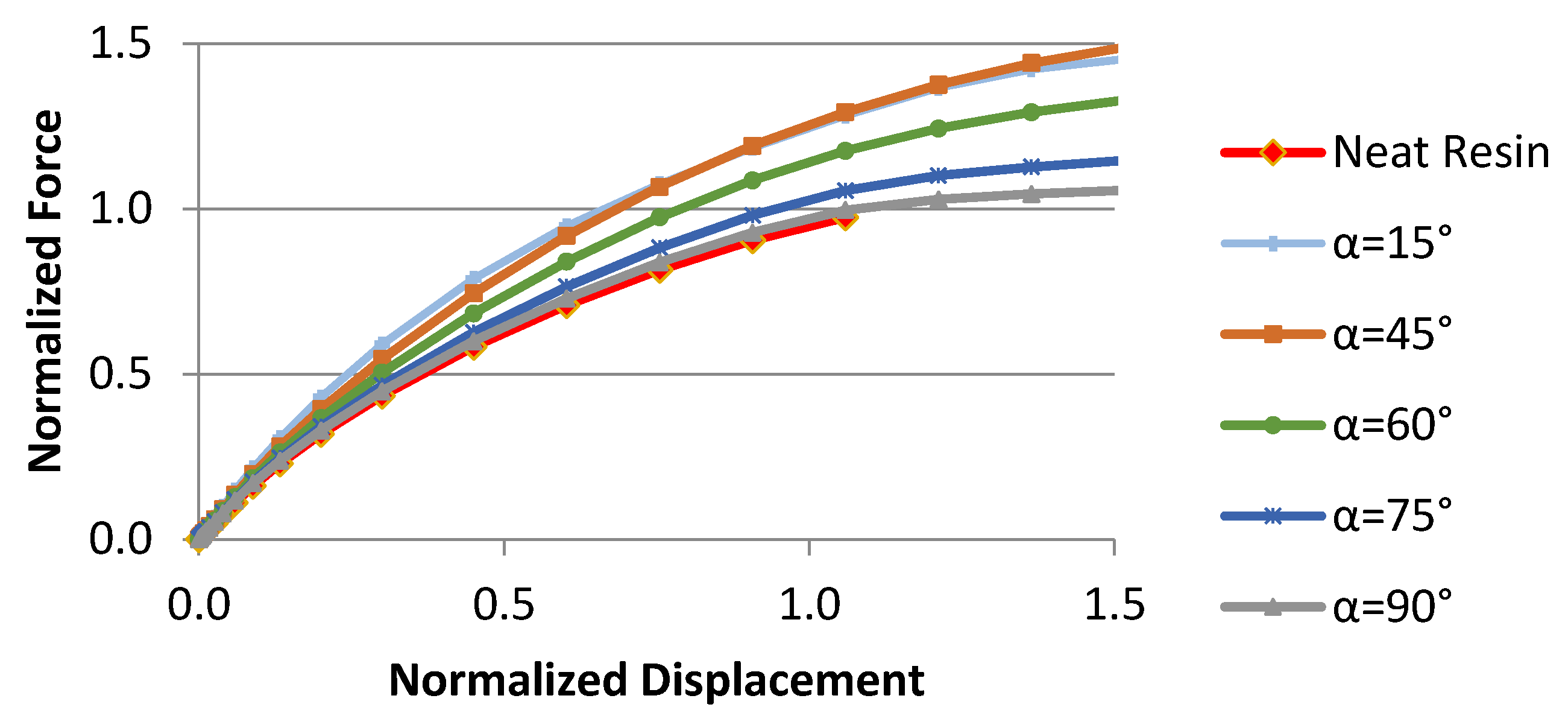
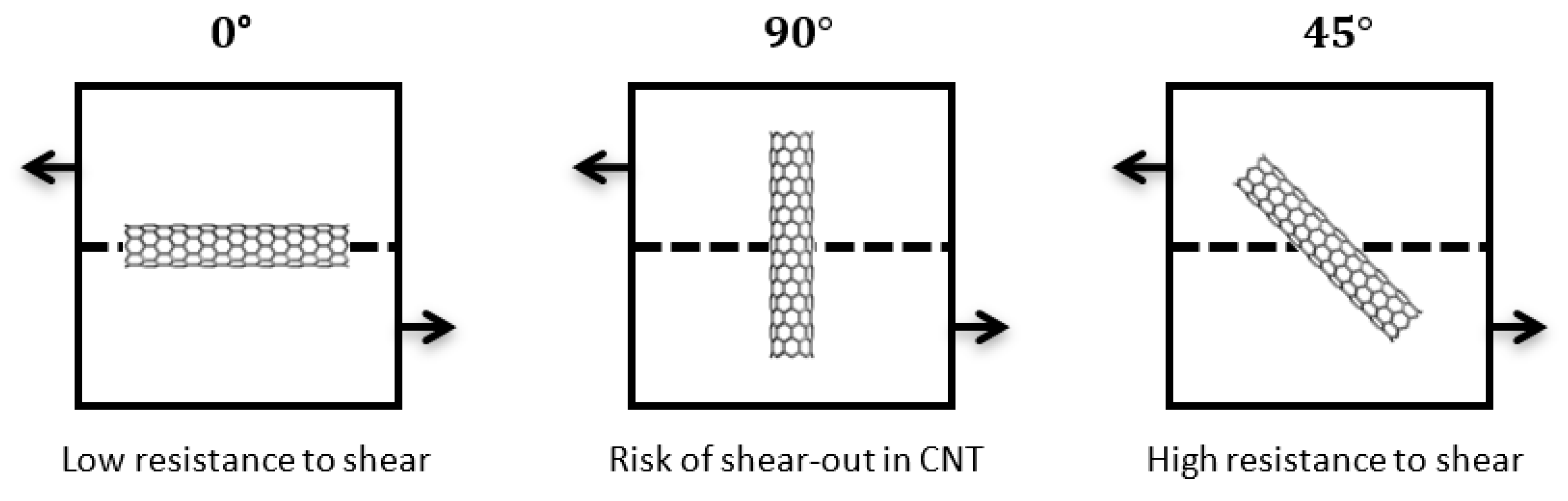
7.4. Shear Test
7.5. Macroscopic Stiffness Tensor of the Nanocell
8. Synthesis and Discussions
9. Observations about Engineering Use
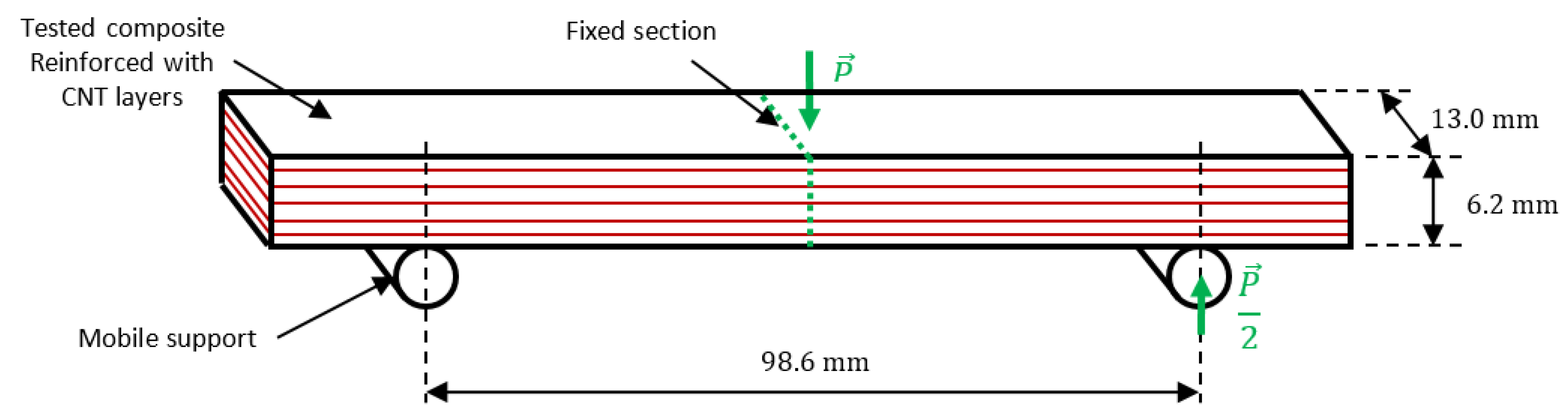
9.1. Unidirectional Specimen [0°]
9.2. 2-Dimensional Specimen [45°]
10. Prospective
11. Further Thinking
12. Conclusions
Author Contributions
Funding
Acknowledgments
Conflicts of Interest
References
- Drissi-Habti, M.; Raman, V.; Khadour, A.; Timorian, S. Fiber Optic Sensor Embedment Study for Multi-Parameter Strain Sensing. Sensors 2017, 17, 667. [Google Scholar] [CrossRef] [PubMed] [Green Version]
- Raman, V.; Drissi-Habti, M. Numerical simulation analysis as a tool to identify areas of weakness in a turbine wind-blade and solutions for their reinforcement. Compos. Part B 2016, 103, 23–39. [Google Scholar] [CrossRef] [Green Version]
- Raman, V.; Drissi-Habti, M. Numerical simulation of a resistant structural bonding in wind-turbine blade through the use of composite cord stitching. Compos. Part B Eng. 2019, 176, 107094. [Google Scholar] [CrossRef]
- El-Assami, Y.; Drissi-Habti, M. Stiffening offshore composite wind-blades bonding joints by carbon nanotubes reinforced resin–a new concept. J. Struct. Integr. Maint. 2020, 5, 87–103. [Google Scholar] [CrossRef]
- Thostenson, E.T.; Ren, Z.; Chou, T.-W. Advances in the science and technology of carbon nanotubes and their composites: A review. Compos. Sci. Technol. 2001, 61, 1899–1912. [Google Scholar] [CrossRef] [Green Version]
- Ruoff, R.S.; Qian, D.; Liu, W.K. Mechanical properties of carbon nanotubes: Theoretical predictions and experimental measurements. Comptes Rendus Phys. 2003, 4, 993–1008. [Google Scholar] [CrossRef]
- Meo, M.; Rossi, M. Prediction of Young’s modulus of single wall carbon nanotubes by molecular-mechanics based finite element modelling. Compos. Sci. Technol. 2006, 66, 1597–1605. [Google Scholar] [CrossRef]
- Tserpes, K.I.; Papanikos, P.; Tsirkas, S.A. A progressive fracture model for carbon nanotubes. Compos. Part B Eng. 2006, 37, 662–669. [Google Scholar] [CrossRef]
- Gou, J.; Lau, K. Modeling and Simulation of Carbon Nanotube/Polymer Composites. In Handbook of Theoretical and Computational Nanotechnology; American Scientific Publisher: New Orleans, LA, USA, 2005; Volume 1, pp. 1–33. [Google Scholar]
- Zeng, Q.H.; Yu, A.B.; Lu, G.Q. Multiscale modeling and simulation of polymer nanocomposites. Prog. Polym. Sci. 2008, 33, 191–269. [Google Scholar] [CrossRef]
- Montazeri, A.; Montazeri, N. Viscoelastic and mechanical properties of multi walled carbon nanotube/epoxy composites with different nanotube content. Mater. Des. 2011, 32, 2301–2307. [Google Scholar] [CrossRef]
- Mittal, G.; Dhand, V.; Rhee, K.Y.; Park, S.-J.; Lee, W.R. A review on carbon nanotubes and graphene as fillers in reinforced polymer nanocomposites. J. Ind. Eng. Chem. 2015, 21, 11–25. [Google Scholar] [CrossRef]
- Lahiri, D.; Bakshi, S.R.; Keshri, A.K.; Liu, Y.; Agarwal, A. Dual strengthening mechanisms induced by carbon nanotubes in roll bonded aluminum composites. Mater. Sci. Eng. A 2009, 523, 263–270. [Google Scholar] [CrossRef]
- Rousakis, T.C.; Kouravelou, K.B.; Karachalios, T.K. Effects of carbon nanotube enrichment of epoxy resins on hybrid FRP–FR confinement of concrete. Compos. Part B Eng. 2014, 57, 210–218. [Google Scholar] [CrossRef]
- Dong, S.; Zhou, J.; Hui, D.; Wang, Y.; Zhang, S. Size dependent strengthening mechanisms in carbon nanotube reinforced metal matrix composites. Compos. Part Appl. Sci. Manuf. 2015, 68, 356–364. [Google Scholar] [CrossRef]
- Sinnott, S.B.; Andrews, R. Carbon Nanotubes: Synthesis, Properties, and Applications. Crit. Rev. Solid State Mater. Sci. 2001, 26, 145–249. [Google Scholar] [CrossRef]
- Bellucci, S. Carbon nanotubes: Physics and applications. Phys. Status Solidi C 2005, 2, 34–47. [Google Scholar] [CrossRef]
- Vahedi, F.; Shahverdi, H.R.; Shokrieh, M.M.; Esmkhani, M. Effects of carbon nanotube content on the mechanical and electrical properties of epoxy-based composites. New Carbon Mater. 2014, 29, 419–442. [Google Scholar] [CrossRef]
- Sinnott, S.B.; Shenderova, O.A.; White, C.T.; Brenner, D.W. Mechanical properties of nanotubule fibers and composites determined from theoretical calculations and simulations. Carbon 1998, 36, 1–9. [Google Scholar] [CrossRef]
- Mao, Z.; Garg, A.; Sinnott, S.B. Molecular dynamics simulations of the filling and decorating of carbon nanotubules. Nanotechnology 1999, 10, 273. [Google Scholar] [CrossRef] [Green Version]
- Odegard, G.M.; Gates, T.S.; Wise, K.E.; Park, C.; Siochi, E.J. Constitutive modeling of nanotube–reinforced polymer composites. Compos. Sci. Technol. 2003, 63, 1671–1687. [Google Scholar] [CrossRef]
- Zuberi, M.J.S.; Esat, V. Investigating the mechanical properties of single walled carbon nanotube reinforced epoxy composite through finite element modelling. Compos. Part B Eng. 2015, 71, 1–9. [Google Scholar] [CrossRef]
- Liu, Y.H.B. The atomic-scale finite element method. Comput. Methods Appl. Mech. Eng. 2004, 193, 1849–1864. [Google Scholar] [CrossRef]
- Liu, H.J.B. Atomic-scale finite element method in multiscale computation with applications to carbon nanotubes. Phys. Rev. B 2005, 72. [Google Scholar] [CrossRef] [Green Version]
- Leung, A.Y.T.; Guo, X.; He, X.Q.; Jiang, H.; Huang, Y. Postbuckling of carbon nanotubes by atomic-scale finite element. J. Appl. Phys. 2006, 99, 124308. [Google Scholar] [CrossRef]
- Odegard, G.M.; Gates, T.S.; Nicholson, L.M.; Wise, K.E. Equivalent-continuum modeling of nano-structured materials. Compos. Sci. Technol. 2002, 62, 1869–1880. [Google Scholar] [CrossRef] [Green Version]
- Li, C.; Chou, T.-W. A structural mechanics approach for the analysis of carbon nanotubes. Int. J. Solids Struct. 2003, 40, 2487–2499. [Google Scholar] [CrossRef]
- Li, C.; Chou, T.-W. Multiscale Modeling of Carbon Nanotube Reinforced Polymer Composites. J. Nanosci. Nanotechnol. 2003, 3, 423–430. [Google Scholar] [CrossRef]
- Lu, X.; Hu, Z. Mechanical property evaluation of single-walled carbon nanotubes by finite element modeling. Compos. Part B Eng. 2012, 43, 1902–1913. [Google Scholar] [CrossRef]
- Li, C.; Chou, T.-W. Elastic moduli of multi-walled carbon nanotubes and the effect of van der Waals forces. Compos. Sci. Technol. 2003, 63, 1517–1524. [Google Scholar] [CrossRef]
- Li, C.; Chou, T.-W. Multiscale modeling of compressive behavior of carbon nanotube/polymer composites. Compos. Sci. Technol. 2006, 66, 2409–2414. [Google Scholar] [CrossRef]
- Gojny, F.H.; Wichmann, M.H.G.; Fiedler, B.; Schulte, K. Influence of different carbon nanotubes on the mechanical properties of epoxy matrix composites–A comparative study. Compos. Sci. Technol. 2005, 65, 2300–2313. [Google Scholar] [CrossRef]
- Fiedler, B.; Gojny, F.H.; Wichmann, M.H.G.; Nolte, M.C.M.; Schulte, K. Fundamental aspects of nano-reinforced composites. Compos. Sci. Technol. 2006, 66, 3115–3125. [Google Scholar] [CrossRef]
- Jeon, I.-Y.; Chang, D.W.; Kumar, N.A.; Baek, J.-B. Functionalization of Carbon Nanotubes. In Carbon Nanotubes-Polymer Nanocomposites; Intech: London, UK, 2011. [Google Scholar]
- Gojny, F.H.; Schulte, K. Functionalisation effect on the thermo-mechanical behaviour of multi-wall carbon nanotube/epoxy-composites. Compos. Sci. Technol. 2004, 64, 2303–2308. [Google Scholar] [CrossRef]
- Yang, Y.-B.; Shieh, M.-S. Solution method for nonlinear problems with multiple critical points. AIAA J. 1990, 28, 2110–2116. [Google Scholar] [CrossRef]
- Gupta, A.K.; Harsha, S.P. Analysis of mechanical properties of carbon nanotube reinforced polymer composites using multi-scale finite element modeling approach. Compos. Part B Eng. 2016, 95, 172–178. [Google Scholar] [CrossRef]
- Jiang, L.Y.; Huang, Y.; Jiang, H.; Ravichandran, G.; Gao, H.; Hwang, K.C.; Liu, B. A cohesive law for carbon nanotube/polymer interfaces based on the van der Waals force. J. Mech. Phys. Solids 2006, 54, 2436–2452. [Google Scholar] [CrossRef]
- He, X.Q.; Kitipornchai, S.; Wang, C.M.; Liew, K.M. Modeling of van der Waals force for infinitesimal deformation of multi-walled carbon nanotubes treated as cylindrical shells. Int. J. Solids Struct. 2005, 42, 6032–6047. [Google Scholar] [CrossRef] [Green Version]
- Esbati, A.; Irani, S. Mechanical properties and fracture analysis of functionalized carbon nanotube embedded by polymer matrix. Aerosp. Sci. Technol. 2016, 55, 120–130. [Google Scholar] [CrossRef]
- Liu, X.; Yang, Q.-S.; He, X.-Q.; Liew, K.-M. Cohesive laws for van der Waals interactions of super carbon nanotube/polymer composites. Mech. Res. Commun. 2016, 72, 33–40. [Google Scholar] [CrossRef]
- Namilae, S.; Chandra, N. Multiscale Model to Study the Effect of Interfaces in Carbon Nanotube-Based Composites. J. Eng. Mater. Technol. 2005, 127, 222–232. [Google Scholar] [CrossRef]
- Qian, D.; Dickey, E.C.; Andrews, R.; Rantell, T. Load transfer and deformation mechanisms in carbon nanotube-polystyrene composites. Appl. Phys. Lett. 2000, 76, 2868–2870. [Google Scholar] [CrossRef] [Green Version]
- Brenner, D.W.; Shenderova, O.A.; Harrison, J.A.; Stuart, S.J.; Ni, B.; Sinnott, S.B. A second-generation reactive empirical bond order (REBO) potential energy expression for hydrocarbons. J. Phys. Condens. Matter 2002, 14, 783. [Google Scholar] [CrossRef]
- Gao, X.-L.; Li, K. A shear-lag model for carbon nanotube-reinforced polymer composites. Int. J. Solids Struct. 2005, 42, 1649–1667. [Google Scholar] [CrossRef]
- Chang, T.; Gao, H. Size-dependent elastic properties of a single-walled carbon nanotube via a molecular mechanics model. J. Mech. Phys. Solids 2003, 51, 1059–1074. [Google Scholar] [CrossRef]
- Tserpes, K.I.; Papanikos, P. Finite element modeling of single-walled carbon nanotubes. Compos. Part B Eng. 2005, 36, 468–477. [Google Scholar] [CrossRef]
- Scarpa, F.; Adhikari, S. A mechanical equivalence for Poisson’s ratio and thickness of C–C bonds in single wall carbon nanotubes. J. Phys. Appl. Phys. 2008, 41, 085306. [Google Scholar] [CrossRef]
- Chen, Y.L.; Liu, B.; He, X.Q.; Huang, Y.; Hwang, K.C. Failure analysis and the optimal toughness design of carbon nanotube-reinforced composites. Compos. Sci. Technol. 2010, 70, 1360–1367. [Google Scholar] [CrossRef]
- Littell, J.D.; Ruggeri, C.R.; Goldberg, R.K.; Roberts, G.D.; Arnold, W.A.; Binienda, W.K. Measurement of Epoxy Resin Tension, Compression, and Shear Stress–Strain Curves over a Wide Range of Strain Rates Using Small Test Specimens. J. Aerosp. Eng. 2008, 21, 162–173. [Google Scholar] [CrossRef]
- Kumar, A.; Li, S.; Roy, S.; King, J.A.; Odegard, G.M. Fracture properties of nanographene reinforced EPON 862 thermoset polymer system. Compos. Sci. Technol. 2015, 114, 87–93. [Google Scholar] [CrossRef]
- Liu, Q. Hill’s lemma for the average-field theory of Cosserat continuum. Acta Mech. 2012, 224, 851–866. [Google Scholar] [CrossRef]
- Standard Test Method for Flexural Properties of Polymer Matrix Composite Materials; ASTM International: West Conshohocken, PA, USA, 2015.
- Soden, P.D.; Hinton, M.J.; Kaddour, A.S. Lamina properties, lay-up configurations and loading conditions for a range of fibre-reinforced composite laminates. Compos. Sci. Technol. 1998, 58, 1011–1022. [Google Scholar] [CrossRef]
- Hashin, Z. A Fatigue Failure Criterion for Fiber Reinforced Materials. J. Compos. Mater. 1973, 7. [Google Scholar] [CrossRef] [Green Version]
- Hashin, Z. Failure Criteria for Unidirectional Fiber Composites. J. Appl. Mech. 1980, 47, 329–334. [Google Scholar] [CrossRef]
- Bisheh, H.; Wu, N. Wave propagation in smart laminated composite cylindrical shells reinforced with carbon nanotubes in hygrothermal environments. Compos. Part B Eng. 2019, 162, 219–241. [Google Scholar] [CrossRef]
- Bisheh, H.; Wu, N.; Rabczuk, T. Free vibration analysis of smart laminated carbon nanotube-reinforced composite cylindrical shells with various boundary conditions in hygrothermal environments. Thin-Walled Struct. 2020, 149, 106500. [Google Scholar] [CrossRef]
- Drissi-Habti, M. A new chart method for assessing the performance of ceramic matrix composites and aiding numerical modelling. Annal. Chim. Sci. Matér. 2000, 25, 551–556. [Google Scholar] [CrossRef]


| Neat Matrix | 2.92 | 2.92 | 0.4 | 0.4 | 1.04 | 1.04 |
| CNT-reinforced matrix | 3.21 | 5.67 | 0.52 | 0.22 | 1.06 | 1.06 |
| Ratio | 1.10 | 1.94 | - | - | 1.01 | 1.01 |
| CFRP ply (tension) | 141 | 11 | 0.28 | 6.6 | 4.8 | 4.8 |
| CFRP ply (compression) | 128 | 11 | 0.28 | 6.6 | 4.8 | 4.8 |
| Reinforced resin in inter-ply | 6.7 | 0.4 | 1.6 | |||
| Compression strength-direction 1 | |||
| Compression strength-direction 2 | |||
| Tension strength-direction 1 | |||
| Tension strength-direction 2 | |||
| Shear strength | |||
| Transverse shear strength |
Publisher’s Note: MDPI stays neutral with regard to jurisdictional claims in published maps and institutional affiliations. |
© 2021 by the authors. Licensee MDPI, Basel, Switzerland. This article is an open access article distributed under the terms and conditions of the Creative Commons Attribution (CC BY) license (https://creativecommons.org/licenses/by/4.0/).
Share and Cite
Drissi-Habti, M.; El Assami, Y.; Raman, V. Multiscale Toughening of Composites with Carbon Nanotubes—Continuous Multiscale Reinforcement New Concept. J. Compos. Sci. 2021, 5, 135. https://0-doi-org.brum.beds.ac.uk/10.3390/jcs5050135
Drissi-Habti M, El Assami Y, Raman V. Multiscale Toughening of Composites with Carbon Nanotubes—Continuous Multiscale Reinforcement New Concept. Journal of Composites Science. 2021; 5(5):135. https://0-doi-org.brum.beds.ac.uk/10.3390/jcs5050135
Chicago/Turabian StyleDrissi-Habti, Monssef, Yassine El Assami, and Venkadesh Raman. 2021. "Multiscale Toughening of Composites with Carbon Nanotubes—Continuous Multiscale Reinforcement New Concept" Journal of Composites Science 5, no. 5: 135. https://0-doi-org.brum.beds.ac.uk/10.3390/jcs5050135