
Current Concepts for Cutting Metal-Based and Polymer-Based Composite Materials


1
Department of Manufacturing and Production Engineering, Rzeszow University of Technology, al. Powst. Warszawy 8, 35-959 Rzeszów, Poland
2
Department of Manufacturing Science and Engineering, Budapest University of Technology and Economics, Műegyetemrkp 3, H-1111 Budapest, Hungary
3
Kirkuk Technical Institute, Northern Technical University, Kirkuk 41001, Iraq
4
Department of Mechanical and Structural Engineering, University of Stavanger, N-4036 Stavanger, Norway
*
Author to whom correspondence should be addressed.
J. Compos. Sci. 2022, 6(5), 150; https://0-doi-org.brum.beds.ac.uk/10.3390/jcs6050150
Submission received: 3 May 2022
/
Revised: 15 May 2022
/
Accepted: 18 May 2022
/
Published: 19 May 2022
(This article belongs to the Special Issue Polymer Composites: Fabrication and Applications)
Abstract
:Due to the variety of properties of the composites produced, determining the choice of the appropriate cutting technique is demanding. Therefore, it is necessary to know the problems associated with cutting operations, i.e., mechanical cutting (blanking), plasma cutting plasma, water jet cutting, abrasive water jet cutting, laser cutting and electrical discharge machining (EDM). The criterion for choosing the right cutting technique for a specific application depends not only on the expected cutting speed and material thickness, but it is also related to the physico-mechanical properties of the material being processed. In other words, the large variety of composite properties necessitates an individual approach determining the possibility of cutting a composite material with a specific method. This paper presents the achievements gained over the last ten years in the field of non-conventional cutting of metal-based and polymer-based composite materials. The greatest attention is paid to the methods of electrical discharge machining and ultrasonic cutting. The methods of high-energy cutting and water jet cutting are also considered and discussed. Although it is well-known that plasma cutting is not widely used in cutting composites, the authors also took into account this type of cutting treatment. The volume of each chapter depends on the dissemination of a given metal-based and polymer-based composite material cutting technique. For each cutting technique, the paper presents the phenomena that have a direct impact on the quality of the resulting surface and on the formation of the most important defects encountered. Finally, the identified current knowledge gaps are discussed.
1. Introduction
Composites are structures made by combining two or more materials with different physico-mechanical properties. One of the components is the matrix that binds the composite together, and the other is the construction material responsible to give the composite an appropriate strength. The composite strength is the result of the properties of the component phases, the volume fraction of the phases, the method of distribution of the dispersed phase in the matrix and the geometric features of the dispersed phase [1,2]. An appropriate combination of the constituent materials and their orientation allows for obtaining a material with properties impossible to obtain with conventional methods of producing homogeneous materials [3]. Composites are widely used in a variety of applications in the automotive [4], aerospace [5,6] and medical industries [7] as well as sporting and consumer goods [8]. Approximately 57% of the original Boeing 787 Dreamliner structure consists of composites [9]. Subramanian and Cook [10] stated that 40% of the material loss takes place in drilling operations in the aviation industry, which justifies the need for research in the field of composite separation operations. Stone and Krishnamurthy [11] concluded that the rejection of parts made of composite laminates due to delamination damage in drilling operations during final assembly is as high as 60%.
Depending on the matrix type, composite materials are divided into metal-based and non-metal (polymer, ceramic) composites. Due to the type of reinforcing phase, there are composites reinforced with fibres or particles or in a dispersion manner. The main groups of composites include the metal matrix composite (MMC), ceramic matrix composite (CMC), aramid fibre-reinforced plastics (AFRP) or polymer-based composite materials (carbon fibre-reinforced plastics—CFRP, glass fibre-reinforced plastics—GFRP) [12]. Aramid fibre-reinforced polymer (AFRP) composites are used when the combination of low weight and high toughness is the main application criterion. CFRP composites show much higher stiffness than AFRPs.
Due to the heterogeneous and anisotropic properties of composites, the cutting of composite panels is different from the machining of metals. Moreover, despite the combination of the fibres and the matrix into a single structure, the constituent materials retain their original mechanical and thermal properties, which usually differ substantially [13]. For this reason, multilayer structures should be classified as difficult-to-machine materials. The popularisation of composite materials requires effective methods of their processing. The character of the production of composites allows the formation of structures with a shape corresponding to the finished product. However, operations such as edge trimming, cutting to size and cutting holes are in many cases necessary [14,15]. Machining processes are widely used but require special attention in terms of the choice of tool material and machining parameters. Among the disadvantages of the mechanical cutting of fibrous composites, i.e., delamination, drawing of the fibres and inadequate quality (surface roughness) of the cut surface, the delamination is critical from the point of view of the mechanical strength of the composite [16,17].
In addition to conventional machining using cutting tools, the methods of high-energy cutting (laser cutting) and water jet techniques are widely used. These methods are also used for cutting and making holes in composite plates. Other methods that have attained a certain level of success for the drilling of metal-based and polymer-based composite materials include drilling with pilot hole [18], high-speed drilling [19], orbital drilling [20], ultrasonic drilling [21], use of cutting fluid during drilling [22], rotary ultrasonic machining [23], vibration-assisted twist drilling [24], rotary ultrasonic elliptical machining [25], grinding drilling [26], use of a back-up plate during drilling [27], etc.
Reinforcing fibres and other matrix components, such as glass, aluminium oxide and silicon carbide, are very hard and highly abrasion-resistant. Ensuring the optimal processing of composites using machining requires the use of special tool materials and tools with the appropriate blade geometry [28]. The non-contact cutting techniques, i.e., with a laser or a high-pressure water jet, do not have these limitations. Moreover, these methods do not require the use of lubricants that (i) can chemically react with the components of the composite and (ii) must be removed at subsequent stages of the production process [29].
When cutting composites, it is necessary to take into account the disturbance of the filler continuity, which worsens the material properties [1]. Another problem is ensuring the appropriate processing temperature by controlling the temperature below the resin curing temperature. The mechanical processing of composites is associated with the phenomenon of loss of cohesion between the component layers or loss of cohesion between individual fibres. Laser cutting provides a solution to some of these problems.
The unlimited possibility of producing composites with a wide range of properties and different workability for processing means that the selection of the appropriate cutting technique should be made individually. The use of an inadequate cutting technique may lead to delamination of the composite structure in the area of the cut edge, leading to a reduction in the structure’s resistance to long-term fatigue loads. In aerospace composite applications, such as wing skins, tail and frames, the quality of the cut surface plays a key role in ensuring the aircraft’s durability and structural reliability. This article reviews the latest advances in the non-conventional cutting methods of metal-based and polymer-based composite materials that have emerged over the last ten years. This paper is focused on high energy cutting methods and the abrasive jet cutting technique. The methods of electrical discharge machining and ultrasonic cutting, which are used to a limited extent, are also taken into account. This systematic review has been conducted according to the systematic reviews and meta-analyses (PRISMA) guidelines [30].
2. Laser Cutting
The laser cutting technique is a method of the thermal separation of material, which occurs through the interaction of a beam of continuous or pulsed laser radiation, which causes local melting or the melting and evaporation of the material being cut [31,32]. The melt is blown out of the cutting zone by a stream of reactive or inert gas. The accompanying gas pressure depends on the thickness and type of material to be cut and can reach 8 bar [33]. Depending on the grade of cut material, the accompanying gases in the cutting process are nitrogen, argon, air or oxygen [33,34]. Among the many available sources of the laser beam, the most frequently used are lasers whose active medium is a neodymium-doped yttrium aluminium garnet laser, denoted Nd:YAG [35], with a power of up to approximately 20 kW, in which the yttrium aluminium grenade rod is pumped with diode lasers. In neodymium glass (Nd:Glass) lasers the active medium are optical glass rods doped with Nd2O3 with a power of up to about 4 kW. High power diode lasers (HDPLs) use a power not exceeding 4 kW, where the laser source is light emitting diodes, mainly with GaAs doped with Al, In or P. Increasingly used, mainly in medicine and precision mechanics, are excimer lasers in which the active medium is a mixture of CO2, CO, N2, O2, He, Xe compounds and compounds F and Cl, and emit a beam in the range of ultraviolet radiation. Typical examples of excimer lasers are XeF excimer lasers (wavelength of 351 nm), XeCl excimer lasers (wavelength of 308 nm), KrF excimer lasers (wavelength of 248 nm) and ArF excimer lasers (wavelength of 193 nm) [36].
Lasers, as a non-contact and, therefore, frictionless cutting technique, eliminate tool wear, vibration and cutting forces [34,37]. Laser cutting can be easily automated and performed at high speed. In the early decades of using lasers to cut CFRPs, serious obstacles in the industrial use of laser cutting were the excessive heat-affected zone (HAZ), carbonisation, chemical degradation of the resin and delamination due to different thermal expansion of the composite components. The HAZ is mainly related to the input parameters of the laser cutting process [38,39]. Advances in the form of increased laser power, high beam quality and well-modulated ultra-short pulse systems make it possible to shorten the time the laser beam interacts with the composite. Laser processing systems can cooperate with six-axis industrial robots implementing a cutting trajectory in three-dimensional space. In other design solutions, a swivel head is used.
While cutting metal-based fibre metal laminates (FMLs) is technically possible at speeds corresponding to the cutting of a homogeneous metal, which is due to a very large difference in the thermophysical properties of the laminate components, qualitative cutting of these materials is extremely difficult. Thus, overburning of the polymer-, glass fibre layer is usually expected.
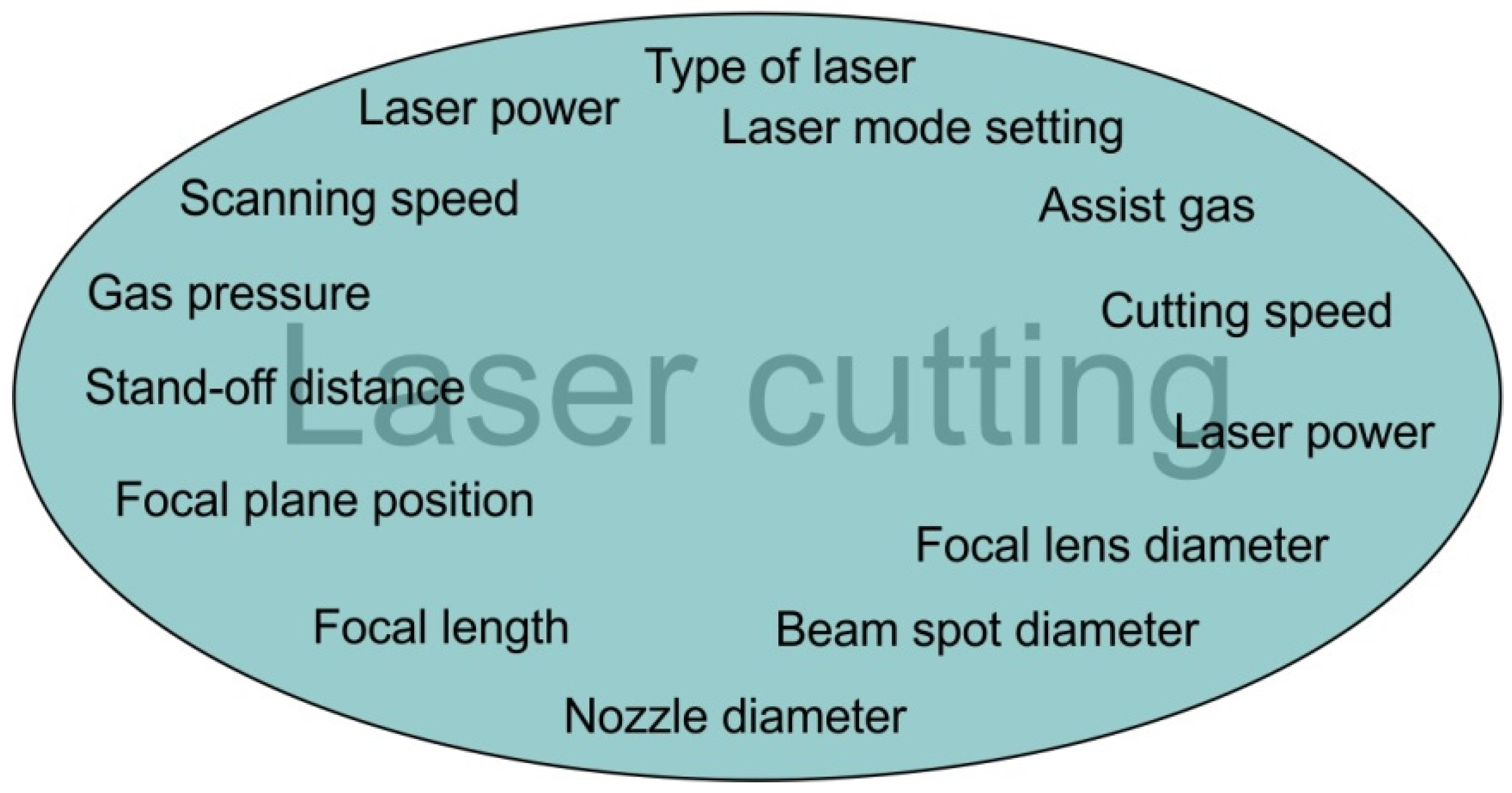
The anisotropic properties of fibre-reinforced composite materials opens up special application possibilities for asymmetrically loaded components. The selective reinforcement of the structure in the preferred directions increases the stiffness of the structure and enables the production of structures with a low coefficient of thermal expansion. A unique feature of many FMLs and fibre-reinforced composites (FRCs) is their high tendency to dampen vibrations. This leads to a better absorption of the vibration energy in the material and reduces the transmission of noise and vibrations to adjacent structural elements. Among the many parameters (Figure 1) affecting the laser cut edge, the most important of them are laser power, cutting speed, gas type, pulse duration, pulse energy, pulse repetition rate, gas pressure and the material thickness.
During the laser cutting of CFRPs, the phenomenon of sublimation occurs, during which the cut material is spontaneously evaporated in the cutting kerf as a result of the action of a high-intensity laser beam and blown out from the cutting kerf due to the high pressure of cutting gas. In the presence of sufficient power density during the cutting of polymer-based composites 103 W/cm2, the temperature of the cut material exceeds its melting point. The vapors and gases generated, especially during the processing of polymer composites, may be toxic and hazardous to the operator’s health, therefore, appropriate and safe working conditions must be ensured. The cut edges of the composite are smooth and there is no fraying of the fibres typical of machining.
Laser beam machining (LBM) technology is one of the most important methods employed to cut composites because it is a non-contact cutting method and it does not require much force to fix the workpiece [40,41]. LBM technology is successfully used to cut sugar palm fibre-reinforced unsaturated polyester (SPF-UPE) composites cut with a CO2 laser [42].
Compared to the high-pressure water jet cutting process, laser cutting allows for narrower cut kerfs at higher cutting speeds, while also ensuring a more accurate cut close to the edge of the composite. In relation to fibre-reinforced polymers (FRPs), laser treatment causes typical damage such as the delamination of layers, conical surface of the cutting kerf, formation of craters and occurrence of a heat-affected zone. The occurrence of these defects lowering the static and fatigue strength of the composite structure depends on the parameters of the laser beam, the assisting gas and the properties of the cut material. Thermosetting resins existed in FRPs are removed from the cut zone by chemical degradation that requires higher temperature and energy compared to thermoplastics. Reinforcing fibres generally require higher temperatures and energy to evaporate compared to the resin.
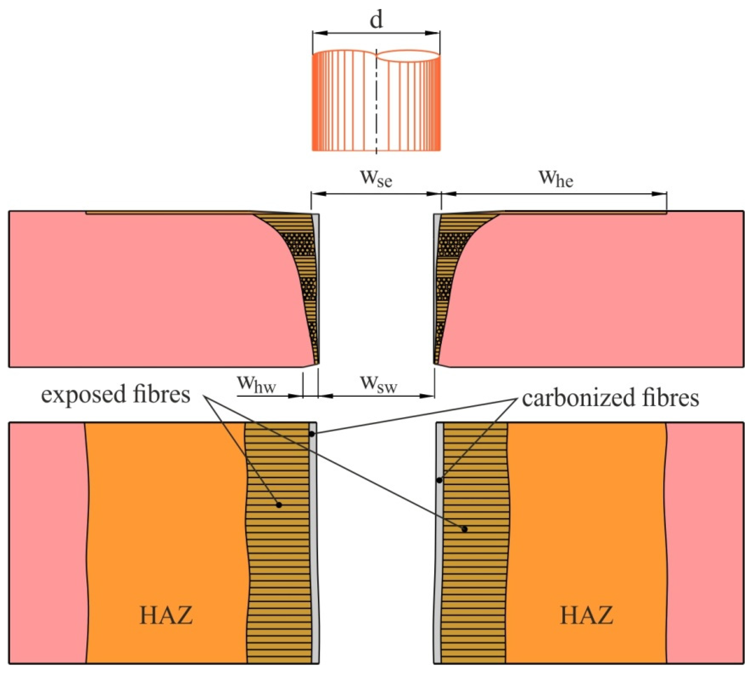
Quantitatively, the state of the cut edge can be characterised on the basis of the values of the following parameters (Figure 2) [43]:
- Whe—the total width of the HAZ on the side of the beam entering the material;
- Whw—total width of the HAZ on the side of the beam exit from the material;
- Wse—the width of the kerf on the side of the beam entering the material;
- Wsw—the width of the kerf on the side of the beam exit from the material.
Figure 2.
A typical composite surface after laser cutting (adapted with permission from Ref. [43]. 1988, copyright Taylor & Francis).
Figure 2.
A typical composite surface after laser cutting (adapted with permission from Ref. [43]. 1988, copyright Taylor & Francis).

Due to the large number of types of composites and possible defects related to the interaction of the laser beam with the composite material, as well as the influence of the configuration of the materials on the quality of the cut, universal guidelines for the assessment of cut edges have not been developed. The studies by Caprino and Tagliafferi [44] are a step forward; they proposed three quantitative-qualitative classes of edge quality:
- class A (good quality)—wsz ≤ d (d—diameter d of the laser beam); length of exposed fibres Lw ≤ 50 μm, no carbonisation of the cut surface;
- class B (acceptable quality)—all of the laser beam diameter d, wsz~d, 50 μm ≤ Lw ≤ 150 μm, visible carbonisation of the edges;
- class C (unsatisfactory quality)—wsz > d, Lw > 150 μm, significant carbonisation of the edges.
Glass and graphite fibres show a much longer evaporation time than the matrix. The phenomenon of evaporation in combination with the high thermal conductivity of carbon fibres leads to a deterioration of the cut quality of composites containing glass or carbon fibres compared to composites containing aramid fibres [45]. AFRP composites are laser cut to a thickness of 9.5 mm. The processing speed is 2–2.5 times faster than the cutting speed obtained in machining. FRPs generally show high light absorption in the infrared region, so deep penetration of the laser beam occurs at a much lower power intensity value (100–1000 W/cm2) than for metals (106 W/cm2).
Lasers emit radiation with a non-uniform power density distribution, which can be optimised for a given technological process by appropriate optical systems. In the cutting process, the non-uniform Gaussian distribution is used with the highest value of the radiation power density in the axis of the laser beam [46]. The technological parameters that determine the quality of cutting composites, in particular FRPs, are the laser power related to the power density distribution and the cutting speed. Increasing the cutting speed and reducing the laser power leads to a reduction in the size of the heat-affected zone and a reduction in the width of the cutting kerf. At the same time, the faster cutting speed reduces the excessive heating of the material and its carbonisation. The width of the heat-affected zone near the cutting kerf ranges from 100 μm to 1000 μm, mainly depending on the intensity of the laser beam, the power density distribution and the thickness of the composite. The thermal load on the composite material during laser cutting can be reduced by using multi-pass strategies [47,48].
It is assumed that the parameter responsible for the quality of the cut is the ratio of the laser power to the cutting speed. The minimum value of this factor when cutting FRPs is particularly dependent on the thickness of the composite and the type of fibres. CFRP composites require a high value, and AFRP composites require a low value of the ratio of laser power to cutting speed, with the same cutting thickness and the same volume fraction of reinforcing fibres. For cutting CFRPs, pulsed lasers are preferred, which can generate short bursts of high-power energy. The effect of a beam with such characteristics reduces the time of temperature impact on the cut material and significantly improves the cutting quality of FRPs. The size of the HAZ is proportional to the pulse energy. Higher beam intensity of Nd:YAG lasers, shorter interaction time and better focusing contribute to a lower thermal load on the cut material compared to CO2 lasers. The HAZ can be limited to a few micrometers when cutting with pulsed lasers with pulses in the picosecond or femtosecond range. A limitation in the economic industrial use of lasers with such pulse frequency is their low power. Excimer lasers emitting ultraviolet (UV) radiation significantly reduce thermal damage to the edges of the composites; however, the cutting speeds obtained are an order of magnitude lower than in the case of an infrared beam [49].
The fibre orientation and the lay-up sequence influence the temperature distribution in FRP composites and, thus, the quality of laser cutting. When cutting in the direction perpendicular to the fibres, the heat from the laser beam is dissipated by the fibres outside the cutting zone and, therefore, the efficiency of the process is lower compared to cutting in the direction parallel to the fibres, where the heat of the laser beam is used to preheat the material [50]. The different thermal expansion coefficients of carbon fibres in the radial and longitudinal directions leads to the significant difference between the thermophysical properties of the fibres and the polymer matrix of CFRPs. The high thermal conductivity of carbon fibres is the main source of problems related to damage of the cut edge during laser cutting.
The laser beam can also be used, in addition to cutting, to prepare the surface of CFRP composites for gluing by removing the top layer of the material, which improves the adhesion of the adhesive to the surfaces to be joined. Composite materials with a thickness from 1–8 mm are most often cut with a laser. In the case of thicker materials, a more advantageous solution is to use abrasive water jet cutting [51]. Laser cutting is feasible for cutting stainless steel and C/Epoxy composites, but the cutting surface has very low quality [52]. However, the development of gases from the burning epoxy matrix led to the spitting of melted metal around the location of the cut.
Multiple-pass cutting using a high beam quality continuous wave mode fibre Nd:YAG laser is effective to minimise delamination of CFRPs at low power level and high scanning speeds [53]. A novel technique using mixing of reactive and inert gases to minimise the matrix recession was introduced by Negarestani [53]. Nanosecond pulsed Nd:YAG laser cutting allowed to reduce the thermal damage as compared to the fibre laser while retaining high processing rate. Moreover, nanosecond pulsed beam multiple-pass cutting reduced the matrix recession.
Limited studies have been found with the aim of improving the HAZ of natural fibre-reinforced composites. Masoud et al. [42] examined the HAZ of sugar palm fibre-reinforced unsaturated polyester (SPF-UPE) composites cut with a CO2 laser. Results of the Taguchi statistical method and analysis of variance show that the minimum levels of laser power and the highest levels of traverse speed and gas pressure gave the optimum response to the HAZ. Tewari et al. [54] evaluated the HAZ response of kenaf-reinforced high-density polyethylene composite that was cut with a low-power CO2 laser. It was found that that traverse speed and laser power are the influential parameters on the HAZ in the laser-drilled kenaf-reinforced composite. Tamrin et al. [39] evaluated the HAZ during low-power CO2 laser cutting of cotton fibre laminate-reinforced phenolic resin. As a response to input parameters, laser power, traverse speed, stand-off distance and the number of beam passes were considered as input parameters in analysis of variance along with Taguchi experimental design. HAZ is most influenced by the traverse speed and laser power. The HAZ depth is inversely proportional to traverse speed.
Lau et al. [55] performed experiments on the efficiency of the Nd:YAG laser and the excimer laser for CFRP cutting. Their results indicate that intermittent cuts produce a poorer surface finish, and cutting speed is critical. Sobru et al. [56] found that assisted gas pressure, laser power, pulse ratio and focal plane position were the most influenced parameters for affecting the depth of cut by adapting the spiral trepanning drilling strategy for the cutting of multi-directional multi-layer CFRP. Hirsh et al. [57] applied the single mode fibre laser to cut GFRP, CFRP and continuous fibre-reinforced thermoplastic composites. The formation of the HAZ was found to be dependent on the laminate type and break time. During cutting perpendicular to the fibre axis and with a higher break time, the HAZ is reduced. The main cutting mechanisms for the CFRPs are vaporisation-induced ablation, thermochemical decomposition and melting, while the matrix polymer is removed during the laser cutting of GFRPs.
3. Water Jet and Abrasive Water Jet Cutting
Because of its remarkable advantages for machining metal or composite-based materials, water jet (WJ) and abrasive water jet (AWJ) technologies have been attractive manufacturing techniques for the space, aircraft, boating and automotive industries. Water jet machining, also called water jet cutting, is an unconventional machining process that performs based on the idea of water erosion to remove materials from the workpiece’s surface or to cut it into two sections by a high-velocity water jet. Soft materials, such as plastic and rubber, can be cut with water jet machining, and hard metals can be cut or milled by an AWJ. Using abrasive material in the water during the machining operation to cut materials is referred to as abrasive waterjet machining. The purpose of the abrasive particles is to enhance the cutting ability of the water jet. Garnet, aluminium oxide and sand are the most widely utilised abrasive particles in abrasive water jet machining; however, glass beads are also employed. Pure water jet machining is used to cut softer materials, but abrasive water jet machining is used to cut harder materials by mixing abrasive particles with the water. During cutting with a WJ or AWJ, the stream of the working medium is directed to the surface of the processed material through a nozzle with a diameter from 0.1–0.4 mm, causing erosive detachment of the processed material particles. The advantage of water jet cutting is the elimination of high temperature impact on the edge of the composite [58].
Water jet cutting is widely used for processing composite materials, plastics, elastomeric materials, wood, fabrics and mats [59,60]. This cutting technique consumes less energy compared to other cutting techniques (laser, plasma), and during the cutting process itself, no harmful substances are emitted. WJ technology has been developed with an AWJ, abrasive suspension jet (ASJ) and abrasive suspension jet micro-cutting (μASJ) techniques.
Current efforts of manufacturers of WJ cutting machines are aimed at further reducing the diameter of the hole in the nozzle and the diameter of the mixing nozzle with an exit hole less than 200 µm, as well as increasing the service life of the heads. Currently, properly operated mixing nozzles, depending on the quality of workmanship, can work for up to 140 h. The smallest parts that can be processed with μAWJ are approximately from 200–300 μm. The current intention of the manufacturers of machining machines is to process parts with dimensions from 50–100 μm. To ensure high shape and dimensional accuracy of the workpiece, the cutting jet leaving the nozzle is at a speed of nearly 3 times the speed of sound in air [61].
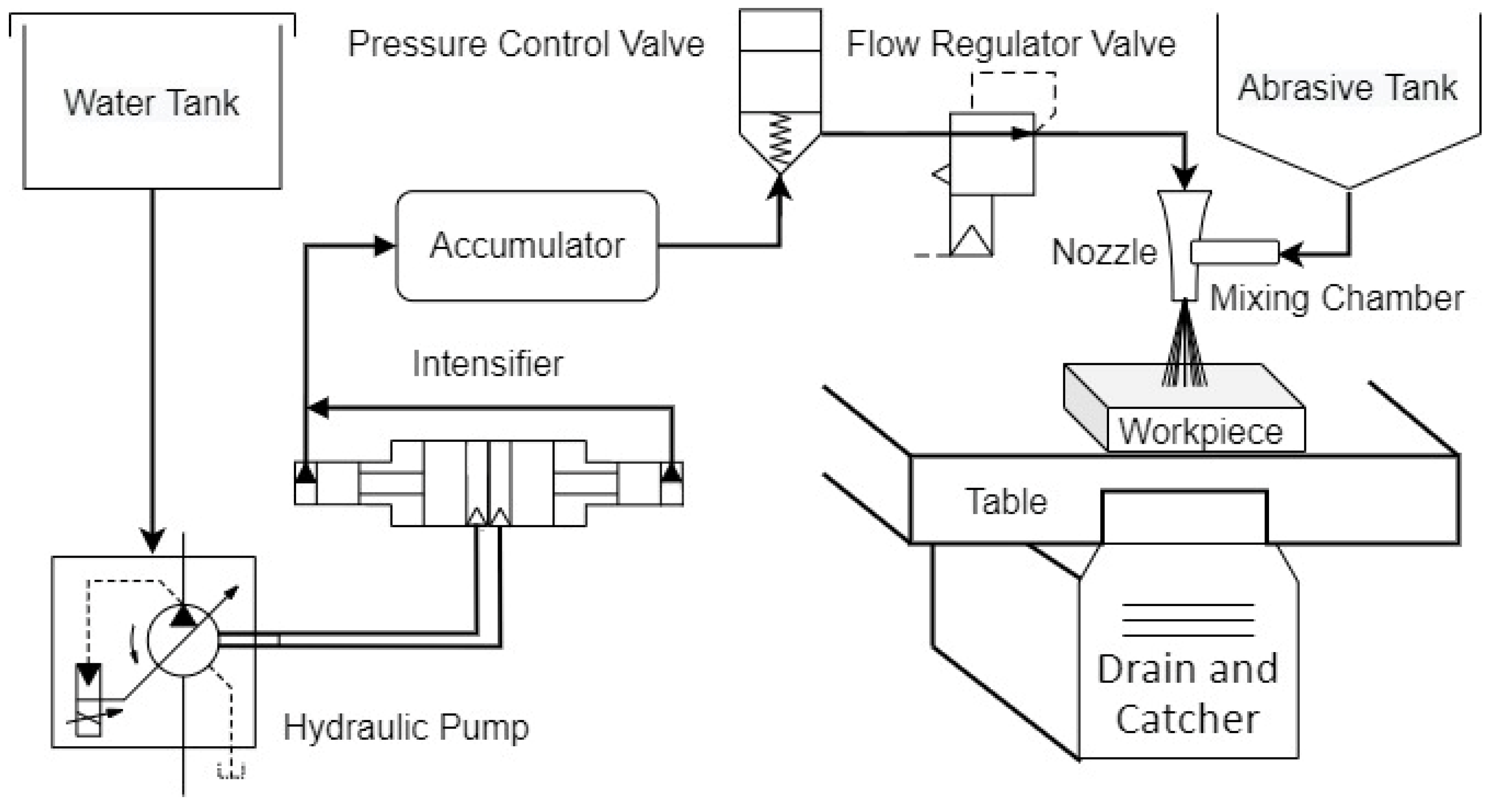
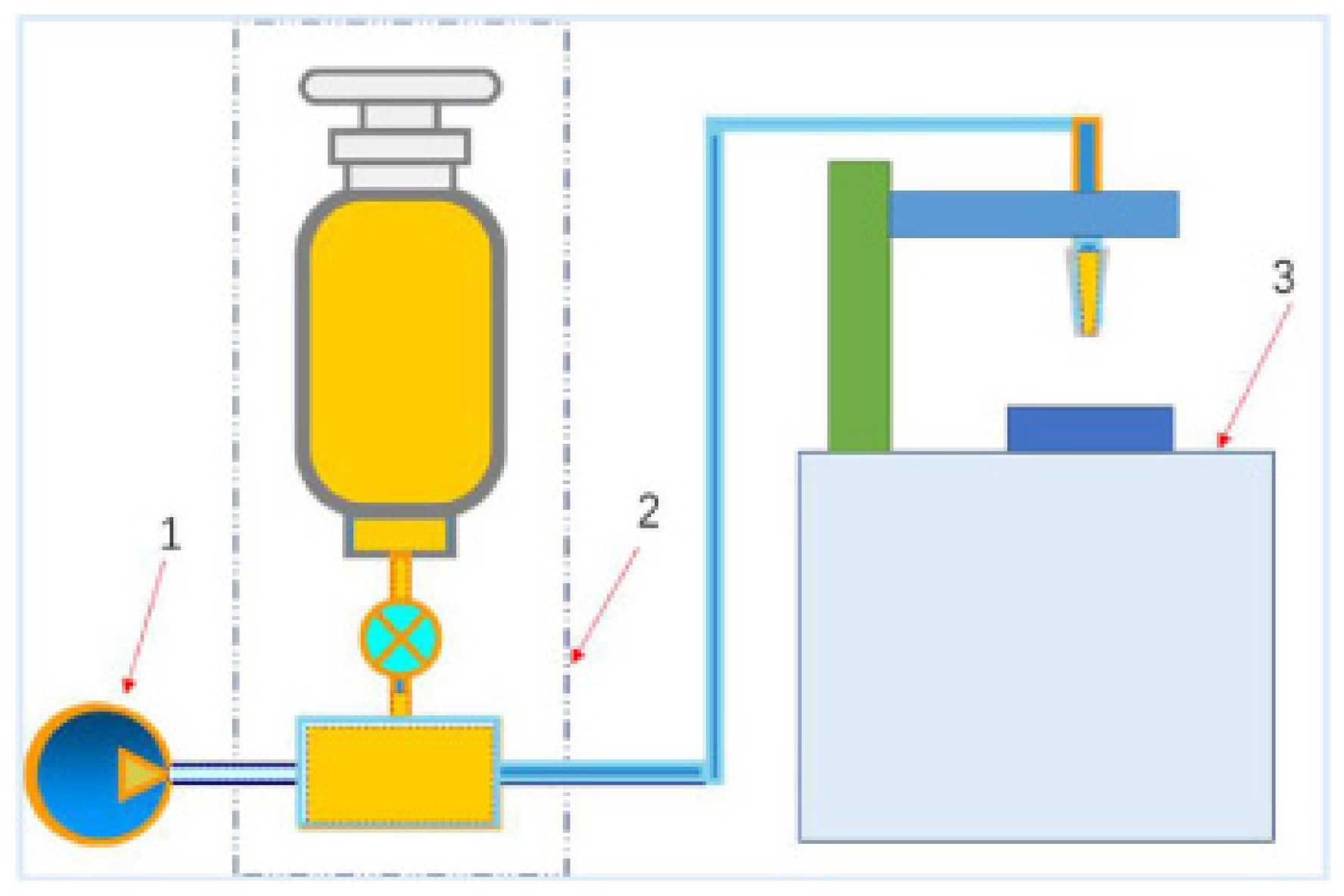
Many essential parts make up the water jet machining construction, as shown in Figure 3. A water tank serves to store the water needed for the machining process. During the machining process, a hydraulic pump is employed to circulate the water from the water tank. The low-pressure water is delivered to the intensifier via the pump. A booster raises the initial water pressure before flowing it to the intensifier in some conditions. The intensifier raises the water pressure from the pump’s low pressure to a very high level. An accumulator temporarily stores high-pressured water and supplies it when a massive amount of pressure energy is needed to eliminate pressure fluctuation. The control valve controls the pressure and direction of the water, and the flow regulator valve controls the amount of water that flows through it. A mixing chamber, also known as a vacuum chamber, is a tube that mixes the abrasive particles with water. In water jet machining, the pressure energy of water converts into kinetic energy by the nozzle, which converts the pressure into a high-velocity beam. The tip is often made with diamond to keep the nozzle from erosion. After machining, the debris and the machined particles were separated from the water by the drain and catcher unit. Before returning the water to the water tank for reuse, it filters away metal particles and other undesirable particles.
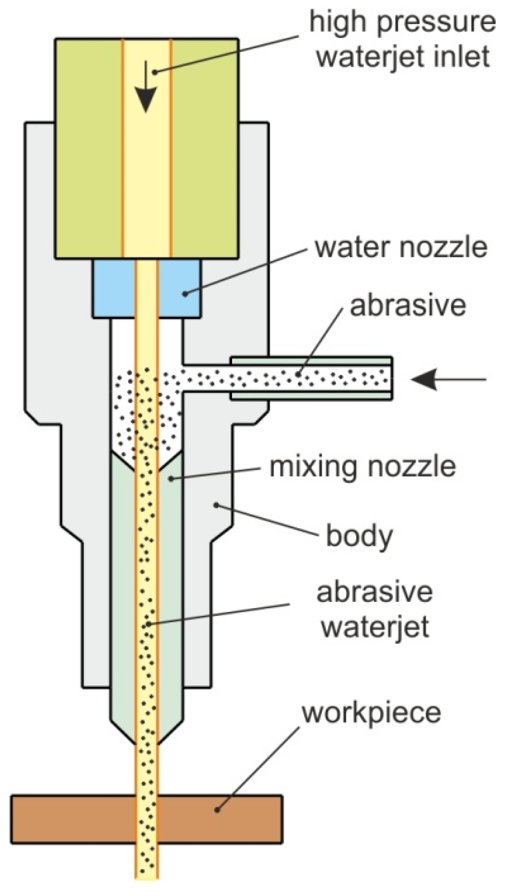
The basic element of the head of AWJ machines is the nozzle, which determines the quality and efficiency of the cutting process [62]. The structure of a typical AWJ nozzle is shown in Figure 4. Water jet cutting heads usually use ruby nozzles, which, under optimal processing conditions, ensure a period of proper operation up to 100 h. Sapphire nozzles are rarely used for AWJ cutting due to their rapid wear. Ruby or diamond nozzles have a service life of up to 100 and up to 2000 h, respectively, under WJ cutting conditions. In the micro abrasive water jet (μAWJ) technique, the diameter of the working stream is up to 0.1 mm. Meanwhile, the outlet diameter of the water jet nozzle is from 0.18–0.4 mm. The small diameter of the nozzle enables cutting curved shapes with a minimum radius of rounding of approximately 0.1 mm. Depending on the type of material and the size of the cut shape, the cutting tolerance is ±0.01 mm. Higher speed of the water jet increases the accuracy of cutting and cutting efficiency, while reducing water and abrasive consumption.
During AWJ cutting of CFRP composites, the cut edge is slightly damaged by the abrasiveness or becomes wet, which can cause the fibres to detach from the matrix [63]. AWJ cutting is recommended for processing brittle composite materials. The edges of the cut elements, unlike high-energy processing methods (e.g., laser, plasma), do not undergo thermal deformation and are not subject to structural changes caused by temperature because the water temperature during material separation does not exceed 40 °C. The advantages of high-pressure WJ cutting are that there is no need to sharpen the cutting tool and low deformations of the workpiece is observed. The high quality of the cut surface, with no burrs, makes the WJ and AWJ cutting techniques effective for use for processing FMLs. Delamination in water jet cutting is caused by the deposition of abrasive particles at the interface of two different materials and water wedging and shock waves in the initial phase.
The problem that needs to be overcome is the AWJ treatment of composite materials composed of very soft and hard layers [51]. With the increase in the difference in hardness between the layers, the level of difficulty in water cutting increases, related to ensuring the appropriate surface quality on the entire surface of the cut. The water jet passing through the soft layer hits the hard layer and is partially reflected from it, penetrating the cut edge of the soft material. Doluk et al. [64] confirmed the possibility of using an AWJ for cutting composite sandwich structures (aluminium alloy + CFRP based on epoxy resin). It was determined that the jet pressure is the key parameter influencing the quality of the cut surfaces.
Monoranu et al. [65] compared conventional milling and the AWJ to machine CFRP laminates and discovered that the AWJ specimens have higher surface roughness than conventional milled specimens. The difference was considered to be statistically significant (p = 0.05). Surface morphology analysis of AWJ-machined samples revealed considerable damage. Pits and transverse micro-fractures in the jet direction were observed along the initial damage zone at the jet entrance.
Alberdi et al. [62] investigated the impact of the AWJ process parameters on affected cut quality (taper and surface roughness) of two CFRP composite materials of varying thicknesses. The conclusion is that the machinability index of various composite materials varies greatly, necessitating separate investigations. To compare the machinability of different metals, the machinability index is utilised. For different cutting techniques, the machinability of two or more metals may change.
Demiral et al. [66] investigated the damage caused by AWJ cutting on a CFRP cross-ply laminate. They concluded that tensile matrix cracking started when the cutting of AWJ particles started, causing debonding from the top interlayer to the lower layers in a row. Furthermore, the fibre degradation was restricted to only the top-most layer. The low cutting speed of the particles causes layer damages to be more distributed along with the laminate thickness. As the impact angle increases, cutting the laminate gets more difficult due to the abrasive particles’ inability to cut it easily.
The effects of AWJ machining on carbon nanotube-reinforced aluminium alloy AA7475 composites were investigated by Kumar et al. [67]. According to the findings of this study, the machining tests on 9% carbon nanotube (CNT) composites revealed, that, as the proportion of CNT increases, the surface and mechanical roughness increases, requiring a higher abrasive flow rate to remove material. The abrasive flow rate will have the greatest impact on the multi-response performance index if the CNT composite is 3%. The traverse feed will significantly impact the CNT composite if it is 6%. Flow rate and water pressure can considerably affect surface roughness and mechanical roughness. Finally, 9% CNT-reinforced composites are stronger, wear-resistant and easier to machine when the abrasive flow rate and parameters are optimised.
Asawthnarayan et al. [68] investigated the effect of abrasive friction nanographene on the wear behaviour of glass–epoxy composites under different conditions. In the composites studied, wear volume loss was considered to be a linear function of abrasion load and the composition. Furthermore, abrasion wear resistance was observed to be better with 1 wt% nanographene than with more significant loadings of the same nanofiller. Moreover, the composites’ hardness, good mechanical characteristics and enhanced degree of crystallinity resulted in good abrasion wear behaviour. According to the frictional study, when nanographene is added at lower pressure, the coefficient of friction (COF) drops at first, but the composites reverse their behaviour when the pressure is increased.
Shunmugasundaram et al. [69] used the Taguchi technique to improve machining parameters for cutting aluminium-based metal matrix composites using an AWJ machining process. Water pressure, abrasive flow rate and traverse velocity were chosen as input parameters for machining, with material removal speed and surface roughness as output responses. The response analysis by means of signal-to-noise (S/N) ratio revealed that traverse speed has a more significant influence on material removal rate than the other two machining parameters.
The impact of process variables, including water pressure, abrasive flow rate, feed rate and stand-off distance on the properties of the cut surfaces of the Ti6Al4V alloy during AWJ, have been investigated by Abushanab et al. [70]. In comparison to other process parameters, the abrasive flow rate contributed 29.32%, and the stand-off distance contributed 61.77% to control surface roughness.
In the AWJ cutting of stainless steel 304, Karthik et al. [71] aimed to optimise the machining settings where the water jet pressure, feed rate and abrasive flow rate are the key input parameters. They discovered that water pressure and feed rate have the most significant influence on material removal rate, with greater feed rates and lower abrasive flow rates producing the smallest kerf top width.
Joel et al. [72] adopted response surface methods to calculate abrasive feed machining parameters in order to optimise the machining operational parameters of AWJ cutting on AA6082. The actual and anticipated response surface values of AA6082 for hardness, metal removal rate and surface roughness are assessed using the quadratic equation. This study successfully overcame the optimisations of AA6082 utilising response surface methodology. The effect of material removal rate of 0.1548 g/s, surface roughness of 4.90 µm in Ra and a hardness of 92.86 BHN were substantially closer to optimal values in a confirmatory experiment using a combination of ideal parameters projected for AA6082 for verification.
To cut the tungsten plate for the fusion device, Wang et al. [73] employed a pre-mixed abrasive water jet, as depicted in Figure 5. It was concluded that the transverse speed significantly impacted the surface roughness. As a result, lowering the transverse speed reduces surface roughness and improves section quality. The surface roughness was less affected by the jet pressure. Increasing the jet pressure can enhance the overall section quality by increasing the depth of the smooth area.
The abrasive water jet is proven to be an economical and efficient process for machining of metal-based and polymer-based composite materials in various manufacturing industries [74]. The main advantage of the AWJ to other cutting processes is the reduction of thermal defects during machining. Thus, carbon fibre-reinforced thermoplastics (CFRTPs) and CFRPs can be machined without matrix removal [75,76,77]. Previous studies [78] have confirmed the presence of higher fatigue strength in the AWJ machined and peened surfaces. Srinivas and Babu [79] have studied the jet penetration ability on SiC particles in MMCs with an abrasive water jet. The most influencing factors during the cutting of these types of composites is the traverse rate and water jet pressure. The increase in the hardness of the material led to a decrease in the contribution of the pressure of the water jet. Cutting performance in terms of kerf formation, surface morphology and kerf wall features of CFRP samples have been studied by Dhanawade and Kumar [80]. Based on the response surface methodology (RSM), they found that surface roughness decreases with the decrease in the traverse rate and stand-off distance and increase in the hydraulic pressure and abrasive mass flow rate. CFRP surfaces machined by an AWJ are of better quality as compared to the surfaces machined by a diamond edge cutter. El-Hofy et al. [75] investigated jet pressure, stand-off distance and feed rate in terms of the kerf taper, the bottom kerf width and surface characteristics in the AWJ cutting of two lay-up configurations of multidirectional CFRP laminates. Based on the analysis of variance it was found that for a smaller kerf taper, it is recommended to use high pressure, small stand-off distance and high feed rate. On the other hand, the kerf width at the top of the cut increases with water jet pressure and stand-off distance and decreases with feed rate.
The main parameter influencing the conicity of the cut is the combination of the stand-off distance and the feed rate. Sambruno et al. [81] examined the influence of cutting parameters on the kerf taper generated during water jet machining of a thin-walled thermoplastic composite material (carbon/thermoplastic polyurethane, C/TPU). Analysis of variance analysis (ANOVA) showed that water pressure and feed rate are the most significant parameters in AWJ cutting. The walls of the slot become more vertical at high pressures and low feed rates. This is due to the greater concentration of energy affecting the processed composite, which translates into greater material removal. The results of Sambruno et al. [81] are in line with the findings of Dhanawabe et al. [82], who used ANOVA to determine the effect of processing parameters on the taper angle. They found that the most influential parameter on the conicity of the cut was hydraulic pressure. Increasing this parameter increases the kinetic energy of the water jet and, thus, reduces the conicity of the cut.
Abrasives play a vital role in machining operation by the AWJ machine tool [83,84]. An experiment shows that the depth of the cut increases with an increase in the hardness of the abrasives [85]. The influence of process parameters on kerf taper in AWJM of a Kevlar epoxy composite was studied by Kumar and Kant [86]. Examination of the influence of four process parameters (stand-off distance, abrasive flow rate, traverse speed and water pressure) on kerf taper angle led to a conclusion that the most important process parameters significantly affecting the kerf taper angle are the traverse speed of the water pressure. Kerf taper of a Kevlar 49 epoxy composite machined by AWJM is significantly influenced by the water pressure and traverse speed [87].
Thakur et al. [88] investigated delamination factor measured as a ratio of the maximum width of cut and actual width of cut at the entry and exit side of a hole produced on a hybrid carbon/glass composite by changing the traverse rate, stand-off distance and water jest pressure. It was found that stand-off distance was the most effective parameter for the delamination factor at the entry of the hole, while traverse rate was the most effective parameter for the delamination factor at the exit of the hole. Li et al. [89] investigated the hole cutting on CFRP laminates using both AWJ and WJ machining. It was found that limited entry/exit delamination was found in AWJ hole cutting compared to the pure WJ. High jet pressure or low traverse rate is responsible for diameter offset in the AWJ cutting process [90].
4. Plasma Cutting
Plasma is a highly ionised gas in the form of a beam ejected from a plasma nozzle at a speed close to the speed of sound wave propagation in air [91] or even higher. The plasma beam temperature depends on the intensity of the electric current and the type of plasma gas and amounts to between 10 [92] and 30 [93] thousand Celsius. The flow of plasma gas through the glowing electric arc causes its ionisation, and due to the high concentration of power, a plasma stream concentrated in the nozzle is generated [94]. A highly concentrated plasma arc of high temperature and high kinetic energy, glowing between the non-consumable electrode and the workpiece, ejects the metal from the cutting kerf [95]. Plasma cutting is not widely used in the processing of composite materials. Studies by Iosub et al. [96] show that it is possible to plasma cut sandwich composites composed of aluminium layers separated by a polyethylene core. However, due to the much lower melting point of polyethylene, it is necessary to use high cutting speeds to minimise the exposure of the polyethylene to the plasma arc.
5. Electromachining
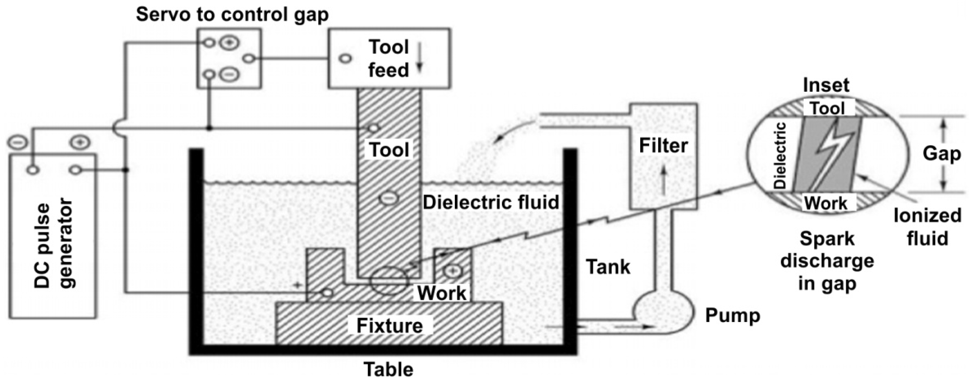
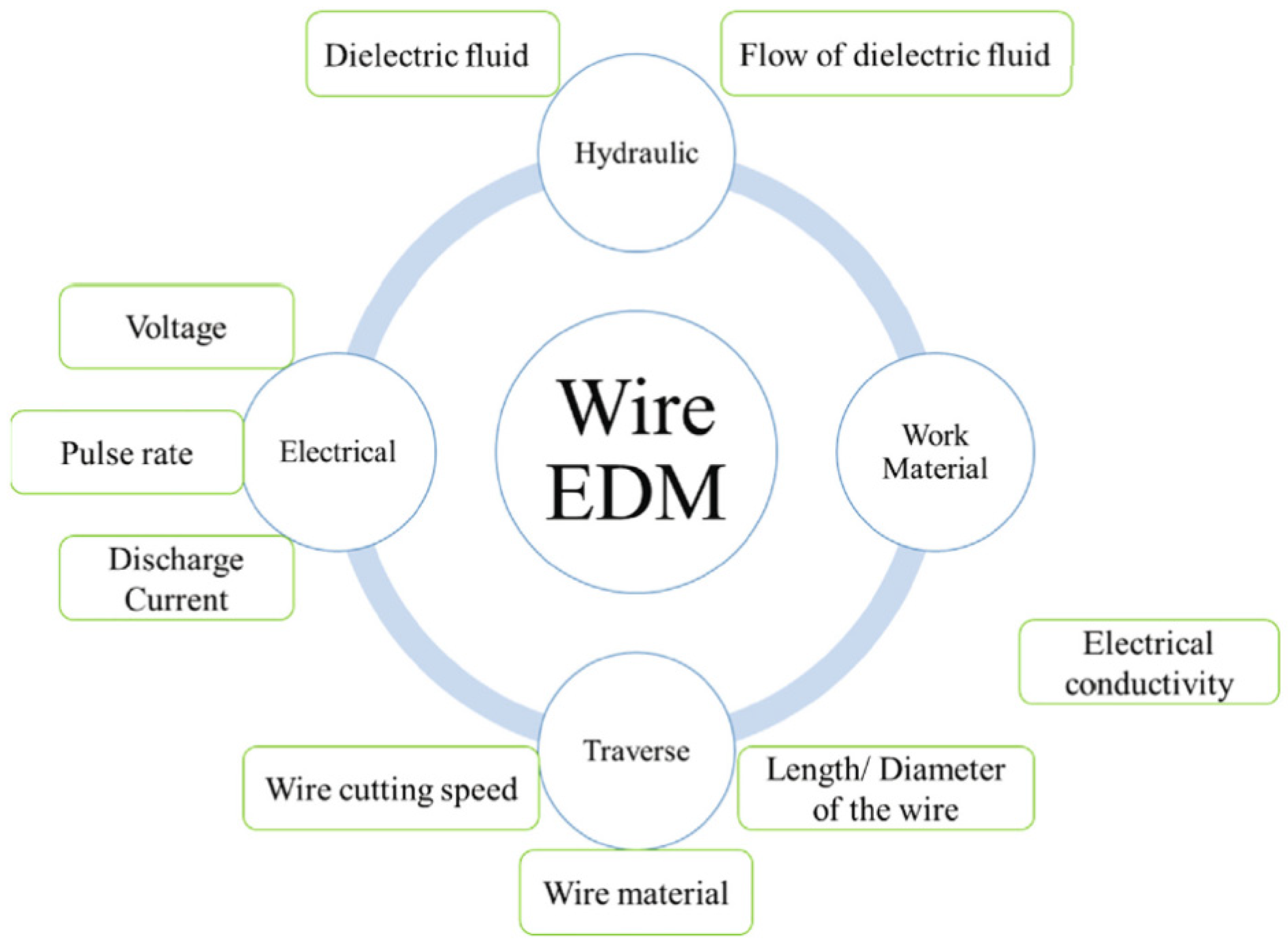
Electrical discharge machining (EDM) as a schematic is illustrated in Figure 6. Developed in the late 1940s [97], it is one of the most extensively used manufacturing technologies for manufacturing complex products in roughing and finishing operations [98]. EDM is an alternative to machining and is used to drill holes, primarily in metal matrix composites. EDM and wire electrical discharge machining (WEDM) are used to form composite matrices with complex internal surfaces, with an accuracy of 2 μm [99,100]. EDM was established based on removing material from a workpiece using a dielectric fluid and a series of repetitive electrical discharges among tools called electrodes and the workpiece [101]. The electrode moves toward the workpiece until the space between them is small enough to ionise the dielectric with the impressed voltage. Short-duration discharges are formed in a liquid dielectric gap between the tool and the workpiece. Electrical discharges from the tool and workpiece erode the material, thereby removing it [102,103]. Parameters controlling the performance of the WEDM method are shown in Figure 7. Controlling of the discharge current is crucial while machining FMLs. A high current results in an intensified heat generation at the work surface, which can either elongate the continuous fibres, melt or char the binder and cause debonding between the matrix and the binders. At larger pulse duration, the electrode wear is low and material removal rate is high. However, large pulse duration leads to high surface roughness of the cutting edge [104].
During EDM, the allowance is removed from the composite material as a result of the phenomena accompanying electrical discharges (heat release, temperature rise, evaporation, melting and tearing of the material) in the area between the electrode and the workpiece [106]. EDM and WEDM reduce the occurrence of post-machining stresses in the workpiece. The problems accompanying WEDM cutting process are, however, the low cutting efficiency and the formation of the undesirable so-called white layer on the treated surface [99], the thickness of which depends on the type of composite and the processing conditions. Ceramic composites with complex shapes can be electromachined as long as they have the appropriate electrical conductivity, which can be obtained by adding TiC, TiN or TiB2, to result in, for example, ZrO2-TiN, Si3N4-TiN, B4C-TiB2. The resistance of materials subjected to EDM cutting should not exceed 100 Ω·cm.
Current trends in WEDM of metal–matrix composites (MMCs) has been provided by Gore and Patil [100]. Due to low accuracy, poor machineability, huge amount of tool wear and poor surface quality, the conventional machining processes (i.e., drilling, milling) are not recommended for cutting MMC’s. Instead of conventional machining, the authors [107,108,109,110] recommended non-conventional machining processes for the cutting of MMCs.
The use of WEDM to cut polymer composite materials (PCMs) has been investigated by various researchers [111,112,113] who found that the conductivity of PCMs is limited. High temperature and lack of effective cooling can lead to the destruction of the resin at the edges of the holes in PCMs. The problems with the quality and accuracy of the holes in the poorly conductive material can be overcome by regulating the conductive layer over the non-conductive PCM [114,115]. Ablyaz et al. [113] found that pulse duration of voltage and their interactions are the significant factors affecting the machining of the PCMs.
Recently, Abdallah et al. [116] analysed the cutting process of undirectional CFRPs using WEDM to study the effects of pulse-on time, pulse-off time, gap voltage and current on the top and bottom cut-width (kerf), workpiece edge damage and material removal rate (MRR). It was found that pulse-off time and current were statistically important parameters in terms of material removal rate. However, the only factor affecting cut-width on the top surface was current.
Dutta et al. [117] investigated the CFRP composite cutting using a modified version of WEDM. The problems with deviation in machining path and incomplete cut have been overcome by using metal plates (H13 steel) as assisting-electrodes. The results showed that increasing the current reduced the cutting time while keeping all other parameters constant. WEDM with the aid of sandwich-assisting electrodes showed damages such as matrix cracking, fibre–matrix debonding and breakage of carbon fibres.
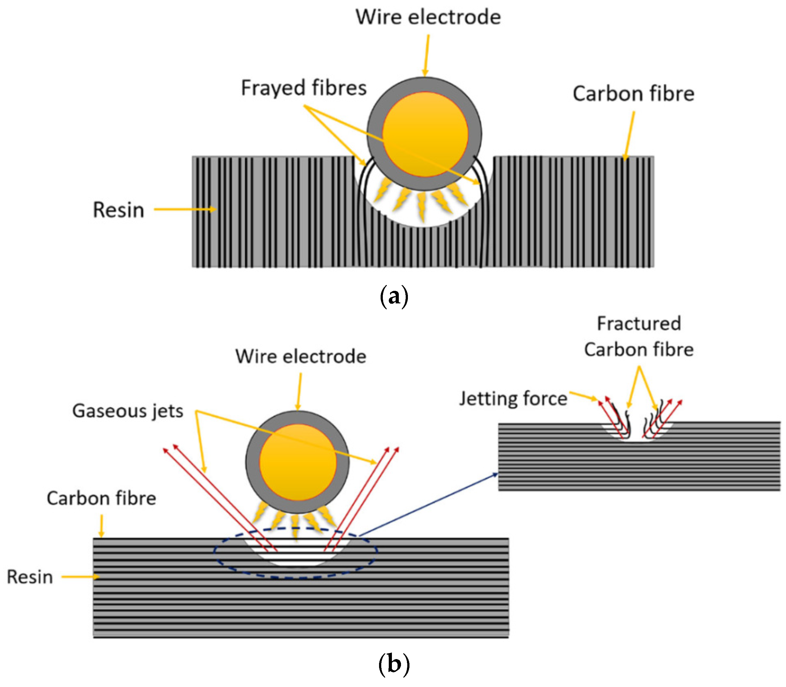
Abdallah et al. [118] studied the influence of operating parameters and cut direction (perpendicular and parallel to fibre orientation) when WEDM was used to cut unidirectional CFRP composites. Workpieces machined parallel to fibre direction (Figure 8a) were generally free of any major edge defects, in contrast to severe delamination observed on the bottom surfaces of specimens cut perpendicular to fibre orientation (Figure 8b). The higher electrical conductivity of the workpiece along the fibre length leading to greater discharge energies and, consequently, the maximum MRR. A ~16% increase in maximum MRR was achieved when machining parallel to fibre direction compared to cutting perpendicular to the fibres. WEDM of CFRP laminates conducted by Yue et al. [119] resulted in ~18% higher cutting speed due to the increased thermal conductivity of fibres in the axial compared to transverse orientation.
Sheikh-Ahmed [120] investigated the material removal mechanisms and surface delamination in EDM drilling of CFRP with respect to varying current and pulse-on time. It was found that pulse-on time had a major effect on the resulting degree of HAZ and hole tapering while delamination was significantly influenced by discharge current.
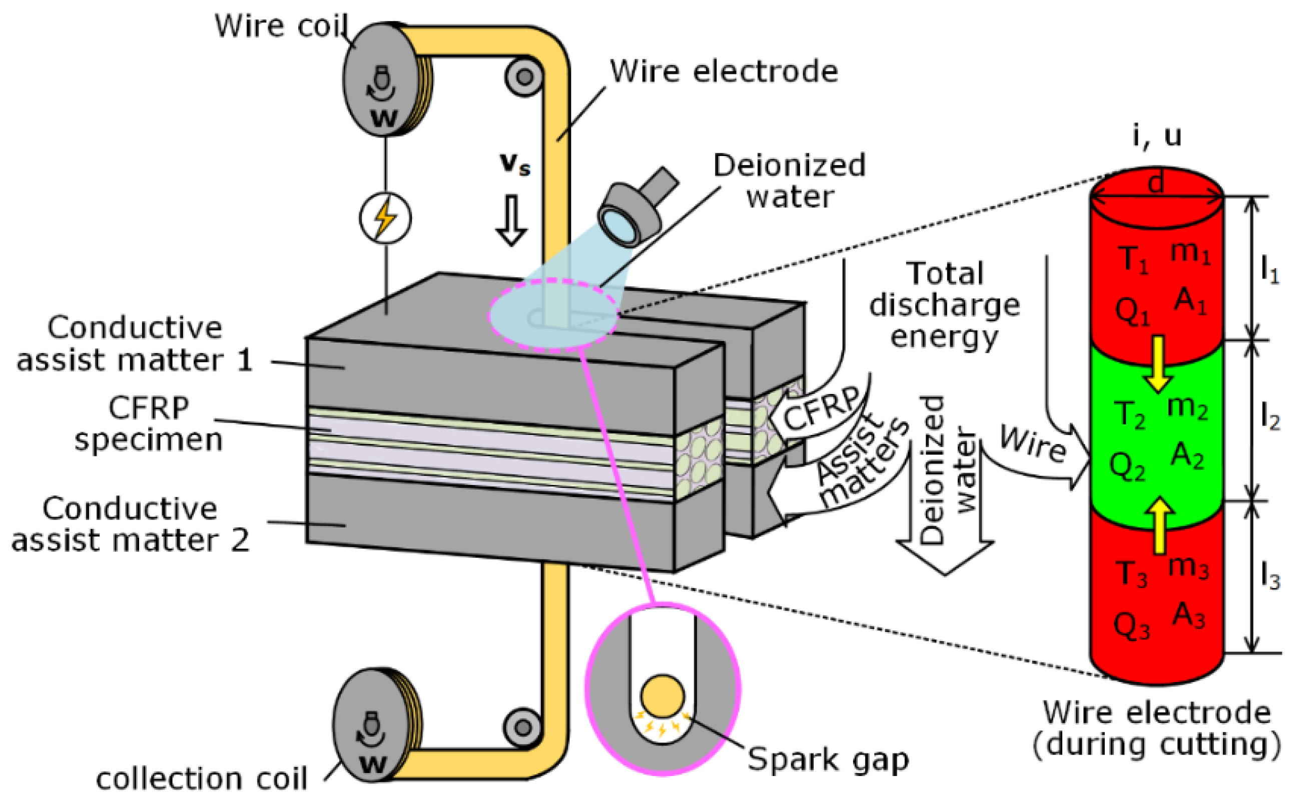
Wu et al. [121] proposed a preheating-assisted WEDM technique (Figure 9) for machining undirected CFRP by sandwiching the composite workpiece between carbon steel plates, which acted as assisting layers. Both analytical modelling and experimental results showed that the method proposed can effectively cut 4-mm-thick CFRPs (32 layers of prepreg plies with the same carbon fibre orientation) by removing uncut epoxy resin via heating the wire electrode based on the introduced conductive assist matters. It was found that the intense spark discharges occurring at the metallic layers were sufficient to melt the low conductivity resin matrix of the CFRP.
6. Ultrasonic Cutting
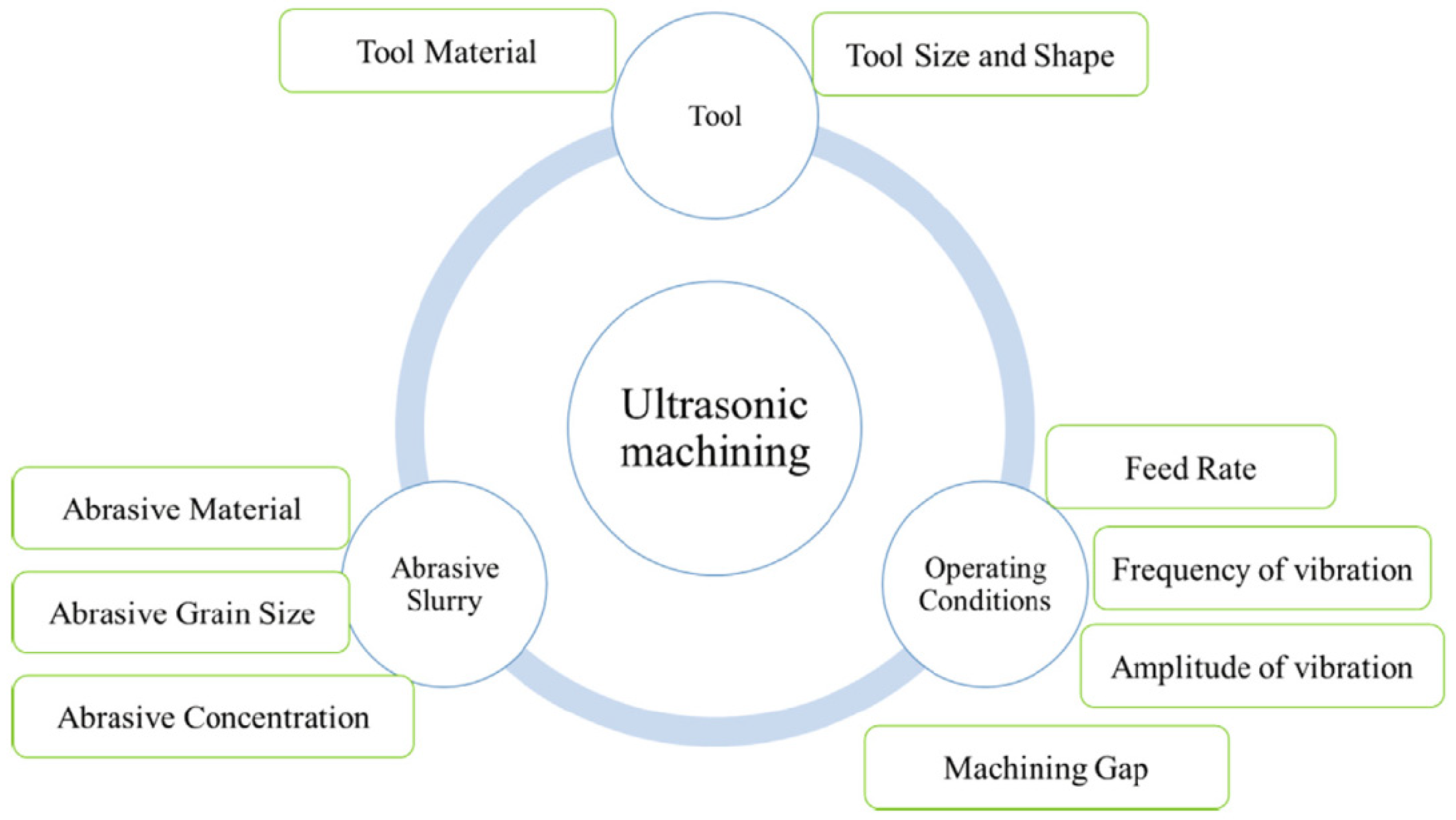
Ultrasonic treatment is an erosive treatment with abrasive grains freely suspended in a working fluid and receiving energy from a vibration source. The task of the working fluid is to transfer ultrasonic waves, remove particles of the crushed material from the treatment zone and cool the treatment zone [122,123]. The accuracy of ultrasonic machining, mainly used for drilling holes in ceramics and composites, depends mainly on the grain size of the abrasive, the vibration frequency (19–25 kHz) and vibration amplitude (10–50 μm) of the tool. AS proposed by Hahn et al. [124], the optimal ultrasonic cutter requires 70% less cutting force than the conventional cutter to cut a ceramic composite material. The cutting surface is much cleaner with no crack and delamination compared with the application of the conventional (titanium, aluminium or stainless steel) cutter. Many researchers have investigated the frequency characteristics of various ultrasonic machines considering the geometrical characteristics of the horn; however, they did not even consider the various geometrical design variables simultaneously [125,126,127]. Ultrasound assistance dramatically reduces the creation of a built-up edge, decreases the cutting forces and lowers the process heat [128]. For very fine shapes in electrically non-conductive materials and conductive materials, a micro ultrasonic machining (µUSM) process was developed where a micro-sized tool is used during the machining [129]. The parameters affecting ultrasonic machining are shown in Figure 10.
A variety of ultrasonic machining are used to make holes with a drill using Rotary Ultrasonic Machining (RUM). A high number of typical and widely utilised difficult-to-cut materials have been successfully machined by RUM, such as the SiCp/Al composite [130], the CFRP/Ti [131] and the CFRPs [23,132]. The RUM is most often used for machining CFRP composites and has many advantages compared to drilling holes with the conventional methods, i.e., lower cutting resistance, lower surface roughness of the machined surface, less tool wear and a limited delamination.
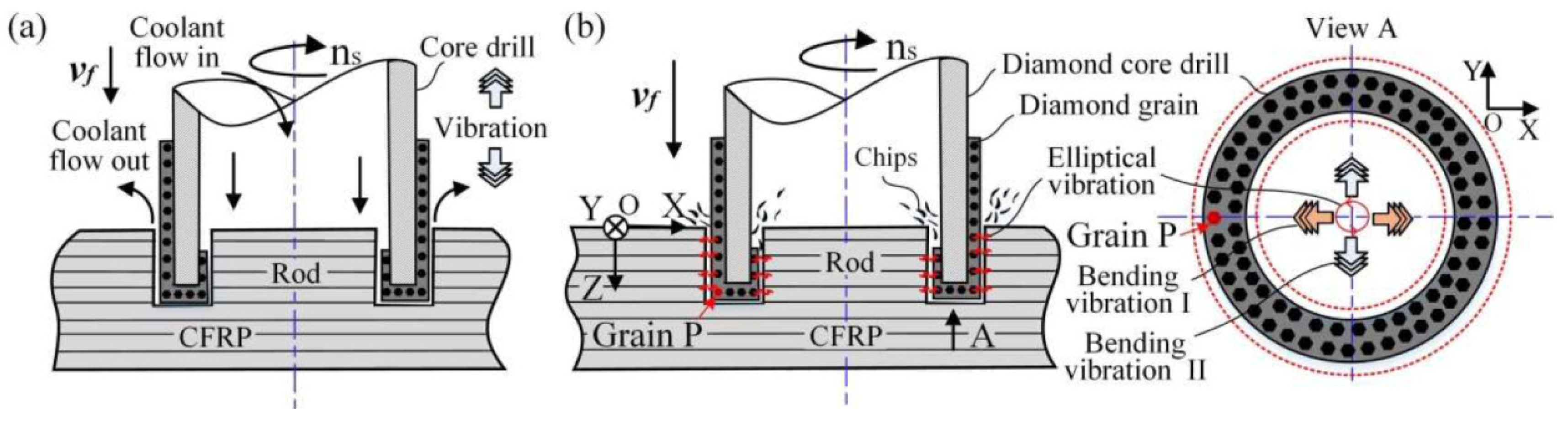
Baraheni and Amini [133] determined the effect of drilling and material variables comprising feed rate, cutting velocity, plate thickness and ultrasonic vibration on delamination and thrust force during rotary ultrasonic machining (Figure 11a) of the CFRPs. Based on the ANOVA results it was concluded that the lowest delamination is observed in lower feed rate and cutting velocity by applying ultrasonic vibration on the thinner composite laminate.
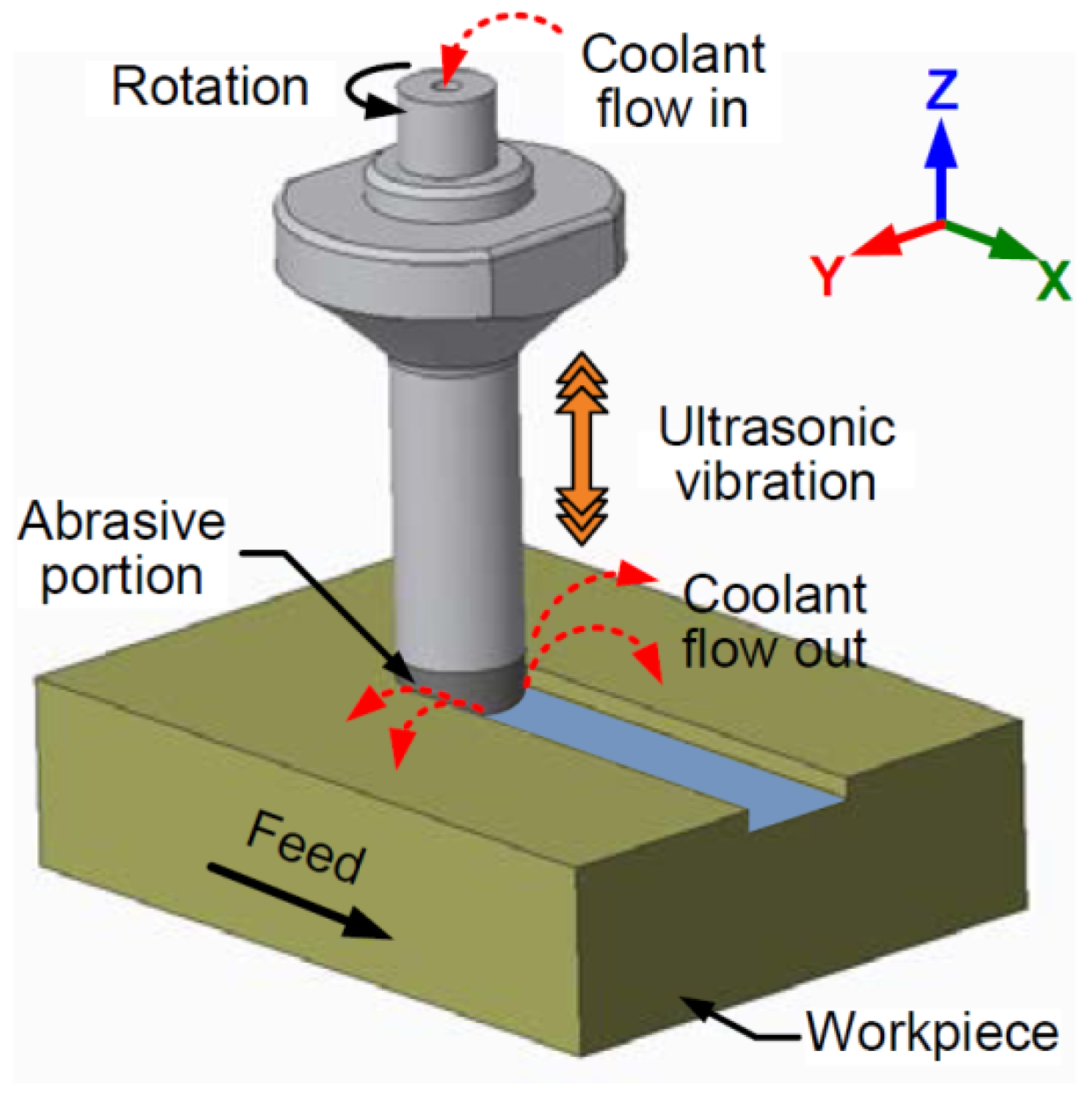
When cutting using Rotary Ultrasonic Surface Machining (RUSM), which combines both ultrasonic machining and surface machining processes, a cooling lubricant (liquid or cold air) is supplied to the machining area (Figure 12). For the first time, a comparison between RUSM and conventional surface grinding (CSG) of CFRPs and the effect of process parameters on surface roughness, torque and axial and infeed-directional cutting forces was conducted by Ning et al. [135]. It was found that RUSM exhibited larger surface roughness compared with CSG resulting from the occurrence of surface damages induced by the vertical ultrasonic vibration.
Recently, research focus has shifted to the vibration-assisted drilling (VAD) of FRC materials. Cutting mechanisms of vibration-assisted drilling and conventional machining are fundamentally different from each other. VAD has many unique characteristics such as impacting, separating, changing speed and changing angle during the drilling process [136]. According to Debnath et al. [136], there are four different VAD processes: RUM, vibration-assisted twist drilling (VATD) [137,138], ultrasonic drilling (UD) [139] and rotary ultrasonic elliptical machining—RUEM (Figure 11b) [140]. Rotary-mode ultrasonic drilling (RMUD) is a non-contact-type machining process in which the rotation of the workpiece takes place. Debnath et al. [136] conducted research on drilled holes in lass-epoxy laminates to improve the quality (in terms of push-down type of delamination and hole-edge quality) and the productivity (in terms of number of holes per hour). The major contribution of their investigations was the development of a novel method of making clean-cut damage-free holes in the FRC laminates.
Applying vibration may reduce the amount of thrust force, delamination and wear of the tool [141]. When cutting GFRPs, applied frequencies are lower than 60 Hz and applied vibration amplitudes are up to 20 μm [142]. When cutting CFRPs, the increase in cutting temperature leads to a change of powder chips into chips as a result of resin melting, thus, causing the resin to degrade when the cutting temperature exceeds its glass transition temperature [143]. Xu et al. [144] pointed out that in view of thermal conductivities of Ti (i.e., 7.99 W/mK) and CFRP (i.e., 1.0 W/mK) and the cutting heat developed in drilling cannot be substantially released by the workpiece and chips, resulting in great heat concentrating around the hole wall. The temperature reduction in the cutting zone can be achieved by cooling with the minimum quantity liquid (MQL), air or coolant liquid. Helmy et al. [145] proposed different fluid delivery methods on ultrasonic assisted machining of multidirectional CFRPs using diamond abrasive tools. It was found that the use of mist coolant caused an increase in cutting forces compared to flood coolant because of insufficient removal of dust and heat from the cutting zone.
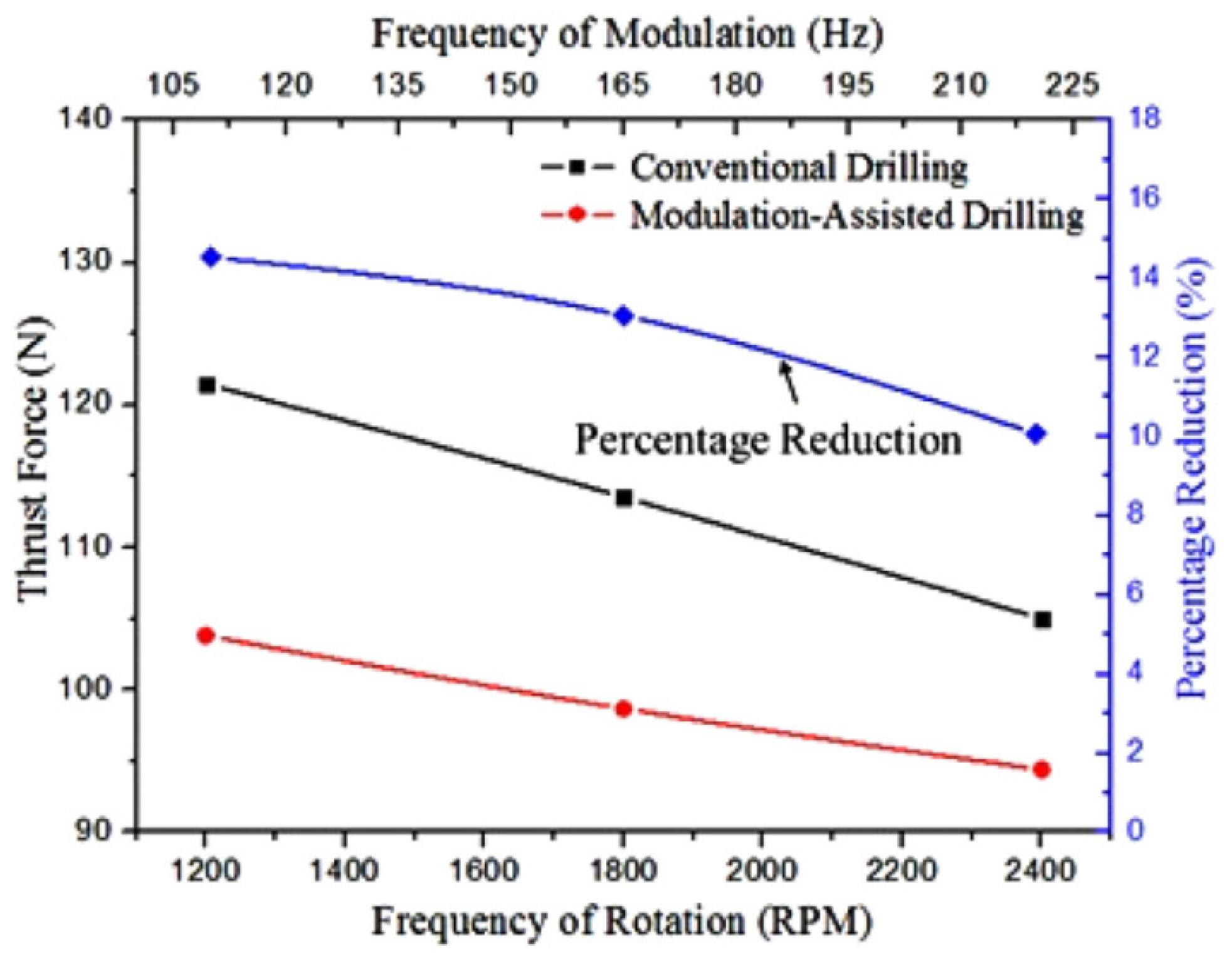
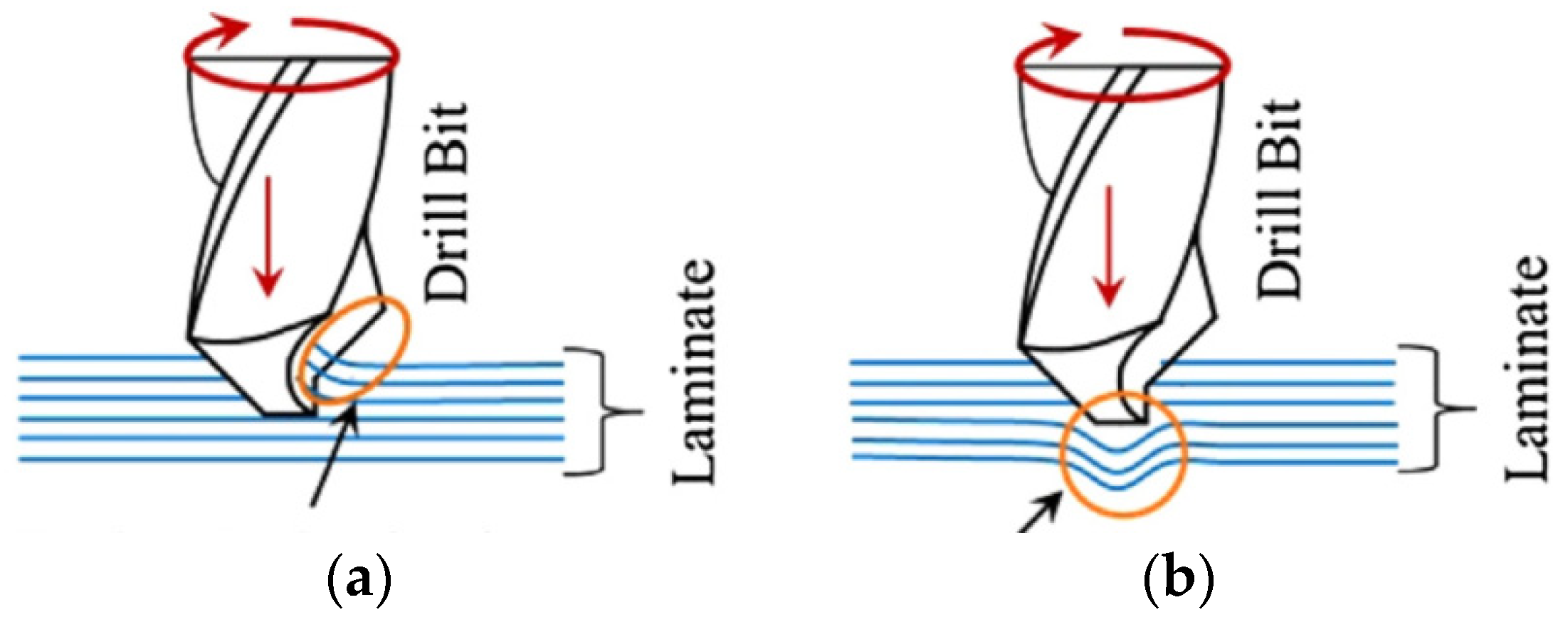
Debnath and Singh [146] proposed low-frequency modulation-assisted drilling (MAD) for carbon-epoxy composite laminates. One of the striking features of the MAD is that the drill and the laminate engage and disengage alternatively during processing. This is one of the plausible reasons of the lower value of average force during MAD as compared to the conventional drilling (Figure 13). Two types of delamination are formed during the drilling of composite laminates, peel-up (Figure 14a) and push-down (Figure 14b) delamination that occur at the entry and exit side of the hole, respectively. The other defects connected with the drilling of composite laminates are shown in Figure 15. Review of the current literature on the drilling-induced delamination for composite laminates has been provided by Geng et al. [9]. Apart from the deterioration of the hole surface quality, the delamination deteriorates the properties of the composite. It has also been established that the push-down delamination is more prone to in-service failure than the peel-up delamination [146]. MAD process allowed to decrease the delamination factor as a ratio of hole and damage area and hole area.
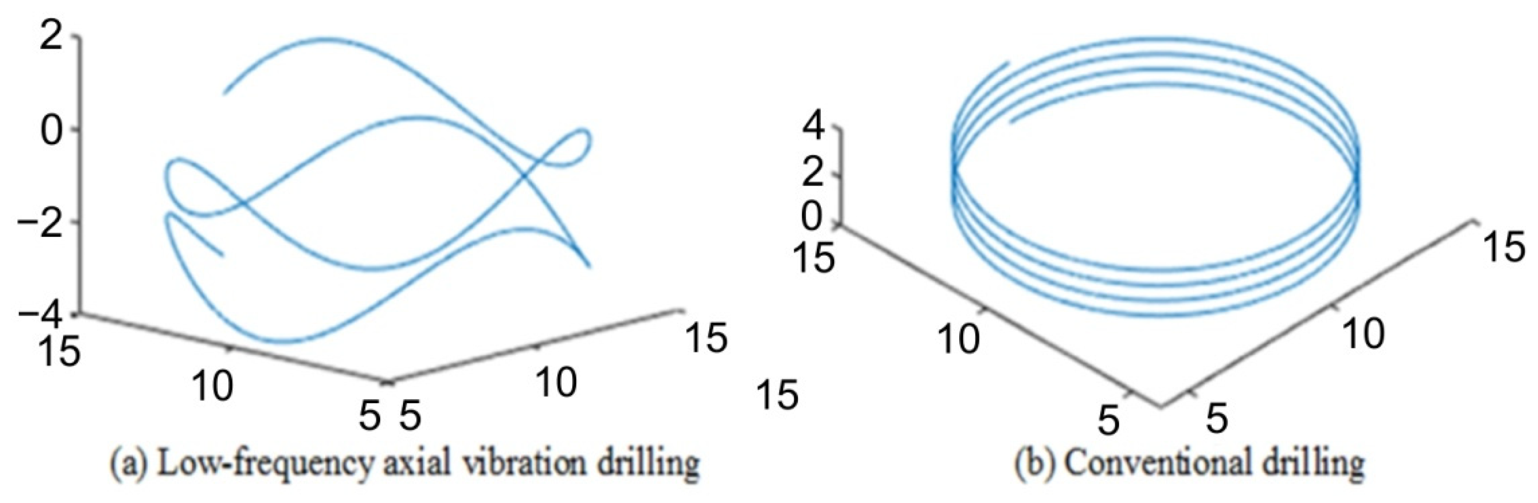
Dahnel et al. [148] applied the ultrasonic-assisted drilling (UAD) process to drill CFRP/Ti laminates by single-shot with cutting fluid. The tool wear obtained in UAD including major edges chipping, abrasive wear and titanium adhesion can be effectively restrained in the UAD process. Shao et al. [149] applied the UAD to drilling CFRP/Ti laminates without cooling, which achieved higher hole quality and productivity compared with conventional drilling (CD). Cong et al. [150] found that the variable feed rate, compared with the constant feed rate, can achieve a better effect during ultrasonic drilling of CFRP/Ti laminates. Zheng et al. [147] proposed low-frequency (LF) vibration drilling (Figure 16) combined with a thin-wall diamond trepanning bit to achieve the constant feed rate drilling of a Al2O3/GFRP laminated composite plate. It was found that compared with the CD, low-frequency axial vibration drilling can achieve the constant feed rate drilling of GFRP with better drilling quality. LF axial vibration drilling is a promising technology for drilling difficult-to-cut materials [151,152,153,154,155], which forms intermittent chips and promotes relative vibration between the workpiece and the tool. The LF vibration drilling reduces the delamination defect and the cutting force [156,157].
Longitudinal torsional coupled rotary ultrasonic-assisted drilling (LTC-RUAD) technology using a tapered drill-reamer is introduced to improve the surface finish of the hole wall of CFRPs induced by large thrust force and torque during CD [158]. Compared with CD, the torque and maximum average thrust force were reduced by approximately 40% and 30%, respectively. The surface roughness of the drilled hole with LTC-RUAD was better than that obtained by adopting the conventional drilling process under the same process parameters.
CFRP is the most studied material in vibration-assisted drilling. Arul et al. [159] and Zhang et al. [160] studied the effect of process parameters on the delamination when vibratory drilling of CFRPs with the thickness t = 4.0–4.8 mm. Makhdum et al. [161] cut the CFRP in ultrasonically-assisted drilling. The holes drilled with UAD show better circularity, improved surface roughness and result in a lower delamination area in UAD when compared to CD. Debnath and Singh [146] and Pecat and Brikeksmeier [162] drilled CFRPs using low frequency modulation-assisted drilling and low frequency vibration-assisted drilling, respectively.
Chen et al. [163] developed two-dimensional rotatory ultrasonic combined with electrolytic generating machining, which organically combined electrolysis and an ultrasonic effect with a high-speed rotating electrode. The method proposed was tested when cutting ceramic-reinforced metal matrix materials. The authors provided and successfully verified a new concept for high-performance machining of difficult-to-cut materials.
7. Summary
Due to the large variety of composite properties, determining the possibility of cutting a composite material with a specific method requires an individual approach. The basic criterion is the required accuracy of the cut surface and the physical properties of the composite, which determine the technical feasibility of cutting with a given method. In the case where the composite has a direction-oriented sandwich structure, the cutting efficiency depends on the orientation of the cut line and the stacking order of the layers. The most important observations from the review presented in this article are as follows:
- The main limitations in conventional machining of metal matrix composites are the difficulty in ensuring the integrity of the treated surface against cracking, the increase in machining costs due to high tool wear, long machining cycle and low machining efficiency;
- Applying ultrasonic vibration to the cutting tool reduces both the frictional force between the workpiece and the tool, the cutting force required and the stress on the workpiece;
- Current investigations are focused on the optimisation of machining parameters and the development of hybrid methods combining ultrasonic treatment with other methods, such as electromachining or electrosis;
- Conventional processing of PCMs by milling or drilling results in vibrations that cause the fibres to be pulled out, reducing the operational quality of products, especially in the aircraft industry. WEDM of PCMs is a potential candidate for the preparation of small parts with high accuracy;
- Requirements for the individualisation of equipment and machine performance to the specific composite material produces laser cutters with a different degree of automation, power of the laser source and size of the working area;
- Unconventional treatment methods such as chemical and electrochemical treatment are hazardous to the environment;
- Despite many disadvantages, such as thermal deterioration of the matrix material, composite processing techniques, such as laser cutting, plasma cutting, laser cutting and ultrasonic cutting, are considered beneficial when machining accuracy is not the primary concern.
Author Contributions
Conceptualization, T.T.; methodology, T.T. and S.M.N.; validation, T.T., S.M.N. and H.G.L.; formal analysis, T.T. and S.M.N.; resources, T.T. and S.M.N.; data curation, T.T., S.M.N. and H.G.L.; writing—original draft preparation, T.T. and S.M.N.; writing—review and editing, T.T., S.M.N. and H.G.L. All authors have read and agreed to the published version of the manuscript.
Funding
This research received no external funding.
Institutional Review Board Statement
Not applicable.
Informed Consent Statement
Not applicable.
Data Availability Statement
Not applicable.
Conflicts of Interest
The authors declare no conflict of interest.
References
- Ciałkowska, B.; Wiśniewska, M.; Andrzejewski, P. Problematyka przecinania wybranych materiałów kompozytowych struną zbrojoną trwale. Zesz. Nauk. Politech. Rzesz.—Mech. 2017, 34, 457–468. [Google Scholar] [CrossRef] [Green Version]
- Kubit, A.; Trzepieciński, T.; Krasowski, B.; Slota, J.; Spišák, E. Strength analysis of a rib-stiffened GLARE-based thin-walled structure. Materials 2020, 13, 2929. [Google Scholar] [CrossRef] [PubMed]
- Trzepieciński, T.; Najm, S.M.; Sbayti, M.; Belhadjsalah, H.; Szpunar, M.; Lemu, H.G. New advances and future possibilities in forming technology of hybrid metal–polymer composites used in aerospace applications. J. Compos. Sci. 2021, 5, 217. [Google Scholar] [CrossRef]
- Golzar, M.; Poorzeinolabedin, M. Prototype fabrication of a composite automobile body based on integrated structure. Int. J. Adv. Manuf. Technol. 2010, 49, 1037–1045. [Google Scholar] [CrossRef]
- Bałon, P.; Świątoniowski, A.; Rejman, E.; Kiełbasa, B.; Smusz, R.; Szostak, J.; Kowalski, Ł.; Bałon, N.; Cieślik, J. Zastosowanie cienkościennych konstrukcji integralnych w lotnictwie na przykładzie projektu SAT-AM. Zesz. Nauk. Politech. Rzesz.—Mech. 2020, 92, 5–17. [Google Scholar] [CrossRef]
- Kaczorowska, K.; Jakubowski, M. Wykorzystanie metod przyrostowych w budowie i obróbce elementów kompozytowych o złożonej geometrii. Zesz. Nauk. Politech. Rzesz.—Mech. 2020, 92, 77–93. [Google Scholar] [CrossRef]
- Cicco, D.D.; Taheri, F. Use of a simple non-destructive technique for evaluation of the elastic and vibration properties of fiber-reinforced and 3D fiber-metal laminate composites. Fibers 2018, 6, 14. [Google Scholar] [CrossRef] [Green Version]
- Prince, K. Composites win over sports market. Reinf. Plast. 2002, 46, 48–51. [Google Scholar] [CrossRef]
- Geng, D.; Liu, Y.; Shao, Z.; Lu, Z.; Cai, J.; Li, X.; Jiang, X.; Zhang, D. Delamination formation, evaluation and suppression during drilling of composite laminates: A review. Compos. Struct. 2019, 216, 168–186. [Google Scholar] [CrossRef]
- Subramanian, K.; Cook, N.H. Sensing of drill wear and prediction of drill life. Trans. ASME J. Eng. Ind. 1997, 99, 295–301. [Google Scholar] [CrossRef] [Green Version]
- Stone, R.; Krishnamurthy, K. A neural network thrust force controller to minimize delamination during drilling of graphite-epoxy laminates. Int. J. Mach. Tools Manuf. 1996, 36, 985–1003. [Google Scholar] [CrossRef]
- Safari, M.; De Sousa, R.A.; Fernandes, F.; Salamat-Talab, M.; Abdollahzadeh, A. Creep age forming of fiber metal laminates: Effects of process time and temperature and stacking sequence of core material. Materials 2021, 14, 7881. [Google Scholar] [CrossRef] [PubMed]
- Vieira, L.M.G.; Dobah, Y.; Dos Santos, J.C.; Panzera, T.H.; Campos Rubio, J.C.; Scarpa, F. Impact properties of novel natural fibre metal laminated composite materials. Appl. Sci. 2022, 12, 1869. [Google Scholar] [CrossRef]
- Ha, W.; Wang, L.; Liu, H.; Wang, C.; Yao, L.; Li, Q.; Sun, G. On impact behavior of fiber metal laminate (FML) structures: A state-of-the-art review. Thin-Walled Struct. 2021, 167, 108026. [Google Scholar]
- Bougdiri, I.; Giasin, K.; Mebrouki, T.; Zitoune, R. Effect of cutting parameters on thrust force, torque, hole quality and dust generation during drilling of GLARE 2B laminates. Compos. Struct. 2021, 261, 113562. [Google Scholar] [CrossRef]
- Bahonar, M.; Safizadeh, M.S. Investigation of real delamination detection in composite structure using air-coupled ultrasonic testing. Compos. Struct. 2022, 280, 114939. [Google Scholar] [CrossRef]
- Gong, Y.; Chen, X.; Zou, L.; Li, Z.; Zhao, L.; Zang, J.; Hu, N. Experimental and numerical investigations on the mode I delamination growth behavior of laminated composites with different z-pin fiber reinforcements. Compos. Struct. 2022, 287, 115370. [Google Scholar] [CrossRef]
- Wang, G.D.; Kirwa, M.S. Comparisons of the use of twist, pilot-hole and step-drill on influence of carbon fiber-reinforced polymer drilling hole quality. J. Compos. Mater. 2018, 52, 1465–1480. [Google Scholar] [CrossRef]
- Bonhin, E.P.; David-Müzel, S.; Alves, M.C.S.; Botelho, E.C.; Ribeiro, M.V. A review of mechanical drilling on fiber metal laminates. J. Compos. Mater. 2021, 55, 843–869. [Google Scholar] [CrossRef]
- Sadek, A.; Meshreki, M.; Attia, M.H. Characterization and optimization of orbital drilling of woven carbon fiber reinforced epoxy laminates. CIRP Ann. Manuf. Technol. 2012, 61, 123–126. [Google Scholar] [CrossRef]
- Cao, S.; Li, H.N.; Huang, W.; Zhou, Q.; Lei, T.; Wu, C. A delamination prediction model in ultrasonic vibration assisted drilling of CFRP composites. J. Mater. Proc. Technol. 2022, 302, 117480. [Google Scholar] [CrossRef]
- Cadorin, N.; Zitoune, R.; Seitier, P.; Collombet, F. Analysis of damage mechanizm and tool wear while drilling of 3D woven composite materials using internal and external cutting fluid. J. Compos. Mater. 2015, 49, 2687–2703. [Google Scholar] [CrossRef]
- Ning, F.D.; Cong, W.L.; Pei, Z.J.; Treadwell, C. Rotary ultrasonic machining of CFRP: A comparison with grinding. Ultrasonics 2016, 66, 125–132. [Google Scholar] [CrossRef] [PubMed] [Green Version]
- Panchagnula, K.K.; Palaniyandi, K. Drilling on fiber reinforced polymer/nanopolymer composite laminates: A review. J. Mater. Res. Technol. 2018, 7, 180–189. [Google Scholar] [CrossRef]
- Li, Z.; Zhang, D.; Qin, W.; Geng, D. Feasibility study on the rotary ultrasonic elliptical machining for countersinking of carbon fiber–reinforced plastics. Proc. Inst. Mech. Eng. Part B J. Eng. Manuf. 2017, 231, 2347–2358. [Google Scholar] [CrossRef]
- Tsao, C.C.; Hocheng, H. Parametric study on thrust force of core drill. J. Mater. Process. Technol. 2007, 192, 37–40. [Google Scholar] [CrossRef]
- Tsao, C.C.; Hocheng, H. Effects of exit back-up on delamination in drilling composite materials using a saw drill and a core drill. Int. J. Mach. Tools Manuf. 2005, 45, 1261–1270. [Google Scholar] [CrossRef]
- Niranjan, T.; Singaravel, B.; Raju, S.S. Delamination Error of Fibre Reinforced Polymer Composite with Different Drill Tool in Drilling-A Review. Mater. Today Proc. 2022, in press. [Google Scholar] [CrossRef]
- Lee, S.-E.; Kim, D.-U.; Cho, Y.-J.; Seo, H.-S. Multiple impact damage in GLARE laminates: Experiments and simulations. Materials 2021, 14, 7800. [Google Scholar] [CrossRef]
- Systematic Reviews and Meta-Analyses (PRISMA). Available online: http://prisma-statement.org/ (accessed on 15 April 2022).
- Nguyen, D.-T.; Ho, J.-R.; Tung, P.-C.; Lin, C.-K. Prediction of kerf width in laser cutting of thin non-oriented electrical steel sheets using convolutional neural network. Mathematics 2021, 9, 2261. [Google Scholar] [CrossRef]
- Pańcikiewicz, K.; Świerczyńska, A.; Hućko, P.; Tumidajewicz, M. Laser Dissimilar Welding of AISI 430F and AISI 304 Stainless Steels. Materials 2020, 13, 4540. [Google Scholar] [CrossRef] [PubMed]
- Klimpel, A. Spawanie, Zgrzewanie i Cięcie Metali; WNT: Warsaw, Poland, 1999. [Google Scholar]
- Riveiro, A.; Quintero, F.; Boutinguiza, M.; Del Val, J.; Comesaña, R.; Lusquiños, F.; Pou, J. Laser cutting: A review on the influence of assist gas. Materials 2019, 12, 157. [Google Scholar] [CrossRef] [PubMed] [Green Version]
- Sharma, A.; Yadava, V. Experimental analysis of Nd-YAG laser cutting of sheet materials—A review. Opt. Laser Technol. 2018, 98, 264–280. [Google Scholar] [CrossRef]
- What Is an Excimer Laser. Available online: https://www.gigaphoton.com/en/technology/laser/what-is-an-excimer-laser (accessed on 10 April 2022).
- Landowski, M.; Świerczyńska, A.; Rogalski, G.; Fydrych, D. Autogenous fiber laser welding of 316L austenitic and 2304 lean duplex stainless steels. Materials 2020, 13, 2930. [Google Scholar] [CrossRef]
- Tamrin, K.F.; Nukman, Y.; Choudhury, I.A.; Shirley, S. Multiple-objective optimization in precision laser cutting of different thermoplastics. Opt. Lasers Eng. 2015, 67, 57–65. [Google Scholar] [CrossRef]
- Tamrin, K.F.; Moghadasi, K.; Sheikh, N.A. Experimental and numerical investigation on multi-pass laser cutting of natural fibre composite. Int. J. Adv. Manuf. Technol. 2020, 107, 1483–1504. [Google Scholar] [CrossRef]
- Eltawahni, H.A.; Olabi, A.G.; Benyounis, K.Y. Investigating the CO2 laser cutting parameters of MDF wood composite material. Opt. Laser Technol. 2011, 43, 648–659. [Google Scholar] [CrossRef] [Green Version]
- El-Hofy, M.H.; El-Hofy, H. Laser beam machining of carbon fiber reinforced composites: A review. Int. J. Adv. Manuf. Technol. 2019, 101, 2965–2975. [Google Scholar] [CrossRef]
- Masoud, F.; Sapuan, S.M.; Ariffin, M.K.A.M.; Nukman, Y.; Bayraktar, E. Experimental analysis of heat-affected zone (HAZ) in laser cutting of sugar palm fiber reinforced unsaturated polyester composites. Polymers 2021, 13, 706. [Google Scholar] [CrossRef]
- Di Ilio, A.; Tagliaferri, V.; Veniali, F. Machining parameters and cut quality in laser cutting of Aramid Fibre Reinforced Plastics. Mater. Manuf. Process. 1990, 5, 591–608. [Google Scholar] [CrossRef]
- Caprino, G.; Tagliaferri, V. Maximum cutting speed in laser cutting of fibre reinforced plastics. Int. J. Mach. Tool. Manuf. 1988, 28, 389–398. [Google Scholar] [CrossRef]
- Tagliaferri, V.; Di Ilio, A.; Visconti, I.C. Laser cutting of fibre-reinforced polyesters. Composites 1985, 16, 317–325. [Google Scholar] [CrossRef]
- Yin, Y.; Lv, X.; Zhao, L.; Cao, J.; Yuan, Y.; Zhang, C.; Leng, H.L.; Xie, Z.; Xu, P.; Zhao, G.; et al. Nonlinear generation of a neat semi-Gaussian laser beam with a transversely varying periodically-poled LiTaO3 crystal. Opt. Express 2011, 19, 5297–5302. [Google Scholar] [CrossRef]
- Li, M.; Li, S.; Yang, X.; Zhang, Y.; Liang, Z. Fiber laser cutting of CFRP laminates with single- and multi-pass strategy: A feasibility study. Opt. Laser Technol. 2018, 107, 443–453. [Google Scholar] [CrossRef]
- Maghadasi, K.; Tamrin, K.F. Multi-pass laser cutting of carbon/Kevlar hybrid composite: Prediction of thermal stress, heat-affected zone, and kerf width by thermo-mechanical modeling. Proc. Inst. Mech. Eng. Part L J. Mater. Des. Appl. 2020, 234, 1228–1241. [Google Scholar] [CrossRef]
- Excimer Laser Based Solutions for Carbon Composites Cleaning. Available online: https://content.coherent.com/legacy-assets/pdf/ExcimerCFRPCleaning.pdf (accessed on 10 April 2022).
- Fenoughty, K.A.; Jawaid, A.; Pashby, I.R. Machining of advanced engineering materials using traditional and laser techniques. J. Mater. Process. Technol. 1994, 42, 391–400. [Google Scholar] [CrossRef]
- Patel, S.R.; Shaikh, A.A. A review on machining of fiber reinforced plastic using abrasive waterjet. Int. J. Innov. Technol. Adapt. Manag. 2013, 1, 1–8. [Google Scholar]
- Dymáček, P. Fiber-Metal Laminates Steel-C/Epoxy. Manufacture and Mechanical Properties. Ph.D. Thesis, Vysoké Učení Technické v Brně, Brno, Czech Republic, 13 May 2001. [Google Scholar]
- Negarestani, R. Fibre-Reinforced Polymer Composite Materials. Ph.D. Thesis, University of Manchester, Manchester, UK, 2010. [Google Scholar]
- Tewari, R.; Singh, M.K.; Zafar, S.; Powar, S. Parametric optimization of laser drilling of microwave-processed kenaf/HDPE composite. Polym. Polym. Compos. 2020, 29, 176–187. [Google Scholar] [CrossRef]
- Lau, W.S.; Yue, T.M.; Lee, T.C.; Lee, W.B. Un-conventional machining of composite materials. J. Mater. Process. Technol. 1995, 48, 199–205. [Google Scholar] [CrossRef]
- Sobri, S.A.; Heinemann, R.; Whitehead, D. Development of laser drilling strategy for thick carbon fibre reinforced polymer composites (CFRP). Polymers 2020, 12, 2674. [Google Scholar] [CrossRef]
- Hirsch, P.; Bastick, S.; Jaeschke, P.; Van den Aker, R.; Geyer, A.; Zscheyge, M.; Michel, P. Effect of thermal properties on laser cutting of continuous glass and carbon fiber-reinforced polyamide 6 composites. Mach. Sci. Technol. 2019, 23, 1–18. [Google Scholar] [CrossRef]
- Abidi, A.; Salem, S.B.; Yallese, M.A. Experimental and analysis in abrasive water jet cutting of carbon fiber reinforced plastics. In Proceedings of the 24th Congrès Français de Mécanique, Brest, France, 26–30 April 2019; pp. 1–8. [Google Scholar]
- Müller, M.; Valášek, P.; Linda, M.; Kolář, V. Research on water jet cutting of composites based on epoxy/microparticles from coconut shell. MATEC Web Conf. 2018, 244, 02001. [Google Scholar] [CrossRef]
- Vigneshwaran, S.; Uthayakumar, M.; Arumugaprabu, V. Abrasive water jet machining of fiber-reinforced composite materials. J. Reinf. Plast. Compos. 2018, 37, 230–237. [Google Scholar] [CrossRef]
- Monitoring High Pressure Water Flow in a Waterjet Cutting System. Available online: https://deepblue.lib.umich.edu/bitstream/handle/2027.42/50498/me450w07project6_report.pdf;seque (accessed on 10 April 2022).
- Alberdi, A.; Suárez, A.; Artaza, T.; Escobar-Palafox, G.A.; Ridgway, K. Composite cutting with abrasive water jet. Procedia Eng. 2013, 63, 421–429. [Google Scholar] [CrossRef] [Green Version]
- Potom, B.; Madhu, S.; Kannan, S.; Prathap, P. Performance analysis of abrasive water jet cutting process in carbon fiber epoxy polymer composite. IOP Conf. Ser. Mater. Sci. Eng. 2019, 574, 012014. [Google Scholar] [CrossRef]
- Doluk, E.; Kuczmaszewski, J.; Pieśko, P. Wpływ zmiany parametrów cięcia wodno-ściernego na jakość przecinania kompozytowych struktur przekładkowych. Mechanik 2018, 7, 476–478. [Google Scholar] [CrossRef]
- Monoranu, M.; Ashworth, S.; M’Saoubi, R.; Fairslough, J.P.; Kerrigan, K.; Scaife, R.J.; Barnes, S.; Ghadbeigi, H. A comparative study of the effects of milling and abrasive water jet cutting on flexural performance of CFRP. Procedia CIRP 2019, 85, 277–283. [Google Scholar] [CrossRef]
- Demiral, M.; Abbassi, F.; Saracyakupoglu, T.; Habibi, M. Damage analysis of a CFRP cross-ply laminate subjected to abrasive water jet cutting. Alex. Eng. J. 2022, 61, 7669–7684. [Google Scholar] [CrossRef]
- Kumar, S.P.; Shata, A.S.; Kumar, K.V.P.; Sharma, R.; Munnur, H.; Rinava, M.L.; Kumar, S.S. Effect on abrasive water jet machining of aluminum alloy 7475 composites reinforced with CNT particles. Mater. Today Proc. 2022. [Google Scholar] [CrossRef]
- Asawthnarayan, M.S.; Rudresh, B.M.; Muniraju, M.; Reddappa, H.N. Effect of abrasive frication on the wear behaviour glass-epoxy composites: Effect of nanographene. Mater. Today Proc. 2022, 54, 209–216. [Google Scholar] [CrossRef]
- Shunmugasundaram, M.; Reddy, M.Y.; Kumar, A.P.; Rajanikanth, K. Optimization of machining parameters by Taguchi approach for machining of aluminium based metal matrix composite by abrasive water jet machining process. Mater. Today Proc. 2021, 47, 5928–5933. [Google Scholar] [CrossRef]
- Abushanab, W.S.; Moustafa, E.B.; Harish, M.; Shanmugan, S.; Elsheikh, A.H. Experimental investigation on surface characteristics of Ti6Al4V alloy during abrasive water jet machining process. Alex. Eng. J. 2022, 61, 7529–7539. [Google Scholar] [CrossRef]
- Karthik, K.; Sundarsingh, D.S.; Harivignesh, M.; Karthick, R.G.; Praveen, M. Optimization of machining parameters in abrasive water jet cutting of stainless steel 304. Mater. Today Proc. 2021, 46, 1384–1389. [Google Scholar] [CrossRef]
- Joel, C.; Jeyapoovan, T.; Kumar, P.P. Experimentation and optimization of cutting parameters of abrasive jet cutting on AA6082 through response surface methodology. Mater. Today Proc. 2021, 44, 3564–3570. [Google Scholar] [CrossRef]
- Wang, Y.; Wang, L.; Zhang, X.; Mou, N.; Yao, D. Cutting of tungsten plate for fusion device via pre-mixed abrasive water jet. Fusion Eng. Des. 2020, 159, 111790. [Google Scholar] [CrossRef]
- Dahiya, A.K.; Bhuyan, B.K.; Kumar, S. Perspective study of abrasive water jet machining of composites—A review. J. Mech. Sci. Technol. 2022, 36, 213–224. [Google Scholar] [CrossRef]
- El-Hofy, M.; Helmy, M.O.; Escobar-Palafox, G.; Kerrigan, K.; Scaife, R.; El-Hofy, H. Abrasive water jet machining of multidirectional CFRP laminates. Procedia CIRP 2018, 68, 535–540. [Google Scholar] [CrossRef]
- Ramulu, M.; Isvilanonda, V.; Pahuja, R.; Hashish, M. Experimental investigation of abrasive waterjet machining of titanium graphite laminates. Int. J. Autom. Technol. 2016, 10, 392–400. [Google Scholar] [CrossRef]
- Melentiev, R.; Fang, F. Recent advances and challenges of abrasive jet machining. CIRP J. Manuf. Sci. Technol. 2018, 22, 1–20. [Google Scholar] [CrossRef]
- Natarajan, Y.; Murugesan, P.K.; Mugilvalavan, M.; Mohan, M.; Khan, S.A.L.A. Abrasive water jet machining process: A state of art of review. J. Manuf. Processes 2020, 49, 271–322. [Google Scholar] [CrossRef]
- Srinivas, S.; Babu, N.R. Penetration ability of abrasive waterjets in cutting of aluminum-silicon carbide particulate metal matrix composites. Mach. Sci. Technol. 2012, 16, 337–354. [Google Scholar] [CrossRef]
- Dhanawabe, A.; Kumar, S. Abrasive water jet machining of carbon epoxy composite: Cutting performance, predictive models and optimization. Ind. J. Eng. Mater. Sci. 2019, 26, 265–275. [Google Scholar]
- Sambruno, A.; Bañon, F.; Salguero, J.; Simonet, B.; Batista, M. Kerf Taper defect minimization based on abrasive waterjet machining of low thickness thermoplastic carbon fiber composites C/TPU. Materials 2019, 12, 4192. [Google Scholar] [CrossRef] [PubMed] [Green Version]
- Dhanawade, A.; Kumar, S. Experimental study of delamination and kerf geometry of carbon epoxy composite machined by abrasive water jet. J. Compos. Mater. 2017, 51, 3373–3390. [Google Scholar] [CrossRef]
- Dhanawade, A.; Kumar, S.; Kalmekar, R.V. Abrasive water jet machining of carbon epoxy composite. Def. Sci. J. 2016, 66, 522. [Google Scholar] [CrossRef] [Green Version]
- Khan, M.A.; Soni, H.; Mashinini, P.M.; Uthayakumar, M. Abrasive water jet cutting process form machining metals and composites for engineering applications: A review. Eng. Res. Express 2021, 3, 022004. [Google Scholar] [CrossRef]
- Bañon, F.; Sambruno, A.; González-Rovira, L.; Vazquez-Martinez, J.M.; Salguero, J. A review on the abrasive water-jet machining of metal–carbon fiber hybrid materials. Metals 2021, 11, 164. [Google Scholar] [CrossRef]
- Kumar, P.; Kant, R. Development of a predictive model for kerf taper angle in AWJM of Kevlar epoxy composite. Mater. Today Proc. 2020, 28, 1164–1169. [Google Scholar] [CrossRef]
- Kumar, P.; Salunkhe, S.; Kant, R. Experimental investigation of kerf characteristics of kevlar 49 epoxy composite machined by abrasive water jet. Int. J. Mod. Manuf. Technol. 2019, 11, 13–18. [Google Scholar]
- Thakur, R.K.; Singh, K.K.; Ramkumar, J. Delamination analysis and hole quality of hybrid FRP composite using abrasive water jet machining. Mater. Today Proc. 2020, 33, 5653–5658. [Google Scholar] [CrossRef]
- Li, M.; Huang, M.; Yang, X.; Li, S.; Wei, K. Experimental study on hole quality and its impact on tensile behavior following pure and abrasive waterjet cutting of plain woven CFRP laminates. Int. J. Adv. Manuf. Technol. 2018, 99, 2481–2490. [Google Scholar] [CrossRef]
- Thongkaew, K.; Wang, J.; Li, W. An investigation of the hole machining processes on woven carbon-fiber reinforced polymers (CFRPs) using abrasive waterjets. Mach. Sci. Technol. 2019, 23, 19–38. [Google Scholar] [CrossRef]
- Wędrychowicz, M.; Bydałek, A.W.; Migas, P.; Skrzekut, T.; Noga, P.; Madej, P.; Kałasznikow, A. The effect of adding iron powder from plasma cutting on the microstructure, mechanical properties of the composite based on aluminum powder matrix made using powder metallurgy. Arch. Metall. Mater. 2021, 66, 273–279. [Google Scholar]
- Steiner, H. Dismantling and demolition processes and technologies in nuclear decommissioning projects. In Nuclear Decommissioning Planning, Execution and International Experience; Laraia, M., Ed.; Woodhead Publishing: Sawston, UK, 2012; pp. 293–318. [Google Scholar]
- Andrés, D.; García, T.; Cicero, S.; Lacalle, R.; Álvarez, J.A.; Martín-Meizoso, A.; Aldazabal, J.; Bannister, A.; Klimpel, A. Characterization of heat affected zones produced by thermal cutting processes by means of Small Punch tests. Mater. Charact. 2016, 119, 55–64. [Google Scholar] [CrossRef]
- Sabhadiya, J. What Is Plasma Cutting and How Plasma Cutting Works? Available online: https://www.engineeringchoice.com/what-is-plasma-cutting/ (accessed on 10 April 2022).
- Gani, A.; Ion, W.; Yang, E. Optimisation of cutting parameters and surface deformation during thin steel sheets plasma processing using Taguchi approach. Adv. Mech. Eng. 2021, 13, 16878140211030401. [Google Scholar] [CrossRef]
- Iosub, A.; Nagit, G.; Negoescu, F. Plasma cutting of composite materials. Int. J. Mater. Form. 2008, 1, 1347–1350. [Google Scholar] [CrossRef]
- Singh, S.; Maheshwari, S.; Pandey, P.C. Some investigations into the electric discharge machining of hardened tool steel using different electrode materials. J. Mater. Process. Technol. 2004, 149, 272–277. [Google Scholar] [CrossRef]
- Amorim, F.L.; Weingaertner, W.L. Die-sinking electrical discharge machining of a high-strength copper-based alloy for injection molds. J. Braz. Soc. Mech. Sci. Eng. 2004, 26, 137–144. [Google Scholar] [CrossRef] [Green Version]
- Biało, D.; Perończyk, J.; Daniels, R.; Duszczyk, J. Obróbka elektroerozyjna kompozytów Ni3Al-TiC. Mechanik 2015, 4, 17–21. [Google Scholar]
- Gore, A.S.; Patil, N.G. Wire electro discharge machining of metal matrix composites: A review. Procedia Manuf. 2018, 20, 41–52. [Google Scholar] [CrossRef]
- Luis, C.J.; Puertas, I.; Villa, G. Material removal rate and electrode wear study on the EDM of silicon carbide. J. Mater. Process. Technol. 2005, 164–165, 889–896. [Google Scholar] [CrossRef]
- Bojorquez, B.; Marloth, R.T.; Es-Said, O.S. Formation of a crater in the workpiece on an electrical discharge machine. Eng. Fail. Anal. 2002, 9, 93–97. [Google Scholar] [CrossRef]
- Marafona, J.; Chousal, J.A.G. A finite element model of EDM based on the Joule effect. Int. J. Mach. Tools Manuf. 2016, 46, 595–602. [Google Scholar] [CrossRef]
- Pai, A.; Kini, C.R.; Shenov, B.S. Scope of non-conventional machining techniques for fibre metal laminates: A review. Mater. Today Proc. 2022, 52, 787–795. [Google Scholar] [CrossRef]
- Kumar, S.; Dhanabalan, S. Influence on machinability and form tolerance of Inconel 718 in Edm using different diameter multi hole Cu electrodes. SN Appl. Sci. 2019, 1, 396. [Google Scholar] [CrossRef] [Green Version]
- Lau, W.S.; Wang, M.; Lee, W.B. Electrical discharge machining of carbon fibre composite materials. Int. J. Mach. Tools Manuf. 1990, 30, 297–308. [Google Scholar] [CrossRef]
- Prashantha, S.; Veeresha, R.B.; Shashidhara, S.M.; Mallikarjun, U.S.; Shivasiddaramaiah, A.G. A study on machining characteristics of Al6061-sic metal matrix composite through wire—Cut electro discharge machining. Mater. Today Proc. 2017, 4, 10779–10785. [Google Scholar] [CrossRef]
- Lalmuan, S.K.; Das, S.; Chandrasekaran, M.; Tamang, S.K. Machining Investigation on hybrid metal matrix composites—A review. Mater. Today Proc. 2017, 4, 8167–8175. [Google Scholar] [CrossRef]
- Kumar, A.; Grover, N.; Manna, A.; Chohan, J.S.; Kumar, R.; Singh, S.; Prakash, C.; Pruncu, C.I. Investigating the influence of WEDM process parameters in machining of hybrid aluminum composites. Compos. Adv. Mater. 2020, 29, 2633366X20963137. [Google Scholar] [CrossRef]
- Kumar, S.S.; Erdemir, F.; Varol, T.; Kumaran, S.T.; Uthayakumar, M.; Canakci, A. Investigation of WEDM process parameters of Al–SiC–B4C composites using response surface methodology. Int. J. Light. Mater. Manuf. 2020, 3, 127–135. [Google Scholar] [CrossRef]
- Shlykov, E.S.; Ablyaz, T.R.; Oglezneva, S.A. Electrical discharge machining of polymer composites. Russ. Eng. Res. 2020, 40, 878–879. [Google Scholar] [CrossRef]
- Ablyaz, T.R.; Muratov, K.R.; Shlykov, E.S.; Shipunov, G.S.; Shakirzyanov, T.V. Electric-discharge machining of polymer composites. Russ. Eng. Res. 2019, 39, 898–900. [Google Scholar] [CrossRef]
- Ablyaz, T.R.; Shlykov, E.S.; Muratov, K.R.; Sidhu, S.S. Analysis of wire-cut electro discharge machining of polymer composite materials. Micromachines 2021, 12, 571. [Google Scholar] [CrossRef] [PubMed]
- Ahmed, N.; Mughal, M.P.; Shoaib, W.; Raza, S.F.; Alahmari, A.M. WEDM of copper for the fabrication of large surface-area micro-channels: A prerequisite for the high heat-transfer rate. Micromachines 2020, 11, 173. [Google Scholar] [CrossRef] [PubMed] [Green Version]
- Wang, R.; Wang, J.; Yuan, W. Analysis and optimization of a microchannel heat sink with V-ribs using nanofluids for micro solar cells. Micromachines 2019, 10, 620. [Google Scholar] [CrossRef] [PubMed] [Green Version]
- Abdallah, R.; Soo, S.L.; Hood, R. A feasibility study on wire electrical discharge machining of carbon fibre reinforced plastic composites. Procedia CIRP 2018, 77, 195–198. [Google Scholar] [CrossRef]
- Dutta, H.; Debnath, K.; Sarma, D.K. Investigation on cutting of thin carbon fiber-reinforced polymer composite plate using sandwich electrode-assisted wire electrical-discharge machining. Proc. Inst. Mech. Eng. Part E J. Process Mech. Eng. 2021, 235, 1628–1638. [Google Scholar] [CrossRef]
- Abdallah, R.; Soo, S.L.; Hood, R. The influence of cut direction and process parameters in wire electrical discharge machining of carbon fibre–reinforced plastic composites. Int. J. Adv. Manuf. Technol. 2021, 113, 1699–1716. [Google Scholar] [CrossRef]
- Yue, X.; Yang, X.; Tian, J.; He, Z.; Fan, Y. Thermal, mechanical and chemical material removal mechanism of carbon fiber reinforced polymers in electrical discharge machining. Int. J. Mach. Tools Manuf. 2018, 133, 4–17. [Google Scholar] [CrossRef]
- Sheikh-Ahmad, J.Y. Hole quality and damage in drilling carbon/epoxy composites by electrical discharge machining. Mater. Manuf. Processes 2016, 31, 941–950. [Google Scholar] [CrossRef]
- Wu, C.; Cao, S.; Zhao, Y.J.; Qi, H.; Liu, X.; Liu, G.; Guo, J.; Li, H.N. Preheating assisted wire EDM of semi-conductive CFRPs: Principle and anisotropy. J. Mater. Process. Technol. 2021, 288, 116915. [Google Scholar] [CrossRef]
- Chen, X.; Wang, H.; Hu, Y.; Zhang, D.; Cong, W.; Burks, A.R. Rotary ultrasonic machining of CFRP composites: Effects of machining variables on workpiece delamination. In Proceedings of the ASME 2019 14th International Manufacturing Science and Engineering Conference, Erie, PA, USA, 10–14 June 2019; Volume 2, pp. 1–8. [Google Scholar]
- Zhang, D.; Wang, H.; Hu, Y.; Chen, X.; Cong, W.; Burks, A.R. Rotary Ultrasonic Machining of CFRP Composites: Effects of Carbon Fiber Reinforcement Structure. In Proceedings of the ASME 2019 14th International Manufacturing Science and Engineering Conference, Erie, PA, USA, 10–14 June 2019; Volume 2, pp. 1–9. [Google Scholar]
- Hahn, M.; Cho, Y.; Jang, G.; Kim, B. Optimal design and experimental verification of ultrasonic cutting horn for ceramic composite material. Appl. Sci. 2021, 11, 1954. [Google Scholar] [CrossRef]
- Wang, J.; Zhang, J.; Feng, P.; Guo, P. Experimental and theoretical investigation on critical cutting force in rotary ultrasonic drilling of brittle materials and composites. Int. J. Mech. Sci. 2018, 135, 555–564. [Google Scholar] [CrossRef]
- Satpathy, M.P.; Sahoo, S.K. Experimental and numerical studies on ultrasonic welding of dissimilar metals. Int. J. Adv. Manuf. Technol. 2017, 93, 2531–2545. [Google Scholar] [CrossRef]
- Jagadish, R.A. Design and performance analysis of ultrasonic horn with a longitudinally changing rectangular cross section for USM using finite element analysis. J. Braz. Soc. Mech. Sci. Eng. 2018, 40, 359. [Google Scholar] [CrossRef]
- Kuruc, M. Machining of composite materials by ultrasonic assistance. Adv. Sci. Technol. Res. J. 2020, 14, 140–144. [Google Scholar] [CrossRef]
- James, S.; Panchal, S. Finite element analysis and simulation study on micromachining of hybrid composite stacks using micro ultrasonic machining process. J. Manuf. Processes 2019, 48, 283–296. [Google Scholar] [CrossRef]
- Zhou, M.; Wang, M.; Dong, G. Experimental investigation on rotary ultrasonic face grinding of SiCP/Al composites. Mater. Manuf. Processes 2015, 31, 673–678. [Google Scholar] [CrossRef]
- Cong, W.L.; Pei, Z.J.; Treadwell, C. Preliminary study on rotary ultrasonic machining of CFRP/Ti stacks. Ultrasonics 2014, 54, 1594–1602. [Google Scholar] [CrossRef] [Green Version]
- Liu, J.; Zhang, D.; Qin, L.; Yan, L. Feasibility study of the rotary ultrasonic elliptical machining of carbon fiber reinforced plastics (CFRP). Int. J. Mach. Tools Manuf. 2012, 53, 141–150. [Google Scholar] [CrossRef]
- Baraheni, M.; Amini, S. Comprehensive optimization of process parameters in rotary ultrasonic drilling of CFRP aimed at minimizing delamination. Int. J. Light. Mater. Manuf. 2019, 2, 379–687. [Google Scholar] [CrossRef]
- Geng, D.; Lu, Z.; Yao, G.; Liu, J.; Li, Z.; Zhang, D. Cutting temperature and resulting influence on machining performance in rotary ultrasonic elliptical machining of thick CFRP. Int. J. Mach. Tools Manuf. 2017, 123, 160–170. [Google Scholar] [CrossRef]
- Ning, F.; Wang, H.; Hu, Y.; Cong, W.; Zhang, M.; Li, Y. Rotary ultrasonic surface machining of CFRP composites: A comparison with conventional surface grinding. Procedia Eng. 2017, 10, 557–567. [Google Scholar] [CrossRef]
- Debnath, K.; Singh, I.; Dvivedi, A. Rotary mode ultrasonic drilling of glass fiber-reinforced epoxy laminates. J. Compos. Mater. 2015, 48, 949–963. [Google Scholar] [CrossRef]
- Phadnis, V.A.; Roy, A.; Silberschmidt, V.V. A finite element model of ultrasonically assisted drilling in carbon/epoxy composites. Procedia CIRP 2013, 8, 140–145. [Google Scholar] [CrossRef] [Green Version]
- Sadek, A.; Attia, H.; Meshreki, M.; Shi, B. Characterization and optimization of vibration-assisted drilling of fibre reinforced epoxy laminates. CIRP Ann. Manuf. Technol. 2013, 62, 91–94. [Google Scholar] [CrossRef]
- Ramkumar, J.; Malhotra, S.K.; Krishnamurthy, R. Ultrasonic Drilling of Polymeric Composites, 1st ed.; CRC Press: Boca Raton, FL, USA, 2001. [Google Scholar]
- Pashmforoush, F.; Zinati, R.F.; Dadashzadeh, A. Ultrasonic-assisted drilling of laminated aluminum 2024 metal matrix composite reinforced with SiC nanoparticles: Experimental investigation and grey relational optimization. FME Trans. 2021, 49, 401–413. [Google Scholar] [CrossRef]
- Ramkumar, J.; Aravindan, S.; Malhotra, S.K.; Krishamurthy, R. An enhancement of machining performance of GFRP by oscillatory assisted drilling. Int. J. Adv. Manuf. Technol. 2004, 23, 240–244. [Google Scholar]
- Mehbudi, P.; Baghlani, V.; Akbari, J.; Bushroa, A.R.; Mardi, N.A. Applying ultrasonic vibration to decrease drilling-induced delamination in GFRP laminates. Procedia CIRP 2013, 6, 577–582. [Google Scholar] [CrossRef] [Green Version]
- Wang, H.; Sun, J.; Li, J.; Lu, L.; Li, N. Evaluation of cutting force and cutting temperature in milling carbon fiber-reinforced polymer composites. Int. J. Adv. Manuf. Technol. 2016, 92, 1517–1525. [Google Scholar] [CrossRef]
- Xu, J.; Li, C.; Chen, M.; El Mansori, M.; Davim, J.P. On the analysis of temperatures, surface morphologies and tool wear in drilling CFRP/Ti6Al4V stacks under different cutting sequence strategies. Compos. Struct. 2020, 234, 11170. [Google Scholar] [CrossRef]
- Helmy, M.O.; El-Hofy, M.H.; El-Hofy, H. Effect of Cutting fluid delivery method on ultrasonic assisted edge trimming of multidirectional CFRP composites at different machining conditions. Procedia CIRP 2018, 68, 450–455. [Google Scholar] [CrossRef]
- Debnath, K.; Singh, I. Low-frequency modulation-assisted drilling of carbon-epoxy composite laminates. J. Manuf. Processes 2017, 25, 262–273. [Google Scholar] [CrossRef]
- Zheng, L.; Qin, P.; Lv, D.; Wei, W.; Dong, X.; Park, S. Low-frequency axial vibration drilling of Al2O3/GFRP laminated composite plate by diamond trepanning bit. Compos. Struct. 2020, 245, 112374. [Google Scholar] [CrossRef]
- Dahnel, A.N.; Ascroft, H.; Barnes, S.; Gloger, M. Analysis of tool wear and hole quality during ultrasonic assisted drilling (uad) of carbon fibre composite (CFC)/titanium alloy (TI6AL4V) stacks. In Proceedings of the ASME 2015 International Mechanical Engineering Congress and Exposition IMECE 15, Houston, TX, USA, 13–19 November 2015; pp. 1–10. [Google Scholar]
- Shao, Z.; Jiang, X.; Li, Z.; Geng, D.; Li, S.; Zhang, D. Feasibility study on ultrasonic-assisted drilling of CFRP/Ti stacks by single-shot under dry condition. Int. J. Adv. Manuf. Technol. 2019, 105, 1259–1273. [Google Scholar] [CrossRef]
- Cong, W.L.; Pei, Z.J.; Deines, T.W.; Liu, D.F.; Treadwell, C. Rotary ultrasonic machining of CFRP/Ti stacks using variable feedrate. Compos. B Eng. 2013, 52, 303–310. [Google Scholar] [CrossRef] [Green Version]
- Ramesh, B.; Elayaperumal, A.; Satishkumar, S.; Kumar, A. Drilling of pultruded and liquid composite moulded glass/epoxy thick composites: Experimental and statistical investigation. Measurement 2018, 114, 109–121. [Google Scholar] [CrossRef]
- Baraheni, M.; Tabatabaeian, A.; Amini, S.; Ghasemi, A.R. Parametric analysis of delamination in GFRP composite profiles by performing rotary ultrasonic drilling approach: Experimental and statistical study. Compos. B Eng. 2019, 172, 612–620. [Google Scholar] [CrossRef]
- Rahme, P.; Landon, Y.; Lachaud, F.; Piquet, R.; Lagarrigue, P. Drilling of thick composite materials using a step gundrill. Compos. A Appl. Sci. Manuf. 2017, 103, 304–313. [Google Scholar] [CrossRef]
- Li, C.; Xu, J.; Chen, M.; An, Q.; EI Mansori, M.; Ren, F. Tool wear processes in low frequency vibration assisted drilling of CFRP/Ti6Al4V stacks with forced air-cooling. Wear 2019, 426–427, 1616–1623. [Google Scholar] [CrossRef]
- Yang, H.; Ding, W.; Chen, Y.; Laporte, S.; Xu, J.; Fu, Y. Drilling force model for forced low frequency vibration assisted drilling of Ti-6Al-4V titanium alloy. Int. J. Mach. Tools Manuf. 2019, 146, 103438. [Google Scholar] [CrossRef]
- Hussein, R.; Sadek, A.; Elbestawi, M.A.; Attia, M.H. Low-frequency vibration-assisted drilling of hybrid CFRP/Ti6Al4V stacked material. Int. J. Adv. Manuf. Technol. 2018, 98, 2801–2817. [Google Scholar] [CrossRef]
- Yang, H.; Chen, Y.; Xu, J.; Ladonne, M.; Lonfier, J.; Fu, Y. Tool wear mechanism in low-frequency vibration–assisted drilling of CFRP/Ti stacks and its individual layer. Int. J. Adv. Manuf. Technol. 2019, 104, 2539–2551. [Google Scholar] [CrossRef]
- Liu, Y.; Li, Q.; Qi, Z.; Chen, W. Defect suppression mechanism and experimental study on longitudinal torsional coupled rotary ultrasonic assisted drilling of CFRPs. J. Manuf. Process. 2021, 70, 177–192. [Google Scholar] [CrossRef]
- Arul, S.; Vijayaraghavan, L.; Malhotra, S.K.; Krishnamurthy, R. The effect of vibratory drilling on hole quality in polymeric composites. Int. J. Mach. Tools Manuf. 2006, 46, 252–259. [Google Scholar] [CrossRef]
- Zhang, L.; Wang, L.; Wang, X. Study on vibration drilling of fiber reinforced plastics with hybrid variation parameters method. Compos. Part A Appl. Sci. Manuf. 2003, 34, 237–244. [Google Scholar]
- Makhdum, F.; Phadnis, V.A.; Roy, A.; Silberschmidt, V.V. Effect of ultrasonically-assisted drilling on carbon-fibre-reinforced plastics. J. Sound Vib. 2014, 333, 5939–5952. [Google Scholar] [CrossRef] [Green Version]
- Pecat, O.; Brinksmeier, E. Tool wear analyses in low frequency vibration assisted drilling of CFRP/Ti6Al4V stack material. Procedia CIRP 2014, 14, 142–147. [Google Scholar] [CrossRef] [Green Version]
- Chen, W.; Li, J.; Zhu, Y. Experimental study on two-dimensional rotatory ultrasonic combined electrochemical generating machining of ceramic-reinforced metal matrix materials. Sensors 2022, 22, 877. [Google Scholar] [CrossRef]
Figure 1.
Critical laser cutting parameters.

Figure 3.
General schematic illustration of an abrasive type of water jet cutting system.

Figure 4.
Construction of a typical AWJ cutting nozzle.

Figure 5.
Schematic diagram of the working principle: 1—high-pressure pump, 2—premixed AWJ, 3—3D computer numerical control platform (Reprinted with permission from Ref. [73]. 2020, copyright Elsevier B.V.).
Figure 5.
Schematic diagram of the working principle: 1—high-pressure pump, 2—premixed AWJ, 3—3D computer numerical control platform (Reprinted with permission from Ref. [73]. 2020, copyright Elsevier B.V.).

Figure 6.
Schematic of electric discharge machining (EDM) (Reprinted with permission from Ref. [105]. 2019, copyright Nature Switzerland AG).
Figure 6.
Schematic of electric discharge machining (EDM) (Reprinted with permission from Ref. [105]. 2019, copyright Nature Switzerland AG).

Figure 7.
Parameters affecting WEDM (Reprinted with permission from Ref. [104]; 2022, copyright Elsevier Ltd.).
Figure 7.
Parameters affecting WEDM (Reprinted with permission from Ref. [104]; 2022, copyright Elsevier Ltd.).

Figure 8.
Schematic illustration of material removal mechanism when cutting (a) parallel and (b) perpendicular to fibre orientation. Reprinted from Ref. [118] (this is an open access article distributed under the terms of the Creative Commons CC-BY license, which permits unrestricted use, distribution and reproduction in any medium, provided the original work is properly cited).

Figure 9.
Schematics of the proposed preheating-assisted WEDM technique (Reprinted with permission from Ref. [121]. 2020, copyright Elsevier B.V.).
Figure 9.
Schematics of the proposed preheating-assisted WEDM technique (Reprinted with permission from Ref. [121]. 2020, copyright Elsevier B.V.).

Figure 10.
Parameters affecting the performance of ultrasonic machining (Reprinted with permission from Ref. [104]. 2022, copyright Elsevier Ltd.).
Figure 10.
Parameters affecting the performance of ultrasonic machining (Reprinted with permission from Ref. [104]. 2022, copyright Elsevier Ltd.).

Figure 11.
Illustrations of (a) RUM process and (b) RUEM processes (Reprinted with permission from Ref. [134], 2017, copyright Elsevier Ltd.).
Figure 11.
Illustrations of (a) RUM process and (b) RUEM processes (Reprinted with permission from Ref. [134], 2017, copyright Elsevier Ltd.).

Figure 12.
Scheme of RUSM process (Reprinted with permission from Ref. [135]. 2017, copyright Elsevier B.V.).
Figure 12.
Scheme of RUSM process (Reprinted with permission from Ref. [135]. 2017, copyright Elsevier B.V.).

Figure 13.
Effect of frequency of rotation on thrust force during drilling with 4-facet drill (Reprinted with permission from Ref. [146], 2016, copyright The Society of Manufacturing Engineers. Published by Elsevier Ltd.).
Figure 13.
Effect of frequency of rotation on thrust force during drilling with 4-facet drill (Reprinted with permission from Ref. [146], 2016, copyright The Society of Manufacturing Engineers. Published by Elsevier Ltd.).

Figure 14.
(a) peel-up and (b) push-down delamination of composite laminates (Reprinted with permission from Ref. [146], 2016, copyright The Society of Manufacturing Engineers. Published by Elsevier Ltd.).
Figure 14.
(a) peel-up and (b) push-down delamination of composite laminates (Reprinted with permission from Ref. [146], 2016, copyright The Society of Manufacturing Engineers. Published by Elsevier Ltd.).

Figure 15.
Exit defects of Al2O3/GFRP composite plate processed using low-frequency axial vibration drilling (Repronted with permission from Ref. [147], 2020 copyright Elsevier Ltd.).
Figure 15.
Exit defects of Al2O3/GFRP composite plate processed using low-frequency axial vibration drilling (Repronted with permission from Ref. [147], 2020 copyright Elsevier Ltd.).

Figure 16.
Schematic of point motion on the bit (Reprinted with permission from Ref. [147]. 2020, copyright Elsevier Ltd.).
Figure 16.
Schematic of point motion on the bit (Reprinted with permission from Ref. [147]. 2020, copyright Elsevier Ltd.).

Publisher’s Note: MDPI stays neutral with regard to jurisdictional claims in published maps and institutional affiliations. |
© 2022 by the authors. Licensee MDPI, Basel, Switzerland. This article is an open access article distributed under the terms and conditions of the Creative Commons Attribution (CC BY) license (https://creativecommons.org/licenses/by/4.0/).
Share and Cite
MDPI and ACS Style
Trzepieciński, T.; Najm, S.M.; Lemu, H.G. Current Concepts for Cutting Metal-Based and Polymer-Based Composite Materials. J. Compos. Sci. 2022, 6, 150. https://0-doi-org.brum.beds.ac.uk/10.3390/jcs6050150
AMA Style
Trzepieciński T, Najm SM, Lemu HG. Current Concepts for Cutting Metal-Based and Polymer-Based Composite Materials. Journal of Composites Science. 2022; 6(5):150. https://0-doi-org.brum.beds.ac.uk/10.3390/jcs6050150
Chicago/Turabian StyleTrzepieciński, Tomasz, Sherwan Mohammed Najm, and Hirpa G. Lemu. 2022. "Current Concepts for Cutting Metal-Based and Polymer-Based Composite Materials" Journal of Composites Science 6, no. 5: 150. https://0-doi-org.brum.beds.ac.uk/10.3390/jcs6050150