
Effect of Clay’s Multilayer Composites Material on the Energy Efficiency of Buildings


1
EMDD_CERNE2D, Mohammed V University in Rabat, Higher School of Technology Salé, 227 Avenue Prince Héritier, Salé 11060, Morocco
2
National School of Architecture Agadir, New Complex Ibn Zohr, Agadir 80000, Morocco
*
Author to whom correspondence should be addressed.
J. Compos. Sci. 2022, 6(5), 151; https://0-doi-org.brum.beds.ac.uk/10.3390/jcs6050151
Submission received: 15 April 2022
/
Revised: 11 May 2022
/
Accepted: 18 May 2022
/
Published: 23 May 2022
(This article belongs to the Special Issue Opportunities for Composites in the Future Energy Systems)
Abstract
:Climate change and resource and energy depletion are already impacting ecosystems and societies around the world. As a result, environmental sustainability has become one of humanity’s priority challenges. This study aims to use ecological multilayer material in order to reduce the impact of carbon and energy needs of heating in severe climates in which people die each year from cold. The combination of the investigated multilayer material gives a low thermal transmittance (U = 0.361 W·m−2·K−1). A simulation using the software TRNSYS was established to estimate the yearly heating and cooling needs in the building with the developed multilayer material in a semi-arid climate. The yearly energy demands for heating and cooling were compared to a normal wall with conventional bricks; 47% of energy was saved by the use of the multilayer material wall. The use of the multilayer material permits a low ratio of energy needs of 24 KWh/m2/year for cooling needs and 43 KWh/m2/year for heating.
1. Introduction
Reducing the thermal load of buildings is one of the many solutions for combating the effects of climate change and preserving the environment. In order to reduce the energy consumption in buildings, it is essential to encourage systems that are integrated into the structures right from the construction stage, which ensure natural thermal and hygroscopic comfort, thus reducing conventional energy requirements.
Construction materials such as earth and bio-based materials have been used by humans for thousands of years. Nowadays, these materials are being reconsidered as viable materials for building. In many countries around the world, earth is still the most widely used in construction. Even today, around one-third of the world’s population lives in earthen dwellings, with more than half of them living in developing countries ([1], p. 11). In developed countries, earth construction was abandoned in favor of concrete, but clay is once again becoming appealing because of its low environmental impact and due to the technical criteria usually required of conventional building materials.
Many types of research have been performed on clay-based composite materials. For example, Mounir et al. [2] worked on a clay–wool composite. The authors used different wool percentages (0%, 3%, and 5% of wool). The results found confirm that the composite clay–5% wool has the best thermal properties, with a thermal conductivity of 0.19 W·m−1·K−1, thermal effusivity of 749 (J·m−2·K−1·s−1/2), and thermal diffusivity of 3.01 × 10⁻⁷ (m2·s−1). In addition, a thermal transmittance analysis was performed to show that the composite clay–5% wool had the lowest thermal transmittance of 0.57 W·m−2·K−1 for a 0.3 m wall thickness, indicating that this composite has less energy. A simulation using TRNSYS for a standard house was used to demonstrate the utility and gain achieved by combining clay and wool. The results of a comparison of the heating energy consumption demonstrate that substituting clay for the composite clay–wool reduced consumption.
Yang et al. [3] combined red clay and biochar to make a composite building material. Rice husk, coconut shell, and bamboo pyrolysis were used to create the biochar employed in the study. Biochar was mixed with the red clay in four different percentages (2.5, 5, 7.5, and 10%). The study concluded that the added biochars decreased the thermal conductivity. Among the three biochars used, rice husk biochar with red clay had the lowest conductivity, ranging from 0.123 to 0.184 W·m−1·K−1. The 5% coconut shell biochar and red clay had the highest thermal conductivity of 0.231 W/m·K, which was 5% lower than the red clay without any biochar (0.244 W·m−1·K−1). The rice husk biochar-supplemented red clay had the lowest thermal conductivity due to the material’s voids and pores.
Oti et al. [4] worked on the development of unfired clay bricks from clay and brick dust waste (offcuts from cutting of fired clay bricks). The findings of this article are that the additive helps to develop a stronger clay brick using up to 20% of brick dust waste.
Charai et al. [5] investigated the thermal impact of adding sawdust at various percentages to clay for earthen building envelopes. The authors discovered, by determining the thermal diffusivity, volumic specific heat and thermal conductivity of the samples, that the thermal conductivity decreased by 30%, and the thermal resistance of the envelope increased by 31% for 10% of sawdust.
As the heat transfer loss in building envelopes accounts for 60–80% of the building total heat transfer loss [6], it is critical to establish a good indoor ambiance, increase occupant comfort inside the building, and reduce energy consumption by improving the thermal performance of the building exterior envelopes, particularly the wall body.
Thermal transmittance (U-value, W/m2·K) is a parameter that quantifies the rate of the heat transfer through 1 m2 of building element and is determined by the difference in temperature across the wall [7]. Decreasing the thermal transmittance helps to improve the characteristics of the building envelope and reduce the energy consumption of the building.
In this study, the authors will value the thermal transmittance of a new multilayer material composed of four layers made from composites: clay–cork, clay–wool in the intermediate layers, plaster–cork in the inner coating and cement mortar–cork in the outer layer. The authors will vary the middle layer thickness composed of the clay–cork and clay–wool materials and evaluate the thermal transmittance of those case studies. TRNSYS software is used to estimate the cooling and heating needs for a model house in order to evaluate the energy efficiency of implementing new materials in the building’s construction. Two configurations are simulated in the software: the first one with the use of the new multilayer material as an external wall, and the second one using a conventional brick wall.
2. Materials and Methods
2.1. Materials
2.1.1. Clay
The clay used in this study is from the region of Bensmim, Morocco. Its chemical composition is shown in Table 1. The main chemical element is SiO2 with a percentage of 59.6%, and then Al2O3 with a percentage of 22.4%; Fe2O3 is present at 6.69%, and finally, with a percentage less than 3%, the components CaO, MgO, K2O, P2O5 TiO2. The chemical composition of this clay indicates the presence of quartz and the possibility of the existence of Kaolinite and illite clay in the sample.
2.1.2. Granular Cork
The cork used was taken from the oak trees of the Maamora forest in Rabat, Morocco. Cork is characterized by its elasticity, impermeability, and good thermal insulation [8].
In order to determine the apparent density and thermal conductivity of cork, a compressed cork board was cut into three cuboid samples with dimensions 0.1 m × 0.1 m × 0.02 m. The apparent density of the samples was calculated by the mass and volume of the cork samples. The apparent density of this cork was 160 kg/m3. The thermal conductivity of the cork is 0.05 W·m−1·K−1; this was calculated experimentally on the prepared samples using the asymmetrical hot plate method in the steady-state regime. The particle size of the cork was between (d-D) = 0.0063 and 0.008 m. The cork used for making the composites was a regranulated insulation cork board (ICB) made from offcuts of the expanded cork agglomerates [9].
2.1.3. Sheep Wool
In this study, the authors used sheep wool. Sheep wool is a natural material that has good thermal efficiency; therefore, it is utilized in thermal insulation. Sheep wool has many advantages: it is renewable, recyclable, environmentally friendly and highly hygroscopic [10]. The apparent density was 12 Kg·m−3; the thermal conductivity was 0.044 W·m−1·K−1, which was measured according to the hot plate method in a steady-state regime.
2.1.4. Cement Mortar
The cement employed in this study was CPJ45 in conformity with the norms NM10.1.004. The cement content in the mortar was 50%. The amount of water in the binder (w/g) was 0.5. The absolute density was 2650 Kg·m−3.
2.1.5. Plaster
Plaster is a building material used for coating walls and ceilings. Plaster starts as a dry powder similar to mortar or cement, and like those materials, it is mixed with water to form a paste, which liberates heat and then hardens. Unlike mortar and cement, plaster remains quite soft after setting.
2.1.6. Preparation of Samples
For the preparation of samples, three samples were made for each composite.
- Cement mortar–cork composite
The preparation of the samples of the composite material cement mortar–cork (CM-Co) was carried out by mixing 50% of the cement with 50% of the sand with water to aggregate (w/g) of 0.5, and then cork was added to the mixture. Then, the mixture was put into molds and dried out until the excess moisture evaporated. The used cork had particle dimensions between (d-D) = 0.0063 and 0.008 m
- Clay-cork composite
The preparation of the samples of the composite material clay–cork (C-Co) was carried out by mixing the clay with the additive, that is, the cork, using water to aggregate (w/g) of 0.25. To obtain a homogeneous mixture, the grains were distributed using a concrete mixer
The samples were obtained by mixing cork with clay, using water to aggregate ratio of 0.25. A concrete mixer was used to achieve a homogeneous mixture. The mixture of clay and cork was then poured into molds of dimensions 0.1 m × 0.1 m × 0.02 m. The samples were dried in ambient air with a controlled humidity. Then, they were placed in an oven to remove the existing moisture until the mass was unchanged. Three samples were made in order to obtain accurate results.
For the clay–cork samples, the studied volume fraction of cork of size (d-D) = 0.0063–0.008 m was 0.491.
- Clay–wool composite (C-Wo)
The same procedure was used as for the composite clay–cork, with a water ratio of 0.3 and volume fraction of 0.124.
- Plaster cork composite
The preparation of the samples of the composite material plaster–cork (p-co) was carried out by mixing the plaster with the additive, that is, the cork, using a water to aggregate (w/g) of 0.7. The cork size ranged between 0.0025 and 0.005 m.
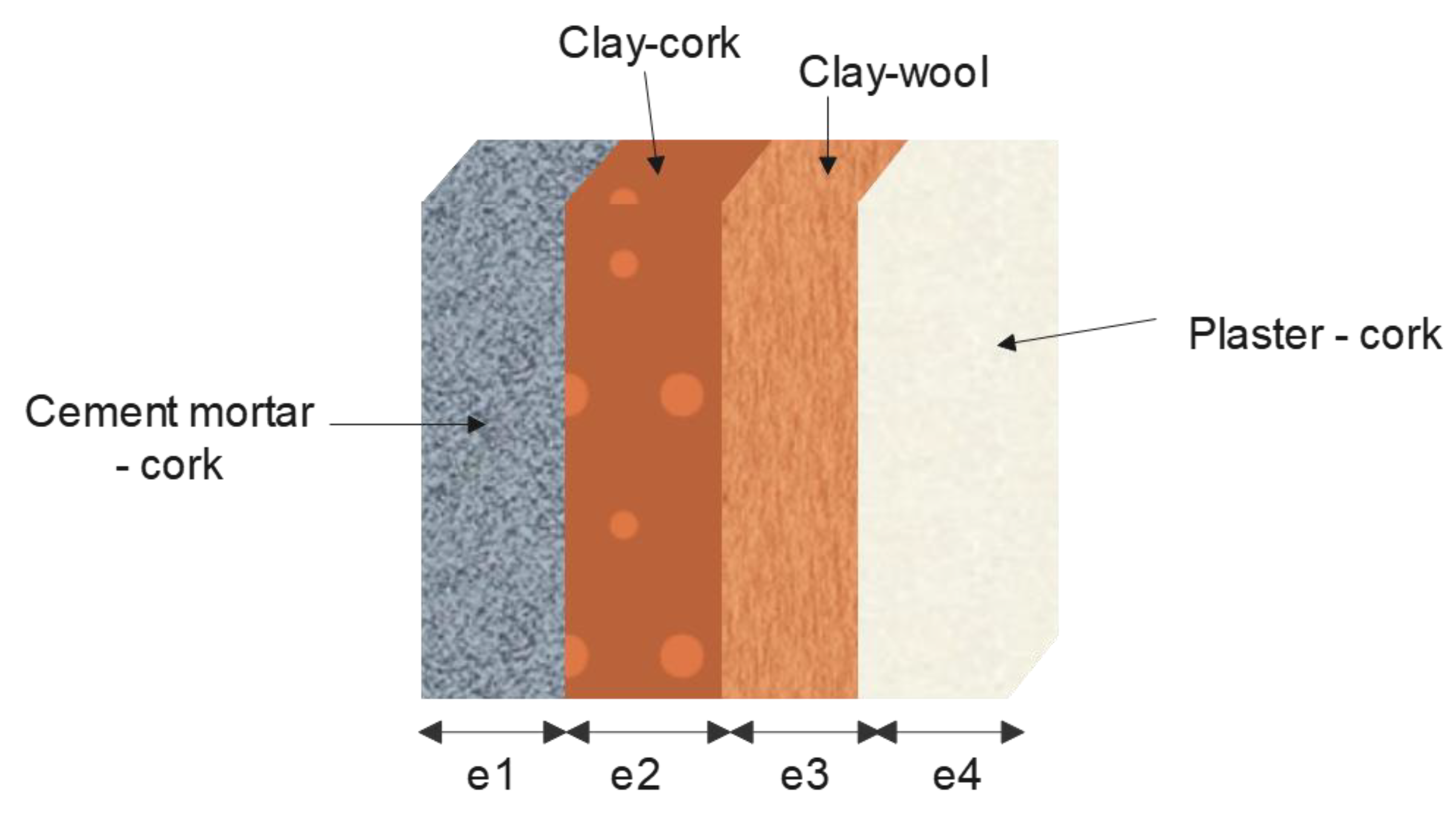
2.1.7. The Studied Multilayer Material
The material studied was a multilayer material composed of four layers as displayed in Figure 1. This multilayer material is presented as a wall; three thicknesses of wall were studied of 0.3 m, 0.4 m, and 0.5 m. The outer layer is composed of the composite cement mortar–cork with a constant thickness of e1 = 0.015 m. The intermediate layer was made from two layers of clay–cork and clay–wool with a total thickness of e2 + e3. For the inner layer, the thickness of the plaster–cork composite was fixed at e4 = 0.015 m, with a cork particle size ranging from 0.0025 m to 0.005 m.
For the intermediate layers, a number of scenarios were studied with varying layer thicknesses. The inner and outer layers stayed constant throughout the study.
Table 2 illustrates an example of the studied cases of the multilayer material for a total wall thickness of 0.3 m. For the wall of 0.4 m and 0.5 m, the authors proceeded in the same way as with the same percentages of the intermediate layer.
2.2. Methods
The Asymmetrical Hot Plate Method
In order to assess the thermal conductivity of the studied multilayer material, the authors opted for the asymmetrical hot plate method in a steady-state regime [11]. The prepared samples (three samples) were tested three times for accurate results.
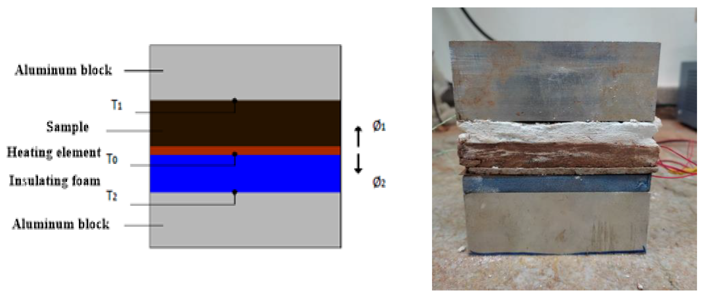
Figure 2 illustrates the experimental setup of the following method. The sample was placed on a heating element (0.1 m × 0.1 m). Below the sample, an insulating foam of polyethylene with a known conductivity of 0.04 W/m2·K and dimensions of 0.1 m × 0.1 m × 0.01 m was situated. The foam was used to ensure that the majority of the heat flux emitted by the resistance passed to the sample.
In order to reach the steady-state regime in a short period of time, two aluminum blocks were positioned on either side of the system, composed of the sample, heating element and the insulating foam. The temperatures of the heating resistance ranged from 10 °C to 40 °C.
Figure 2 displays the picture of the asymmetrical hot plate method in steady state with the studied multilayer material.
Using this configuration, the equation can be written:
- ϕ is the total flux emitted by the resistance (heating element), ϕ1 the heat flux going through the sample, ϕ2 the heat flux passing through the insulating foam.
- λ1 is the thermal conductivity of the sample to characterize; e1 the thickness of the sample.
- λ2 = 0.04 W/m·K and e2 = 0.01 m are, respectively, the thermal conductivity and thickness of the insulating foam.
However, the heating element is an electrical resistance R dissipating a heat flux by Joule effect when the current (I) flows through it under the effect of an electrical voltage (U); therefore:
S is the heat exchange surface between the heating element and the sample.
Combining Equations (1) and (2), it can be deduced:
- A thermocouple was used to measure the temperature T0 at the center of the heated surface of the sample;
- A second one was used to measure the temperature T1 at the center of the unheated surface of the sample;
- The last thermocouple measured T2 of the unheated side of the insulating foam.
3. Results and Discussion
3.1. Apparent Density Results
The apparent density of the samples can be determined from their dimensions and the dry mass.
The results presented in Table 3 show the apparent density of each layer of the studied multilayer wall.
3.2. Thermal Conductivity Results
The results obtained of the thermal conductivity of the four composites obtained using the asymmetrical hot plate method in a steady-state regime are illustrated in Table 4.
3.3. Thermal Transmittance
After establishing the thermal conductivity of the composites cement mortar–cork, clay–cork, clay–wool and plaster–cork, the thermal transmittance of the multilayer material can be calculated (Equation (4)) using the ISO 6949 method [12].
ei and λi are, respectively, the thicknesses and thermal conductivities of the different layers, and [12].
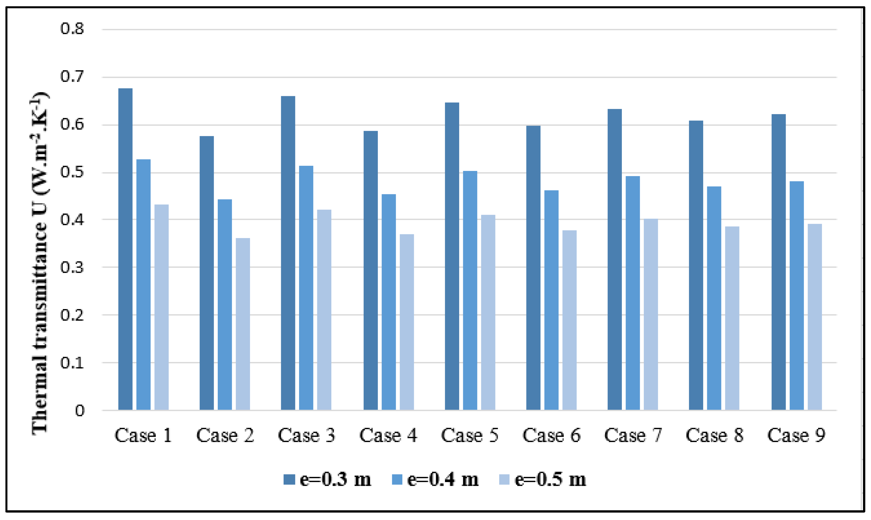
Table 5 regroups the results of the thermal transmittance for the studied multilayer material for the total wall thicknesses of 0.3 m, 0.4 m and 0.5 m. The thicknesses of the middle layers were varied, while the inner and outer layers stayed constant (e1 = 0.015 m, e2 = 0.015 m). For every case study, we calculated the thermal transmittance U in order to assess the best possible scenario with the lowest transmittance.
From the results displayed in Table 5 for the thermal transmittance, the authors observed that the thermal transmittance decreases when the wall thickness increases.
It can be remarked from Figure 3 that all the walls studied the case 2 made from 90% of the composite clay–wool (e3 = 0.423 m) and 10% of the composite clay–cork (e2 = 0.047 m) of the 0.5 m wall show the lowest thermal transmittance U = 0.361 W·m−2·K−1. It can be deduced that the higher percentage we have of the composite clay wool in the multilayer, the lower the thermal transmittance. The clay–wool composite helps to reduce the thermal transmittance of the studied material because it has the lowest thermal conductivity (λ3 = 0.19 W·m−1·K−1) compared to the other used composites in the multilayer.
To emphasize the impact of the studied material on the envelope and thermal loads, we will refer to the work of Mounir et al. [13]. In this paper, the authors investigated the energy efficiency of a multilayer material composed of five distinct materials with different thicknesses (cement–mortar (0.01 m); wool (0.04 m); cork (0.04 m); clay (0.25 m); cement–mortar (0.01 m)). In order to study this material, the authors evaluated the thermal properties of each layer using the hot plate method in a steady-state regime and the flash method. Thermal transmittance and heat loss analyses were also calculated and compared with the building containing concrete and cement mortar (cement–mortar (0.025 m); concrete (0.3 m); cement–mortar (0.025 m)), and a simulation with TRNSYS was conducted. For the thermal transmittance of the concrete wall, the authors found Uconcrete = 2.7 W·m−2·K−1, but for the multilayer material, Umultilayer = 0.4 W·m−2·K−1, which gives us a gain of 85%. With the use of the multilayer material studied in this research, with comparison to the multilayer material developed by Mounir, we can conclude a gain of approximately 10%.
3.4. Simulation Using TRNSYS
A simulation, using the software TRNSYS, of the cooling and heating load over the period of a year was performed on case 2, with the total thickness of the wall of 0.5 m, with a thermal transmittance of U = 0.361 W·m−2·K−1 in a city called Azilal in Morocco, characterized by its severe climate (semi-arid). The modeled house is a simple ground floor with a surface of 100 m2 with three windows: two of them had dimensions of 0.016 m × 0.012 m, the third one 0.021 m × 0.016 m, and a door with dimensions 0.02 m × 0.009 m.
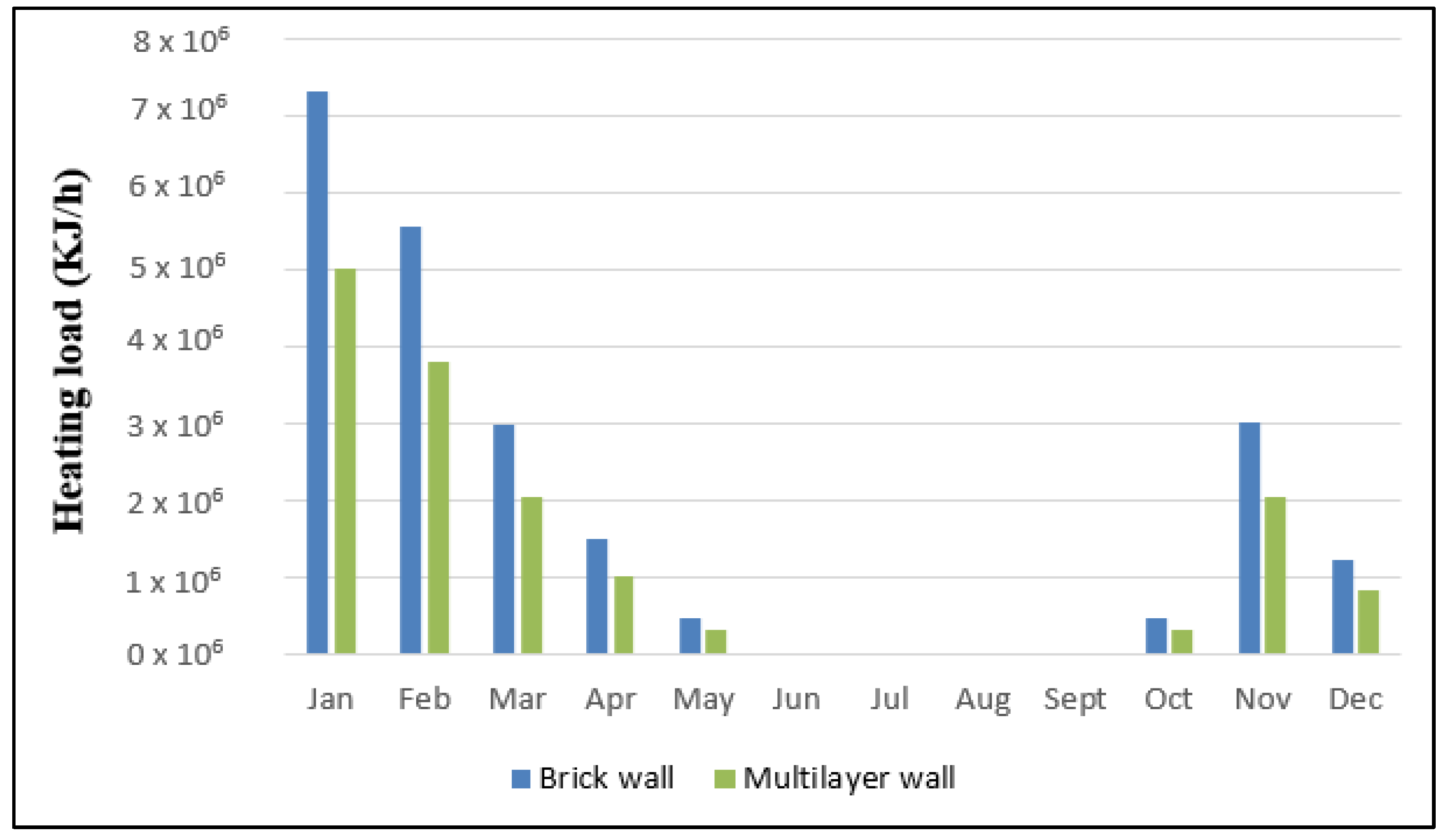
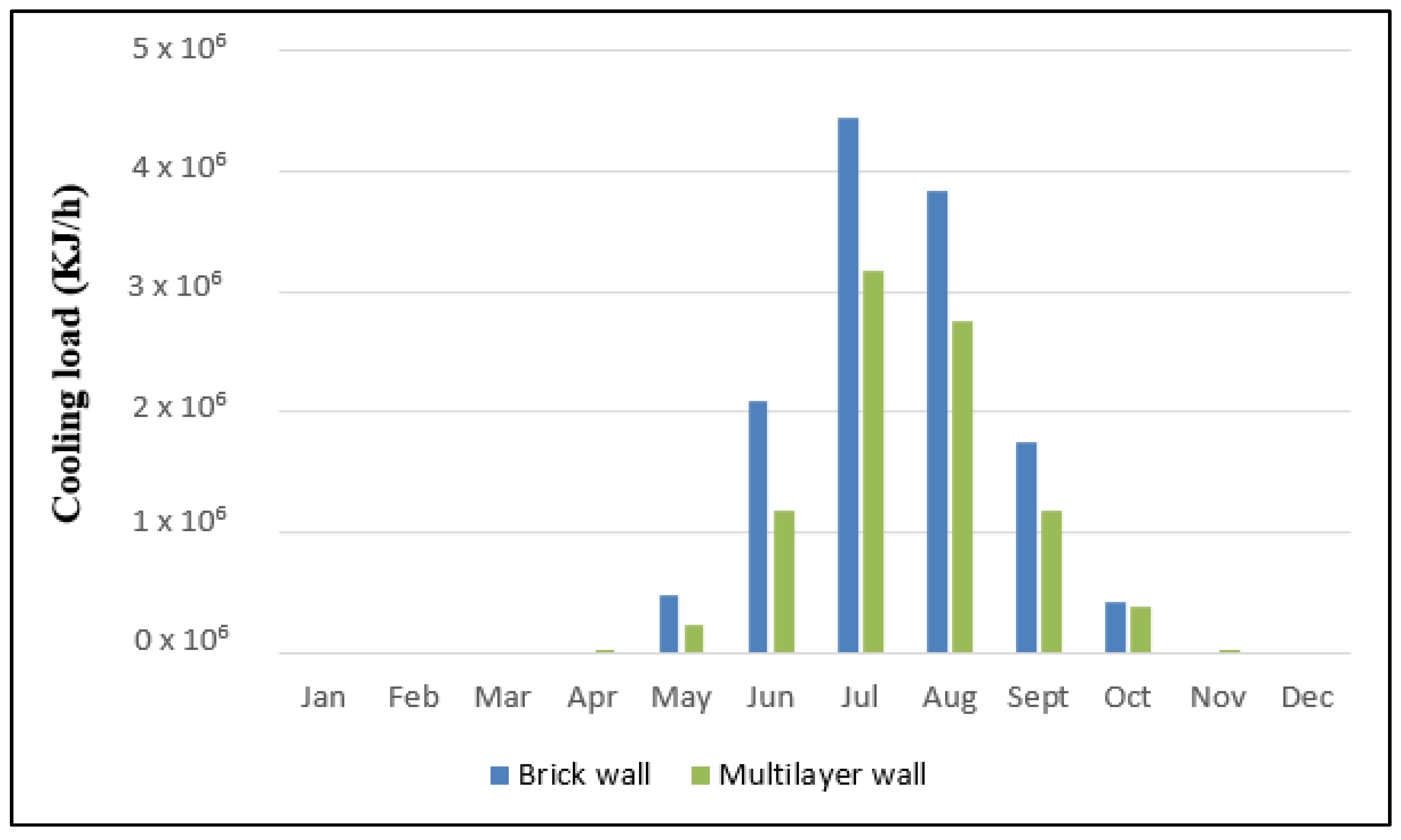
The histograms in Figure 4 and Figure 5 illustrate, respectively, the heating and cooling needs in a building using the new multilayer material. The authors observed that the heating requirements were greater than the cooling needs at the studied site. The total need for heating was 1.55 × 10⁷ KJ·h−1, but for cooling, it was 8.90 × 10⁶ KJ·h−1. This finding can be explained by the fact that the Azilal region in Morocco presents a cold winter, hence the increase in the heating demands [14].
The total yearly energy demand for heating for the following house made from the multilayer material was 4296 KWh. For cooling, the total yearly energy demand was 2472 KWh.
To compare the results found, a building made from conventional bricks was simulated using TRNSYS. The wall was composed of G9 brick with a gypsum board (plasterboard) of 0.0125 m, two layers of insulation of 0.04 m, perforated bricks of 0.37 m and an external coating of 0.04 m. The total yearly energy demand for heating, in the case of the brick wall, was 6281 KWh, and for cooling, was 3615 KWh. We saved 32% of energy by the use of the multilayer wall for both heating and cooling.
Some research was made to assess the energy demand in buildings for different configurations and compositions. For example, El Wardi et al. [15] developed a sandwich material made from clay–granular cork as a core material with a protective coating of plaster and cement mortar. The study simulated three cases with variable external wall solutions. External walls were designed using either clay alone, classic hollow clay brick, or a sandwich material. The results found that the total yearly energy demand for heating and cooling were 2447 kWh for the innovative material brick walls. A value of 4422 kWh was found for clay brick walls and 3535 kWh for hollow clay brick walls. The energy saved using the sandwich material walls was more than 45% and 31% of the energy saved using clay walls and conventional brick walls, respectively.
3.5. Contribution of the Developed Composite to Reducing Energy Systems
In order to assess the electrical energy saved using the designed multilayer material, a study has been conducted of the energy saved when using air conditioning: a split system in the house model. The annual energy for heating was 1.55 × 10⁷ KJ·h−1 for the studied multilayer material, and for the brick, it was 2.26 × 10⁷ KJ·h−1. If we take a split air conditioner with a size of 7 KW (24,000 Btu/h) and 10.5 KW (36,000 Btu/h), for the 7 kW unit, the electrical energy used is 2.21 KW and 3.22 kW for the 10.5 kW unit. The authors calculated the annual energy saved between the model house made from the multilayer material and the one made from the brick wall: the energy saved annually was, respectively, 623 kW and 605 kW for the 7 kW and 10.5 kW units.
The energy efficiency ratio is also used to compare energy use in buildings and is usually expressed in kWh/m2/year, which measures the total energy used in a building for one year in kilowatt hours divided by the gross floor area of the building in square meters [16]. For the studied multilayer material, we found an energy ratio for heating 43 kWh/m2/year and for cooling 24 kWh/m2/year.
To present a perspective of this work’s outcomes, the energy use per unit square area was compared to buildings from various locations and climates. Qawasmeh et al. [17] worked on a building located in Amman (Markka). The apartment’s total area is 110 m2, and it consists of three bedrooms, a kitchen, two baths, a saloon and a living room. The walls of the building were mainly made from concrete and stone. The thermal transmittance of the external walls is U = 0.502 W·m-2·K−1. The annual cooling and heating energy for different configurations of the wall and different rotations range from 114–126 kWh/m2 per year.
The study of Monna et al. [18] analyzes the heating and cooling demand of the An Najah university new campus. The first approach analysis, (Campus energy demand analysis and solar potential) realized with the software CitySim. The total energy demand of campus corresponds to 104 kWh/m2: the average heating demand corresponds to 58 kWh/m2, and the average cooling demand corresponds to 46 kWh/m2.
4. Conclusions
The presented research focused on the characterization of an ecological multilayer material in order to contribute to solutions to combat the environmental challenges that the world faces. The multilayer material was made of four layers. The outer layer was composed of granular cork and cement–mortar; for the inner coating, we used plaster and granular cork. The core layers were made of clay–wool and clay–cork composites. Firstly, the asymmetrical hot plate method was used to assess the thermal conductivity of each layer of our composite. Afterwards, thermal transmittance was calculated with different thicknesses of the intermediate layer and with variant total wall thicknesses of 0.3 m, 0.4 m and 0.5 m. The authors found that thermal transmittance decreases with the increase in the composite clay–wool thickness.
The research was supplemented with a simulation in the software TRNSYS of a model house using our ecological material, using a thermal transmittance of U = 0.361 W·m−2·k−1 in a city with a semi-arid climate. The total yearly energy demand for heating found in the multilayer material was 4296 kWh and cooling was 2472 kWh, with an energy ratio of 67 kWh/m2/year: 43 kWh/m2/year for heating and 24 kWh/m2/year for cooling.
In order to compare the results found, the same model house was simulated using conventional bricks. The total yearly demand in this case study was 6281 kWh for heating and 3615 kWh for cooling. We gained in terms of energy by using the multi-layer wall of 32%.
Author Contributions
Conceptualization, A.K., S.M., S.I.-E. and H.S.; methodology, S.M., A.K., S.I.-E. and H.S.; software, S.I.-E. and S.M.; validation, S.M. and A.K.; formal analysis S.M. and S.I.-E.; investigation, S.I.-E., A.K. and S.M.; resources, S.I.-E.; data curation, S.I.-E.; writing—original draft preparation, S.I.-E.; writing—review and editing, S.M. and A.K.; visualization, S.I.-E., S.M. and A.K.; supervision, S.M.; project administration, A.K. All authors have read and agreed to the published version of the manuscript.
Funding
This research was funded by Centre National center of research and techniques (CNRST), Morocco, grant number 38UM5R2020.
Data Availability Statement
The data presented in this study are available from the corresponding author upon request.
Conflicts of Interest
The authors declare no conflict of interest.
Abbreviations
| Designation | Full Form |
| CM-Co | Cement mortar–cork composite |
| C-Co | Clay–cork composite |
| C-Wo | Clay–wool composite |
| P-Co | Plaster–cork composite |
| ϕ | Heat flux (W·m−2) |
| ϕ1 | heat flux going through the sample |
| ϕ2 | heat flux passing through the insulating foam |
| λ | Thermal conductivity (W·m−1·K−1) |
| φ | Apparent density(Kg·m−3) |
| y | Volume fraction |
References
- Minke, G. Building with Earth: Design and Technology of a Sustainable Architecture; Birkhäuser: Basel, Switzerland, 2013; ISBN 978-3-0346-1262-3. [Google Scholar]
- Mounir, S.; Khabbazi, A.; Khaldoun, A.; Maaloufa, Y.; Elhamdouni, Y. Thermal Inertia and Thermal Properties of the Composite Material Clay-Wool. Sustain. Cities Soc. 2015, 19, 191–199. [Google Scholar] [CrossRef]
- Yang, S.; Wi, S.; Lee, J.; Lee, H.; Kim, S. Biochar-Red Clay Composites for Energy Efficiency as Eco-Friendly Building Materials: Thermal and Mechanical Performance. J. Hazard. Mater. 2019, 373, 844–855. [Google Scholar] [CrossRef] [PubMed]
- Oti, J.E.; Kinuthia, J.M.; Robinson, R.B. The Development of Unfired Clay Building Material Using Brick Dust Waste and Mercia Mudstone Clay. Appl. Clay Sci. 2014, 102, 148–154. [Google Scholar] [CrossRef]
- Charai, M.; Sghiouri, H.; Mezrhab, A.; Karkri, M.; Elhammouti, K.; Nasri, H. Thermal Performance and Characterization of a Sawdust-Clay Composite Material. Procedia Manuf. 2020, 46, 690–697. [Google Scholar] [CrossRef]
- Meng, X.; Yan, B.; Gao, Y.; Wang, J.; Zhang, W.; Long, E. Factors Affecting the in Situ Measurement Accuracy of the Wall Heat Transfer Coefficient Using the Heat Flow Meter Method. Energy Build. 2015, 86, 754–765. [Google Scholar] [CrossRef]
- Del Coz-Díaz, J.J.; Álvarez-Rabanal, F.P.; Alonso-Martínez, M.; Martínez-Martínez, J.E. Thermal Inertia Characterization of Multilayer Lightweight Walls: Numerical Analysis and Experimental Validation. Appl. Sci. 2021, 11, 5008. [Google Scholar] [CrossRef]
- Cooke, G.B. Cork and the Cork Tree-1st Edition. Available online: https://0-www-elsevier-com.brum.beds.ac.uk/books/cork-and-the-cork-tree/cooke/978-1-4832-1319-4 (accessed on 27 March 2022).
- Silva, S.; Sabino, M.; Fernandes, E.; Correlo, V.; Boesel, L.; Reis, R.L. Cork: Properties, Capabilities and Applications. Int. Mater. Rev. 2005, 50, 345–365. [Google Scholar] [CrossRef] [Green Version]
- Zach, J.; Korjenic, A.; Petránek, V.; Hroudová, J.; Bednar, T. Performance Evaluation and Research of Alternative Thermal Insulations Based on Sheep Wool. Energy Build. 2012, 49, 246–253. [Google Scholar] [CrossRef]
- Cherki, A.; Remy, B.; Khabbazi, A.; Jannot, Y.; Baillis, D. Experimental Thermal Properties Characterization of Insulating Cork–Gypsum Composite. Constr. Build. Mater. 2014, 54, 202–209. [Google Scholar] [CrossRef]
- ISO 6946:2017(En), Building Components and Building Elements—Thermal Resistance and Thermal Transmittance—Calculation Methods. Available online: https://www.iso.org/obp/ui/#iso:std:iso:6946:ed-3:v2:en (accessed on 26 December 2021).
- Mounir, S.; Khabbazi, A.; Elwardi, F.Z.; Elharrouni, K.; Maaloufa, Y. Energy Efficiency and Impact Carbon of a Multilayer Material Composed of Ecological Additives. Energy Procedia 2019, 157, 419–427. [Google Scholar] [CrossRef]
- AMEE. Règlement Thermique de Construction au Maroc (RTCM); AMEE: Dundee, Scotland, 2011. [Google Scholar]
- El Wardi, F.Z.; Khabbazi, A.; Cherki, A.-B.; Khaldoun, A. Thermomechanical Study of a Sandwich Material with Ecological Additives. Constr. Build. Mater. 2020, 252, 119093. [Google Scholar] [CrossRef]
- Tahir, M.Z.; Jamaludin, R.; Nasrun, M.; Nawi, M.; Baluch, N.H.; Mohtar, S. Building energy index (bei): A study of government office building in malaysian public university. J. Eng. Sci. Technol. 2017, 12, 192–201. [Google Scholar]
- Qawasmeh, B.R.; Al-Salaymeh, A.; Ma’en, S.S.; Elian, N.; Zahran, N. Energy Rating for Residential Buildings in Amman. Int. J. Therm. Environ. Eng. 2017, 14, 109–118. [Google Scholar] [CrossRef]
- Monna, S.; Coccolo, S.; Kämpf, J.; Mauree, D.; Scartezzini, L. Energy Demand Analysis for Building Envelope Optimization for Hot Climate. In Proceedings of the PLEA 2016—36th International Conference on Passive and Low Energy Architecture, Los Angeles, CA, USA, 11–13 July 2016. [Google Scholar]
Figure 1.
Representation of the studied multilayer material.

Figure 2.
The asymmetrical hot plate method in a steady-state regime.

Figure 3.
Case studies of thermal transmittance of the multilayer material.

Figure 4.
Monthly heating needs for the simulated configurations.

Figure 5.
Monthly cooling needs for the simulated configurations.


Table 1.
Chemical analysis of Bensmim clay using X-ray fluorescence.
| Chemical Component | Percentage of the Component (%) |
|---|---|
| SiO2 | 59.6 |
| Al2O3 | 22.4 |
| Fe2O3 | 6.69 |
| CaO | 0.0777 |
| MgO | 0.97 |
| K2O | 2.53 |
| TiO2 | 0.832 |
| P2O5 | 0.458 |
| P.F | 5.34 |
Table 2.
Case studies of the thicknesses of the multilayer material with a total thickness of 0.3 m.
Table 2.
Case studies of the thicknesses of the multilayer material with a total thickness of 0.3 m.
| Cases | Layer 1 (CM-Co) | Layer 2 (C-Co) | Layer 3 (C-Wo) | Layer 4 (P-Co) |
|---|---|---|---|---|
| Case 1 | 0.015 m | 0.243 m (90%) | 0.027 m (10%) | 0.015 m |
| Case 2 | 0.015 m | 0.027 m (10%) | 0.243 m (90%) | 0.015 m |
| Case 3 | 0.015 m | 0.216 m (80%) | 0.054 m (20%) | 0.015 m |
| Case 4 | 0.015 m | 0.054 m (20%) | 0.216 m (80%) | 0.015 m |
| Case 5 | 0.015 m | 0.189 m (70%) | 0.081 m (30%) | 0.015 m |
| Case 6 | 0.015 m | 0.081 m (30%) | 0.189 m (70%) | 0.015 m |
| Case 7 | 0.015 m | 0.162 m (60%) | 0.108 m (40%) | 0.015 m |
| Case 8 | 0.015 m | 0.108 m (40%) | 0.162 m (60%) | 0.015 m |
| Case 9 | 0.015 m | 0.135 m (50%) | 0.135 m (50%) | 0.015 m |
Table 3.
Results of apparent density of the composites used.
| Sample Series | (Kg·m−3) | |
|---|---|---|
| Cement mortar–cork | 1 | 1160 |
| (y = 0.4) | 2 | 1205 |
| (w/g = 0.5) | 3 | 1189 |
| Ave 1 | 1185 | |
| Clay–cork | 1 | 1114 |
| (y = 0.491) | 2 | 1106 |
| (w/g = 0.25) | 3 | 1108 |
| Ave 1 | 1109 | |
| Clay–wool | 1 | 1779.5 |
| (y = 0.124) | 2 | 1778 |
| (w/g = 0.3) | 3 | 1780 |
| Ave 1 | 1779 | |
| Plaster–cork | 1 | 470.86 |
| (y = 0.509) | 2 | 475.39 |
| (w/g = 0.7) | 3 | 470.17 |
| Ave 1 | 472.14 |
1 Average.
Table 4.
Results of thermal conductivity of the tested samples of the composites.
| Sample Series | λ composite (W·m−1·K−1) | |
|---|---|---|
| Cement mortar–cork | 1 | 0.252 |
| (y = 0.4) | 2 | 0.242 |
| (w/g = 0.5) | 3 | 0.249 |
| Average | 0.25 | |
| Clay–cork | 1 | 0.25 |
| (y = 0.491) | 2 | 0.24 |
| (w/g = 0.25) | 3 | 0.26 |
| Average | 0.250 | |
| Clay–wool | 1 | 0.2 |
| (y = 0.124) | 2 | 0.18 |
| (w/g = 0.3) | 3 | 0.19 |
| Average | 0.19 | |
| Plaster–cork | 1 | 0.125 |
| (y = 0.509) | 2 | 0.125 |
| (w/g = 0.7) | 3 | 0.123 |
| Average | 0.124 |
Table 5.
Results of thermal transmittance of the multilayer material with the different layers.
| The Total Thickness of the Wall | Sample Series | U (W·m−2·K−1) |
|---|---|---|
| e = 0.3 m | Case 1 | 0.675 |
| Case 2 | 0.575 | |
| Case 3 | 0.661 | |
| Case 4 | 0.586 | |
| Case 5 | 0.647 | |
| Case 6 | 0.597 | |
| Case 7 | 0.634 | |
| Case 8 | 0.609 | |
| Case 9 | 0.621 | |
| e = 0.4 m | Case 1 | 0.526 |
| Case 2 | 0.444 | |
| Case 3 | 0.514 | |
| Case 4 | 0.453 | |
| Case 5 | 0.503 | |
| Case 6 | 0.462 | |
| Case 7 | 0.492 | |
| Case 8 | 0.471 | |
| Case 9 | 0.482 | |
| e = 0.5 m | Case 1 | 0.431 |
| Case 2 | 0.361 | |
| Case 3 | 0.421 | |
| Case 4 | 0.369 | |
| Case 5 | 0.411 | |
| Case 6 | 0.377 | |
| Case 7 | 0.402 | |
| Case 8 | 0.385 | |
| Case 9 | 0.393 |
Publisher’s Note: MDPI stays neutral with regard to jurisdictional claims in published maps and institutional affiliations. |
© 2022 by the authors. Licensee MDPI, Basel, Switzerland. This article is an open access article distributed under the terms and conditions of the Creative Commons Attribution (CC BY) license (https://creativecommons.org/licenses/by/4.0/).
Share and Cite
MDPI and ACS Style
Ibn-Elhaj, S.; Mounir, S.; Khabbazi, A.; Sarghini, H. Effect of Clay’s Multilayer Composites Material on the Energy Efficiency of Buildings. J. Compos. Sci. 2022, 6, 151. https://0-doi-org.brum.beds.ac.uk/10.3390/jcs6050151
AMA Style
Ibn-Elhaj S, Mounir S, Khabbazi A, Sarghini H. Effect of Clay’s Multilayer Composites Material on the Energy Efficiency of Buildings. Journal of Composites Science. 2022; 6(5):151. https://0-doi-org.brum.beds.ac.uk/10.3390/jcs6050151
Chicago/Turabian StyleIbn-Elhaj, Sara, Soumia Mounir, Abdelhamid Khabbazi, and Hind Sarghini. 2022. "Effect of Clay’s Multilayer Composites Material on the Energy Efficiency of Buildings" Journal of Composites Science 6, no. 5: 151. https://0-doi-org.brum.beds.ac.uk/10.3390/jcs6050151