New Compact Wearable Metamaterials Circular Patch Antennas for IoT, Medical and 5G Applications


1
Department of Electrical Engineering, Kinneret College, Kinneret 15132, Israel
2
Department of Electrical Engineering, ORT Braude College, Karmiel 2161002, Israel
Appl. Syst. Innov. 2020, 3(4), 42; https://0-doi-org.brum.beds.ac.uk/10.3390/asi3040042
Submission received: 7 July 2020
/
Revised: 1 October 2020
/
Accepted: 5 October 2020
/
Published: 8 October 2020
(This article belongs to the Special Issue Innovations in Wearable Body Area Networks and IOT Systems for Medical Applications)
Abstract
:The development of compact passive and active wearable circular patch metamaterials antennas for communication, Internet of Things (IoT) and biomedical systems is presented in this paper. Development of compact efficient low-cost wearable antennas are one of the most significant challenges in development of wearable communication, IoT and medical systems. Moreover, the advantage of an integrated compact low-cost feed network is attained by integrating the antenna feed network with the antennas on the same printed board. The efficiency of communication systems may be increased by using efficient passive and active antennas. The system dynamic range may be improved by connecting amplifiers to the printed antenna feed line. Design, design considerations, computed and measured results of wearable circular patch meta-materials antennas with high efficiency for 5G, IoT and biomedical applications are presented in this paper. The circular patch antennas electrical parameters on the human body were analyzed by using commercial full-wave software. The circular patch metamaterial wearable antennas are compact and flexible. The directivity and gain of the antennas with Circular Split-Ring Resonators (CSRR) is higher by 2.5dB to 3dB than the antennas without CSRR. The resonant frequency of the antennas without CSRR is higher by 6% to 9% than the antennas with CSRR. The computed and measured bandwidth of the stacked circular patch wearable antenna with CSRR for IoT and medical applications is around 12%, for S11 lover than −6dB. The gain of the circular patch wearable antenna with CSRR is around 8dBi.
1. Introduction
Small wearable sensors and antennas have been analyzed and presented in several papers and books in the last twenty years, see [1,2,3,4,5]. Patch, printed Slot, PIFA, Loop and other printed antennas are used in 5G communication, Internet of Things (IoT) and biomedical systems [2,3,4,5,6]. Meta material structures may be used to design small antennas with high efficiency for wearable medical and IoT systems, [6,7,8,9,10,11,12,13,14,15,16]. Meta material is a periodic artificial material that gain its electrical properties from the material structure rather than from its components. Periodic split ring resonators (SRRs) and metallic posts structures may be used to design materials with specific dielectric constant and permeability as presented in [7,8,9,10,11,12,13,14,15,16]. For example, artificial materials with negative dielectric permittivity were investigated in [7]. A quasi-analytical and self-consistent model to compute the polarizabilities of split ring resonators (SRR) is given in [8]. An experimental setup is also proposed for measuring the magnetic polarizability of SRR structures. Experimental data are compared with theoretical results by using the proposed model. The design of a compact microstrip patch antenna with a reduced size by using metamaterials technologies was presented in [11]. However, in [11] the antenna gain and bandwidth are the same as a standard patch antenna. A wideband transmission-line metamaterial antenna is developed in [12]. The antenna has two transmission line arms that resonate at two different frequencies. Each arm is a microstrip line loaded with five spiral inductors. The antenna radiation efficiency is 65.8% at 3.3 GHz. The antenna has 3% bandwidth. The antenna directivity is around 2.6dBi. The measured peak gain is around 0.79dBi. Small printed antennas such as printed dipole, PIFA and loop antennas have low efficiency [16,17,18,19,20,21,22,23,24,25,26,27,28].
Wearable systems were presented in [2,3,4] and in [29,30,31]. For example, a remote monitoring of patient in hospitals is presented in [29]. An adaptive thermal-aware routing protocol for wireless body area network is presented in [30]. A secure thermal-energy aware routing protocol in wireless body area network is presented in [31]. Active antennas and circular stacked patch antennas were presented in [32,33,34,35,36,37,38,39,40]. One of the main goals of wearable medical systems is to increase disease prevention. By using more wearable medical devices a person can handle and be aware of his private health. Sophistical analysis of continuously measured medical data of large number of medical centers patients may result in a better low-cost medical treatment.
Main Applications of Wearable Medical Systems
- Wearable Medical devices may help to monitor hospital activities;
- Wearable devices may help to operate and monitor home accessories to help diabetes patients, asthma patients, epilepsy patients and assist in solve cardiovascular diseases;
- Wearable devices may help to operate and monitor IoT devices.
Moreover, wearable antennas may be used in IoT devices. The internet of things (IoT) is a system of interrelated computing devices, mechanical and digital machines, personal devices, objects, animals, peoples, healthcare devices and wireless communication devices that are provided with unique identifiers (UIDs) and the ability to transfer data over a network without requiring human to human or human to computer interaction. The internet of things helps people everyday life, work smarter and get complete control over daily services and procedures. IoT provides smart devices to automate homes, companies and health care centers. IoT is essential to business. IoT provides businesses with a real time observation and inspection how their companies’ systems really work. IoT enables companies to automate processes and reduce labor costs. An IoT ecosystem consists of web-enabled smart devices that use embedded processors, sensors and communication hardware to collect, send and act on data they acquire from their environments. IoT devices share the sensor data they collect by connecting to an IoT gateway or other edge device where data is analyzed locally or sent to the cloud to be analyzed.
In this paper, meta-materials are employed to develop circular patch antennas with high efficiency for medical, IoT and 5G communication systems. Detail design of several types of metamaterial antennas with Circular Split-Ring Resonators (CSRRs) was presented by the author in [2,3,4]. Circular patch meta-material antennas were not presented in journals. However, circular patch meta-material antennas have several advantages over regular square and rectangular patches. Such as symmetry, ease to generate circular polarization and propagation mode. The computed and measured bandwidth of the stacked circular patch wearable antenna with SRR for IoT and medical applications is around 12%, for VSWR, Voltage Standing Wave Ratio, better than 3:1. The gain of the stacked circular patch with CSRR is around 8.5dB and with 95% efficiency.
The progress in development of small antennas is presented in Figure 1. Figure 1a presents the gain of several small antennas. Figure 1b presents the bandwidth of several small antennas. The values presented in Figure 1 are based on data and results presented in [1,2,3,4,5,6,7,8,9,10,11,12,13,14,15,16,17,18,19,20,21,22,23,24,25,26,27,28,29,30,31,32,33,34,35,36,37,38,39,40].
2. Compact Circular Microstrip Antenna with Split Ring Resonators
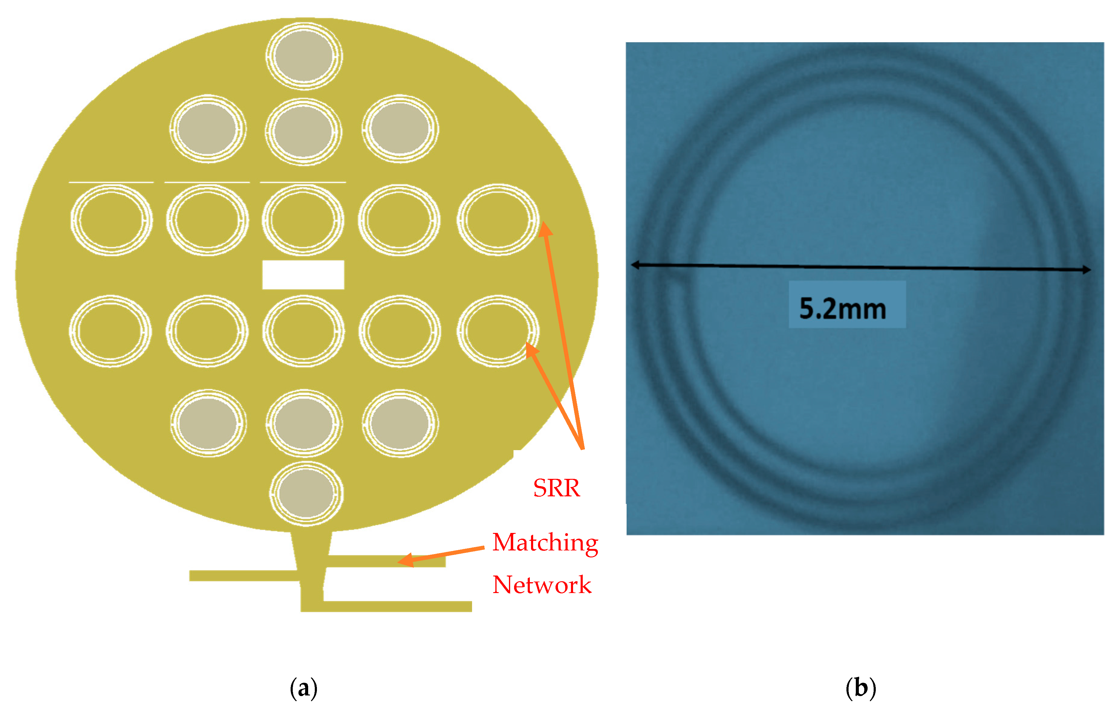
A circular microstrip antenna with CSRRs is presented in this section. The antenna is printed on dielectric substrate with dielectric constant of 2.2, loss tangent of 0.002 and 1.6 mm thick. The radiating element consist of a circular patch with eighteen CSRRs, the maximum number of CSRR that can be inserted in the radiator area. The CSRRs improve the antenna effective area. The diameter of the circular antenna with CSRR, shown in Figure 2a, is 36 mm. The antenna center frequency is 2.6 GHz. The resonant frequency of the dominant mode TM11 of the circular microstrip antenna is given by Equation (1), see [1], where c is the light velocity in vacuum. Where is the radius of the circular microstrip antenna and it can be calculated by using Equation (2), [1]. is the effective dielectric constant. At 2.6GHz the diameter of the circular microstrip antenna should be 46.6 mm. The CSRR outer diameter ring is 5.2 mm, as shown in Figure 2b. The width of the CSRR strip is 0.15 mm. The CSRR dimensions was optimized by using 3D full analysis end commercial electromagnetic software. All the antennas presented in this paper were analyzed by using 3D full wave software, see [41].
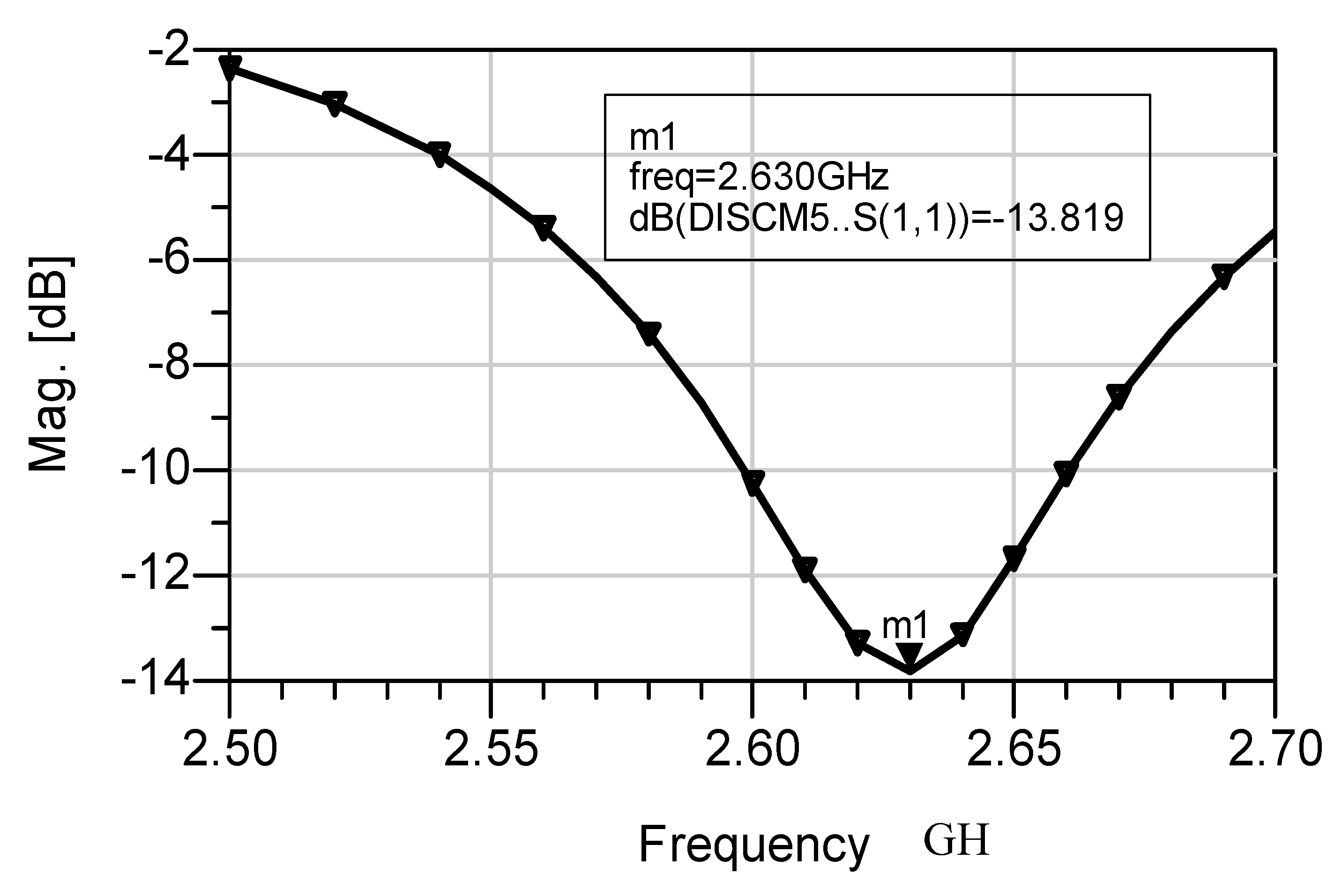
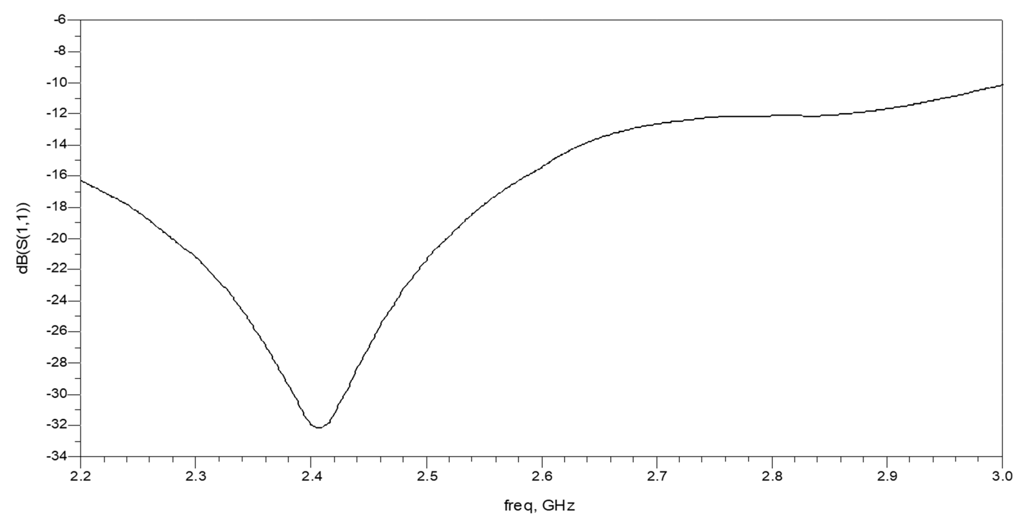
The diameter of the circular antenna with CSRR is smaller by 23% than the diameter of the circular antenna without CSRR. The CSRRs design detail was presented in previous publications, see [2,3,4,5,16]. The CSRRs improve the effective area of the antenna. The maximum number of CSRRs is placed on the circular patch antenna. The circular antenna bandwidth is around 5% for S11 lower than −9 dB. The antenna bandwidth is around 8% for S11 lower than −6 dB as presented in Figure 3. The antenna beam width is around 82°. The antenna gain is around 7.6 dBi as presented in Figure 4. The antenna efficiency is around 83%. The gain and directivity of the circular patch antenna with CSRR is higher around to 2.5 dB to 3 dB than the circular patch antenna without CSRR. The antenna bandwidth may be improved by adding a second radiating layer.
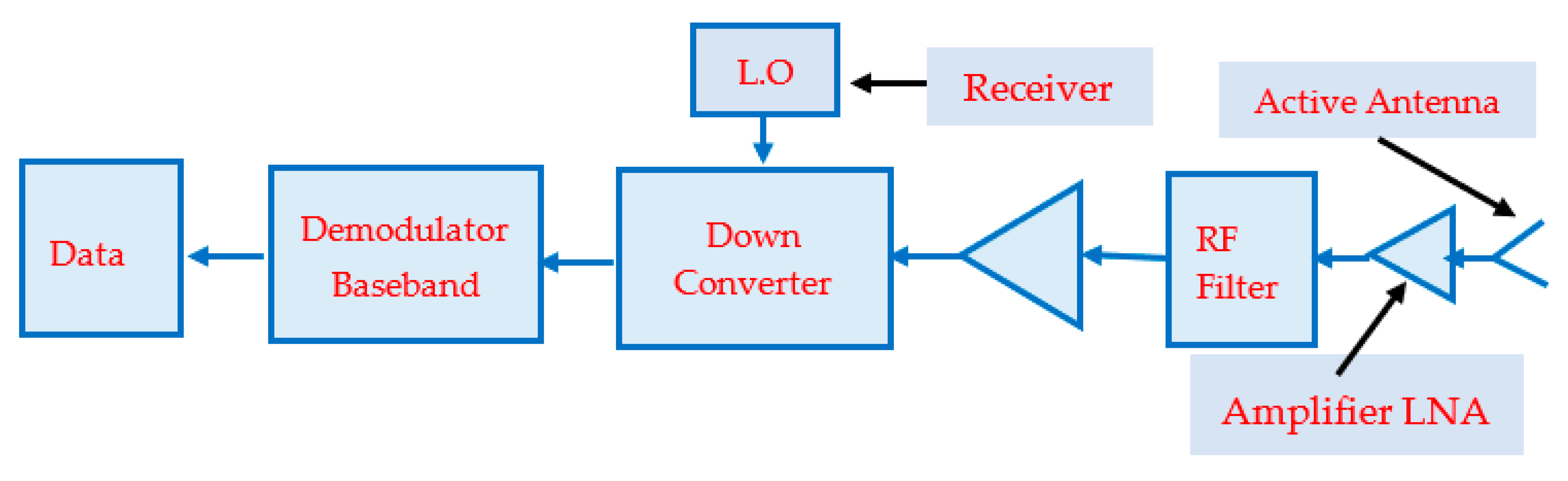
3. Active Receiving Compact Circular Patch Antennas
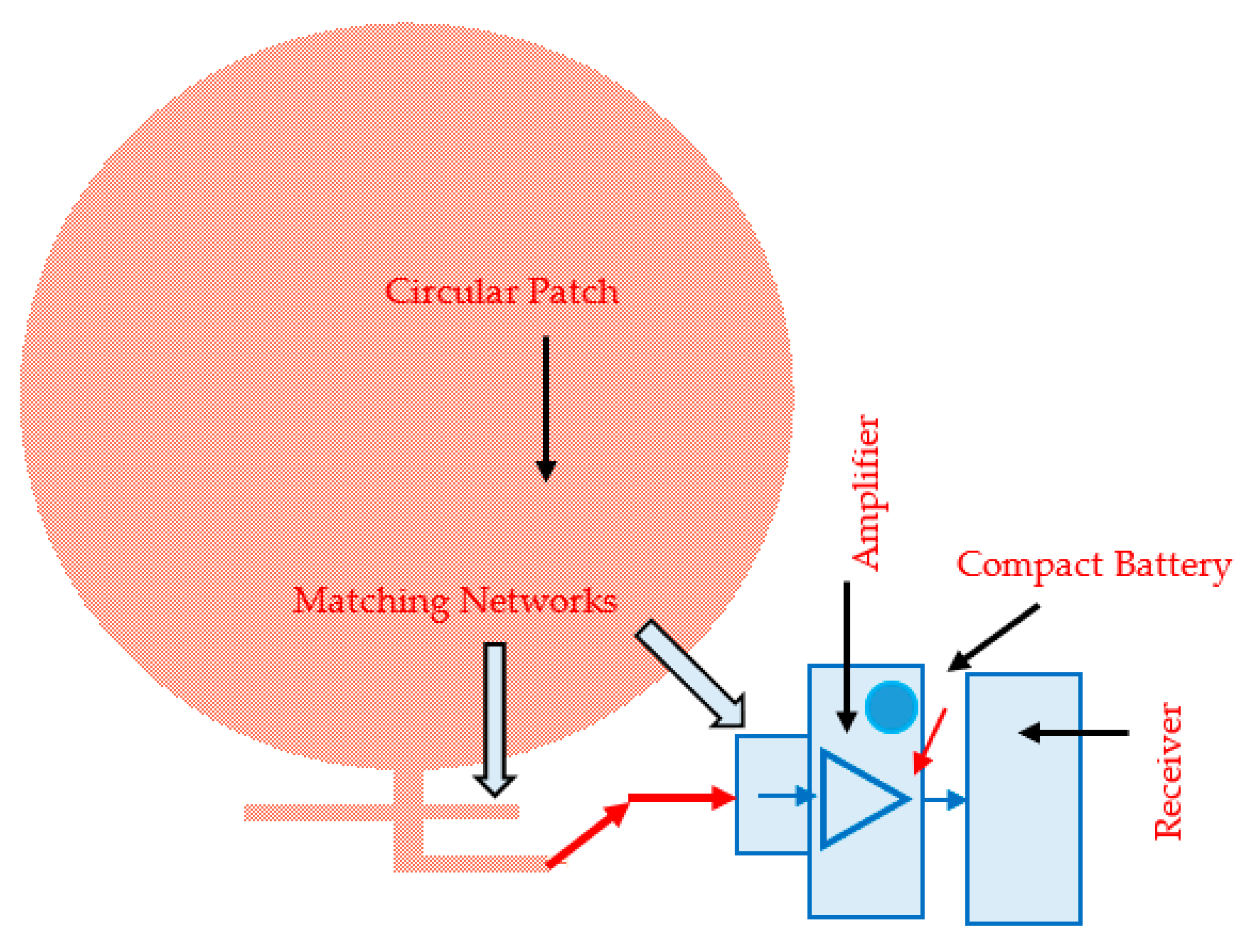
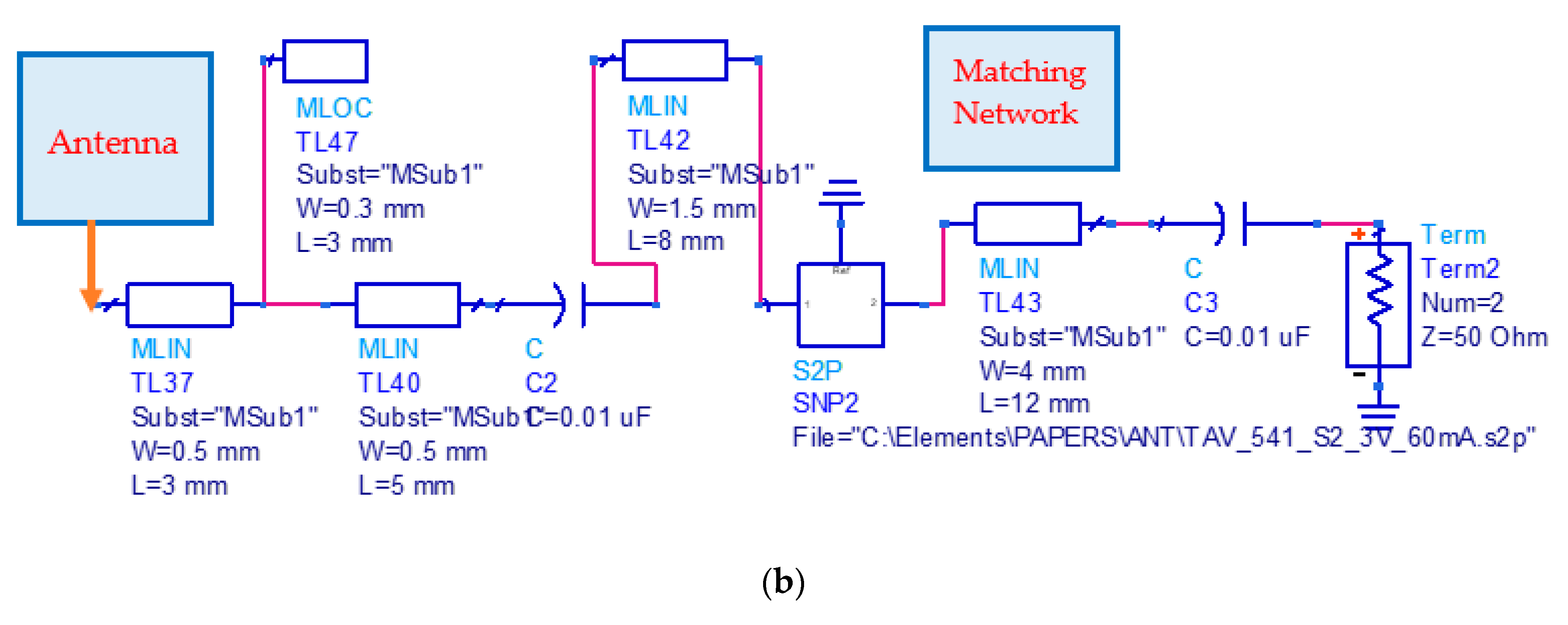
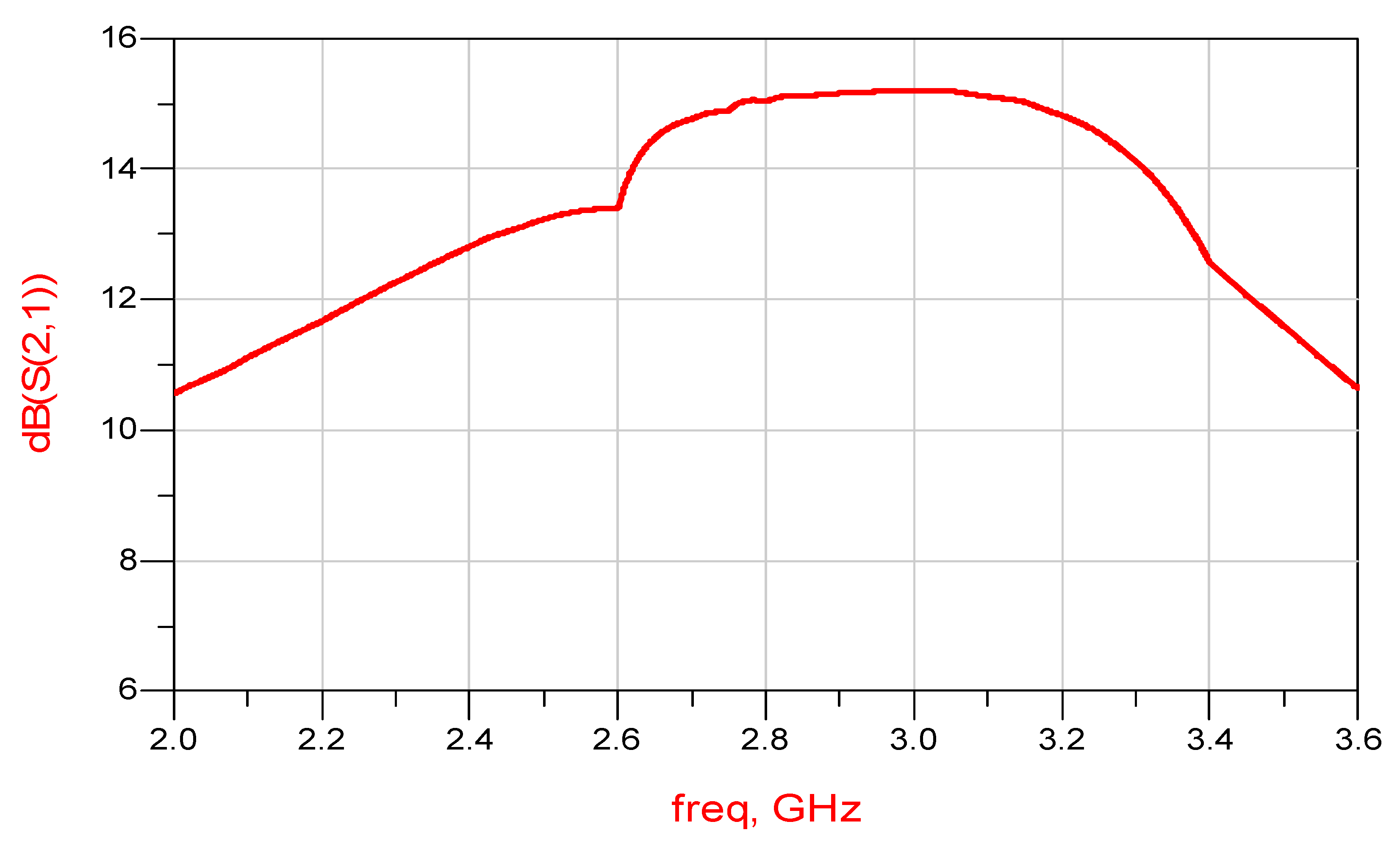
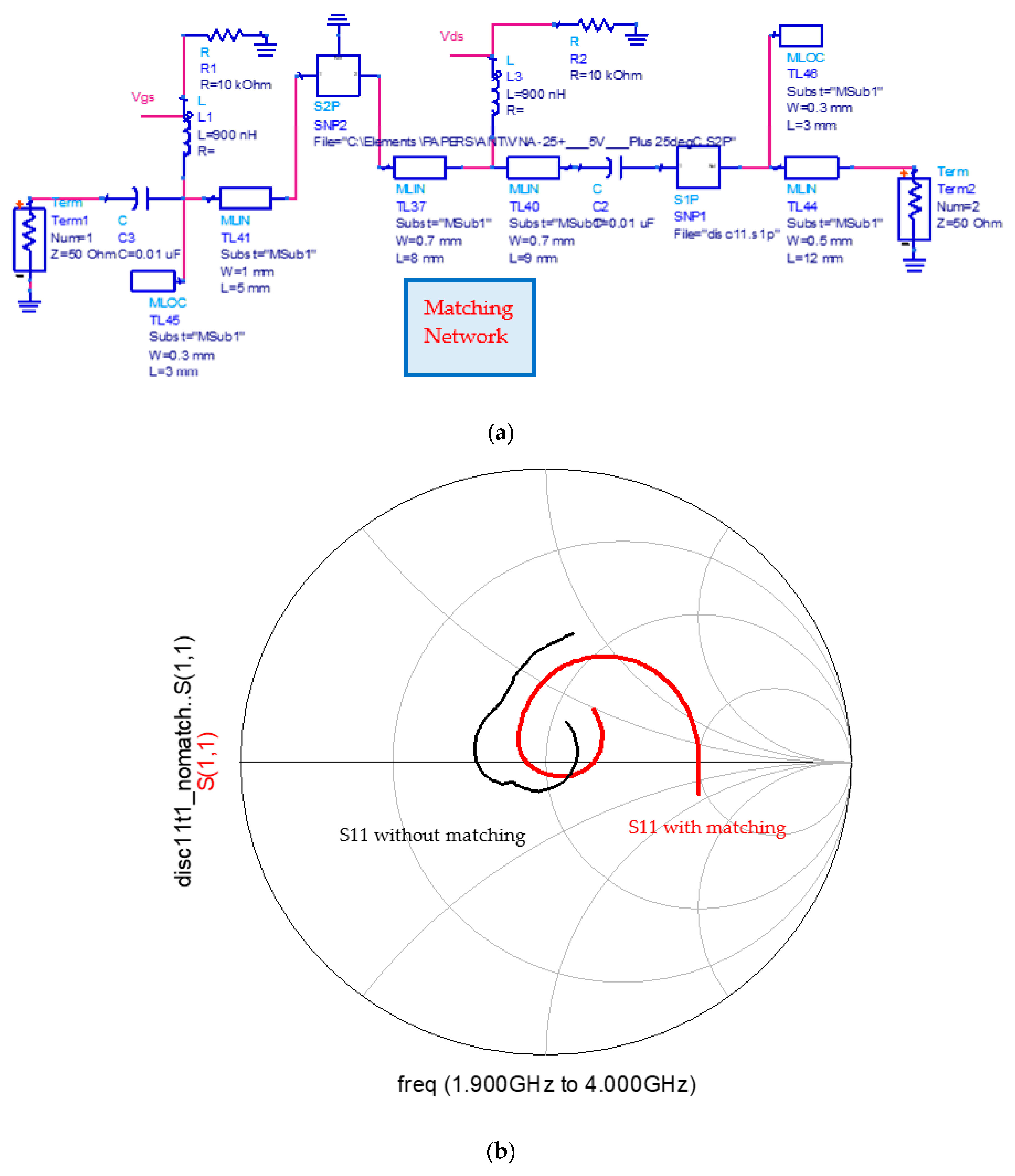
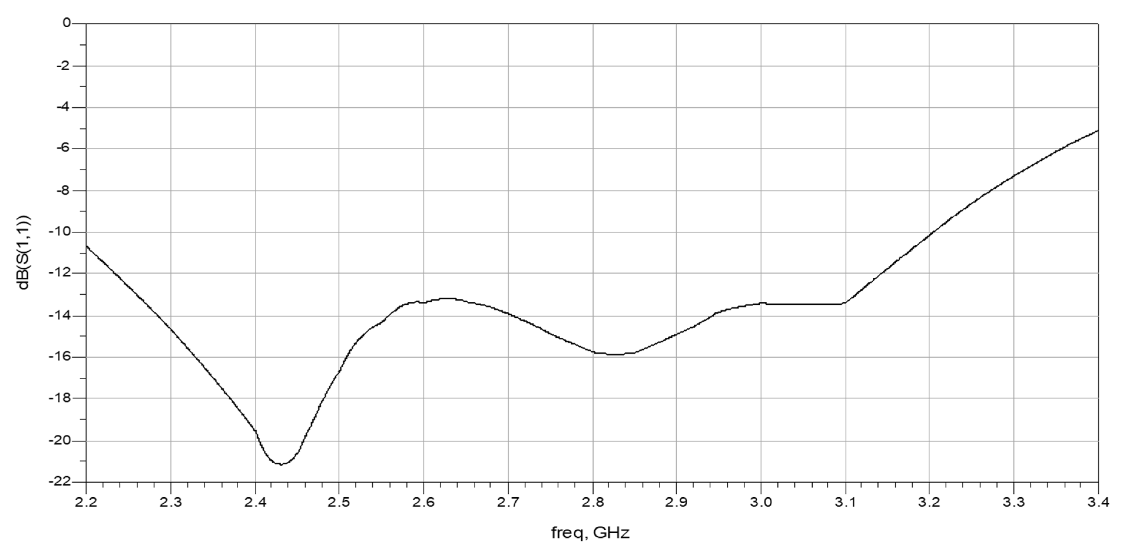
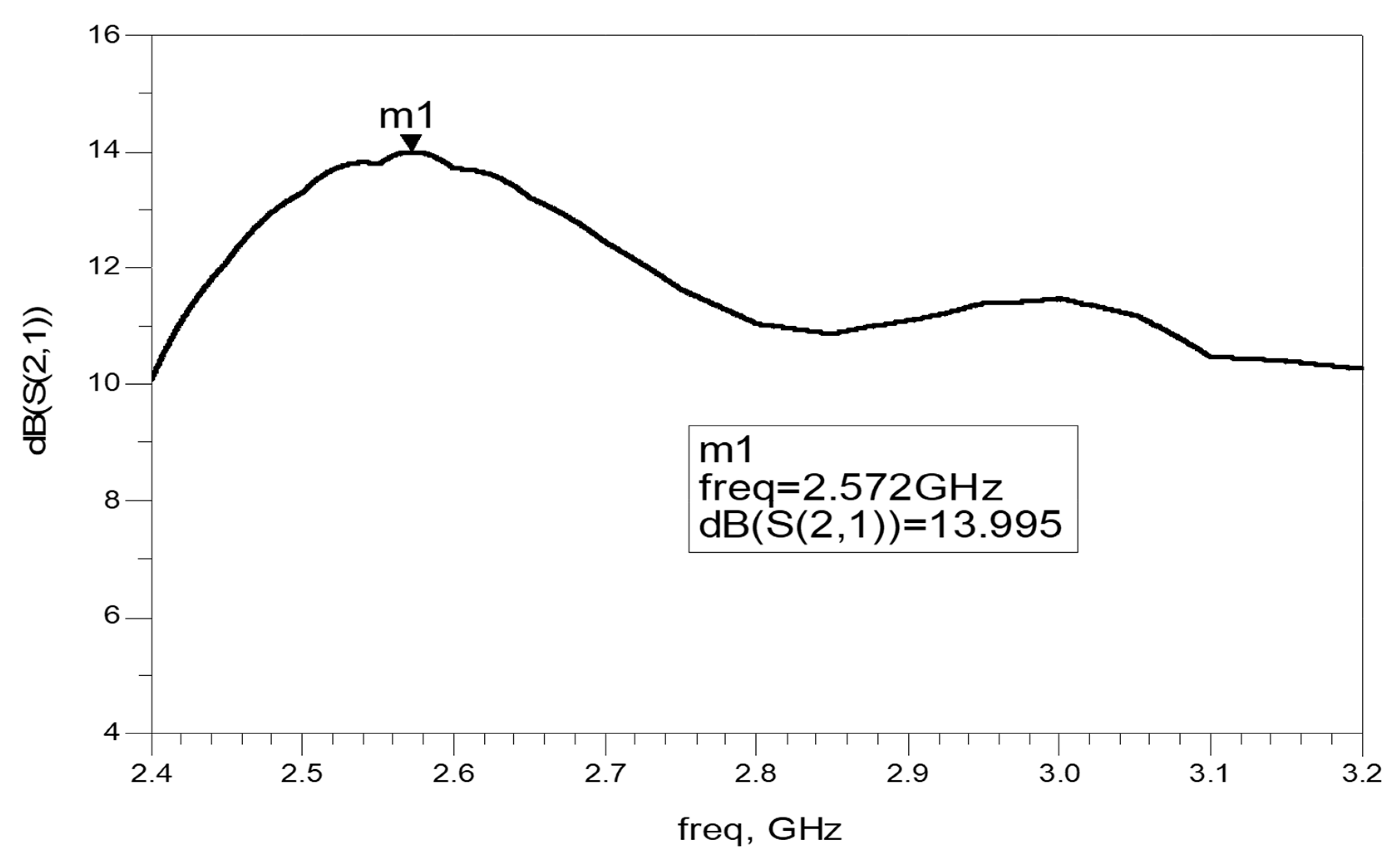
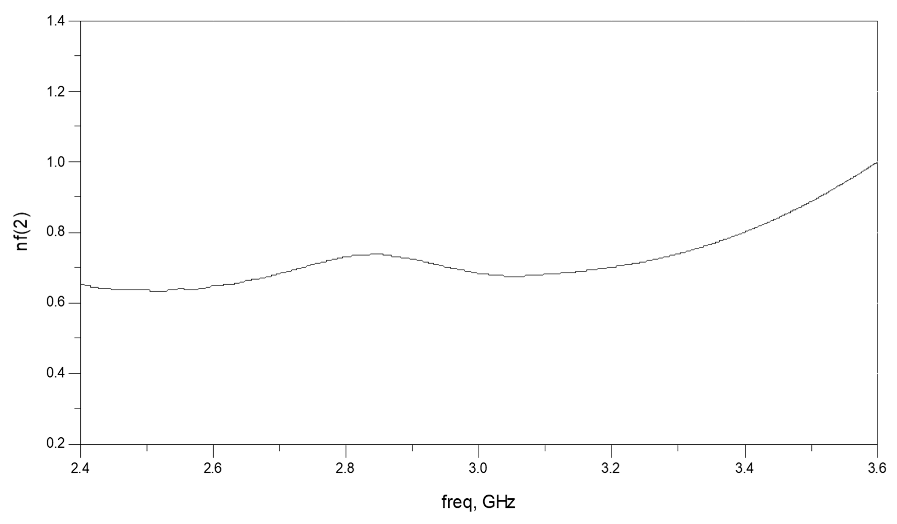
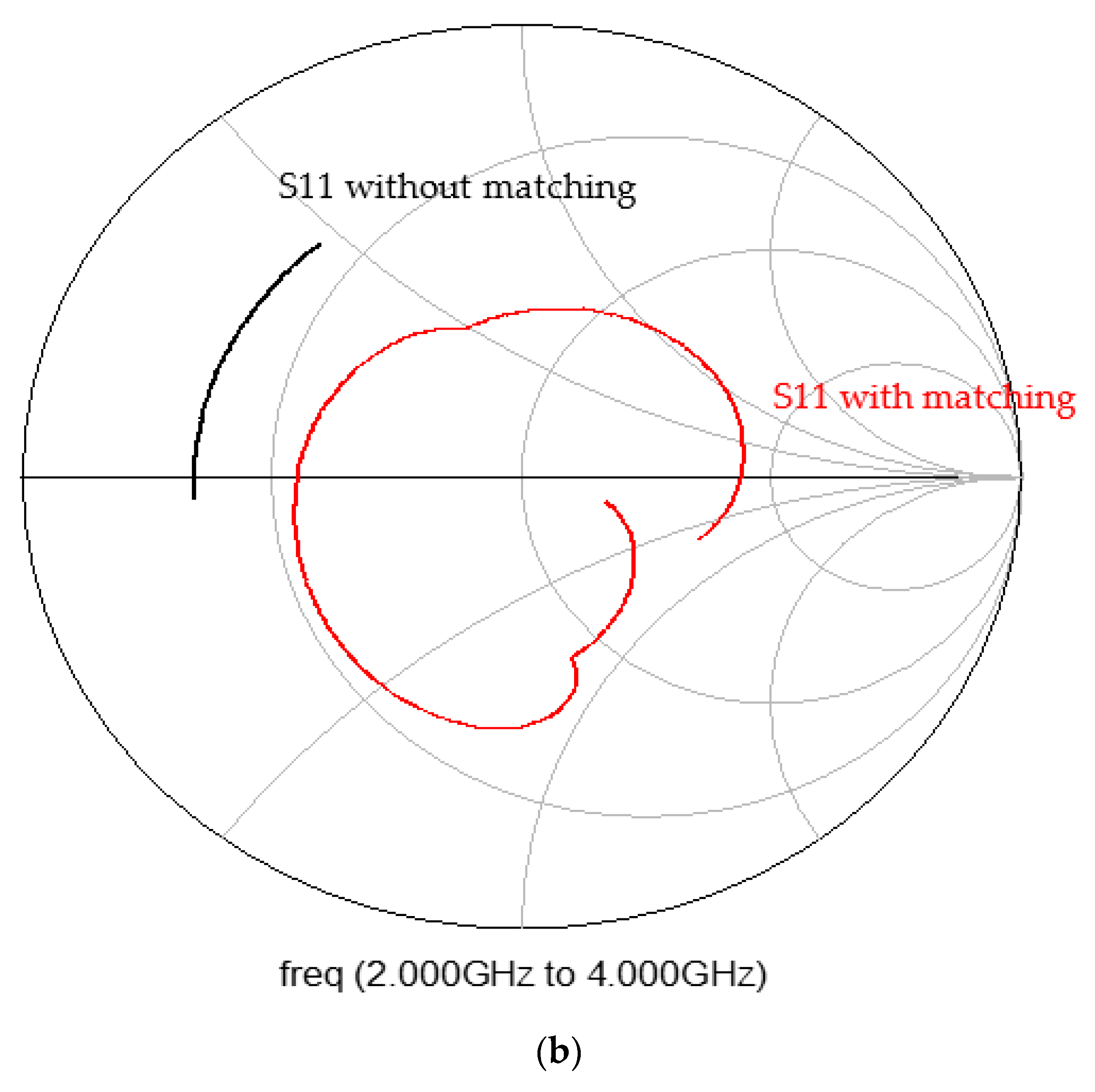
A general receiver block diagram with an active antenna is presented in Figure 5. A Mini-Circuits TAV541 PHEMT LNA, Low noise amplifier, is an integral part of the antenna as presented in Figure 5 and Figure 6. The circular patch is etched on a substrate with a dielectric constant of 2.2 and 1.6 mm thick. The circular patch antenna diameter is 40 mm. The active antenna configuration is shown in Figure 6. An integral input matching network, that is part of the antenna feed network, matches the circular patch to the LNA as shown in Figure 6. An output matching network matches the amplifier output port to the receiver. The dimensions of the input and output matching network are less than 20 × 30 mm and are printed on the same substrate. An integral DC bias network supplies the required voltages to the amplifiers. The amplifier specifications are given in Table 1. The amplifier complex S parameters are listed in Table 2. The amplifier noise parameters are listed in Table 2. The circular patch matched antenna S11 parameter on a human body is presented in Figure 7. The antenna S11 without the matching network is around -4dB in the frequencies from 2.4 GHz to 3.2 GHz. However, S11 of the antenna with the matching network is better than −10 dB in the frequencies from 2.4 GHz to 3.2 GHz. The active antenna bandwidth is around 25% for VSWR better than 2:1. Smith chart diagram of S11 with and without the output matching network is shown in Figure 8a. The antenna matching network was optimized, as shown in Figure 8b. The optimized matching network improved the antenna gain by 1.5 dB. The antenna bandwidth was improved to 44% for VSWR better than 3:1. The active antenna gain on human body is around 15dB at 3GHz and decreases to 11 dB at 3.6 GHz as presented in Figure 9. The antenna noise figure is better than two for frequencies from 2 GHz to 3.6 GHz. Measurement setups of similar antennas were presented in [2]. There is a good agreement between computed and measured results.
4. Active Transmitting Compact Circular Patch Antennas
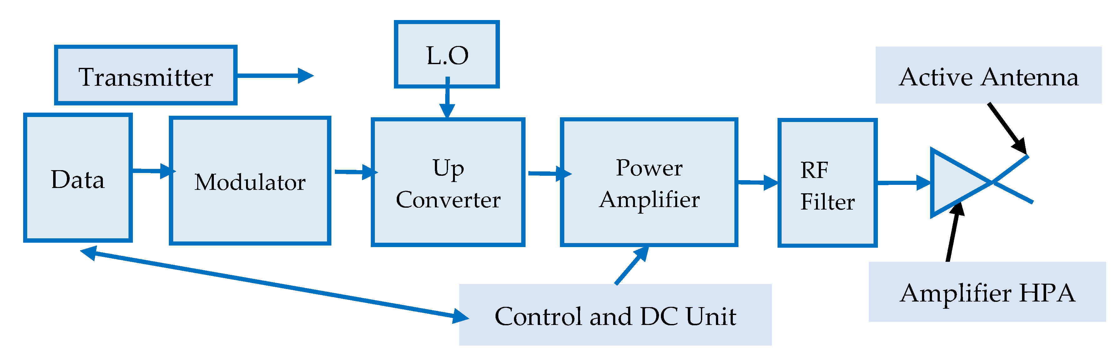
A basic transmitter block diagram with an active antenna is presented in Figure 10. An active circular patch transmitting antenna is presented in Figure 11. The antenna diameter is 40 mm. In Figure 11, the high-power amplifier (HPA) is an integral part of the antenna. The HPA is an MMIC GaAs MESFET, VNA25. The HPA is connected to the transmitting circular patch. The circular patch is matched to the HPA by a matching output network. The HPA input matching network matches the amplifier port to the transmitter.
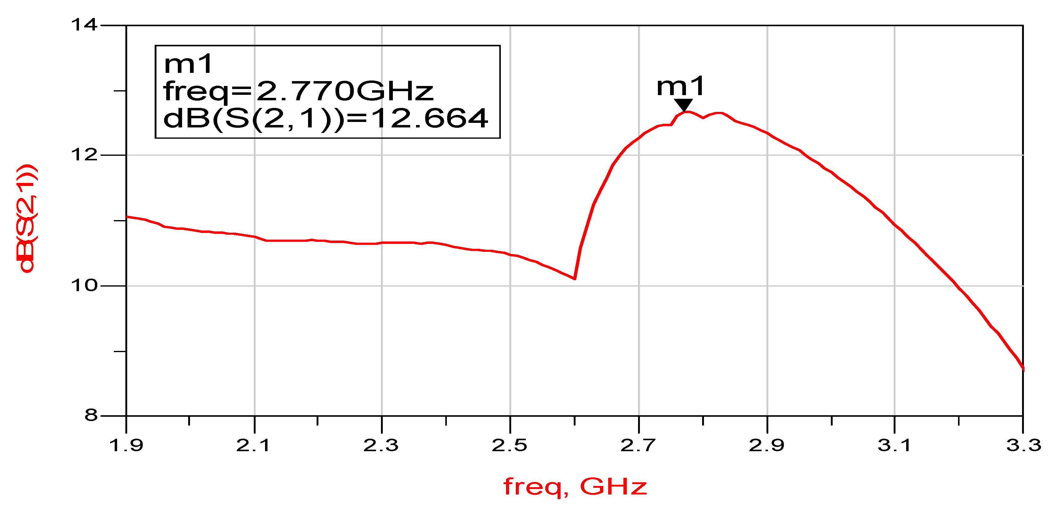
The dimensions of the input and output matching network are less than 22 × 30 mm. The amplifier specifications are listed in Table 3. In Table 4 the HPA complex S parameters are listed. The active transmitting circular patch S11 parameters is better than 2:1 in the frequency range from 2 to 3GHz as presented in Figure 12. The antenna matching network, presented in Figure 13a, was optimized to improve the active antenna bandwidth up to 50% for VSWR better than 3:1. A Smith chart diagram of S11 with and without the output matching network is shown in Figure 13b. The optimized active transmitting antenna S21 parameter, gain on human body, is presented in Figure 14. The active circular patch antenna gain, computed and measured, is 11.0 ± 2dB for frequencies ranging from 1.9 to 3.3 GHz. The active transmitting circular patch antenna output power is around 18 dBm.
5. Active Receiving Compact Double Layer Circular Patch Antennas
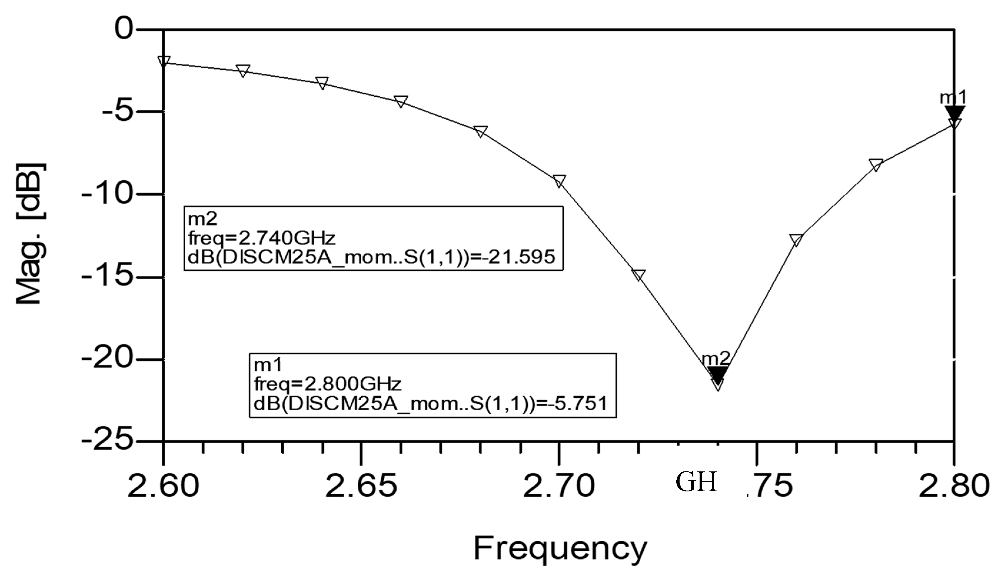
A compact double layer active circular patch antenna is presented in Figure 15. The commercial PHEMT LNA, the same LNA as presented in Section 3, is an integral part of the antenna as presented in Figure 15. The circular patch and the antenna feed network are etched on a substrate with dielectric constant of 2.2 and 1.6 mm thick. The circular resonator diameter is 40 mm. The circular radiator is etched on a substrate with dielectric constant of 2.2 and 1.6 mm thick. The circular radiator diameter is 42 mm. The active antenna configuration is shown in Figure 15. An input matching network matches the antenna to the LNA. An output matching network matches the amplifier output port to the receiver. An integral DC bias network supplies the required voltages to the amplifiers. The circular patch antenna S11 parameter on a human body is presented in Figure 16. The active antenna bandwidth is around 30% for VSWR, which is better than 2:1.
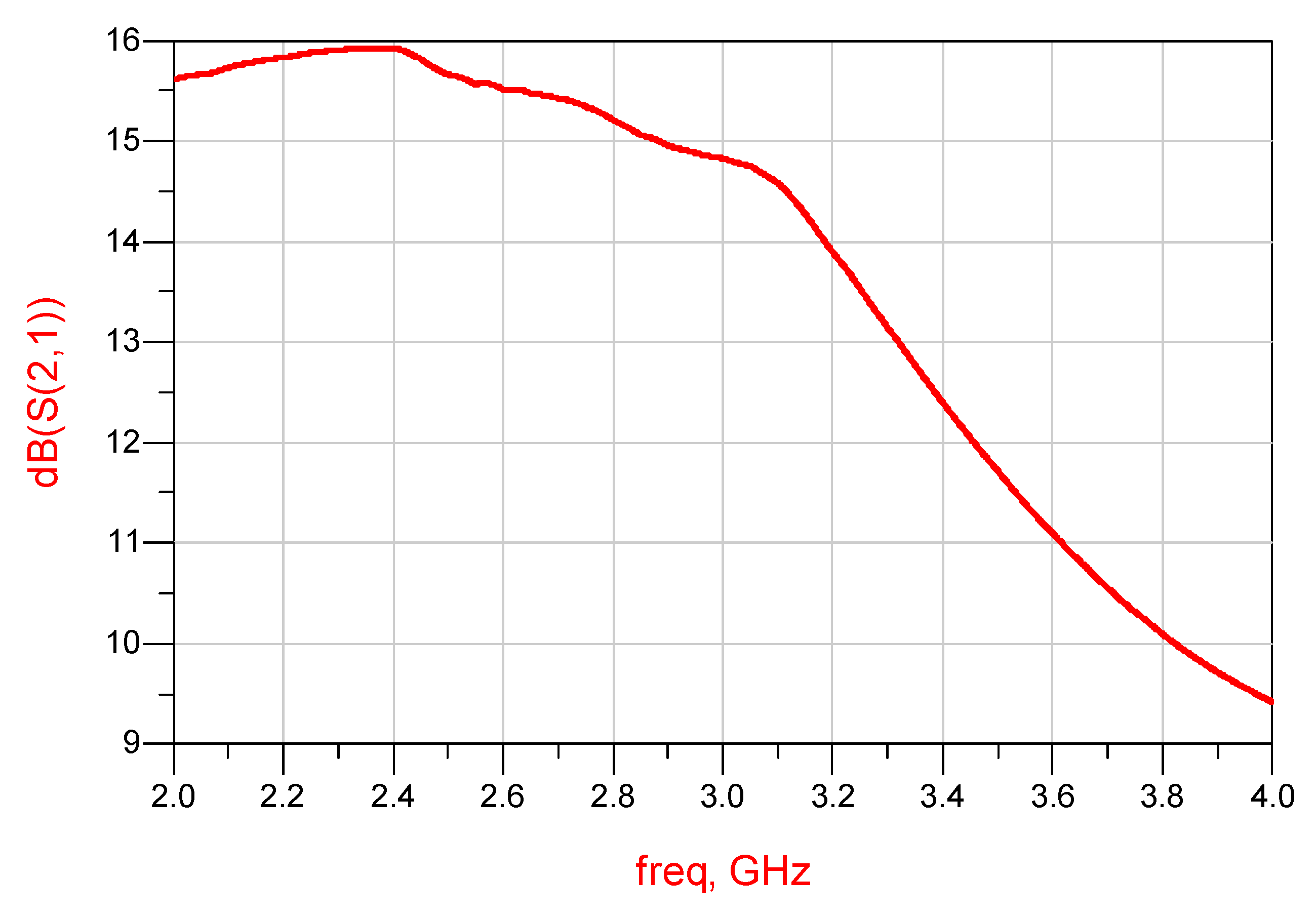
The active antenna gain is around 14 dB at 2.58 GHz and decreases to 10.5 dB at 3.2 GHz. The active antenna S21 parameters, gain on human body, are shown in Figure 17. The active antenna gain is 12 ± 2 dB for frequencies from 2.4 to 3.2 GHz. The active circular patch antenna noise figure is 0.6 ± 0.2 dB for frequencies from 2.4 to 3.4 GHz, see Figure 18. The antenna matching network, presented in Figure 19a, was optimized to improve the active antenna bandwidth up to 70% for VSWR better than 3:1. Smith chart diagram of S11 with and without the output matching network is shown in Figure 19b. The optimized active receiving antenna S21 parameter, gain on human body, is presented in Figure 20. The active circular patch antenna gain is 13.0 ± 3 dB for frequencies ranging from 2 GHz to 4 GHz. There is a good agreement between computed and measured results.
6. Metamaterial Wearable Double Layer Circular Patch Antennas
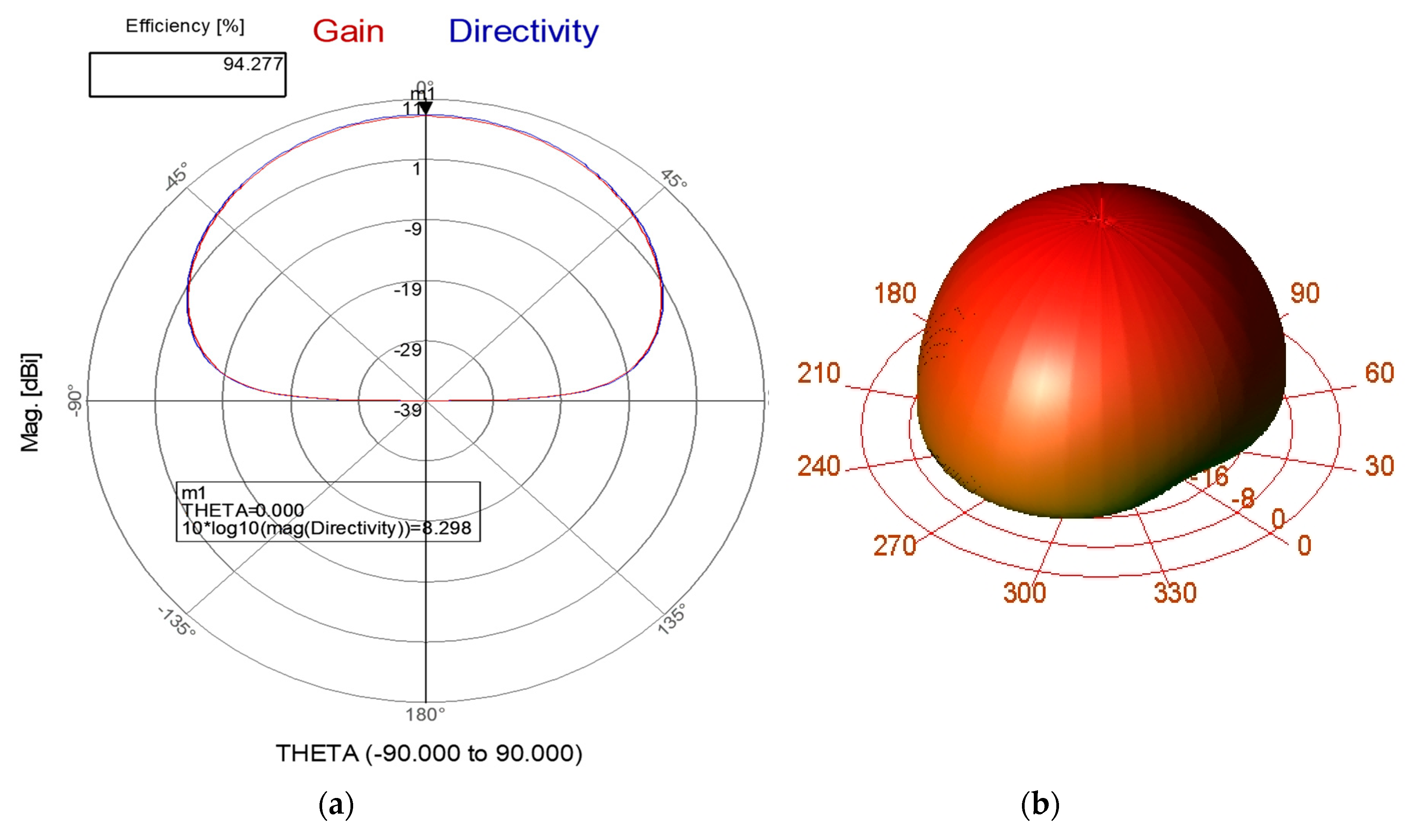
A Metamaterial Wearable Double Layer Circular Patch Antenna is shown in Figure 21. The circular patch and the antenna feed network are etched on a substrate with dielectric constant of 2.2 and 1.6 mm thick, see Figure 21a. The circular resonator diameter is 36.3 mm. The circular radiator is etched on a substrate with a dielectric constant of 2.2 and 1.6 mm thick, see Figure 21b. The circular radiator diameter is 39.3 mm. The radiating element consist of a circular patch with eighteen CSRRs, the maximum number of CSRRs. The Double Layer Circular Patch Antenna is shown in Figure 21c. The spacing between the resonator may be varied from 0 mm to 8 mm to get wider bandwidth from 5% to 10%, The diameter of the circular antenna with CSRR is smaller by 25% than the diameter of the circular antenna without CSRR. The CSRR outer diameter ring is 5.2 mm, see Figure 21d. The width of the CSRR strip is 0.15 mm. The antenna S11 parameter is presented in Figure 22. The antenna beam width is 82°. The antenna gain is around 8.5 dBi as presented in Figure 23a. The antenna efficiency is around 92%. The gain and directivity of the circular patch antenna with CSRR is higher by 2.5 dB than the circular patch antenna without CSRR. The 3D radiation pattern of the Double Layer Circular patch antenna with CSRR is shown in Figure 23b.
7. Wearable Metamaterial Antennas for 5G, IoT and Medical Applications
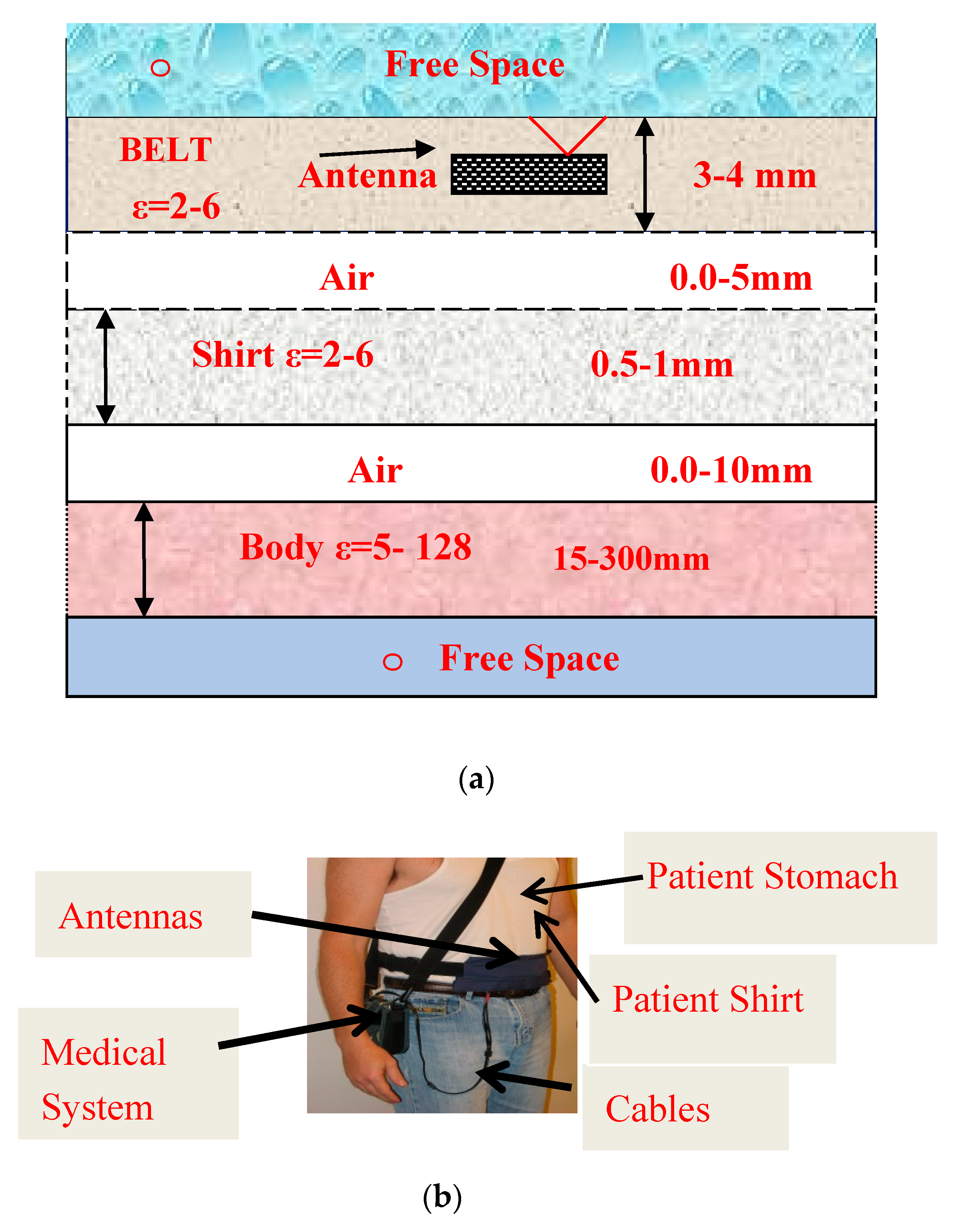
The antennas presented in this paper may be used in 5G, IoT and medical applications. The metamaterial antennas S11 variation near the patient body were computed by using the structure presented in Figure 24a. Several dielectric constant and conductivity of human body tissues are given in Table 5 [16]. The antenna location on the human body is considered by computing S11 for different dielectric constant and conductivity of the body tissues. The dielectric constant of the body tissues varies from 5 at fat tissues to 63 at the colon area, and to 117 at the kidney tissues. The dielectric constant of the body tissue shifts the wearable antenna resonant frequency by 2% to 5%. Wearable antennas may be inserted inside a belt as shown in Figure 24b. The belt thickness and dielectric constant shift the antenna resonant frequency. The belt thickness and dielectric constant was optimized to get the best electrical performance. The antennas impedance and radiation characteristics were computed and measured for air spacing, between the antennas and patient body, of 0 to 10 mm.
A comparison between computed and measured results of antennas with and without CSRR is given in Table 6. The measured results agree with the computed results. Results listed in Table 6 and Table 7 show that the gain of printed antennas with CSRR is 2dB to 3 dB higher than the antennas without CSRR. Wideband passive and active slot antennas, loop and parch antennas were presented in [1]. Printed dipoles with and without CSRR were presented in [2]. A comparison of computed and measured results of compact wearable antennas for medical, 5G and IoT systems is listed in Table 7.
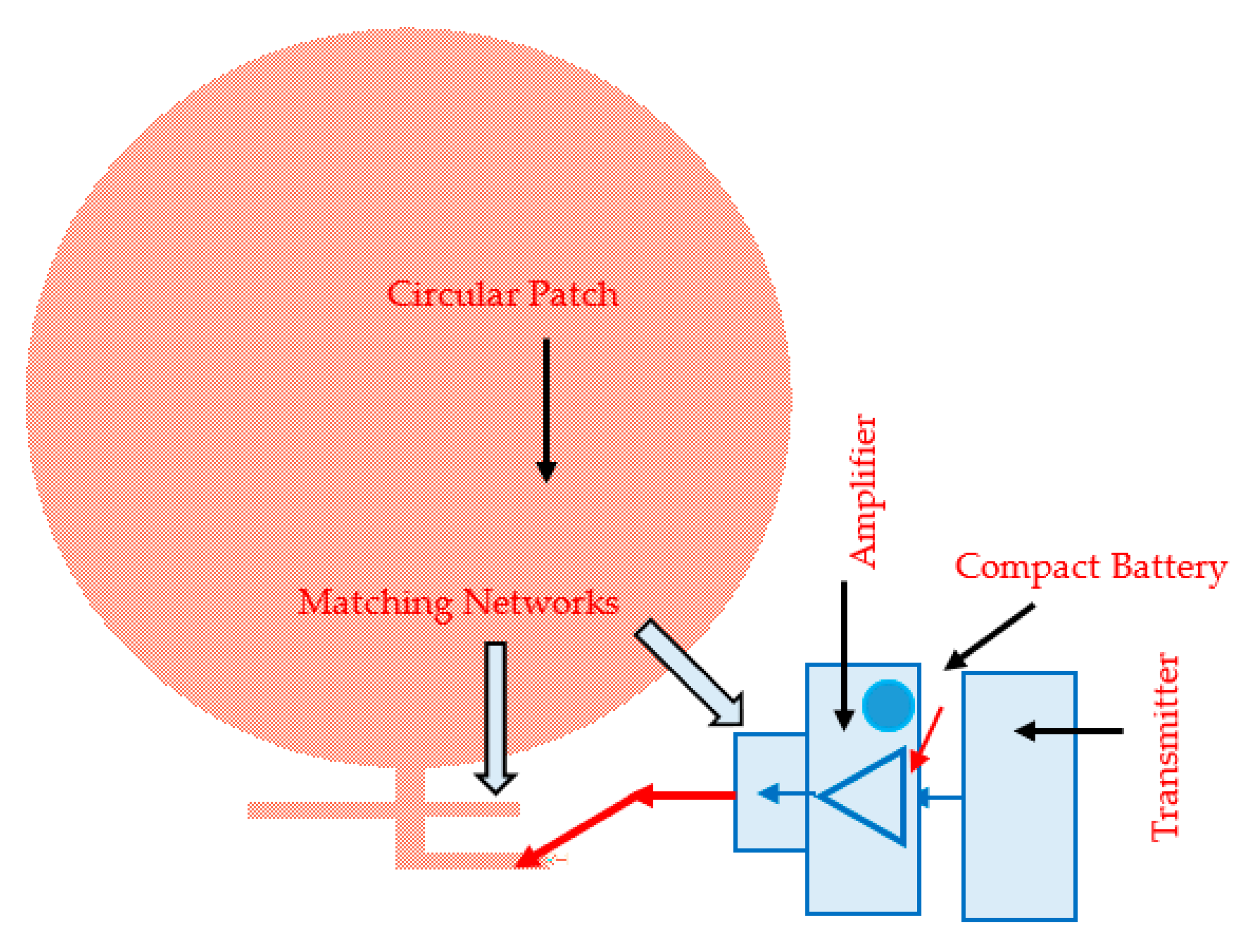
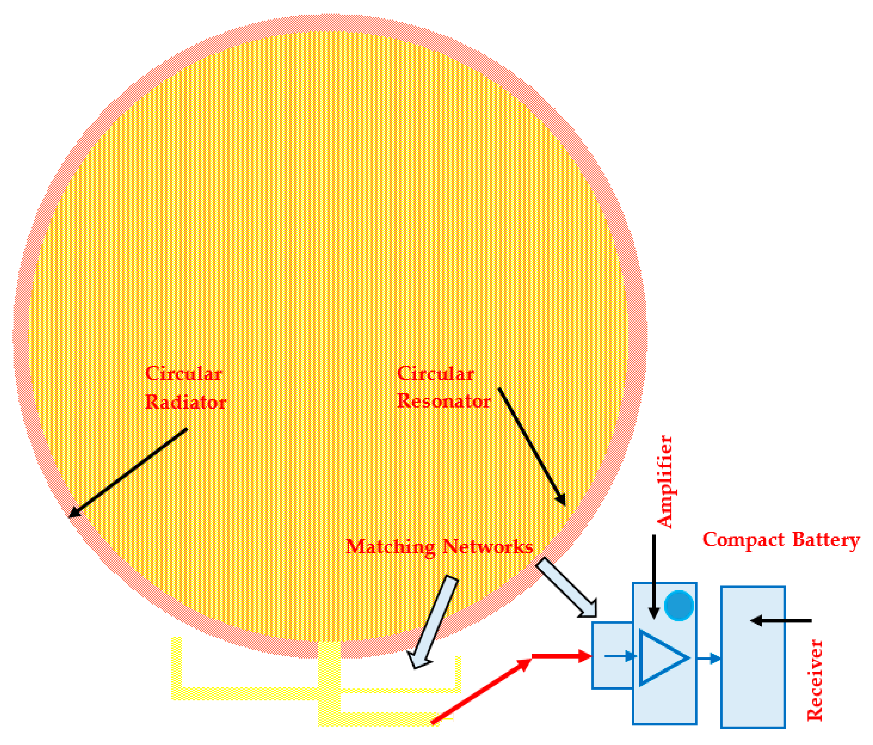
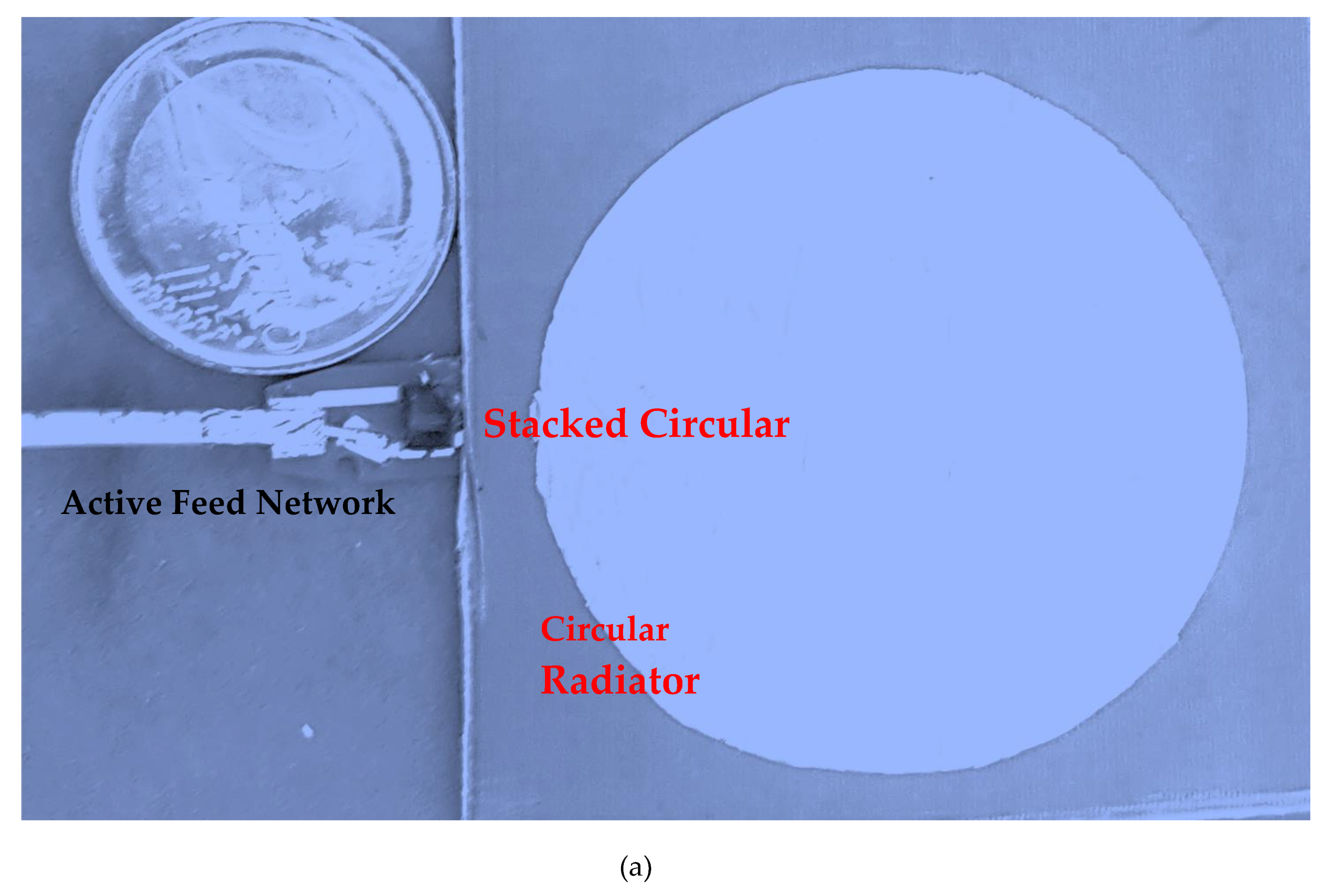
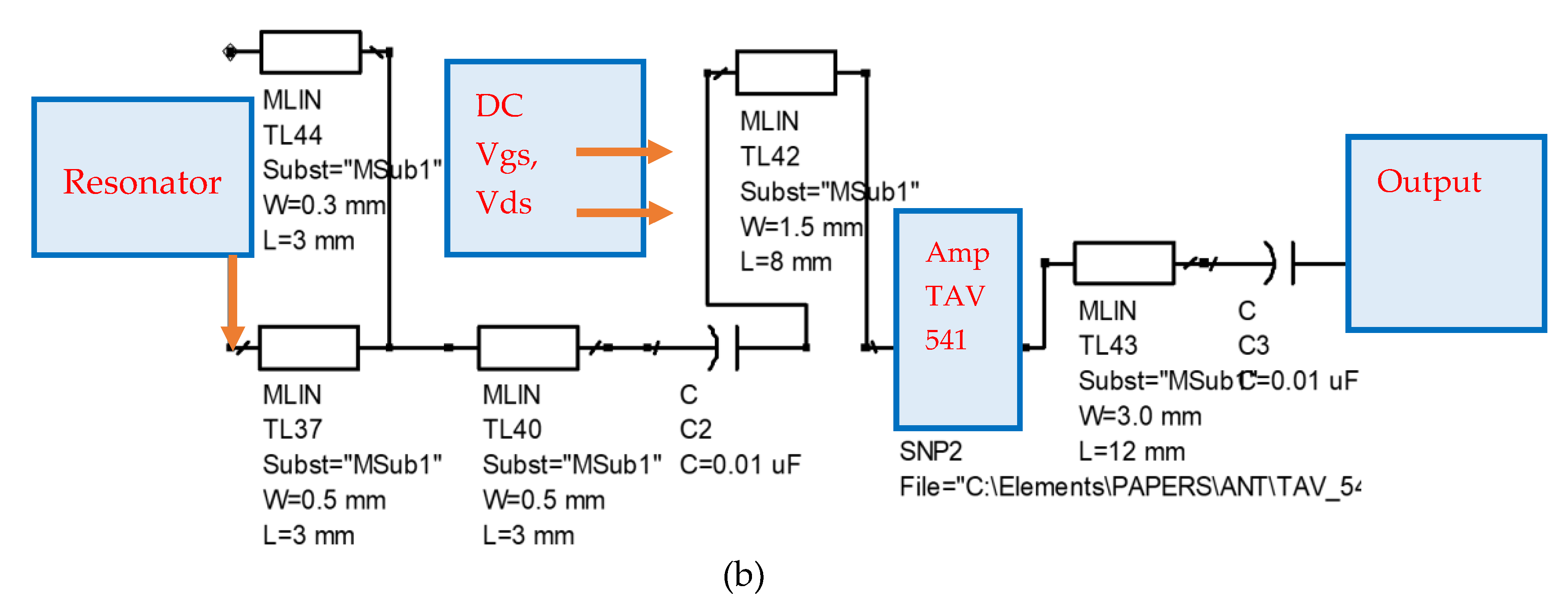
A photo of a prototype of the Active Stacked Circular Patch is shown in Figure 25a. A block diagram and layout of the antenna components are presented in Figure 25b. Global medical monitoring health system with WBAN and BAN Systems is presented in Figure 26. This global medical monitoring health system may be accessed online at any time from every place in the world.
Wearable medical systems and sensors can measure body temperature, heartbeat, blood pressure, sweat rate, perform gait analysis and other physiological parameters of the person wearing the medical device. Gait analysis is a useful tool both in clinical practice and biomechanical research. Gait analysis using wearable sensors provides quantitative and repeatable results over extended time periods with low cost and good portability, showing better prospects and making great progress in recent years. In sport and commercial wearable sensors are used in several applications of gait analysis.
8. Conclusions
Passive and active circular patch wearable antennas may be used in receiving or transmitting WBAN, 5G, IoT and medical systems. In transmitters, an HPA power amplifier is connected to the antenna. In receiving channels, a low noise amplifier (LNA) is connected to the antenna.
Wideband passive and active circular patch antennas may be employed in wideband wearable 5G communication systems for commercial and medical applications. Passive and active printed antennas bandwidth, efficiency and gain and noise figure are presented and summarized in this paper. The directivity and gain of the antennas with split-ring resonators is higher by 2.5 to 3dB than the antennas without CSRR. The resonant frequency of the antennas without CSRR is higher by 6% to 9% than the antennas with CSRR.
The active and passive antennas presented in this paper are compact, low-cost, wideband passive and active antennas for receiving and transmitting wearable IoT, medical and 5G communication systems.
Wearable body area networks seem to be a significant option for healthcare organizations, hospitals and patients. Wearable technology provides a convenient service that may improve the long-term health and physiological response of patients. Wearable systems support the development of personal health-care networks with online immediate response to treat and improve patients’ health.
The active transmitting circular patch output power is around 18dBm. A summary and comparison of the electrical characteristics of the wearable antennas with and without CSRRs are presented in this paper.
This paper presents wideband active and passive circular patch antennas with high efficiency for commercial and medical applications. The active circular patch antennas bandwidth is around 25% for a reflection coefficient lower than −10dB. The antenna bandwidth and gain were improved by optimizing the active antenna matching network. The active receiving circular patch antenna gain is around 13.5dB. The wideband active and passive circular patch antennas may be designed as dual polarized and circular polarized antennas.
In future work circular polarized circular patch metamaterial antennas with high efficiency for medical, IoT and 5G communication systems will be presented. Moreover, in future work fractal circular patch antennas, with and without CSRRs, with high efficiency for medical, IoT and 5G communication systems will be presented.
Funding
This research received no external funding.
Conflicts of Interest
The author declares no conflict of interest.
References
- James, J.R.; Hall, P.S.; Wood, C. Microstrip Antenna Theory and Design; Institution of Engineering and Technology (IET): London, UK, 1981. [Google Scholar]
- Sabban, A. Novel Wearable Antennas for Communication and Medical Systems; Taylor & Francis Group: Boca Raton, FL, USA, 2017. [Google Scholar]
- Sabban, A. Low Visibility Antennas for Communication Systems; Taylor & Francis Group: Boca Raton, FL, USA, 2015. [Google Scholar]
- Sabban, A. Wideband RF Technologies and Antennas in Microwave Frequencies; Wiley: Hoboken, NJ, USA, 2016. [Google Scholar]
- Sabban, A. New Wideband Printed Antennas for Medical Applications. IEEE Trans. Antennas Propag. 2013, 61, 84–91. [Google Scholar] [CrossRef]
- Pendry, J.B.; Holden, A.J.; Stewart, W.J.; Youngs, I. Extremely Low Frequency Plasmons in Metallic Mesostructures. Phys. Rev. Lett. 1996, 76, 4773–4776. [Google Scholar] [CrossRef] [PubMed] [Green Version]
- Pendry, J.B.; Holden, A.; Robbins, D.; Stewart, W. Magnetism from conductors and enhanced nonlinear phenomena. IEEE Trans. Microw. Theory Tech. 1999, 47, 2075–2084. [Google Scholar] [CrossRef] [Green Version]
- Marque´s, R.; Mesa, F.; Martel, J.; Medina, F. Comparative analysis of edge and broadside coupled split ring resonators for metamaterial design—Theory and Experiment. IEEE Trans. Antennas Propag. 2003, 51, 2572–2581. [Google Scholar] [CrossRef] [Green Version]
- Marque´s, R.; Baena, J.D.; Martel, J.; Medina, F.; Falcone, F.; Sorolla, M.; Martin, F. Novel small resonant electromagnetic particles for metamaterial and filter design. In Proceedings of the ICEAA’03, Torino, Italy, 8–12 September 2003; pp. 439–442. [Google Scholar]
- Marqués, R.; Martel, J.; Mesa, F.; Medina, F. Left-Handed-Media Simulation and Transmission of EM Waves in Subwavelength Split-Ring-Resonator-Loaded Metallic Waveguides. Phys. Rev. Lett. 2002, 89, 183901. [Google Scholar] [CrossRef]
- Rajab, K.; Mittra, R.; Lanagan, M. Size Reduction of Microstrip Antennas using Metamaterials. In Proceedings of the 2005 IEEE APS Symposium, Washington, DC, USA, 3–8 July 2005. [Google Scholar]
- Zhu, J.; Eleftheriades, G. A Compact Transmission-Line Metamaterial Antenna with Extended Bandwidth. IEEE Antennas Wirel. Propag. Lett. 2008, 8, 295–298. [Google Scholar] [CrossRef]
- Baena, J.D.; Marque´s, R.; Martel, J.; Medina, F. Experimental results on metamaterial simulation using SRR-loaded Waveguides. In Proceedings of the IEEE- AP/S International Symposium on Antennas and Propagation, Columbus, OH, USA, 22–27 June 2003; pp. 106–109. [Google Scholar]
- Marques, R.; Martel, J.; Mesa, F.; Medina, F. A new 2D isotropic left-handed metamaterial design: Theory and experiment. Microw. Opt. Technol. Lett. 2002, 35, 405–408. [Google Scholar] [CrossRef]
- Shelby, R.A.; Smith, D.R.; Nemat-Nasser, S.C.; Schultz, S. Microwave transmission through a two-dimensional, isotropic, left-handed metamaterial. Appl. Phys. Lett. 2001, 78, 489–491. [Google Scholar] [CrossRef] [Green Version]
- Sabban, A. Small Wearable Meta Materials Antennas for Medical Systems. Appl. Comput. Electromagn. Soc. J. 2016, 31, 434–443. [Google Scholar]
- Sabban, A. Wearable Antenna Measurements in Vicinity of Human Body. Wirel. Eng. Technol. 2016, 7, 97–104. [Google Scholar] [CrossRef] [Green Version]
- Sabban, A. Microstrip Antenna Arrays. In Microstrip Antennas; Nasimuddin, N., Ed.; InTech: London, UK, 2011; pp. 361–384. ISBN 978-953-307-247-0. Available online: http://www.intechopen.com/articles/show/title/microstrip-antenna-arrays (accessed on 1 November 2011).
- Sabban, A. Active Compact Wearable Body Area Networks for Wireless Communication, Medical and IoT Applications. Appl. Syst. Innov. 2018, 1, 46. [Google Scholar] [CrossRef] [Green Version]
- Chirwa, L.; Hammond, P.; Roy, S.; Cumming, D.R.S. Electromagnetic radiation from ingested sources in the human intestine between 150 MHz and 1.2 GHz. IEEE Trans. Biomed. Eng. 2003, 50, 484–492. [Google Scholar] [CrossRef] [PubMed]
- Werber, D.; Schwentner, A.; Biebl, E.M. Investigation of RF transmission properties of human tissues. Adv. Radio Sci. 2006, 4, 357–360. [Google Scholar] [CrossRef]
- Gupta, B.; Sankaralingam, S.; Dhar, S. Development of wearable and implantable antennas in the last decade: A review. In Proceedings of the 2010 10th Mediterranean Microwave Symposium, Guzelyurt, Cyprus, 25–27 August 2010; pp. 251–267. [Google Scholar]
- Thalmann, T.; Popovic, Z.; Notaros, B.M.; Mosig, J.R. Investigation and design of a multi-band wearable antenna. In Proceedings of the 3rd European Conference on Antennas and Propagation, EuCAP 2009, Berlin, Germany, 23–27 March 2009; pp. 462–465. [Google Scholar]
- Salonen, P.; Rahmat-Samii, Y.; Kivikoski, M. Wearable antennas in the vicinity of human body. In Proceedings of the IEEE Antennas and Propagation Society Symposium, Monterey, CA, USA, 20–25 June 2004; pp. 467–470. [Google Scholar]
- Kellomäki, T.; Heikkinen, J.; Kivikoski, M. Wearable antennas for FM reception. In Proceedings of the 2006 First European Conference on Antennas and Propagation, Nice, France, 6–10 November 2006; pp. 1–6. [Google Scholar]
- Lee, Y. Antenna Circuit Design for RFID Applications; Microchip (application note 710c); Microchip Technology Inc.: Chandler, AZ, USA, 2003. [Google Scholar]
- Sabban, A. Microstrip Antenna and Antenna Arrays. U.S. Patent US 4,623,893, 18 November 1986. [Google Scholar]
- Wheeler, H.A. Small antennas. IEEE Trans. Antennas Propag. 1975, 23, 462–469. [Google Scholar] [CrossRef]
- Jamil, F.; Ahmad, S.; Iqbal, N.; Kim, D. Towards a Remote Monitoring of Patient Vital Signs Based on IoT-Based Blockchain Integrity Management Platforms in Smart Hospitals. Sensors 2020, 20, 2195. [Google Scholar] [CrossRef] [PubMed] [Green Version]
- Jamil, F.; Iqbal, M.A.; Amin, R.; Kim, D. Adaptive Thermal-Aware Routing Protocol for Wireless Body Area Network. Electronics 2019, 8, 47. [Google Scholar] [CrossRef] [Green Version]
- Shahbazi, Z.; Byun, Y.-C. Towards a Secure Thermal-Energy Aware Routing Protocol in Wireless Body Area Network Based on Blockchain Technology. Sensors 2020, 20, 3604. [Google Scholar] [CrossRef] [PubMed]
- Lin, J.; Itoh, T. Active integrated antennas. IEEE Trans. Microw. Theory Tech. 1994, 42, 2186–2194. [Google Scholar] [CrossRef]
- Mortazwi, A.; Itoh, T.; Harvey, J. Active Antennas and Quasi-Optical Arrays; John Wiley & Sons: New York, NY, USA, 1998. [Google Scholar]
- Jacobsen, S.; Klemetsen, Ø. Improved Detectability in Medical Microwave Radio-Thermometers as Obtained by Active Antennas. IEEE Trans. Biomed. Eng. 2008, 55, 2778–2785. [Google Scholar] [CrossRef]
- Jacobsen, S.; Klemetsen, O. Active antennas in medical microwave radiometry. Electron. Lett. 2007, 43, 606. [Google Scholar] [CrossRef]
- Ellingson, S.W.; Simonetti, J.H.; Patterson, C.D. Design and evaluation of an active antenna for a 29–47 MHz radio telescope array. IEEE Trans. Antennas Propag. 2007, 55, 826–831. [Google Scholar] [CrossRef]
- Segovia-Vargas, D.; Castro-Galan, D.; Munoz, L.E.G.; González-Posadas, V. Broadband Active Receiving Patch with Resistive Equalization. IEEE Trans. Microw. Theory Tech. 2008, 56, 56–64. [Google Scholar] [CrossRef]
- Rizzoli, V.; Costanzo, A.; Spadoni, P. Computer-Aided Design of Ultra-Wideband Active Antennas by Means of a New Figure of Merit. IEEE Microw. Wirel. Components Lett. 2008, 18, 290–292. [Google Scholar] [CrossRef]
- Sabban, A. Dual Polarized Dipole Wearable Antenna. U.S Patent 8203497, 19 June 2012. [Google Scholar]
- Sabban, A. A New Wideband Stacked Microstrip Antenna. In Proceedings of the IEEE Antenna and Propagation Symposium, Houston, TX, USA, 23–26 May 1983. [Google Scholar]
- ADS Momentum Software, Keysightt. Available online: http://www.keysight.com/en/pc-1297113/advanced-design-system-ads?cc=IL&lc=eng (accessed on 3 January 2018).
Figure 1.
Progress in development of small antennas. (a) Small Antennas Gain; (b) Small Antennas bandwidth.
Figure 1.
Progress in development of small antennas. (a) Small Antennas Gain; (b) Small Antennas bandwidth.

Figure 2.
(a) Circular microstrip antenna with Circular Split-Ring Resonators (CSRR); (b) Photo of a single CSRR.
Figure 2.
(a) Circular microstrip antenna with Circular Split-Ring Resonators (CSRR); (b) Photo of a single CSRR.

Figure 3.
S11 of the wearable circular microstrip antenna with CSRR.

Figure 4.
Radiation pattern of the 2.6 GHz circular microstrip antenna with CSRR.

Figure 5.
Receiver block diagram with wearable active antenna.

Figure 6.
Circular Wearable Active Receiving Patch antenna for Medical and 5G Applications.

Figure 7.
S11 of the Circular patch receiving antenna.

Figure 8.
Circular patch active receiving antenna. (a) Smith chart, S11; (b) Matching network.


Figure 9.
S21 of an Active Circular Receiving Patch antenna.

Figure 10.
Transmitter block diagram with an integral wearable active transmitting antenna.

Figure 11.
Active Circular Transmitting Patch antenna for Internet of Things (IoT) and 5G Applications.
Figure 11.
Active Circular Transmitting Patch antenna for Internet of Things (IoT) and 5G Applications.

Figure 12.
S11 of Transmitting Circular Patch antenna.

Figure 13.
Transmitting Circular Patch antenna: (a) Matching network; (b) S11 of the active antenna.
Figure 13.
Transmitting Circular Patch antenna: (a) Matching network; (b) S11 of the active antenna.

Figure 14.
S21 of an Active Transmitting Circular Receiving Patch antenna.

Figure 15.
Active Receiving Compact Double Layer Circular Patch Antennas.

Figure 16.
Double layer active circular patch antenna S11 parameter on a human body.

Figure 17.
S21 parameter on a human body of the Double Layer Active Circular Patch Antenna.

Figure 18.
Noise Figure of the Double Layer Active Circular Patch.

Figure 19.
Receiving Circular Patch antenna: (a) Matching network; (b) S11 of the active antenna.


Figure 20.
S21 of an Active Stacked Circular Receiving Patch antenna.

Figure 21.
Metamaterial Wearable Double Layer Circular Patch Antennas (a) Resonator; (b) Metamaterial Radiator; (c) Metamaterial Wearable Double Layer Circular Patch; (d) CSRRs Photo.
Figure 21.
Metamaterial Wearable Double Layer Circular Patch Antennas (a) Resonator; (b) Metamaterial Radiator; (c) Metamaterial Wearable Double Layer Circular Patch; (d) CSRRs Photo.

Figure 22.
S11 parameter on a human body of the Double Layer Circular Patch Antenna with CSRRs.

Figure 23.
(a) Radiation pattern of the Double Layer Circular microstrip antenna with CSRR at 2.7 GHz. (b) 3D radiation pattern of the Double Layer Circular patch antenna with CSRR.
Figure 23.
(a) Radiation pattern of the Double Layer Circular microstrip antenna with CSRR at 2.7 GHz. (b) 3D radiation pattern of the Double Layer Circular patch antenna with CSRR.

Figure 24.
(a) Wearable Antenna environment; (b) Wearable Medical System.

Figure 25.
(a) A photo of a prototype of the Active Stacked Circular Patch; (b) Antenna layout.


Figure 26.
Global Medical monitoring health system with WBAN and BAN Systems.


Table 1.
Low noise amplifier (LNA) specification at S band.
| Parameter | Specification | Remarks |
|---|---|---|
| Frequency range | 0.4–3 GHz | |
| Gain | 18 dB @2 GHz | Vds = 3 V; Ids = 60 mA |
| N.F | 0.5 dB @2 GHz | |
| P1dB | 19.1 dBm @2 GHz | |
| OIP3 | 33.6 dBm @2 GHz | |
| Max Input power | 17dBm | |
| Vgs | 0.48 V | |
| Vds | 3 V | |
| Ids | 60 mA | |
| Supply voltage | ±5 V | |
| Package | Surface Mount | |
| Operating Temperature | −40 °C–80 °C |
Table 2.
LNA S parameters and noise parameters at the S band.
| F-GHz | S11 | S11° | S21 | S21° | S12 | S12° | S22 | S22° | ||||
|---|---|---|---|---|---|---|---|---|---|---|---|---|
| 1.04 | 0.74 | −126.2 | 12.74 | 100.13 | 0.05 | 33.69 | 0.29 | −94.96 | ||||
| 1.21 | 0.71 | −137.6 | 11.25 | 92.91 | 0.051 | 30.05 | 0.26 | −104 | ||||
| 1.53 | 0.687 | −154.2 | 9.30 | 82.06 | 0.055 | 26.08 | 0.22 | −119 | ||||
| 1.75 | 0.67 | −164.1 | 8.24 | 75.31 | 0.06 | 23.14 | 0.20 | −128.4 | ||||
| 2.02 | 0.67 | −174.6 | 7.30 | 67.82 | 0.06 | 20.88 | 0.18 | −138.8 | ||||
| Noise Parameters | ||||||||||||
| F-GHz | N. FMIN | N11X | N11Y | rn | ||||||||
| 1 | 0.16 | 0.3424 | 52.98 | 0.042 | ||||||||
| 1.9 | 0.30 | 0.368 | 100.93 | 0.03 | ||||||||
| 2 | 0.32 | 0.371 | 106.01 | 0.03 | ||||||||
| 2.4 | 0.39 | 0.383 | 125.79 | 0.03 | ||||||||
| 3 | 0.48 | 0.400 | 153.93 | 0.036 | ||||||||
| 3.9 | 0.63 | 0.430 | −167.3 | 0.06 | ||||||||
| 5 | 0.81 | 0.465 | −125.53 | 0.11 | ||||||||
Table 3.
High-power amplifier (HPA) specification at S band.
| Parameter | Specification | Remarks |
|---|---|---|
| Frequency range | 0.4–2.5 GHz | |
| Gain | 17.8 dB @2 GHz | Vds = 5 V; Ids = 85 mA |
| N.F | 5.5 dB @2 GHz | |
| P1dB | 18.0 dBm @2 GHz | |
| OIP3 | 29 dBm @2 GHz | |
| Max. Input power | 10dBm | |
| Vgs | 0.48 V | |
| Vds | 5 V | |
| Ids | 85 mA | |
| Supply voltage | ±5 V | |
| Package | Surface Mount | |
| Operating Temperature | −40 °C–80 °C |
Table 4.
High-power amplifier S parameters at the S band.
| F-GHz | S11 dB | S11° | S21 dB | S21° | S12 dB | S12° | S22 dB | S22° |
|---|---|---|---|---|---|---|---|---|
| 1.6 | −12.8 | 134.3 | 18.3 | 123.3 | −44.2 | −93.4 | −18.9 | 113.7 |
| 1.8 | −14.3 | 101.2 | 17.9 | 83 | −43 | −86.3 | −22 | 69.5 |
| 2 | −16.5 | 61.8 | 17.3 | 43.5 | −40.4 | 94.6 | −27 | 6.42 |
| 2.16 | −18.5 | 22.1 | 16.8 | 12.9 | −38 | −105.5 | −27.8 | −70.2 |
| 2.4 | −19.4 | −53.9 | 15.7 | −31.8 | −36 | −128 | −22.2 | −147.2 |
| 2.56 | −17.7 | 99.7 | 15 | −60 | −34.6 | −145.6 | −19.3 | −179.4 |
| 2.7 | −15.7 | 131 | 14.3 | −84.3 | −33.8 | −160.3 | −17.5 | 158.1 |
| 2.86 | −13.7 | 159 | 13.5 | −111.1 | −33 | −177.7 | −16 | 134.7 |
| 3 | −12.2 | 179.1 | 12.7 | −134.1 | −32.4 | 167.4 | 15.2 | 116.3 |
| Tissue | Property | 430 MHz | 600 MHz | 1 GHz | 1.2 GHz |
|---|---|---|---|---|---|
| Small intestine | σ | 1.74 | 1.74 | 1.74 | 1.74 |
| ε | 128.1 | 128.1 | 128.1 | 128.1 | |
| Fat tissues | σ | 0.045 | 0.05 | 0.054 | 0.058 |
| ε | 5.00 | 5 | 4.72 | 4.57 | |
| Stomach tissues | σ | 0.67 | 0.75 | 0.96 | 0.97 |
| ε | 42.9 | 41.40 | 39.66 | 39.05 | |
| Blood | σ | 1.72 | 1.78 | 1.91 | 1.98 |
| ε | 57.3 | 56.5 | 55.40 | 55.00 | |
| Colon | σ | 1.00 | 1.05 | 1.30 | 1.44 |
| ε | 63.6 | 61.9 | 60.00 | 59.40 | |
| Skin | σ | 0.57 | 0.6 | 0.63 | 0.76 |
| ε | 41.6 | 40.45 | 40.25 | 39.65 | |
| Lung tissues | σ | 0.27 | 0.27 | 0.27 | 0.27 |
| ε | 38.4 | 38.4 | 38.4 | 38.4 | |
| Kidney tissues | σ | 0.90 | 0.90 | 0.90 | 0.90 |
| ε | 117.45 | 117.45 | 117.45 | 117.45 |
Table 6.
Comparison between printed antennas with and without CSRR.
| Antenna | Frequency (MHz) | BW % | Computed Gain dBi | Measured Gain dBi | Length. (cm) | Efficiency % |
|---|---|---|---|---|---|---|
| Circular patch with CSRR | 2630 | 8 | 7.5 | 7.8 | 3.6 | 85 |
| Circular patch without CSRR | 2630 | 1.5 | 4.5 | 4.3 | 4.8 | 85 |
| Printed dipole with CSRR | 350 | 10 | 5.5 | 5.7 | 19.8 | 95 |
| Dipole without CSRR | 400 | 10 | 2.5 | 2.5 | 21 | 90 |
| Stacked circular patch with CSRR | 2700 | 8 | 8.5 | 8.4 | 4 | 95 |
| Stacked circular patch without CSRR | 2700 | 8 | 5.5 | 5.3 | 4.8 | 90 |
| Antenna | Frequency (GHz) | Bandwidth % | VSWR | Computed Gain dBi | Measured Gain dBi |
|---|---|---|---|---|---|
| Circular patch with CSRR | 2.63 | 8 | 2:1 | 75 | 7.8 |
| Active Circular Receiving Patch | 2.5 | 25 | 2:1 | 13.5 | 14.0 |
| Stacked circular patch with CSRR | 2.7 | 8 | 2:1 | 8.5 | 8.4 |
| Printed dipole [2] | 0.43 | 5–10 | 2:1 | 2–3 | 2–3 |
| Dipole with CSRR | 0.4 | 8–12 | 2:1 | 5–7 | 5–7 |
| Dipole (CSRR and strips) [2] | 0.35 | 50 | 2.5:1 | 5–7.5 | 5–7.5 |
| Loop [2] | 0.43 | 5–10 | 4:1 | 0 | 0 |
| Patch [2] | 2.2 | 1–3 | 2:1 | 2–3 | 2–3 |
| Stacked Patch [2] | 2.2 | 10–15 | 2:1 | 4–5 | 4–5 |
| Slot [2] | 2.5 | 50 | 2:1 | 3 | 3 |
| T shape slot [2] | 2.5 | 60 | 2:1 | 3 | 3 |
| Active slot | 2.5 | 40 | 3:1 | 12–20 | 12–21 |
| Active T slot | 2.5 | 50 | 3:1 | 12–20 | 12–21 |
| Active slot with CSRR [2] | 2.5 | 50 | 2.5:1 | 10–16 | 11–16 |
| Active Stacked Circular Patch | 2.5 | 25 | 2:1 | 12–14 | 11–15 |
© 2020 by the author. Licensee MDPI, Basel, Switzerland. This article is an open access article distributed under the terms and conditions of the Creative Commons Attribution (CC BY) license (http://creativecommons.org/licenses/by/4.0/).
Share and Cite
MDPI and ACS Style
Sabban, A. New Compact Wearable Metamaterials Circular Patch Antennas for IoT, Medical and 5G Applications. Appl. Syst. Innov. 2020, 3, 42. https://0-doi-org.brum.beds.ac.uk/10.3390/asi3040042
AMA Style
Sabban A. New Compact Wearable Metamaterials Circular Patch Antennas for IoT, Medical and 5G Applications. Applied System Innovation. 2020; 3(4):42. https://0-doi-org.brum.beds.ac.uk/10.3390/asi3040042
Chicago/Turabian StyleSabban, Albert. 2020. "New Compact Wearable Metamaterials Circular Patch Antennas for IoT, Medical and 5G Applications" Applied System Innovation 3, no. 4: 42. https://0-doi-org.brum.beds.ac.uk/10.3390/asi3040042