
LVRT and Stability Enhancement of Grid-Tied Wind Farm Using DFIG-Based Wind Turbine


Department of Electrical and Electronics Engineering, American International University-Bangladesh (AIUB), 408/1, Kuratoli, Khilkhet, Dhaka 1229, Bangladesh
*
Author to whom correspondence should be addressed.
Appl. Syst. Innov. 2021, 4(2), 33; https://0-doi-org.brum.beds.ac.uk/10.3390/asi4020033
Submission received: 8 April 2021
/
Revised: 1 May 2021
/
Accepted: 10 May 2021
/
Published: 12 May 2021
(This article belongs to the Special Issue Smart Grids and Contemporary Electricity Markets)
Abstract
:According to the grid code specifications, low voltage ride-through (LVRT) is one of the key factors for grid-tied wind farms (WFs). Since fixed-speed wind turbines with squirrel cage induction generators (FSWT-SCIGs) require an adequate quantity of reactive power throughout the transient period, conventional WF consisting of SCIG do not typically have LVRT capabilities that may cause instability in the power system. However, variable-speed wind turbines with doubly fed induction generators (VSWT-DFIGs) have an adequate amount of LVRT enhancement competency, and the active and reactive power transmitted to the grid can also be controlled. Moreover, DFIG is quite expensive because of its partial rating (AC/DC/AC) converter than SCIG. Accordingly, combined installation of both WFs could be an effective solution. Hence, this paper illustrated a new rotor-side converter (RSC) control scheme, which played a significant role in ensuring the LVRT aptitude for a wide range of hybrid WF consisting of both FSWT-SCIGs and VSWT-DFIGs. What is more, the proposed RSC controller of DFIG was configured to deliver an ample quantity of reactive power to the SCIG during the fault state to make the overall system stable. Simulation analyses were performed for both proposed and traditional controllers of RSC of the DFIG in the PSCAD/EMTDC environment to observe the proposed controller response. Overall, the presented control scheme could guarantee the LVRT aptitude of large-scale SCIG.
1. Introduction
Currently, it is even more evident that the significant burning of fossil fuels, price volatility, and rising awareness of environmental issues emphasized the importance of renewable and clean energy sources. Moreover, renewable energy sources are free, endless, clean, and readily available. With the installation of a 60.4 GW system in the wind industry, 2019 was a remarkable year as it was the second-biggest year in history. Moreover, the new installation introduced global cumulative wind power (WP) capacity up to 651 GW and represented year-over-year (YoY) growth of 19%. Furthermore, the global wind energy council (GWEC) estimated the addition of a new capacity for more than 355 GW over the next five years, with an annual installation of 71 GW until 2024 [1,2].
Such an enormous integration of WP in the power grid has severe consequences for transient stability. Concerning the stabilization of the system, a wind turbine (WT) needs to satisfy the grid code criteria based on the network condition. Low voltage ride-through (LVRT) is one of the vital grid code requirements for the transient analysis [3]. However, as per the LVRT criteria, WF must not only stay connected with the grid but also provide reactive power to maintain grid voltage throughout faults [4].
Fixed-speed wind turbines with squirrel cage induction generators (FSWT-SCIGs) are the most frequently operated WTs as they are easy to construct, robust, and cost-effective [5]. Nevertheless, the SCIG is attached directly to the power grid and contains no LVRT functionality when the system is disrupted [6]. Since the voltage of a bus-connected FSWT-SCIG based WF drops dramatically, an adequate amount of reactive power is needed during the starting phase and short circuit fault [7]. The electromagnetic torque of SCIG is drastically reduced if a sufficient amount of reactive power is not injected. Hence, the SCIG rotor speed increases rapidly and therefore makes the power system unstable [8]. Generally, to supply reactive power, a capacitor bank is situated close to the SCIG terminals. Nevertheless, the SCIG needs a massive quantity of reactive power throughout the transient phase than the steady-state situation. The capacitor bank is failed to supply this large amount of reactive power during this period [9]. So that, to establish LVRT capacity and stabilize the terminal voltage, flexible AC transmissions (FACTs) devices including static synchronous compensator (STATCOM) [10], static var compensator (SVC) [11], superconducting magnetic energy storage (SMES) [12], energy capacitor system (ECS) [13], static synchronous series compensator (SSSC) [14], thyristor-controlled series capacitor (TCSC) [15] have been integrated with the SCIG. However, the cost of the system has increased.
Instead, among different types of WT technology, variable-speed wind turbines with doubly fed induction generators (VSWT-DFIGs) have the most significant global market share due to their remarkable advantages, including lower converter rating and adjustable control, lightweight, high efficiency, output strength, excellent speed control, and decoupled ability to control active and reactive power [16,17]. Additionally, full-scale power electronic converters are required for permanent magnet synchronous generators, whereas partial-scale power converters are required for DFIG-based systems [18]. All of these advantages are mostly owing to the control of the rotor-side converter (RSC), which is normally rated at about 30% of the generator rating whenever the rotor speed is within a range of 75% to 125% under normal operating conditions [19]. In VSWT-DFIG, the stator is directly coupled with the power grid, and the rotor is connected to the power grid via a back-to-back voltage source converter, consisting of an RSC and a grid-side converter (GSC). Both RSC and GSC regulate the amount of active power and reactive power dispatched. Therefore, depending on the potentiality to independently regulate the active and reactive power supplied to the grid, DFIG can provide better system stability during fault conditions over SCIG. Despite that, VSWT-DFIG based WFs are highly expensive due to the presence of partial rating power electronic AC/DC/AC converter, and that is the major disadvantage of VSWT-DFIG.
Hence, the hybrid installation of small-scale VSWT-DFIG, including large-scale SCIG, can be an effective solution where it is possible to stabilize SCIG with the help of the reactive power control capability [6,14]. Thus, the LVRT competency and stability of SCIG can be ensured at a lower cost. Many control techniques can be applied to the RSC and GSC of DFIG [20,21,22]. However, the design mechanism of the RSC controller is vital and crucial as it is controlling the active and reactive power.
In consequence, some auxiliary circuitry has already been utilized to facilitate the DFIG to enhance the LVRT criteria. Illustrated by a crowbar circuit [17,23], a new bridge-type of fault current limiter (NBFCL) [24], hysteresis current control [25,26], dynamic voltage restorer (DVR) [27], superconducting magnetic energy storage (SMES) based AC-DC unified power quality conditioner (UPQC) [28], modified elephant-herding random forest algorithm (MEHRFA) technique [29], and a STATCOM are used to provide an adequate amount of reactive power during fault conditions to augment LVRT aptitude [30]. Using these devices [17,23,24,25,26,27,28,29,30], it is possible to stabilize the large-scale SCIG-based WF using its reactive power injection capability. However, this solution requires a high amount of storage components which makes the system more complex and increases the overall expenditure [24].
Some intelligent control techniques are also employed in the RSC of the DFIG system to improve LVRT, for example, fuzzy logic controller [31] and model predictive controller [32]. Although the LVRT competency can be improved, the computational burden for both of these controllers is high. Moreover, the success of the fuzzy controller mainly depends upon past experience to design fuzzy rules of the designer. To conclude from the above literature reviews, it is better to design a simple and robust controller of DFIG instead of any auxiliary devices for both WT generators and intelligent control to augment the LVRT competency and capacity of grid-tied SCIG based WF.
Thus, the prime contribution of this research is to design a new controller based on the PI controller to control the outer and inner loop of the RSC controller for the DFIG to augment LVRT functionality and enhance the capacity of SCIG based WFs. The outer loop for reactive power is controlled using a voltage-reactive power characteristics curve. The entire system was presented here, along with elaborate modeling and control techniques. Simulation studies were performed on an infinite bus power system network combined with large-scale FSWT-SCIG and small-scale VSWT-DFIG based WF to evaluate the efficacy of the proposed control strategy, and it was compared to that described in [33], which was comprised of a DFIG regulated by a conventional PI-based cascade control system. Therefore, the proposed control technique was found quite efficacious in enhancing LVRT capability and securing the stability of the power system. Furthermore, the installed SCIG’s capacity could be increased.
The remaining part of this paper was categorized as follows. Section 2 covered the design of the power system, Section 3 covered the design of the WT, Section 4 covered the DFIG designing and proposed cascaded RSC control system, Section 5 covered the simulation results and a discussion of the effectiveness of the proposed system over conventional methods. Finally, Section 6 illustrated the conclusions.
2. Design of the Power System
Figure 1 demonstrates the model of the power system considered in this research. The model was constituted of two WT (DFIG 15 MW and SCIG 35 MW) that were coupled to an infinite bus using 0.69 kV/6.6 kV and 6.6 kV/66 kV transformers and a double circuit transmission line. The required reactive power for the SCIG to operate in the steady-state condition was provided by the attached capacitor bank, and its value was chosen in such a way so that it operated at a unity power factor.
The system had 100 MVA as base power and 50 Hz as rated frequency. All the necessary parameters of both generators are presented in Table 1.
3. Design of the Wind Turbine and Drive Train Model
The aerodynamic power output in the WT model is as follows [8,33]:
where , , , , and denoted as the extracted wind power, air density, rotor blade radius, wind speed, and power coefficient, respectively.
can be calculated from the following equation [31]:
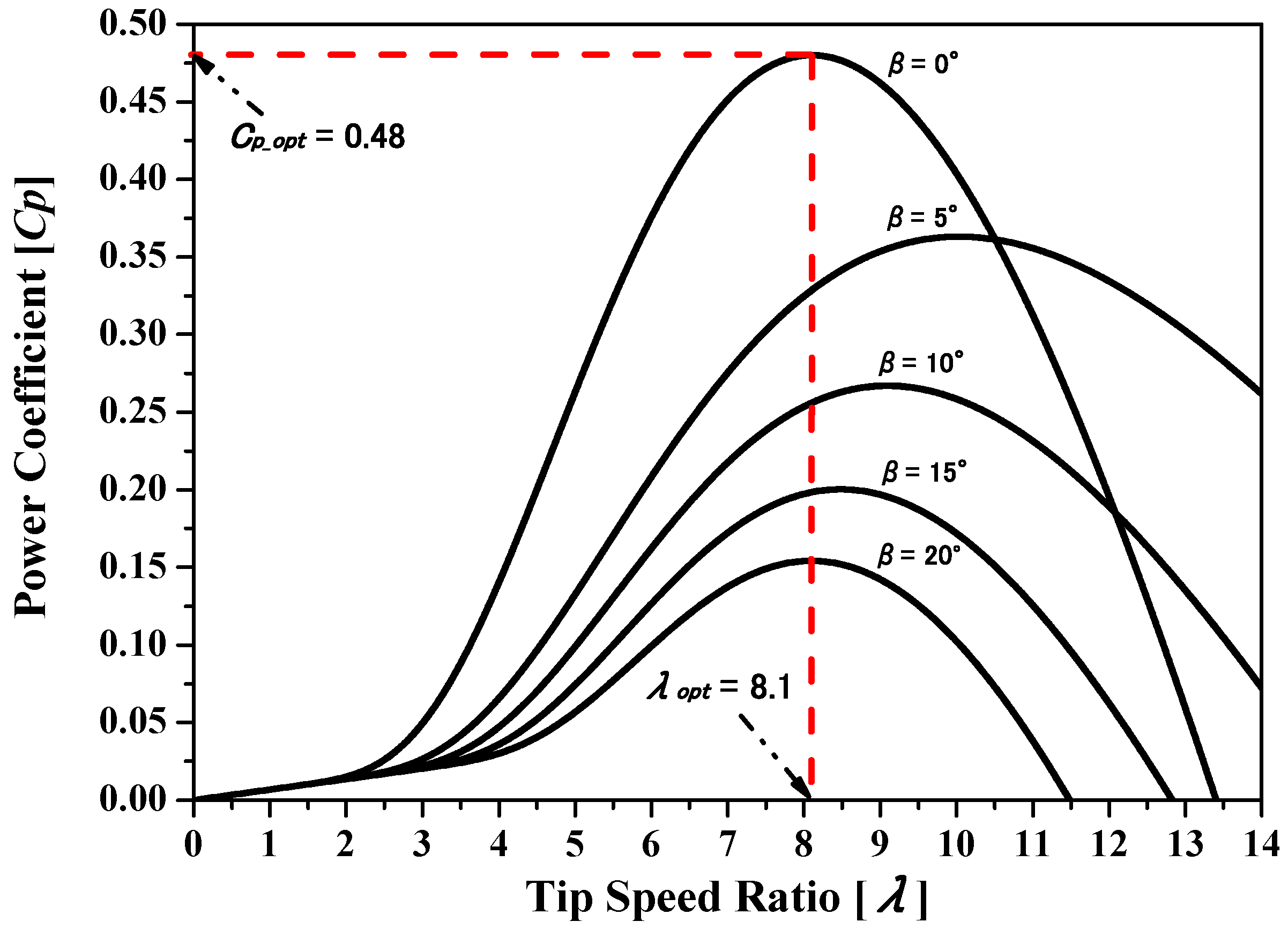
where , , and represent the tip speed ratio, WT torque, and pitch angle, respectively. Furthermore, – present the characteristic coefficients of the WT [34], and presents the rotational speed of the WT.
Figure 2 illustrates the characteristics that are achieved by solving Equation (2) with various values. The optimum power coefficient and the optimum tip speed ratio are equal to 0.48 and 8.1, respectively, when the is equal to zero degrees.
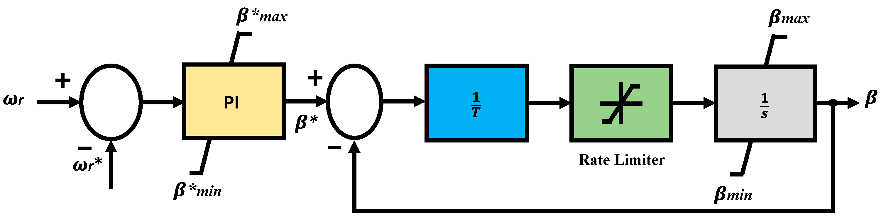
Figure 3 and Figure 4 illustrate the designs of the FSWT and VSWT blade pitch control schemes, respectively [35]. The output power of SCIG was controlled by the pitch controller in FSWT so that it did not surpass the rated power and in VSWT, the pitch controller regulates the rotor speed of the DFIG so that it did not surpass the nominal condition. A first-order transfer function consisting of a pitch rate limiter characterized the pitch actuator control loop. Moreover, to control the tracking error, a PI controller was used.
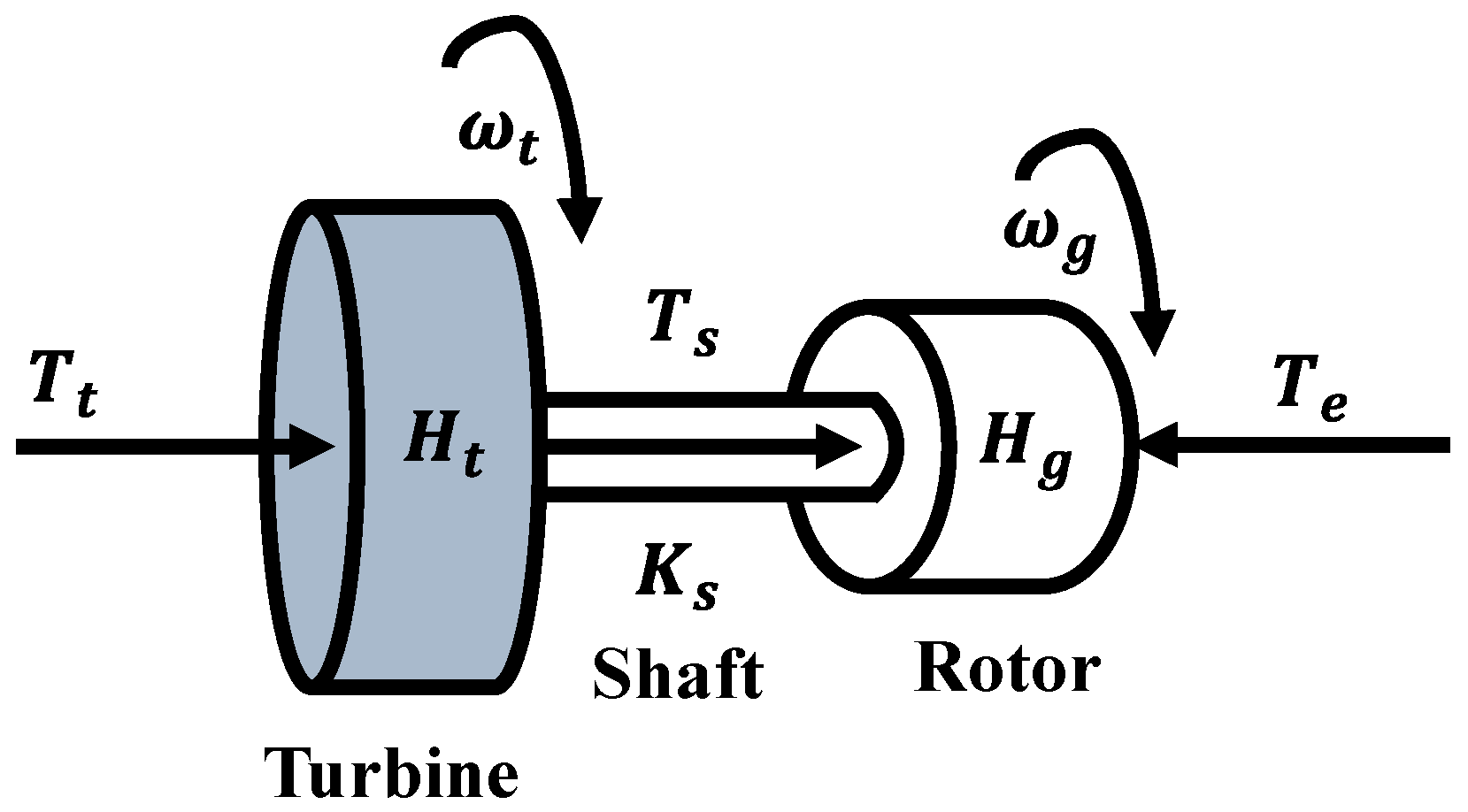
Since the model of the two-mass shaft was adequate for the dynamic study of grid-tied WTs, therefore, it was used in this research as indicated in Figure 5 [36]. The motion laws are defined as:
Here, mechanical torque and equivalent turbine blade inertia transferred to the generator side is denoted as and respectively. Electromagnetic torque is denoted as , the rotational speed of turbine and generator are denoted as and , sequentially. represents the shaft angular displacement between the two ends. The stiffness of the shaft is denoted as , and stands for the generator inertia.
4. Design of the DFIG System
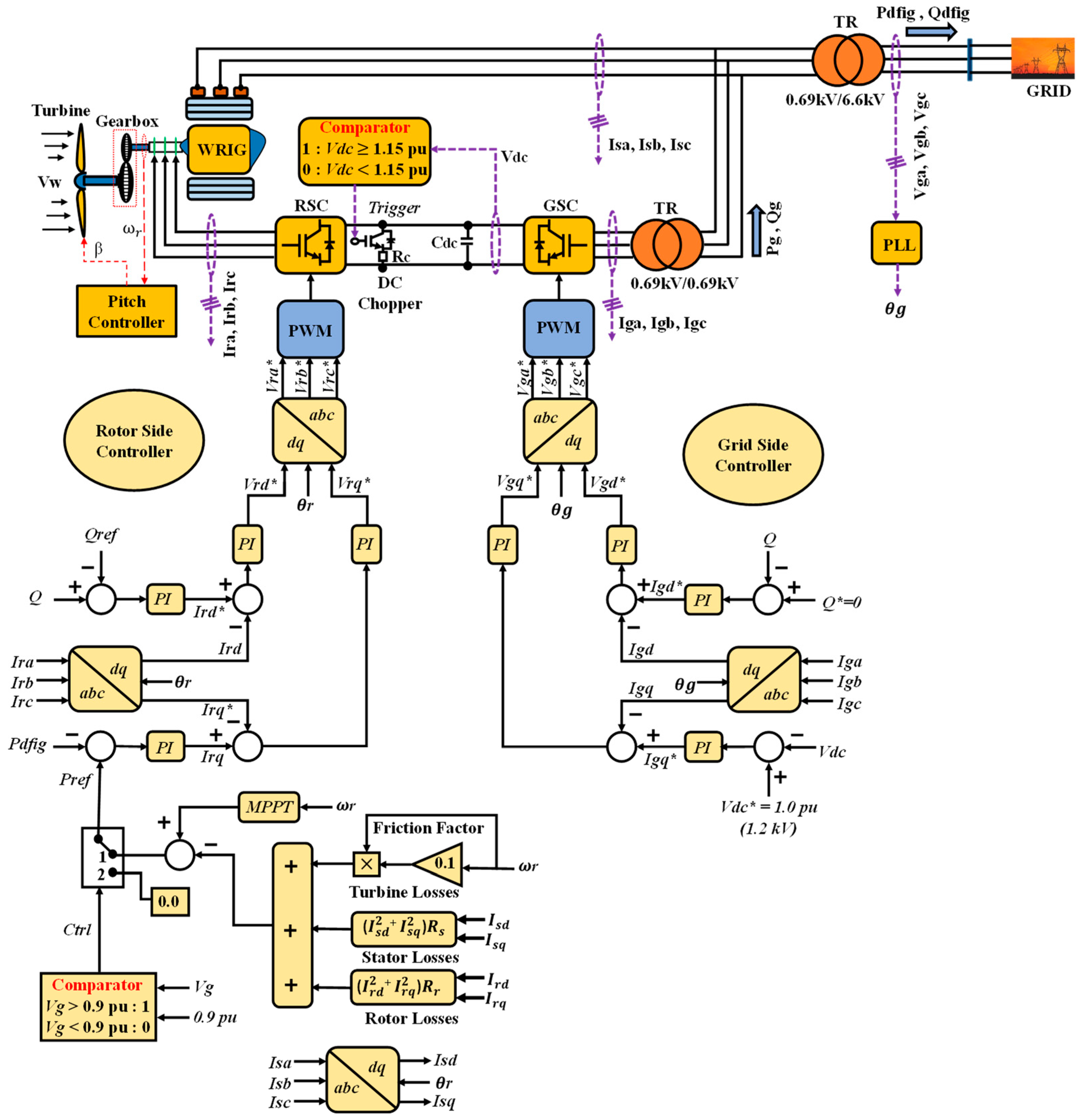
Figure 7 illustrates the arrangement of VSWT-DFIG together with its control strategy. Here, an aerodynamic WT scheme consisting of a drive train, pitch angle controller, wound rotor induction generator (WRIG), and an AC/DC/AC converter formed from two levels of insulated gate bipolar transistors (IGBTs) operated by the rotor side and grid side controllers comprised the overall system. Nevertheless, WRIG was connected to the WT, which transfigured the WP into electrical power. The rotor position and . were computed using the WRIG rotor shaft. As shown in Figure 7, the stator terminal was firmly tied to the power grid, while the rotor was attached to the grid using RSC and GSC. The rating of the power converter was 30% of the WRIG. The pulse width modulation (PWM) approach was imposed in this research, and the carrier frequency was taken 3.0 kHz for AC/DC/AC converter. The DC-Link circuit contained a DC chopper. The comparator block controlled it, enabling the DC chopper switch whenever the DC-link voltage exceeded or equaled the predetermined limit (Vdc 1.15 pu). Moreover, the rated DC-Link voltage was 1.2 kV.
4.1. DFIG Model
The DFIG system was specified in the synchronous reference frame. The d and q-axis stator and rotor voltages are derived below:
Here, the resistance and self-inductance of stator and rotor winding are illustrated as , , and , , sequentially. is denoted as mutual inductance. The currents of the stator and rotor are denoted as , , , and respectively. Finally, is presented as the angular frequency of the grid.
4.2. Proposed Rotor-Side Converter (RSC) Control Scheme
The RSC was controlled by the RSC controller, as presented in Figure 7. The control mechanism involved four PI controllers to balance numerous errors. The outer loops were responsible for extracting MPPT power from the DFIG and controlling reactive power. The inner loops regulated the d- and q-axis currents. The turbine, rotor, and stator losses were taken into account as stated in the below equations to regulate active power.
Here, Ps, Pr, and Ptl represent the stator, rotor, and turbine losses, respectively. By considering all these losses, the active power extracted could be more realistic.
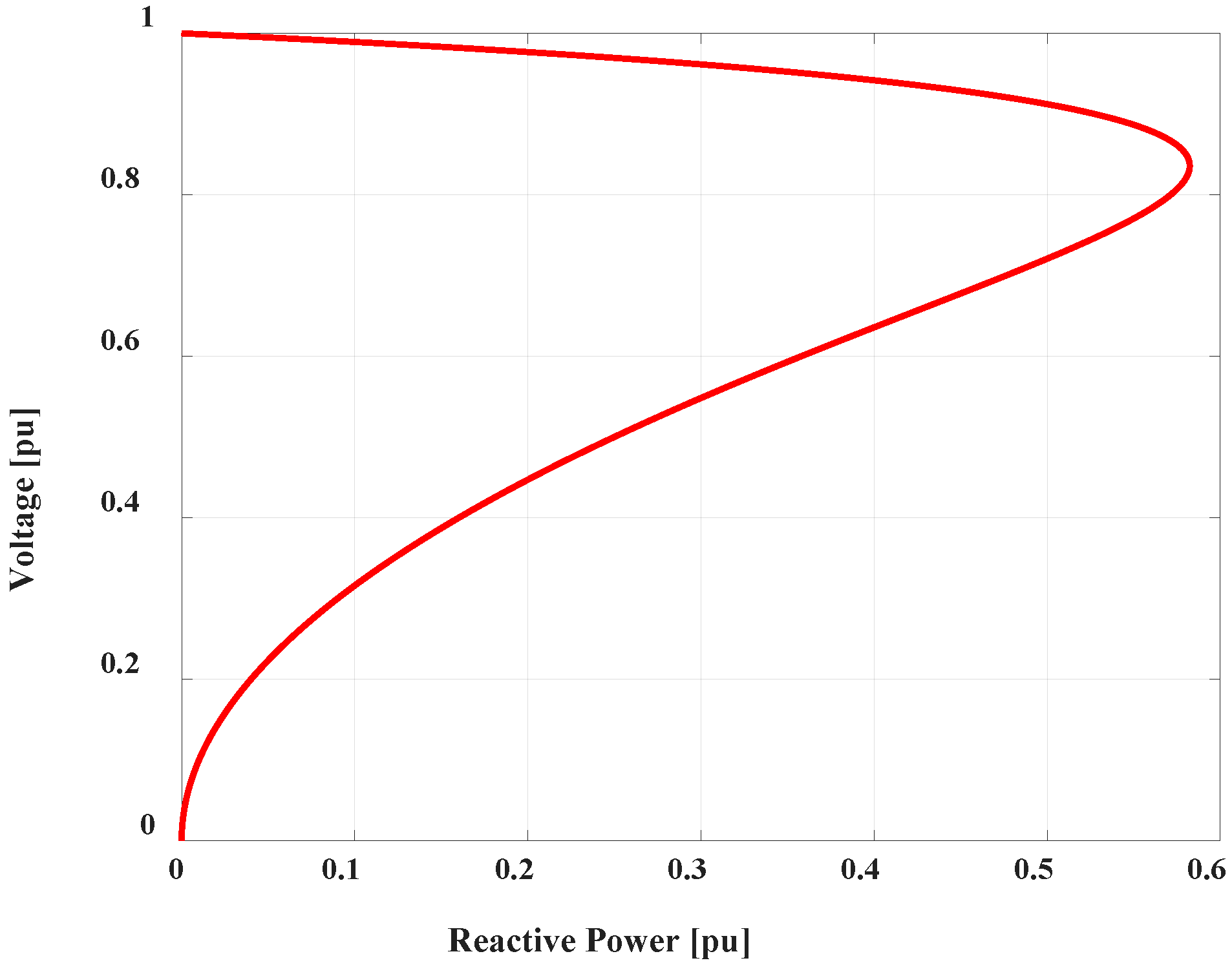
In this study, the proposed controller focused on the maximization of reactive power injection. This was accomplished by regulating the reactive power based on the voltage dip at the common coupling point. The reference reactive power generated based on the voltage dip can be computed as follows [37,38]:
where S represents the rated apparent power, and represent the terminal voltage and pre-fault voltage (1.0 pu) of DFIG, respectively. Based on the equation, when terminal voltage was 1.0 pu at the steady-state period, the reactive power injection would be zero; thus, it ensured the unity power factor operation. Further, based on Equation (14), the voltage vs. reactive power characteristics curve was derived in Figure 8. Based on the diagram, the reactive power could be generated up to 0.5824 pu at the voltage level of 0.836 pu.
During the fault period, the main objective was to maximize the reactive power injection rather than active power to limit the apparent power rating. Therefore, a comparator block was also embedded in the proposed control mechanism. This comparator sent a zero signal to make the active power transfer to gird zero when the terminal voltage dropped 90% of its rated value. The active power resumed its delivery to the grid when the terminal voltage was above 90%. By following this technique, the reactive power delivered could be enhanced, and effective LVRT competency could be ensured.
4.3. Grid-Side Converter (GSC) Control Scheme
Figure 7 also illustrates the GSC controller and compensates for various error signals, and it contains four PI controllers. Additionally, d-axis (Igd) and q-axis (Igq) current components regulated the GSC reactive power (Q) and DC-link voltage (Vdc), sequentially. Additionally, the reference reactive power was fixed to zero, and the reference DC-link voltage was fixed to 1.2 kV (1.0 pu).
5. Simulation Results
PSCAD/EMTDC software was used to perform the simulation analysis on the system depicted in Figure 1. Moreover, to analyze the simulation performance, the most severe triple-line-to-ground (3LG) fault was appraised to be a network disruption near the infinite bus with a simulation run time of 10 s that is illustrated in Figure 1. The fault arose at 0.1 s and the total fault time span was 0.1 s. At 0.2 s, the circuit breakers (CBs) on the faulted line were tripped to detach it from the power grid. The fault was assumed to have been cleared, and the CBs were reclosed at 1.0 s. Since the transient stability analysis period was so short, it was assumed that the wind speed did not vary significantly during this interval. As a consequence, the wind speed utilized to individual WT remained constant.
To justify the feasibility of the proposed PI-controlled RSC controller of DFIG, simulations were conducted for two cases:
Case 1: Conventional cascaded scheme of RSC of DFIG presented in [33].
Case 2: Proposed RSC controller of DFIG illustrated in Section 4.
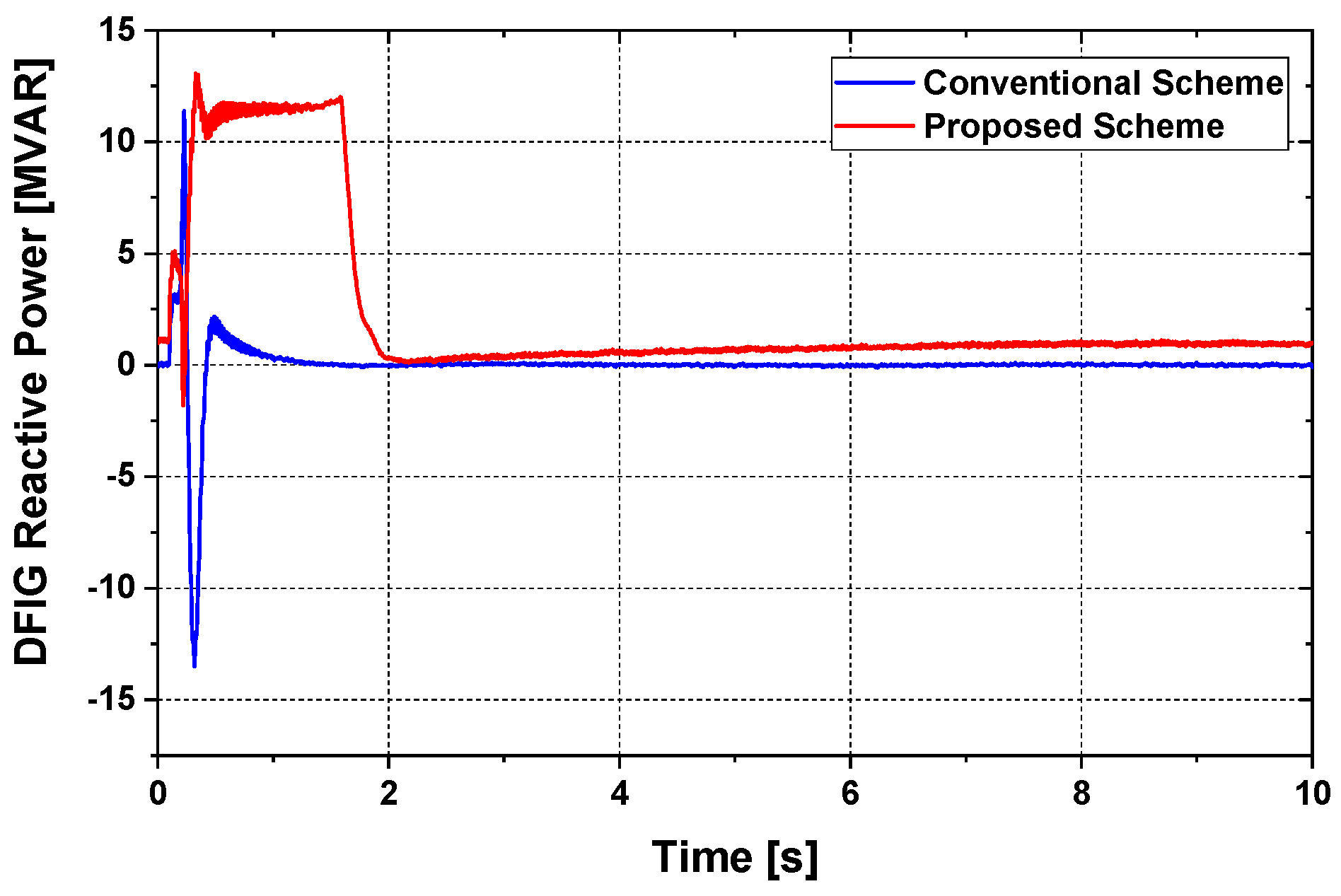
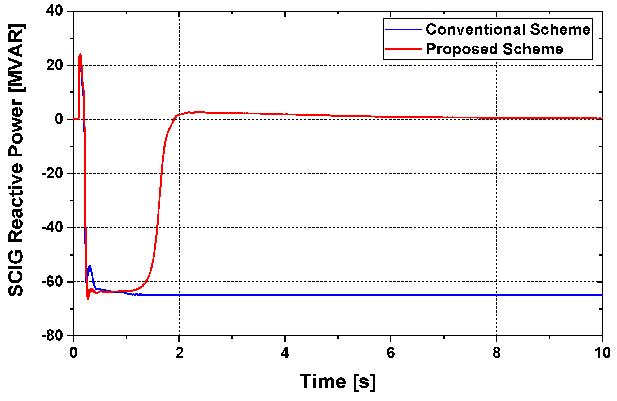
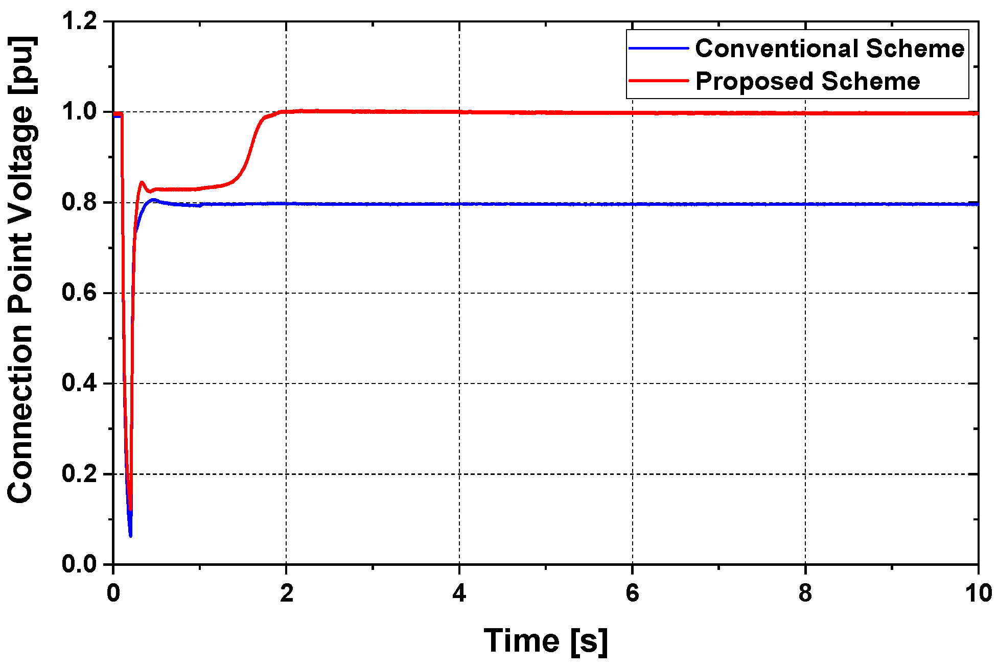
The responses to reactive power from DFIG and SCIG are indicated in Figure 9 and Figure 10. It could be observed that during the transition phase, the DFIG provided SCIG with an adequate percentage of reactive power in Case 2. Therefore, the voltage at the connection point recovered more rapidly to the rated condition in Case 2, and the system became stable, which was presented in Figure 11. The reactive power in Case 2 rose significantly as soon as the terminal voltage decayed at 0.1 s (approximately), and it supplied around 12 MVAR until the terminal voltage reached the normal condition, as indicated in Figure 9 and Figure 11. When the terminal voltage resumed to 1.0 pu, the reactive power also reached its pre-fault condition.
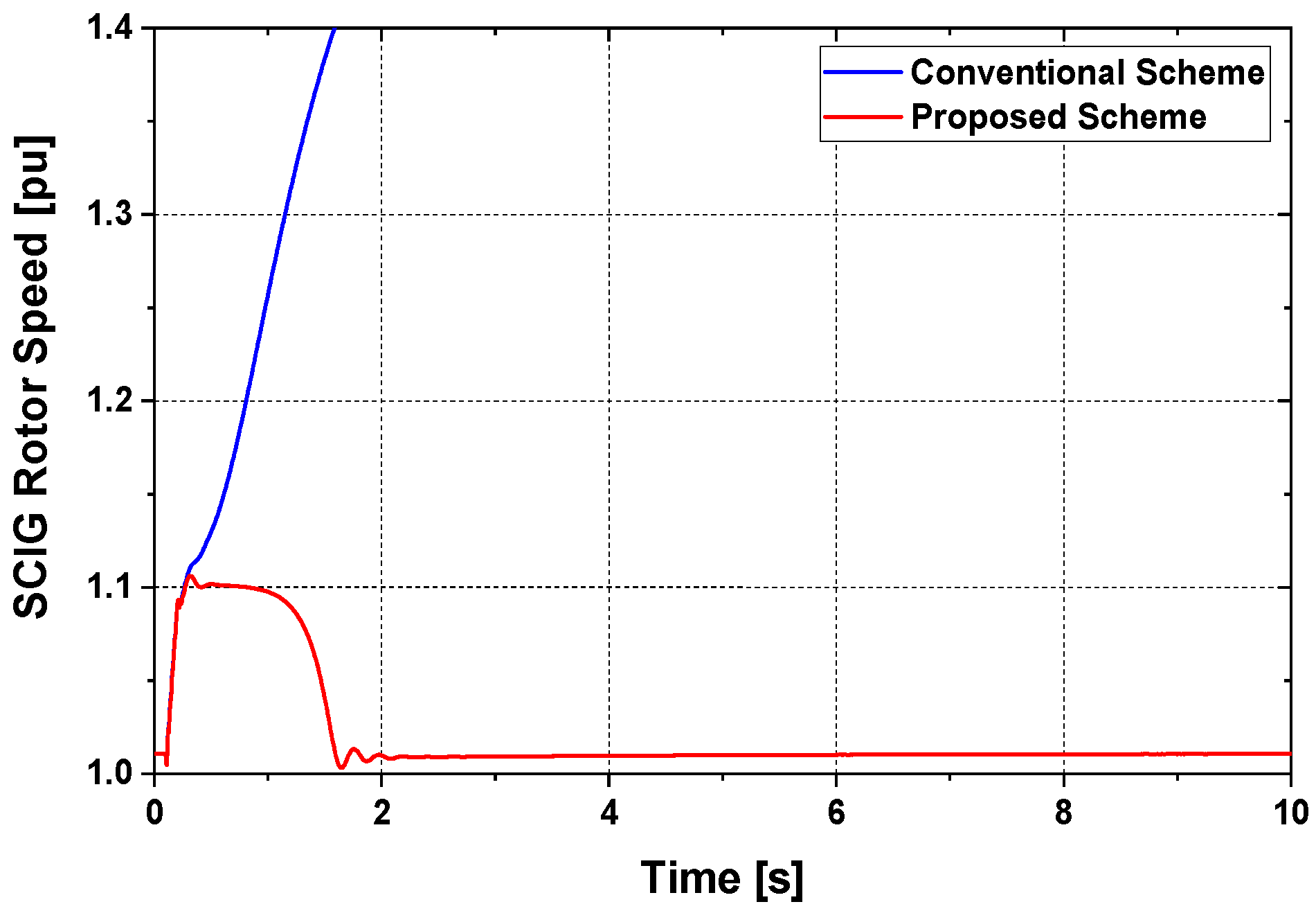
However, in Case 1, as described in Figure 9 and Figure 10, the DFIG could not supply SCIG with a sufficient amount of reactive power. As a consequence, the terminal voltage, in this case, could not regain the rated value. Hence, the grid code requirement was not fulfilled in Case 1, and the system was unstable. Figure 12 depicts the rotor speed response of the SCIG, which revealed that in Case 2, the response was stable. However, in Case 1, it was unstable. This was because the capacitor bank, which was attached to the terminal of SCIG, was not enough to inject sufficient reactive power at the transient state. Thus, the developed electromagnetic torque decreased, and the rotor speed increased, as indicated in Case 1. However, in Case 2, the proposed method of DFIG helped to inject reactive power from the DFIG and made the rotor speed stable.
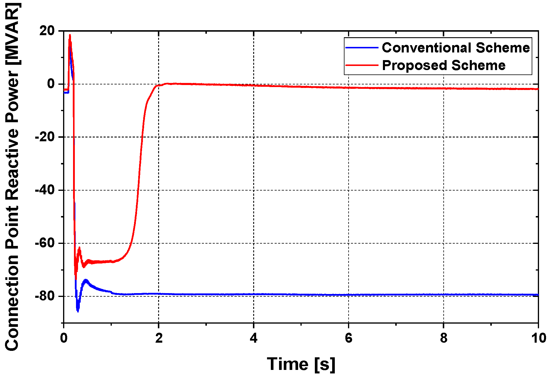
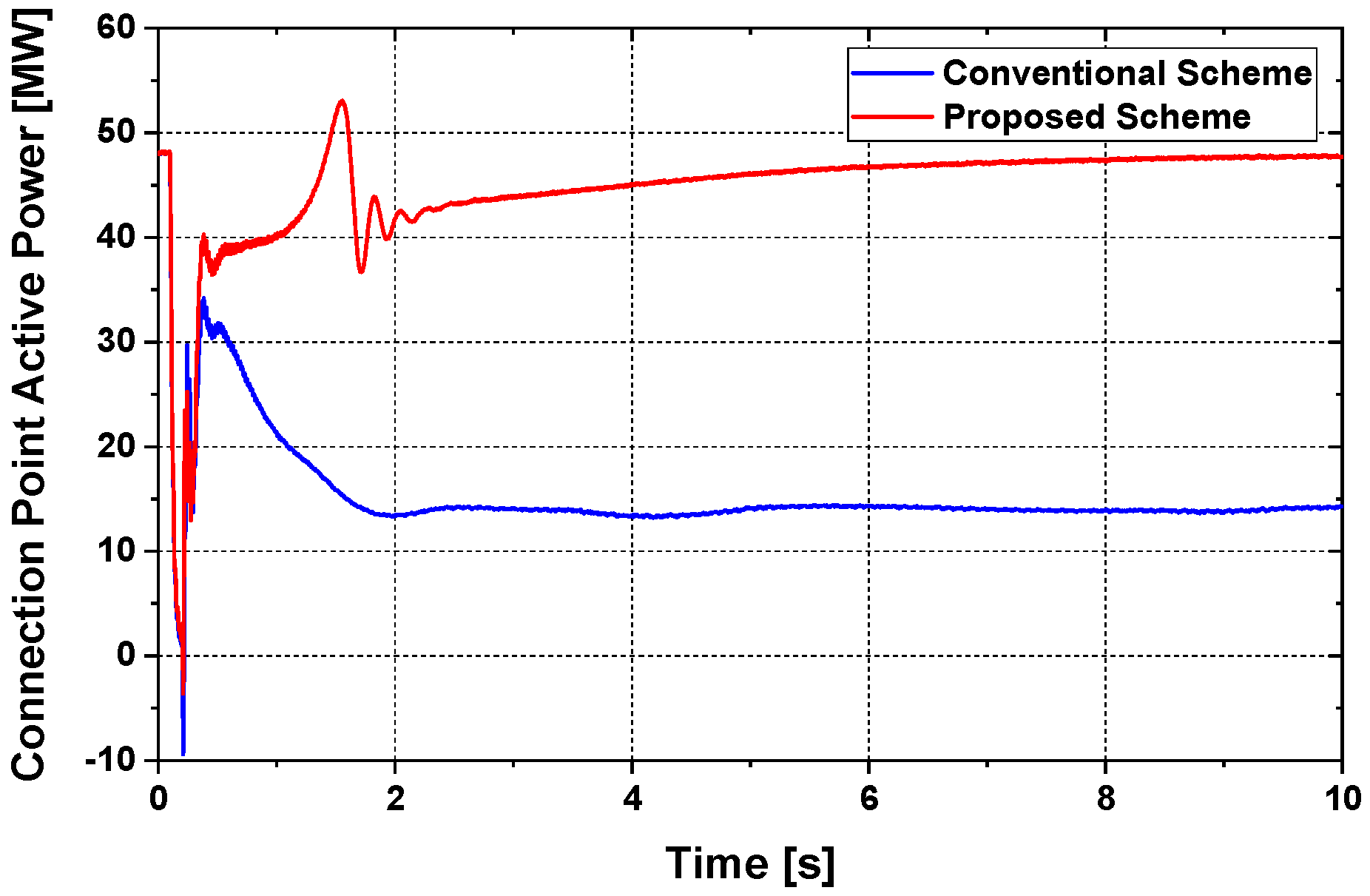
Figure 13 and Figure 14 represent the reactive and active power response of the connection point. It was seen from both figures; the reactive and active powers were stable in Case 2.
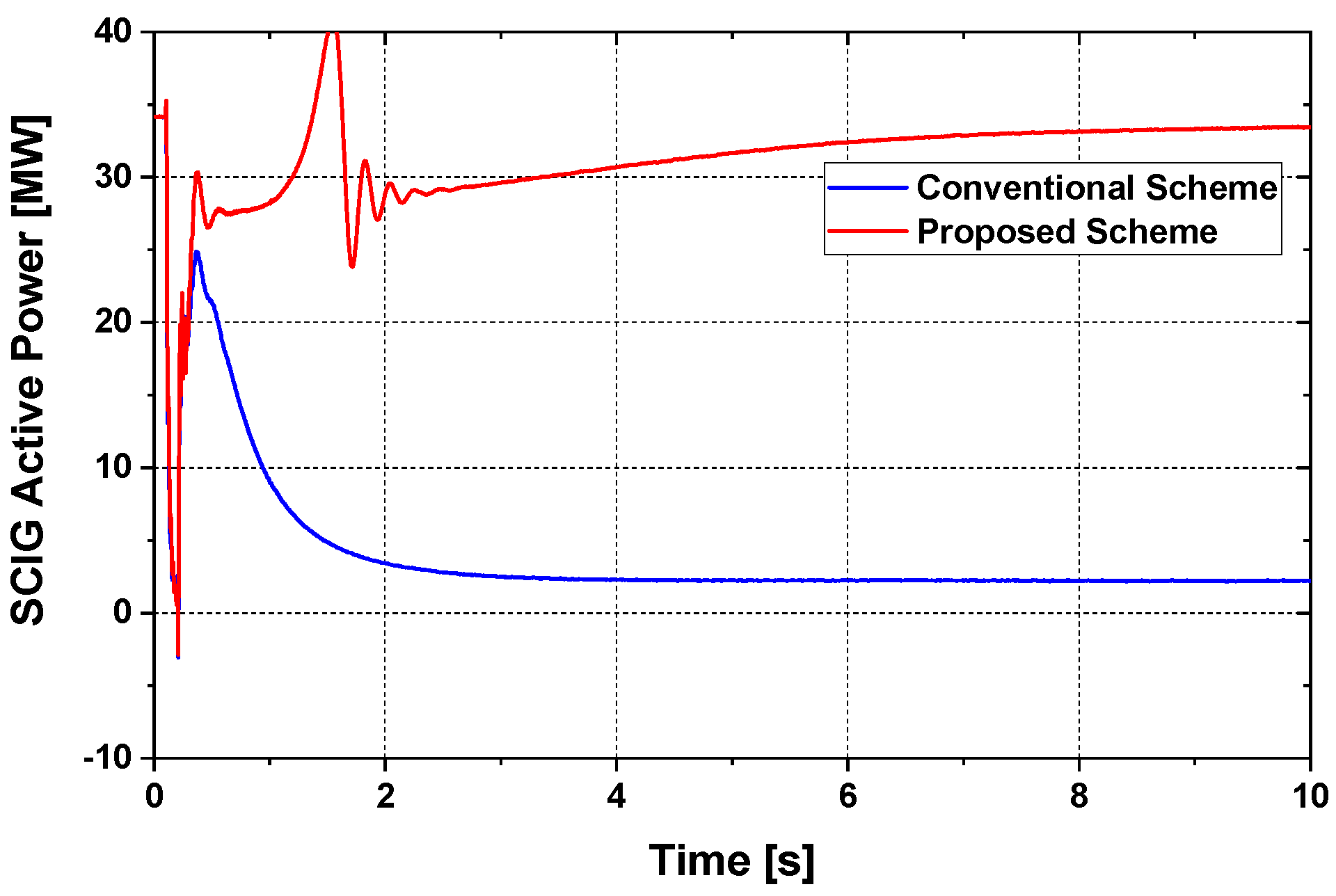
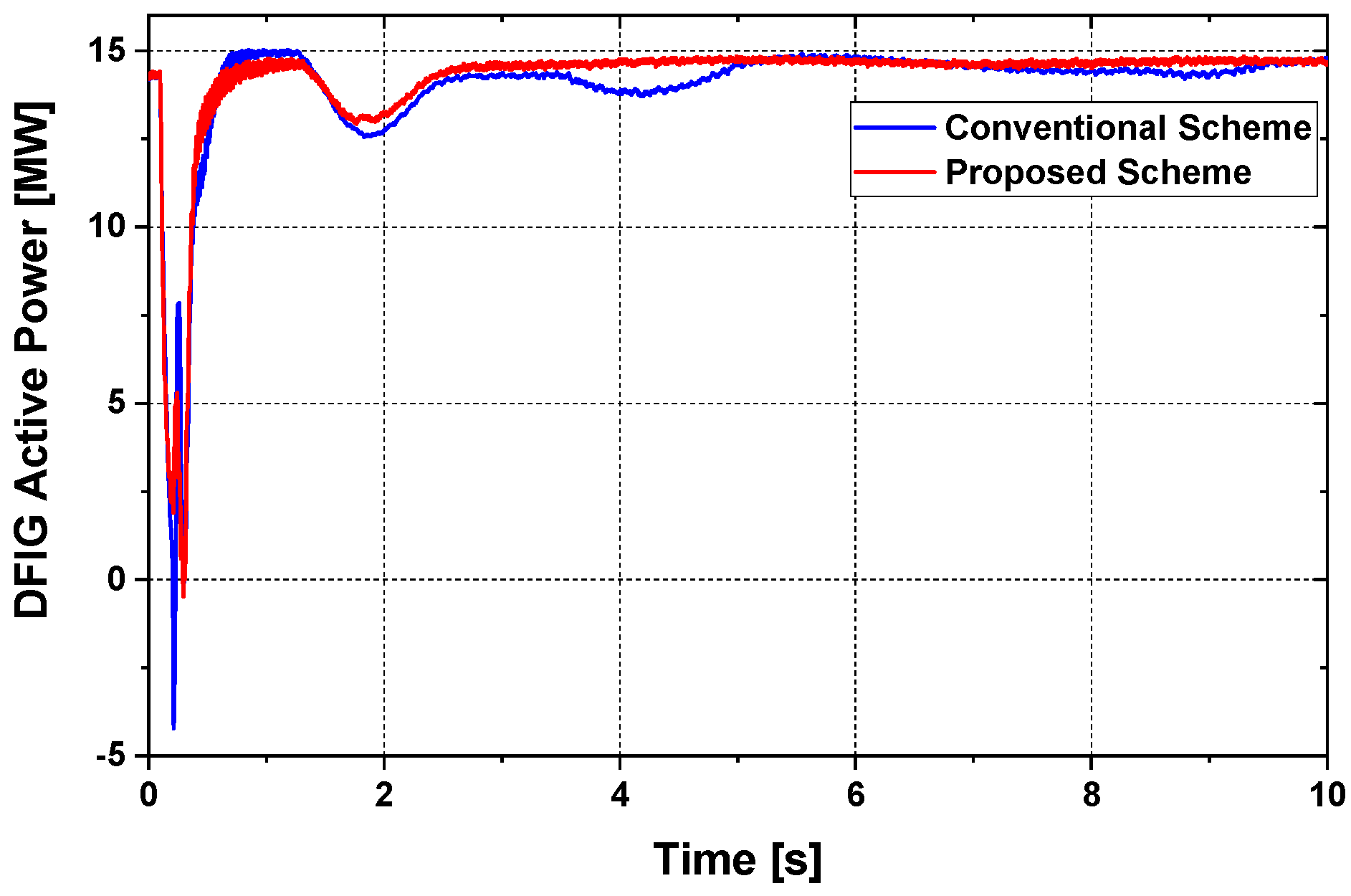
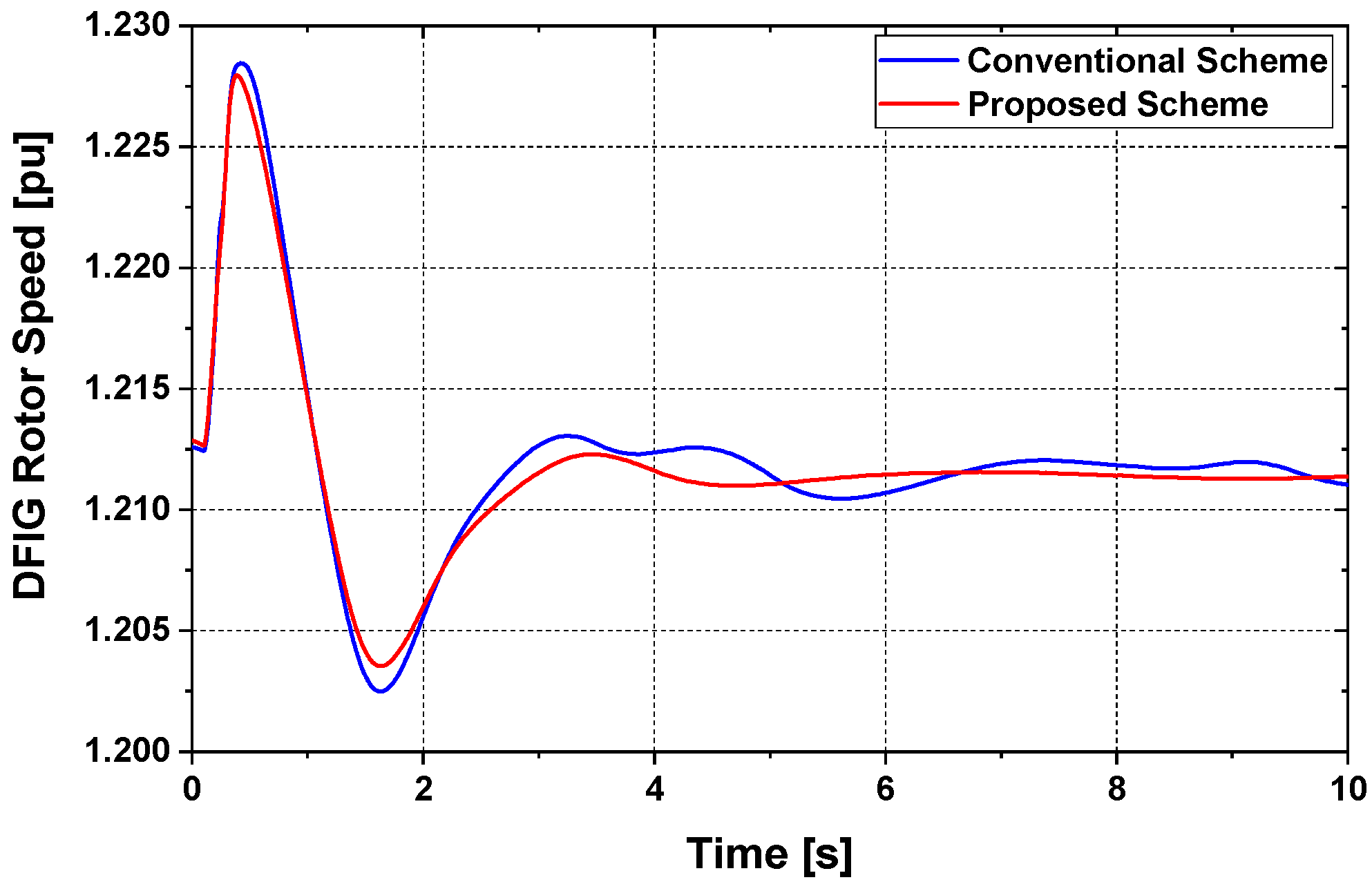
Figure 15 and Figure 16 represent the response of active power of SCIG and DFIG, respectively, where Case 2 showed better performance. Figure 17 illustrated the rotor speed response of DFIG.
Depending on the above observations, it was possible to conclude that the proposed DFIG controller could effectively stabilize the grid-tied WF during transient periods. Furthermore, it ensured LVRT capability.
6. Conclusions
The current study proposed partial integration of the DFIG with the proposed rotor-side controller based on the PI controller to improve the LVRT effectiveness of the SCIG-based WF. Furthermore, a comparison of the suggested and conventional rotor side controllers was performed. According to the simulation outcomes and performance evaluations, the following aspects of the proposed approach were remarkable:
- (1)
- The proposed controller of DFIG with a minimum power rating could stabilize the SCIG with a higher power rating during a fault state.
- (2)
- The implementation expense could be minimized by integrating a limited number of DFIGs with the suggested control scheme and a wide scale of SCIGs into a WF.
- (3)
- The proposed RSC controller of the DFIG system could keep the terminal voltage at the rated condition during the transient state by transferring an adequate amount of reactive power into the grid.
Therefore, the combined installation of the proposed DFIG consisting of relatively low power rating with SCIG based WF could enhance the LVRT capability as well as the system stability.
In future work, the frequency control method of hybrid WF could be a strong candidate.
Author Contributions
J.M.A., M.R.H. and M.A.M. prepared the theoretical conceptions and designed the proposed RSC controller of the DFIG system. J.M.A. and M.R.H. executed the simulation studies and wrote the manuscript. All authors have read and agreed to the published version of the manuscript.
Funding
This research received no external funding.
Conflicts of Interest
The authors declare no conflict of interest.
References
- Global Wind Energy Council (GWEC). Annual Market Update 2019, Global Wind Report. 2019. Available online: http://www.gwec.net/ (accessed on 25 February 2021).
- Global Wind Energy Council (GWEC). Global Wind Energy Outlook 2016: Wind Power to Dominate Power Sector Growth 2016. Available online: http://www.gwec.net/ (accessed on 27 February 2021).
- Rezaie, H.; Kazemi-Rahbar, M.H. Enhancing voltage stability and LVRT capability of a wind-integrated power system using a fuzzy-based SVC. Eng. Sci. Technol. Int. J. 2019, 22, 827–839. [Google Scholar] [CrossRef]
- Ali, M.A.S.; Mehmood, K.K.; Baloch, S.; Kim, C.H. Modified rotor-side converter control design for improving the LVRT capability of a DFIG-based WECS. Electr. Power Syst. Res. 2020, 186, 106403. [Google Scholar] [CrossRef]
- Heydari-Doostabad, H.; Khalghani, M.R.; Khooban, M.H. A novel control system design to improve LVRT capability of fixed speed wind turbines using STATCOM in presence of voltage fault. Int. J. Electr. Power Energy Syst. 2016, 77, 280–286. [Google Scholar] [CrossRef]
- Abo-Khalil, A.G. Impacts of Wind Farms on Power System Stability. In Wind Farm; Intechopen: London, UK, 2013; ISBN 980-953-307-562-9. [Google Scholar]
- Ahsan, S.; Siddiqui, A.S. Dynamic compensation of real and reactive power in wind farms using STATCOM. Perspect. Sci. 2016, 8, 519–521. [Google Scholar] [CrossRef] [Green Version]
- Muyeen, S.M.; Tamura, J.; Murata, T. Stability Augmentation of a Grid-Connected Wind Farm; Springer Science & Business Media: Berlin/Heidelberg, Germany, 2008. [Google Scholar]
- Mahela, O.P.; Gupta, N.; Khosravy, M.; Patel, N. Comprehensive Overview of Low Voltage Ride Through Methods of Grid Integrated Wind Generator. IEEE Access 2019, 7, 99299–99326. [Google Scholar] [CrossRef]
- Muyeen, S.M.; Mannan, M.A.; Ali, M.H.; Takahashi, R.; Murata, T.; Tamura, J. Stabilization of wind turbine generator system by STATCOM. IEEJ Trans. Power Energy 2006, 126, 1073–1082. [Google Scholar] [CrossRef] [Green Version]
- Shi, J.; Furness, I.; Kalam, A.; Shi, P. On low voltage ride-through and stability of wind energy conversion systems with FACTS devices. In Proceedings of the 2013 Australasian Universities Power Engineering Conference (AUPEC), Hobart, TAS, Australia, 29 September–3 October 2013; IEEE: New York, NY, USA; pp. 1–6. [Google Scholar]
- Aly, M.M.; Mohamed, E.A.; Salama, H.S.; Said, S.M.; Abdel-Akher, M.; Qudaih, Y. A developed voltage control strategy for unbalanced distribution system during wind speed gusts using SMES. Energy Procedia 2016, 100, 271–279. [Google Scholar] [CrossRef] [Green Version]
- Muyeen, S.M.; Takahashi, R.; Ali, M.H.; Murata, T.; Tamura, J. Transient stability augmentation of power system including wind farms by using ECS. IEEE Trans. Power Syst. 2008, 23, 1179–1187. [Google Scholar] [CrossRef]
- Rashad, A.; Kamel, S.; Jurado, F. Stability improvement of power systems connected with developed wind farms using SSSC controller. Ain Shams Eng. J. 2018, 9, 2767–2779. [Google Scholar] [CrossRef]
- Ananth, D.V.N.; Kumar, G.N. Fault ride-through enhancement using an enhanced field oriented control technique for converters of grid connected DFIG and STATCOM for different types of faults. ISA Trans. 2016, 62, 2–18. [Google Scholar] [CrossRef]
- Kartijkolaie, H.S.; Radmehr, M.; Firouzi, M. LVRT capability enhancement of DFIG-based wind farms by using capacitive DC reactor-type fault current limiter. Int. J. Electr. Power Energy Syst. 2018, 102, 287–295. [Google Scholar] [CrossRef]
- Zhu, D.; Zou, X.; Dong, W.; Jiang, C.; Kang, Y. Disturbance feedforward control for type-3 wind turbines to achieve accurate implementation of transient control targets during LVRT. Int. J. Electr. Power Energy Syst. 2020, 119, 105954. [Google Scholar] [CrossRef]
- Zribi, M.; Alrifai, M.; Rayan, M. Sliding mode control of a variable-speed wind energy conversion system using a squirrel cage induction generator. Energies 2017, 10, 604. [Google Scholar] [CrossRef] [Green Version]
- Duong, M.Q.; Leva, S.; Mussetta, M.; Le, K.H. A comparative study on controllers for improving transient stability of DFIG wind turbines during large disturbances. Energies 2018, 11, 480. [Google Scholar] [CrossRef] [Green Version]
- Okedu, K.; Muyeen, S.M.; Takahashi, R.; Tamura, J. Wind Farm Stabilization by using DFIG with Current Controlled Voltage Source Converter taking Grid Codes into Consideration. IEEJ Trans. Power Energy 2012, 132, 251–259. [Google Scholar] [CrossRef] [Green Version]
- Abdeddaim, S.; Betka, A. Optimal Tracking and Robust Power Control of the DFIG Wind Turbine. Int. J. Electr. Power Energy Syst. 2013, 49, 234–242. [Google Scholar] [CrossRef]
- Mohammadi, J.; Vaez-Zadeh, S.; Afsharnia, S.; Daryabeigi, E.A. Combined Vector and Direct Power Control for DFIG-Based Wind Turbines. IEEE Trans. Sustain. Energy 2014, 5, 767–775. [Google Scholar] [CrossRef]
- Gebru, F.M.; Khan, B.; Alhelou, H.H. Analyzing low voltage ride through capability of doubly fed induction generator based wind turbine. Comput. Electr. Eng. 2020, 86, 106727. [Google Scholar] [CrossRef]
- Hossain, M.E. Low voltage ride-through capability improvement methods for DFIG based wind farm. J. Electr. Syst. Inf. Technol. 2018, 5, 550–561. [Google Scholar] [CrossRef]
- Jaladi, K.K.; Sandhu, K.S. Real-time simulator based hybrid controller of DFIG-WES during grid faults design and analysis. Int. J. Electr. Power Energy Syst. 2020, 116, 105545. [Google Scholar] [CrossRef]
- Hu, S.; Lin, X.; Kang, Y.; Zou, X. An improved low-voltage ride-through control strategy of doubly fed induction generator during grid faults. IEEE Trans. Power Electron. 2011, 26, 3653–3665. [Google Scholar] [CrossRef]
- Ibrahim, A.O.; Nguyen, T.H.; Lee, D.C.; Kim, S.C. A fault ride-through technique of DFIG wind turbine systems using dynamic voltage restorers. IEEE Trans. Energy Convers. 2011, 26, 871–882. [Google Scholar] [CrossRef]
- Jin, J.X.; Yang, R.H.; Zhang, R.T.; Fan, Y.J.; Xie, Q.; Chen, X.Y. Combined low voltage ride through and power smoothing control for DFIG/PMSG hybrid wind energy conversion system employing a SMES-based AC-DC unified power quality conditioner. Int. J. Electr. Power Energy Syst. 2021, 128, 106733. [Google Scholar] [CrossRef]
- Manohar, G.; Venkateshwarlu, S.; Laxmi, A.J. A DFIG-based wind energy conversion system (WECS) for LVRT enhancement using a hybrid approach: An efficient MEHRFA technique. Soft Comput. 2021, 25, 2559–2574. [Google Scholar] [CrossRef]
- Gounder, Y.K.; Nanjundappan, D.; Boominathan, V. Enhancement of transient stability of distribution system with SCIG and DFIG based wind farms using STATCOM. IET Renew. Power Gener. 2016, 10, 1171–1180. [Google Scholar] [CrossRef]
- Lu, Y. Adaptive-Fuzzy Control Compensation Design for Direct Adaptive Fuzzy Control. IEEE Trans. Fuzzy Syst. 2018, 26, 3222–3231. [Google Scholar] [CrossRef]
- Errouissi, R.; Al-Durra, A.; Muyeen, S.M.; Leng, S.; Blaabjerg, F. Offset-Free Direct Power Control of DFIG Under Continuous-Time Model Predictive Control. IEEE Trans. Power Electron. 2017, 32, 2265–2277. [Google Scholar] [CrossRef]
- Rosyadi, M.; Umemura, A.; Takahashi, R.; Tamura, J.; Uchiyama, N.; Ide, K. Simplified Model of Variable Speed Wind Turbine Generator for Dynamic Simulation Analysis. IEEJ Trans. Power Energy 2015, 135, 538–549. [Google Scholar] [CrossRef]
- Matlab Documentation Center. Available online: https://www.mathworks.com/help/ (accessed on 23 April 2021).
- Liu, J.; Rosyadi, M.; Umemura, A.; Takahashi, R.; Tamura, J. A control method of permanent magnet wind generators in grid connected wind farm to damp load frequency oscillation. IEEJ Trans. Power Energy 2014, 134, 393–398. [Google Scholar] [CrossRef]
- Rashid, G.; Ali, M.H. Fault ride through capability improvement of DFIG based wind farm by fuzzy logic controlled parallel resonance fault current limiter. Electr. Power Syst. Res. 2017, 146, 1–8. [Google Scholar] [CrossRef]
- Yagami, M.; Ichinohe, M.; Tamura, J. Enhancement of Power System Transient Stability by Active and Reactive Power Control of Variable Speed Wind Generators. Appl. Sci. 2020, 10, 8874. [Google Scholar] [CrossRef]
- Jozuka, T.; Iriguchi, T.; Komami, S. Value Comparison Between FRT and DVS Functions on Renewable Energy. Electr. Eng. Jpn. 2018, 205, 33–40. [Google Scholar] [CrossRef]
Figure 1.
Power system model.

Figure 2.
characteristics with various .

Figure 3.
Pitch control scheme for fixed-speed wind turbines (FSWT).

Figure 4.
Pitch control scheme for variable-speed wind turbines (VSWT).

Figure 5.
Drive train model.

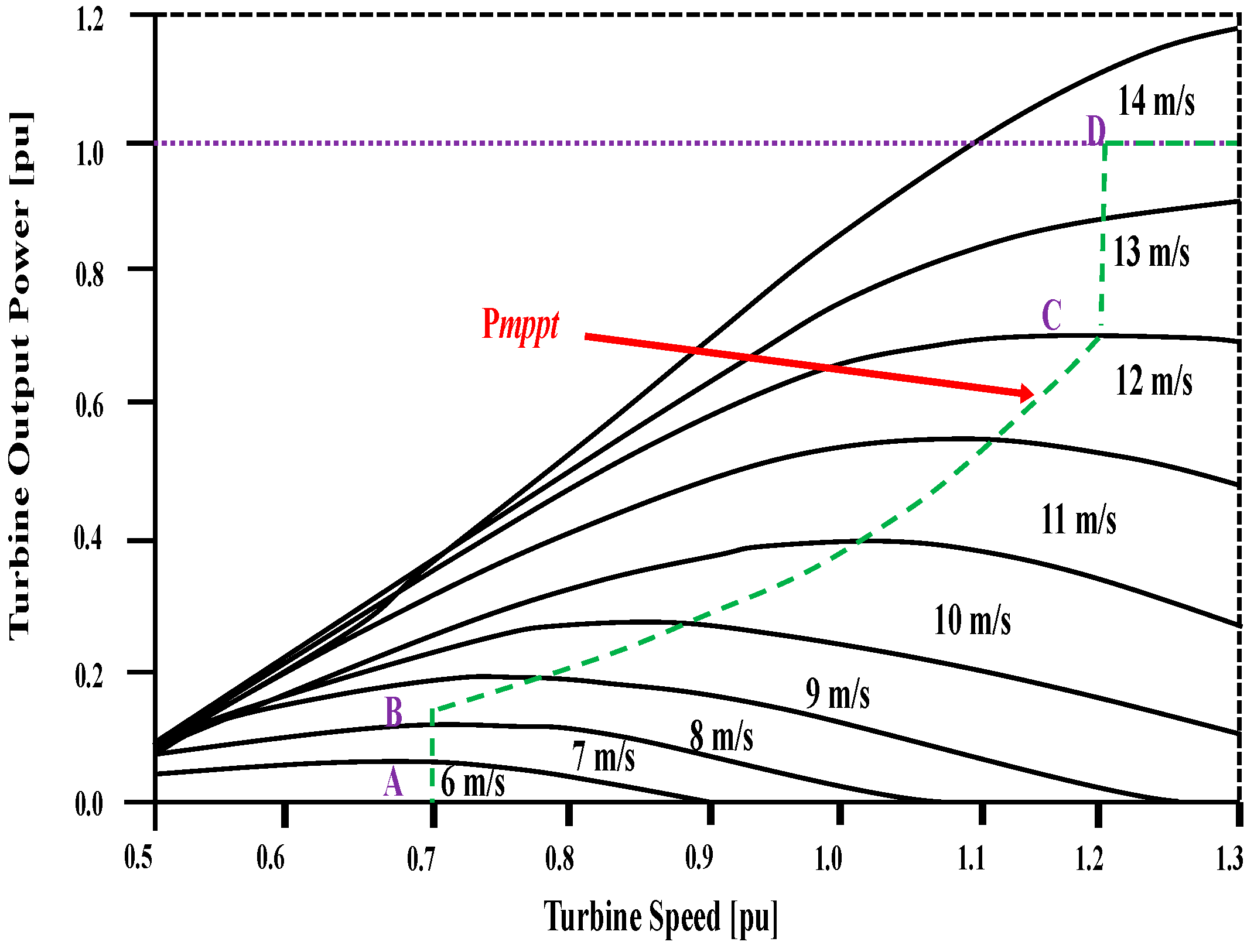
Figure 6.
Characteristics of a wind turbine with maximum power point tracking (MPPT) for a doubly fed induction generator (DFIG).
Figure 6.
Characteristics of a wind turbine with maximum power point tracking (MPPT) for a doubly fed induction generator (DFIG).

Figure 7.
DFIG system with cascaded control strategies.

Figure 8.
Reactive power control scheme (voltage vs. reactive power characteristic curve).

Figure 9.
Reactive power response of DFIG.

Figure 10.
Reactive power response of SCIG.

Figure 11.
Voltage performance at the connection point.

Figure 12.
Rotor speed performance of SCIG.

Figure 13.
Reactive power response at the connection point.

Figure 14.
Active power response at the connection point.

Figure 15.
Active Power response of SCIG.

Figure 16.
Active Power response of DFIG.

Figure 17.
Rotor Speed performance of DFIG.


Table 1.
Parameters of wind generators.
| Doubly Fed Induction Generator (DFIG) | Squirrel Cage Induction Generator (SCIG) | ||
|---|---|---|---|
| MVA | 15 | MVA | 35 |
| (pu) | 0.007 | (pu) | 0.01 |
| (pu) | 0.005 | (pu) | 0.1 |
| (pu) | 0.171 | (pu) | 3.5 |
| (pu) | 0.156 | (pu) | 0.035 |
| (pu) | 2.9 | (pu) | 0.014 |
| - | - | (pu) | 0.03 |
| - | - | (pu) | 0.089 |
| - | - | H (s) | 1 |
Publisher’s Note: MDPI stays neutral with regard to jurisdictional claims in published maps and institutional affiliations. |
© 2021 by the authors. Licensee MDPI, Basel, Switzerland. This article is an open access article distributed under the terms and conditions of the Creative Commons Attribution (CC BY) license (https://creativecommons.org/licenses/by/4.0/).
Share and Cite
MDPI and ACS Style
Akanto, J.M.; Hazari, M.R.; Mannan, M.A. LVRT and Stability Enhancement of Grid-Tied Wind Farm Using DFIG-Based Wind Turbine. Appl. Syst. Innov. 2021, 4, 33. https://0-doi-org.brum.beds.ac.uk/10.3390/asi4020033
AMA Style
Akanto JM, Hazari MR, Mannan MA. LVRT and Stability Enhancement of Grid-Tied Wind Farm Using DFIG-Based Wind Turbine. Applied System Innovation. 2021; 4(2):33. https://0-doi-org.brum.beds.ac.uk/10.3390/asi4020033
Chicago/Turabian StyleAkanto, Jannatul Mawa, Md. Rifat Hazari, and Mohammad Abdul Mannan. 2021. "LVRT and Stability Enhancement of Grid-Tied Wind Farm Using DFIG-Based Wind Turbine" Applied System Innovation 4, no. 2: 33. https://0-doi-org.brum.beds.ac.uk/10.3390/asi4020033