Article

Spark Plasma Sintered Zirconia Ceramic Composites with Graphene-Based Nanostructures

by
Ángela Gallardo-López
1,*,
Cristina López-Pernía
1,
Carmen Muñoz-Ferreiro
1,
Carmen González-Orellana
1,
Ana Morales-Rodríguez
1 and
Rosalía Poyato
2
1
Departamento de Física de la Materia Condensada, ICMS, CSIC-Universidad de Sevilla, Avda Reina Mercedes s/n, 41012 Sevilla, Spain
2
Instituto de Ciencia de Materiales de Sevilla, ICMS, CSIC-Universidad de Sevilla, Avda. Américo Vespucio 49. 41092 Sevilla, Spain
*
Author to whom correspondence should be addressed.
Submission received: 27 June 2018 / Revised: 12 August 2018 / Accepted: 15 August 2018 / Published: 22 August 2018
(This article belongs to the Special Issue Advances in the Field of Nanostructured Ceramic Composites)

Abstract

:
The addition of graphene-based nanostructures (GBNs) can improve the inherent fragility of ceramics and provide them with improved electrical and thermal conductivities. However, both the starting material (ceramic matrix and GBNs) and the processing/sintering approach are crucial for the final composite microstructure and properties. This work focuses on the influence of the content and dimensions of the GBN filler (10 and 20 vol%; 3 and ~150 layers), the powder-processing conditions (dry versus wet), and the homogenization method (ultrasound sonication versus high-energy planetary ball milling) on GBN/tetragonal zirconia (3YTZP) composites. The microstructure and electrical properties of the spark plasma sintered (SPS) composites were quantified and analyzed. The highest microstructural homogeneity with an isotropic microstructure was achieved by composites prepared with thicker GBNs milled in dry conditions. A high content (20 vol%) of few-layered graphene as a filler maximizes the electrical conductivity of the composites, although it hinders their densification.

1. Introduction

Graphene-based nanostructures (GBNs) have recently come into scientific focus as a second phase in order to overcome the inherent fragility of ceramics. These two-dimensional graphitic nanostructures possess an extremely large specific surface area and Young’s modulus, together with exceptional electrical and thermal conductivities. However, the microstructure and performance of the composites are highly dependent on (i) the starting materials (ceramic used as a matrix and the quality, dimensions, and content of the GBN), and (ii) the processing approach and sintering conditions used. These features must be taken into account in order to obtain specific properties.
Concerning the starting materials, different advanced ceramics have been used as matrices, such as Si3N4 [1], which has the highest fracture toughness reported for 1.5 vol% GBN filler content [2], SiC [3,4], hydroxyapatite [5], alumina [6,7], and, more recently, zirconia [8,9].
The GBN properties are highly influenced by their dimensions, namely lateral size and thickness (the thickness is associated with the number of stacked graphene layers). That is the reason why some authors recommend the use of a systematic terminology to refer to the distinct members of the graphene family [10]. Only the nanostructures with fewer than 10 layers can be considered as multilayered graphene. For more than 10 layers, the GBN electronic structure is the same as for graphite. When the number of layers diminishes, as in few-layer graphene (FLG, with less than five layers), the electrical conductivity of the GBN increases, as does the spacing between the graphene layers. However, graphene aggregates with more than 10 stacked graphene layers and with a high specific surface area (2D-like nanostructures) are often commercialized as graphene nanoplatelets (GNPs). The cost of GBNs can also vary widely, depending on the synthesis route and on their dimensions. Therefore, an evaluation of the influence of the type of GBN used as filler in ceramic composites will not only help us to understand the composites’ properties but can also be useful in controlling their fabrication cost.
Fully dense composites are required for structural applications. For that reason, techniques that apply pressure during sintering are usually preferred. Though conventional hot pressing has been successfully used to sinter these ceramic/GBN composites [11], spark plasma sintering (SPS) is up to now the dominant method [7,8,12]. The SPS approach, which is a fast sintering technique that greatly reduces the sintering time, is more convenient for preserving the microstructural integrity of the GBNs, minimizing their degradation. For instance, sintering conditions of a 5 min holding time at 1250 °C produce fully dense GNP/3YTZP composites with sub-micrometric equiaxed ceramic grains and refined microstructures due to the GNP distribution at the ceramic grain boundaries [8]. This technique, due to the uniaxial pressure exerted on the powders during the sintering process, can make the two-dimensional GBNs adopt a preferential orientation with their major ab axis lying perpendicular to the sintering compression axis. This gives place to composites with microstructural anisotropy, resulting in mechanical and electrical anisotropic properties [12,13] that can be useful for functional applications. The anisotropy in the electrical conductivity is due to a combination of two effects: (i) a very high “ab plane” GNP conductivity and (ii) an increased “in plane” GNP interconnection, because of their preferential orientation [13]. The highest electrical conductivity values are measured in the perpendicular direction to the SPS compression axis (σ) where the GNPs lie in an “in-plane” configuration. The hardness values, on the contrary, are lower in the “in-plane” surfaces and higher in cross-sections [8]. This difference is again related to the microstructural anisotropy due to the GNP’s geometry and preferential orientation, which favor delamination of the GNPs when the indenter hits the “in-plane” surface [14].
Regarding the influence of the GBN filler content on the electrical and mechanical properties, the electrical conductivity and the fracture toughness in ceramic/GNP composites increase with GNP content [15]. As for the Vickers hardness, although a slight increase has been reported for 3YTZP composites with low GNP content, this trend is reverted for higher GNP content (2.2–9.5 vol%) [8]. Both the electrical and mechanical anisotropy seem to increase with the GNP content. The increase in the electrical conductivity σ is much higher than the increase in σ// (conductivity in the direction of the SPS compression axis) [8,16].
One of the open and most difficult issues about the processing of these composites is achieving high microstructural homogeneity. This issue increases in complexity as the GBN content rises, due to the high tendency of the GBNs to agglomerate [17]. For that reason, multiple different approaches are being tested and studied by the scientific community. The mixing of the GBN with the ceramic powder before sintering to achieve a homogeneous dispersion of the GBNs in the sintered composite is a critical step in the processing. The formation of GBN agglomerates reduces the amount of ceramic grain boundaries with graphene-based nanostructures in them, decreasing the percolation degree of the GBN network. This fact can affect considerably the mechanical and electrical properties of the composites.
Among the possible homogenization techniques, ultrasonication and milling of the composite powders have shown good results. Techniques such as ultrasonic probe agitation for controlled time lapses have resulted in successful improvements in the de-agglomeration of the GNPs without degrading them. However, some small GNP agglomerates remain in the 3YTZP composites subjected uniquely to ultrasonication [8]. A study about the effect of different milling techniques (attrition, ball and planetary ball milling) [18] pointed to the combination of ultrasonication and planetary ball milling in isopropyl alcohol medium as the most suitable routine for minimizing GBN agglomerates and improving bending strength in Si3N4 composites. However, dry milling avoiding the use of organic media will also be addressed in the present study to make the process more eco-friendly [19]. Another work [20] on the effects of the milling conditions (milling time, wetting media, and rotation speed), also in Si3N4 composites, indicated an optimal microstructural homogeneity and Young’s modulus for 4–8 h and 200 rpm speed. Nevertheless, the use of the mentioned mixing techniques has to be carefully controlled because the exfoliation and homogenization degree achieved by them should not compromise the integrity of the GBNs. Microstructural characterization techniques such as Raman spectroscopy and electron microscopy have to be used to evaluate the GBN structural integrity after the composites’ processing and sintering.
There are few studies in the literature on GBN/zirconia composites, and none of them has treated systematically the processing conditions. Shin and Hong [15] reported a reinforcement effect and an increase in electrical conductivity with respect to the monolithic ceramic using reduced graphene oxide (rGO) 7–8 nm thick. The highest reinforcement effect for SPS composites has been reported for a very low GNP content (0.01 wt%) (0.8–1.2 nm thick), [21] although this composition does not exhibit electrical conductivity (the percolation threshold is about 2.5 vol% in rGO composites [15]). A percolation threshold between 2.2 and 4.4 vol% GNP has been reported for 3YTZP/GNP composites [8]. A high GNP content is, therefore, suitable for increasing electrical conductivity, but hardness and fracture toughness decrease and GNP aggregation can occur. The existing studies focus on reinforcement and electrical conductivity values, but a thorough study of the type of GBN used as filler, the processing conditions, and their correlation to the microstructures and properties in these composites are still needed.
The main goal of this work is to explore some of these main issues in graphene-based nanostructure/tetragonal zirconia (GBN/3YTZP) composites, namely the effects of the content and dimensions of the GBN (10 and 20 vol%; 3 and ~150 layers), the powder-processing conditions (dry and wet), and the homogenization method (ultrasound sonication and high-energy planetary ball milling). The microstructure and electrical properties of the spark plasma sintered (SPS) composites with GNP or FLG addition, such as density, anisotropy, integrity of the graphene-based nanostructures, microstructural homogeneity, matrix refinement and electrical conductivity, have been quantified and analyzed, giving valuable information concerning the composites’ microstructures and their potential applications.

2. Materials and Methods

2.1. Processing and Sintering of the Ceramic Composites

The two types of graphene-based nanomaterials used as fillers for the ceramic composites were supplied by Angstron Materials (Dayton, OH, USA, EEUU). The GNPs have ≤5 μm planar diameter and 50–100 nm thickness, while the FLG has ≤10 μm planar diameter and n ≤ 3 graphene layers. To de-agglomerate the as-received GBNs and improve their distribution in the ceramic matrix, most of the GBN suspensions were subjected to ultrasonic agitation in isopropyl alcohol, reported as an effective dispersion medium [18,22]. The ultrasound probe, model KT-600 (Kontes Inc., Vineland, NJ, USA) had high power (750 W), and the operating conditions were set to 20 kHz and 95% amplitude, with time intervals of 5 min up to a total of 20 min to avoid heating the suspension over 30 °C.
For the ceramic matrix, 3YTZP powders with a 40 nm particle size supplied by Tosoh Corporation (Tokyo, Japan) were used after an annealing treatment at 850 °C for 30 min in air.
Composite powders with 10 and 20 vol% GNP/FLG were prepared using different wet and dry mixing routines. A basic route consisting of simple sonication of the mixed GBN and 3YTZP powder in isopropanol for 5 min and subsequent drying of the slurries on a hot plate or rotatory evaporator was used for most composites with GNP and FLG, named with the prefix Z- for the 10 vol% GBN content and Z-20 for the 20 vol% content (see Table 1 and Table 2). To exfoliate the thick GNPs, some composites were ball milled in a high-energy planetary mill after the basic sonication route described previously, in either a wet medium (U-W-PM)-isopropyl alcohol- or in dry conditions (U-D-PM). Finally, an eco-friendly dry route consisting of only planetary ball milling the GNPs and the ceramic powder was also tested for one composite (D-PM). The homogenization in a planetary mill was carried out over 4 h [20] with a planetary ball mill (PM) model Pulverisette 7 (Fritsch, Germany) in a 45 mL zirconia jar with seven zirconia balls (d = 15 mm) at a speed of 350 rpm. All the resulting powders were manually homogenized in an Agatha mortar.
The densification of the composites was performed by the SPS technique in a furnace model 515 S, Dr. Sinter Inc. (Kanagawa, Japan), at 1250 °C and 75 MPa for 5 min with heating and cooling ramps of 300 and 50 °C/min, respectively. The graphite molds used to contain the powders and transmit the electric current had an inner diameter of 1.5 cm. Graphite paper was used to avoid the powder from sticking to the mold or graphite rods. Heat losses and heat gradients were minimized by surrounding the molding system with graphite cloth. Sintered cylindrical pellets of 15 mm diameter and 3–4 mm thick made from ~3 g composite powder were obtained. The graphite that adhered to the pellets was manually removed with sandpaper.

2.2. Characterization of the Starting Powders and the Sintered Composites

Elemental microanalysis of C (Elemental Analyzer TruSpec micro, LECO Instrumentos, Madrid, Spain) was used to assess the real GBN content in the composite powders. To that end, 1–3 mg composite powder from each composition was completely burned in pure oxygen, inside Sn capsules, at temperatures ranging from 100 to 1000 °C. The combustion product (CO2) was quantified by an infrared cell.
The Archimedes method with distilled water as the immersion medium was used to measure the density of the sintered composites. The relative density was estimated assuming a theoretical density calculated from the rule of mixtures, using the individual density data from the suppliers: ρ = 6.05 g/cm3 for 3YTZP and ρ = 2.2 g/cm3 for GNPs and FLG, and the experimental GBN volume fractions.

2.2.1. Microstructural Characterization

With the aim of evaluating the different phases of zirconia and the graphitic structures, X-ray diffraction was performed on the starting materials and the sintered composites, using an X-ray diffractometer model 8 Advance A25 (Bruker Co., Billerica, MA, USA) from CITIUS with a Cu anode in ϴ:ϴ configuration, and using Bragg–Brentano geometry. The divergence slot was fixed at 0.5° and a Ni filter was used to remove kβ radiation from the X-ray tube, set at 40 kV and 30 mA. The 2ϴ scanning range was from 10 to 120° with an angular increment of 0.015° and 0.1 s acquisition time. Rotation speed of the specimen was set to 30 rpm.
The presence and structural integrity of the GBNs before and after the processing and sintering were assessed by Raman vibrational spectroscopy on the as-received powders and the fractured surfaces of the sintered composites, respectively. Five to eight spectra were registered for each specimen and the equipment used was a Raman Horiba Jobin Yvon LabRaman HR800 (Horiba, Tokyo, Japan) with Olympus BX 41optic system (BX41, Olympus, Tokyo, Japan) and Labsec 5.25.15 data acquisition software (Instituto de Ciencia de Materiales de Sevilla (ICMS), Sevilla, Spain). This spectrometer uses a 20 mW power green He-Ne laser (532.1 nm), a diffraction grid of 600 lines/mm, and a 100× objective with 100 µm confocal aperture.
Scanning electron microscopy (SEM, JEOL 6460LV, JEOL USA, MA, USA, FEI-Teneo, FEI, Thermo Fisher, MA, USA and HRSEM, Hitachi S5200, Hitachi, Tokyo, Japan) was used to assess the morphology of the 3YTZP ceramic grains and the GBN fillers, and their distribution and homogeneity in the ceramic matrix. To evaluate the degree of anisotropy of the composites, their two main sections, namely parallel and perpendicular to the sintering compression axis, were examined. The 3YTZP grain size was estimated as the equivalent planar diameter, d = 2(area)1/2, measured in the composite cross-sections polished up to 1 µm with diamond paste, after annealing in air for 15 min at 1150 °C to reveal the grain boundaries. The shape factor of the ceramic grains was calculated as F = 4π area/(perimeter)2. The major and minor axes of the GBNs were also estimated. More than 300 grains or platelets were analyzed for each specimen using the ImageJ and Origin software (ImageJ bundled with 64-bit Java 1.8.0_112, NIH, Bethesda, MD, USA and OriginPro 9.0, OriginLab, MA, USA).

2.2.2. Electrical Conductivity

The two-point DC electrical conductivity of the sintered composites was estimated at room temperature using a capacitive method in two directions of the current flow, parallel and perpendicular to the sintering compression axis (σ, σ//), to detect any anisotropy in this property. Two similar procedures were used on specimens with two parallel faces (electrodes) coated with a colloidal silver varnish: (i) subsequent annealing of the electrodes at 600 °C for 30 min in argon flow (to avoid degradation of the GBNs) and measuring the impedance spectroscopy with an Agilent 4294A analyzer (Keysight Technologies Spain, Barcelona, Spain) in the 100 Hz–2 MHz frequency range, and (ii) using a room-temperature drying silver varnish and a potentiodynamic method with a 0–10 mV range in steps of 1mV, with a Solartron SI 1260A (Ametek Scientific Instruments, Berwyn, PA, USA), and validating these measurements in AC with a frequency sweep from 100 to 1000 Hz at 10 mV. In the second case, several measurements were taken in each configuration, removing the electrodes with acetone and applying new colloidal silver painting for each measurement.

3. Results and Discussion

First, the morphology and dimensions of the GBNs (as-received and in the composites) were analyzed. The major (Dmaj) and minor (Dmin) axes of the GNPs—measured by image analysis of SEM micrographs—for the composites with 10 vol% GNP, processed with different mixing techniques, are shown in Table 1. The lateral size and thickness of the as-received GNPs and FLG (values from the supplier) are also indicated for comparison. The thickness (Dmin) value for the GNPs in the sintered composite (Z-GNP), higher than the as-received GNPs, may be due to piling up or even agglomeration of the GNPs during the processing and sintering. The results for the composites processed by the different routines indicate that the high-energy planetary ball milling of the GNP/3YTZP powder mixture reduces the average GNP agglomerate size noticeably, in agreement with previously published studies [20,23]. While wet milling achieves a significant reduction (~40%) in the GNP minor diameter (thickness of GNP aggregates) and a ~30% decrease in the lateral size (major diameter), dry milling is even more effective, decreasing the particle size with a ~70% reduction in the thickness and a drastic (~90%) reduction in the lateral size. The GNPs after dry milling of the composite powders seem to have a similar or slightly higher thickness than the as-received FLG, though they are much smaller in diameter.
The values of the measured GBN content shown in Table 2 reflect the slight composition variations from the nominal GBN contents used in this study (10 and 20 vol%) due to the processing routines. This variation is because a certain amount of GBNs and/or ceramic powder can remain adhered to different surfaces (ultrasonic probe tip, milling balls, different containers, etc.) during processing. The results from the microanalysis indicate indistinct loss of GBNs or ceramic powder, which do not show any particular trend or correlation with the processing routine used. However, these experimental GBN results are essential for giving a correct explanation about the different properties that depend on the GBN content.
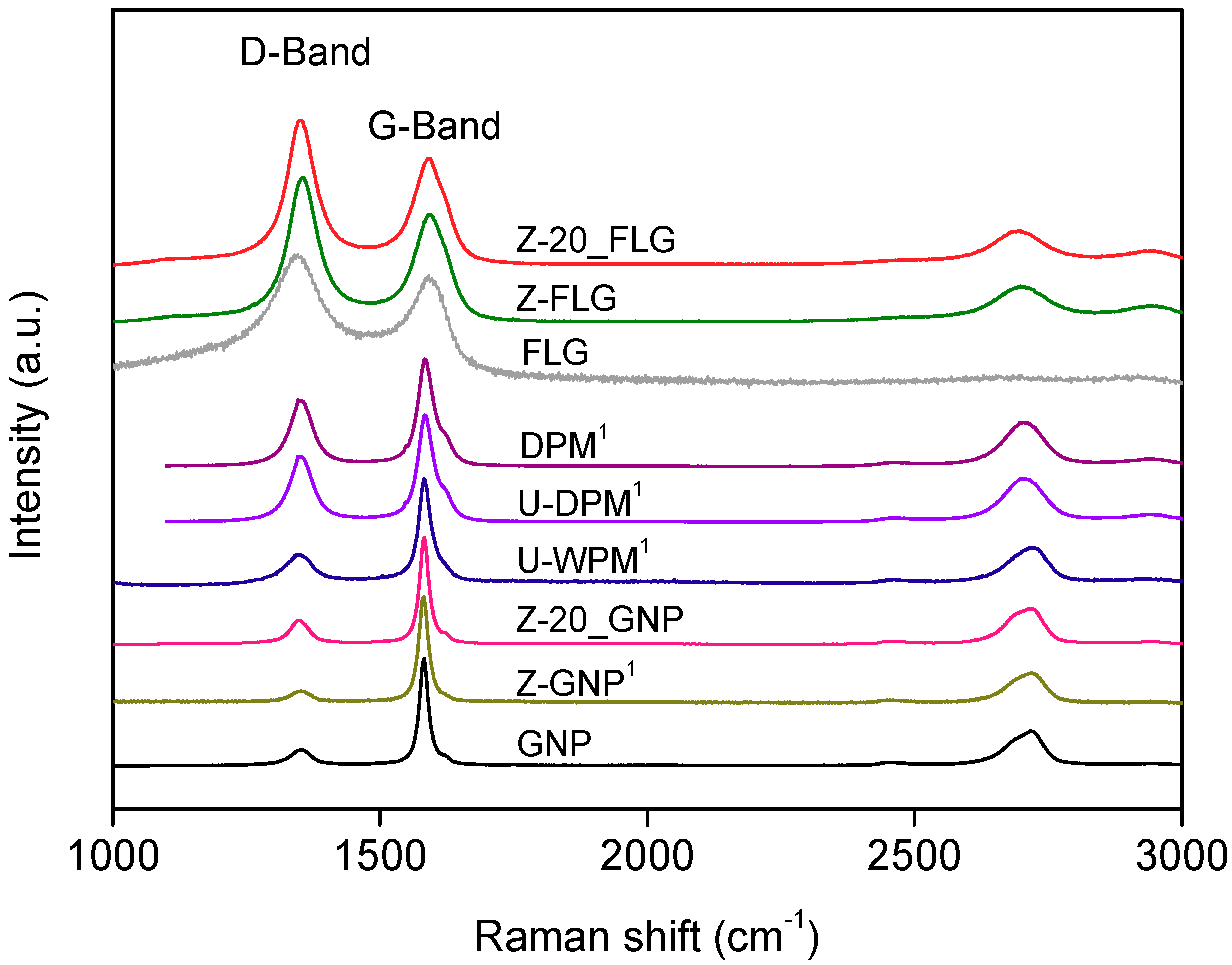
The sintering technique and sintering conditions selected produce mostly dense composites (see Table 1) with undamaged GBNs. This last statement is supported by the Raman spectra from the composites (Figure 1), which possess the characteristic bands for the graphitic structures (G, D, 2D) positioned in the frequencies corresponding to the GBNs. An increase in the ID/IG ratio in the samples subjected to milling in comparison with the as-received GBNs is also observed, which points to the smaller size of the GBNs, confirmed by SEM.
The densification of the 3YTZP/GBN composite powders subjected to the different homogenization routines and sintered with the conditions indicated in the experimental section has been quite successful and is presented in Table 2. The results indicate that the increase in GBN content from 10 to 20 vol% inhibits densification of the composites when the thickness of the GBN is very small. The GNPs used in this study do not inhibit densification, but FLG does. Since all the composites exhibit negligible porosity in the ceramic matrix, the reason for the low density values must rely on the spaces left between the stacked FLG, which have not flat but corrugated surfaces.
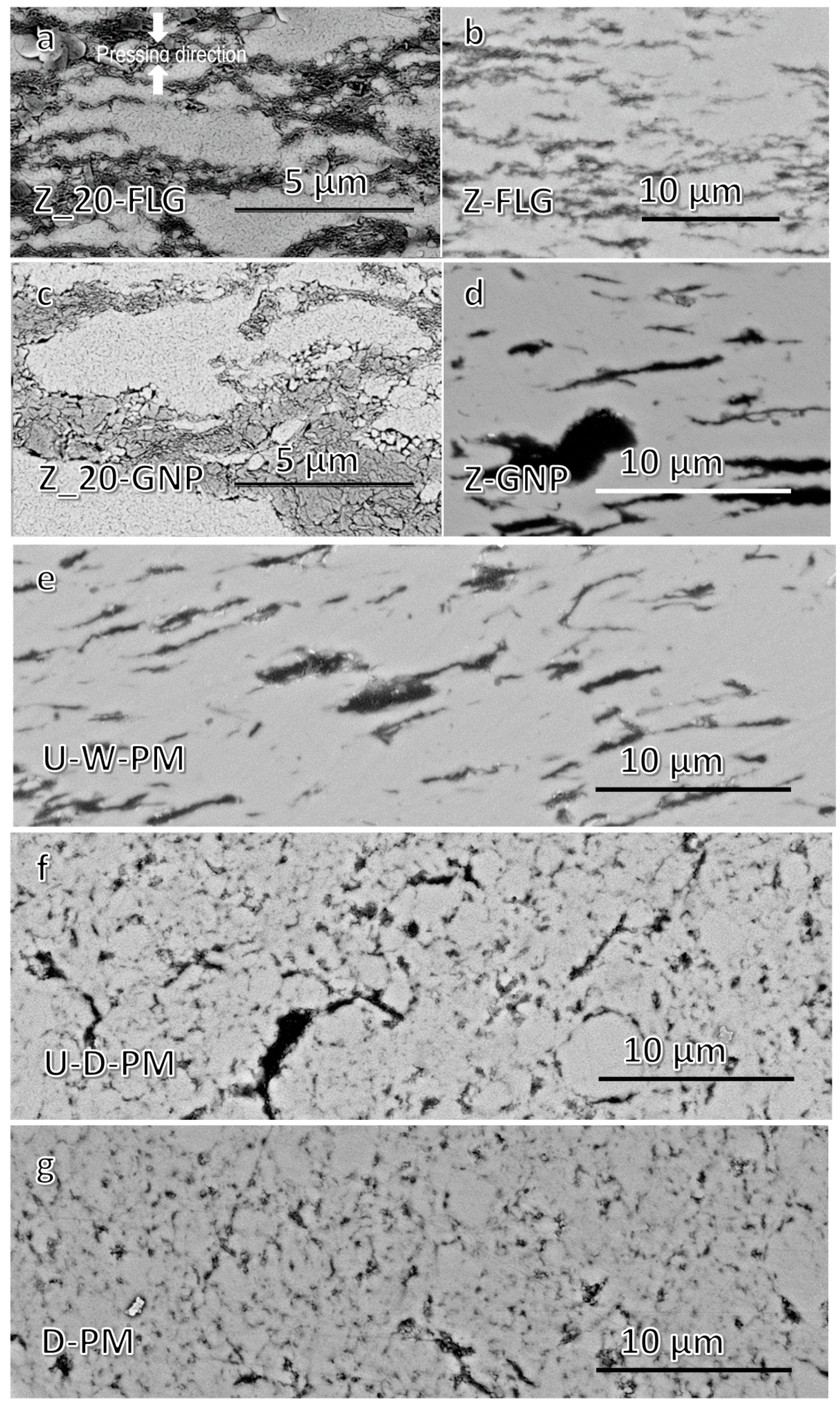
The degree of homogeneity of the composites (and consequently the degree of agglomeration of the GBN used as filler) can be inferred from the SEM images (Figure 2) acquired by backscattered electrons (BSE). The light phase corresponds to the 3YTZP matrix while the dark phase corresponds to the GBNs. If we try to classify the composites according to their structural homogeneity, it can be seen that the composites that have been dry milled (Figure 2f,g) are much more homogeneous, showing a greater amount of ceramic grain boundaries with GNPs. Composites with FLG (Figure 2a,b) are less homogeneous than those with GNPs subjected to dry milling, and more than the composites subjected to wet milling. The composites with ultrasound mixed GNPs and 3YTZP (Figure 2c,d) are the least homogeneous (highest GBN agglomerate size and highest amount of “clean” ceramic grain boundaries). The structural anisotropy due to the high surface area and the preferential orientation of the GBNs are also different in the composites. The composites with GNPs and FLG subjected only to sonication, and also the wet milled composite (Figure 2a–e), show aligned groups of interconnected GBNs in a preferential orientation (perpendicular to the SPS compression axis). The two composites subjected to dry planetary ball milling (Figure 2f,g) show a fairly isotropic microstructure, probably due to the small lateral size of the GNPs achieved by the dry milling.
The 3YTZP ceramic grain size (planar diameter, Table 2) depends on the size and content of the GBN filler in the composite. Both increasing the GBN content and reducing the GBN dimensions decrease the ceramic grain size. This combined effect can be explained by the accepted fact that the GBNs inhibit grain growth [8,25], and by the original fact that this effect is increased with improved homogeneity, which can be favored by reduced GBN dimensions. 
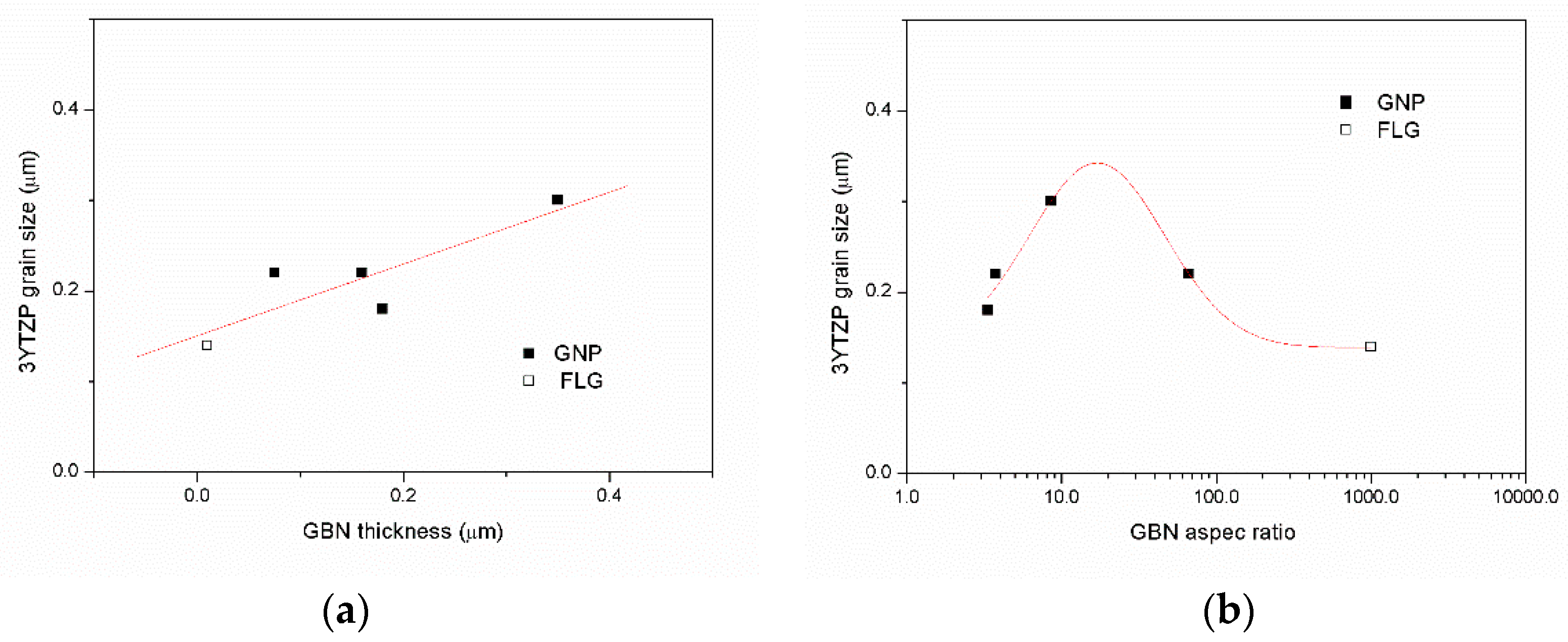
Figure 3 shows the relationship between the 3YTZP grain size and the GBN dimensions ((a) thickness and (b) aspect ratio)) for the 10 vol% GBN content composites. The ceramic grain size increases monotonically with the GBN thickness. Therefore, thinner graphene-based nanostructures with a high aspect ratio are more convenient to get a refined microstructure. However, the values for the ceramic grain size remain in all cases smaller than 0.3 μm.
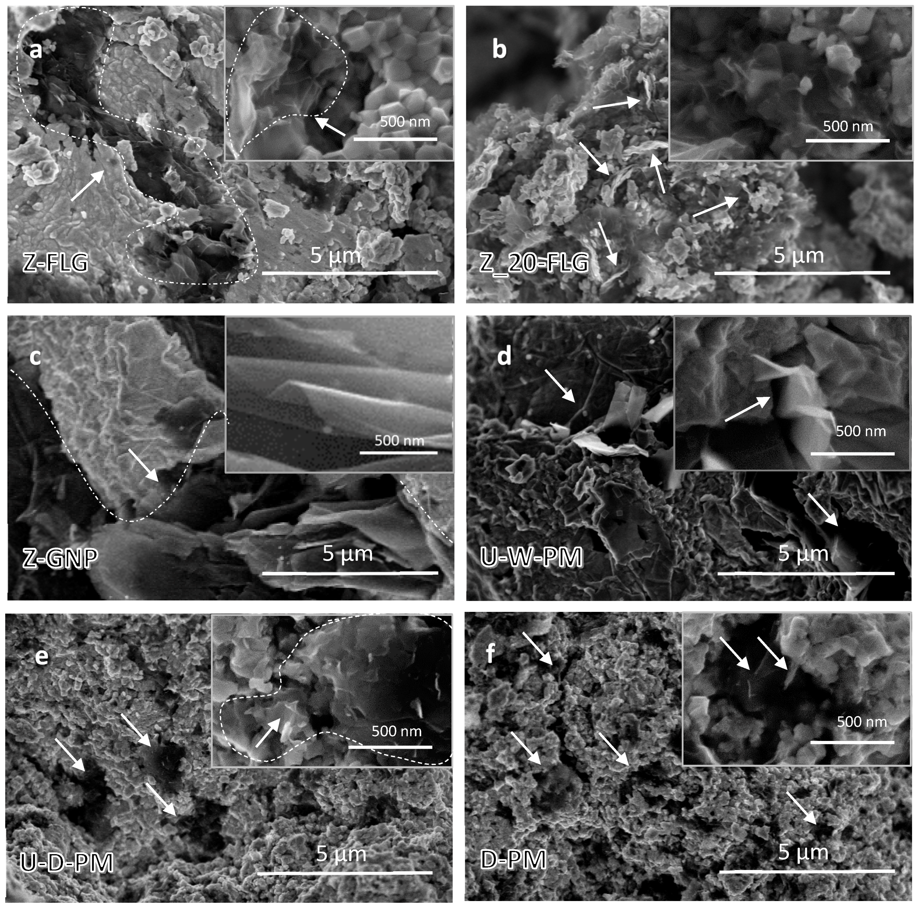
Figure 4 shows the morphology of both the ceramic grains and the GBNs in the fractured surfaces of the different sintered composites, confirming the structural integrity of the GBNs. The FLG, being much thinner than the GNPs, can be observed forming small groups or interconnected structures with few stacked FLG, as the one circled in Figure 4a. The composite with the highest FLG content, Z-20-FLG (Figure 4b), seems to be more homogeneous and the groups of FLG do not appear to be larger than the ones in the composites with 10 vol% FLG. Therefore, no increased agglomeration is observed by increasing the FLG content. The GNPs in the composite Z-GNP—only subjected to ultrasound—are much larger than the ceramic grains and tend to form agglomerates similar to the one in Figure 4c surrounded by a dotted line. The corrugated wavy surfaces of the GNPs (zoomed in the inset) favor the formation of empty spaces between the stacked GNPs. The GNPs subjected to wet milling decrease considerably their size and protrude from the ceramic grains in small stacked aggregates, as can be seen in Figure 4d. Therefore, they could provide a pull-out strengthening mechanism to the composite if the graphene is well bonded to the ceramic matrix, as it happens with alumina matrix composites [26]. The GNPs in the composites subjected to high-energy planetary ball milling are even more reduced in lateral dimensions. They form even smaller aggregates, or groups of interconnected platelets (inset of Figure 4e, corresponding to U-D-PM), and the smallest aggregates are found in the D-PM composite (see Figure 4f)—subject only to dry planetary milling. The homogeneity of these two milled composites is higher than that of the ones prepared using other mixing techniques. Although the composites with FLG are much more homogeneous than the ones with GNPs—both subjected to ultrasonic agitation—the homogeneity of the high-energy planetary milled composites with GNPs is the highest.
The electrical conductivity exhibits higher values when the current flows perpendicular to the sintering compression axis (σ), with most of the GBNs lying with the ab-plane configuration, as observed for different ceramic matrices and filler contents [8,27]. However, the results in Table 2 indicate that the electrical anisotropy decreases slightly with the higher 20 vol% GBN content and abruptly (exhibiting a nearly isotropic behavior) for the composites subjected to high-energy planetary milling. This is due to the fact that the milling drastically reduces the lateral dimensions of the GNPs, which diminish their intrinsic anisotropy and, therefore, also their preferential orientation, as it has been pointed out also by the SEM-BSE observations of the composites’ polished surfaces (Figure 2). The electrical conductivity increases with decreasing GBN size due to the better microstructural homogeneity. The dry milling of the composite powders with low-cost GNPs without ultrasonic probe used in this study has the same effect as using thinner and more expensive FLG in terms of electrical conductivity. The highest conductivity is achieved in composites with the highest content of GBN, either FLG or GNP. For the composites with FLG, the conductivity increases abruptly (a 370% increase) when the filler content rises from 10 to 20 vol%, with a maximum value of σ ~ 2826 Sm−1 in a direction perpendicular to the SPS axis. Similar electrical conductivity values (2800 Sm−1) have been reported in the literature for polymer-derived Si–O–C ceramics synthesized using a gel casting process with the same matrix (YSZ) and 2 wt% FLG [23]. Higher values of electrical conductivity (4000 Sm−1) have been reported for 25 vol% GNP in composites with a Si3N4 matrix [27]. Most composites in our study exhibit similar values of high electrical anisotropy, regardless of the type or content of GBNs. However, dry milling increases the electrical isotropy of the composites from 0.1 to 0.5 when the ultrasound probe is used and it produces isotropic composites when dry milling is the only mixing technique.
The average electrical conductivity of the composites is a useful parameter for evaluating their behavior in applications, such as electro-discharge machining (EDM). It is related to the GBN size, but it depends mainly on the content of the GBN filler. Both increasing GBN content and reducing GBN dimensions increase the electrical conductivity. The major increase in the electrical conductivity with GBN content has already been pointed out by multiple studies in the literature [13,23,27]. However, the increase related to the reduced GBN dimensions obtained in this work can be explained by the improvement in the percolation of the GBN network that takes place when the GBN size decreases and their homogeneous distribution in the ceramic grain boundaries improves. A similar effect has been reported for ceramic composites with carbon nanotubes [28,29]. The increased electrical conductivity and isotropy for the composites prepared with dry milling in the powder processing make them attractive for applications as electron discharge machining (EDM). Although many issues still need to be investigated, such as the effect of the FLG/ceramic mixed powder milling, a deeper microstructural characterization with TEM studies of the GBN/ceramic interfaces and the mechanical characterization of the composites with toughness measurements and fracture propagation studies assessing the viability of EDM on these composites is a most interesting and practical issue.

4. Conclusions

While wet planetary ball milling of 3YTZP-GNP composite powders achieves a significant GNP reduction (40% decrease in the minor diameter, 30% decrease in the lateral size), the dry milling condition is much more effective in reducing the GNP size (70% decrease in thickness and 90% in lateral size). The highest microstructural homogeneity is achieved in sintered composites with GNP dispersed using high energy planetary milling.
The electrical conductivity of the composites increases with GBN content and with the decrease in the GBN dimensions. The latter can be explained by the percolation improvement of the GBN network that takes place when the GBN size decreases and their distribution in the ceramic grain boundaries is more homogeneous.
The electrical anisotropy of the composites decreases abruptly with GBN content and exhibits a nearly isotropic behavior in the 20 vol% GNP/3YTZP composite and also in all the composites subjected to high-energy planetary milling. This is due to the fact that the milling reduces drastically the lateral dimensions of the GNPs, which diminish their intrinsic anisotropy and, therefore, also their preferential orientation.
The highest electrical conductivity is achieved by the composite with 20 vol% FLG, with an average conductivity value σ = 1650 S m−1 and maximum value σ ~ 2826 S m−1.

Author Contributions

Conceptualization: Á.G.-L., A.M.-R., and R.P.; Funding acquisition: Á.G.-L., A.M.-R., and R.P.; Investigation: Á.G.-L., C.L.-P., C.M.-F., C.G.-O., A.M.-R., and R.P.; Methodology: Á.G.-L., A.M.-R., and R.P.; Supervision: Á.G.-L., A.M.-R., and R.P.; Validation: Á.G.-L., A.M.-R., and R.P.; Writing–original draft: Á.G.-L., Writing–review and editing: A.M.-R. and R.P.

Funding

This research was funded by the Ministerio de Economía y Competitividad, and European FEDER fundings, with grant number MAT2015-67889-P.

Acknowledgments

The authors would like to acknowledge the CITIUS (Centros de Investigación, Tecnología e Innovación de la Universidad de Sevilla) for the microanalysis, X-ray diffraction and SEM facilities. Finally, our gratitude to F. Gotor for giving us access to their planetary ball mill in the ICMS (Sevilla).

Conflicts of Interest

The authors declare no conflict of interest. The funders had no role in the design of the study; in the collection, analyses, or interpretation of data; in the writing of the manuscript, and in the decision to publish the results.

References

  1. Ramirez, C.; Miranzo, P.; Belmonte, M.; Isabel Osendi, M.; Poza, P.; Vega-Diaz, S.M.; Terrones, M. Extraordinary toughening enhancement and flexural strength in Si3N4 composites using graphene sheets. J. Eur. Ceram. Soc. 2014, 34, 161–169. [Google Scholar] [CrossRef]
  2. Walker, L.S.; Marotto, V.R.; Rafiee, M.A.; Koratkar, N.; Corral, E.L. Toughening in Graphene Ceramic Composites. ACS Nano 2011, 5, 3182–3190. [Google Scholar] [CrossRef] [PubMed]
  3. Jouault, B.; Jabakhanji, B.; Camara, N.; Desrat, W.; Tiberj, A.; Huntzinger, J.-R.; Consejo, C.; Caboni, A.; Godignon, P.; Kopelevich, Y. Probing the electrical anisotropy of multilayer graphene on the Si face of 6 H-SiC. Phys. Rev. B 2010, 82, 85438. [Google Scholar] [CrossRef]
  4. Miranzo, P.; Ramirez, C.; Roman-Manso, B.; Garzon, L.; Gutierrez, H.R.; Terrones, M.; Ocal, C.; Isabel Osendi, M.; Belmonte, M. In situ processing of electrically conducting graphene/SiC nanocomposites. J. Eur. Ceram. Soc. 2013, 33, 1665–1674. [Google Scholar] [CrossRef]
  5. Li, M.; Liu, Q.; Jia, Z.; Xu, X.; Cheng, Y.; Zheng, Y.; Xi, T.; Wei, S. Graphene oxide/hydroxyapatite composite coatings fabricated by electrophoretic nanotechnology for biological applications. Carbon 2014, 67, 185–197. [Google Scholar] [CrossRef]
  6. Lee, B.; Koo, M.Y.; Jin, S.H.; Kim, K.T.; Hong, S.H. Simultaneous strengthening and toughening of reduced graphene oxide/alumina composites fabricated by molecular-level mixing process. Carbon 2014, 78, 212–219. [Google Scholar] [CrossRef]
  7. Centeno, A.; Rocha, V.G.G.; Alonso, B.; Fernández, A.; Gutierrez-Gonzalez, C.F.F.; Torrecillas, R.; Zurutuza, A. Graphene for tough and electroconductive alumina ceramics. J. Eur. Ceram. Soc. 2013, 33, 3201–3210. [Google Scholar] [CrossRef] [Green Version]
  8. Gallardo-López, A.; Márquez-Abril, I.; Morales-Rodríguez, A.; Muñoz, A.; Poyato, R. Dense Graphene Nanoplatelet/Yttria Tetragonal Zirconia Composites: Processing, Hardness and Electrical Conductivity. Ceram. Int. 2017, 43, 11743–11752. [Google Scholar] [CrossRef]
  9. Li, S.; Xie, Z.; Zhang, Y.; Zhou, Y. Enhanced toughness of zirconia ceramics with graphene platelets consolidated by spark plasma sintering. Int. J. Appl. Ceram. Technol. 2017, 14, 1062–1068. [Google Scholar] [CrossRef]
  10. Bianco, A.; Cheng, H.-M.; Enoki, T.; Gogotsi, Y.; Hurt, R.H.; Koratkar, N.; Kyotani, T.; Monthioux, M.; Park, C.R.; Tascon, J.M.D.; et al. All in the graphene family—A recommended nomenclature for two-dimensional carbon materials. Carbon 2013, 65, 1–6. [Google Scholar] [CrossRef]
  11. Inam, F.; Vo, T.; Bhat, B.R. Structural stability studies of graphene in sintered ceramic nanocomposites. Ceram. Int. 2014, 40, 16227–16233. [Google Scholar] [CrossRef]
  12. Román-Manso, B.; Domingues, E.; Figueiredo, F.M.; Belmonte, M.; Miranzo, P. Enhanced electrical conductivity of silicon carbide ceramics by addition of graphene nanoplatelets. J. Eur. Ceram. Soc. 2015, 35, 2723–2731. [Google Scholar] [CrossRef]
  13. Poyato, R.; Osuna, J.; Morales-Rodríguez, A.; Gallardo-López, Á.; Gallardo-López, A. Electrical conduction mechanisms in graphene nanoplatelet/yttria tetragonal zirconia composites. Ceram. Int. 2018, 44, 14610–14616. [Google Scholar] [CrossRef]
  14. Rudolf, C.; Boesl, B.; Agarwal, A. In situ indentation behavior of bulk multi-layer graphene flakes with respect to orientation. Carbon 2015, 94, 872–878. [Google Scholar] [CrossRef]
  15. Shin, J.-H.; Hong, S.-H. Fabrication and properties of reduced graphene oxide reinforced yttria-stabilized zirconia composite ceramics. J. Eur. Ceram. Soc. 2014, 34, 1297–1302. [Google Scholar] [CrossRef]
  16. Ramirez, C.; Garzon, L.; Miranzo, P.; Osendi, M.I.; Ocal, C. Electrical conductivity maps in graphene nanoplatelet/silicon nitride composites using conducting scanning force microscopy. Carbon 2011, 49, 3873–3880. [Google Scholar] [CrossRef]
  17. Singh, V.; Joung, D.; Zhai, L.; Das, S.; Khondaker, S.I.; Seal, S. Graphene based materials: Past, present and future. Prog. Mater. Sci. 2011, 56, 1178–1271. [Google Scholar] [CrossRef]
  18. Michalkova, M.; Kasiarova, M.; Tatarko, P.; Dusza, J.J.; Sajgalik, P.; Michálková, M.; Kašiarová, M.; Tatarko, P.; Dusza, J.J.; Šajgalík, P. Effect of homogenization treatment on the fracture behaviour of silicon nitride/graphene nanoplatelets composites. J. Eur. Ceram. Soc. 2014, 34, 3291–3299. [Google Scholar] [CrossRef]
  19. Candelario, V.M.; Moreno, R.; Guiberteau, F.; Ortiz, A.L. Fabricating eco-friendly nanocomposites of SiC with morphologically-different nano-carbonaceous phases. J. Eur. Ceram. Soc. 2018, 38, 3735–3741. [Google Scholar] [CrossRef]
  20. Klimczyk, P.; Jaworska, L.; Putyra, P.; Pędzich, Z.; Laszkiewicz-Łukasik, J. Effect of Milling Parameters on Microstructure and Selected Mechanical Properties of Si3N4–Graphene Composites. In Key Engineering Material; Trans Tech Publications: Zürich, Switzerland, 2015; Volume 655, pp. 17–21. [Google Scholar]
  21. Chen, F.; Jin, D.; Tyeb, K.; Wang, B.; Han, Y.-H.; Kim, S.; Schoenung, J.M.; Shen, Q.; Zhang, L. Field assisted sintering of graphene reinforced zirconia ceramics. Ceram. Int. 2015, 41, 6113–6116. [Google Scholar] [CrossRef]
  22. Ramirez, C.; Isabel Osendi, M. Characterization of graphene nanoplatelets-Si3N4 composites by Raman spectroscopy. J. Eur. Ceram. Soc. 2013, 33, 471–477. [Google Scholar] [CrossRef]
  23. Markandan, K.; Chin, J.K.; Tan, M.T.T. Enhancing Electroconductivity of Yytria-Stabilised Zirconia Ceramic Using Graphene Platlets. In Key Engineering Materials; Trans Tech Publications: Zürich, Switzerland, 2016; Volume 690, pp. 1–5. [Google Scholar]
  24. López-Pernía, C.; Muñoz-Ferreiro, C.; González-Orellana, C.; Morales-Rodríguez, A.; Gallardo-López, Á.; Poyato, R. Optimizing the homogenization technique for graphene nanoplatelet/yttria tetragonal zirconia composites: Influence on the microstructure and the electrical conductivity. J. Alloy. Compd. 2018, 767, 994–1002. [Google Scholar] [CrossRef]
  25. Vu, D.-T.; Han, Y.-H.; Chen, F.; Jin, D.; Schoenung, J.M.; Lee, D.-Y. Graphene Nano-Platelets Reinforced ZrO2 Consolidated by Spark Plasma Sintering. Sci. Adv. Mater. 2016, 8, 312–317. [Google Scholar] [CrossRef]
  26. Ahmad, I.; Islam, M.; Alharthi, N.H.; Alawadhi, H.; Subhani, T.; Munir, K.S.; Shah, S.I.; Inam, F.; Zhu, Y. Chemical and structural analyses of the graphene nanosheet/alumina ceramic interfacial region in rapidly consolidated ceramic nanocomposites. J. Compos. Mater. 2017, 52, 417–428. [Google Scholar] [CrossRef]
  27. Ramirez, C.; Figueiredo, F.M.; Miranzo, P.; Poza, P.; Osendi, M.I.; Isabel Osendi, M. Graphene nanoplatelet/silicon nitride composites with high electrical conductivity. Carbon 2012, 50, 3607–3615. [Google Scholar] [CrossRef]
  28. Gallardo-López, A.; Morales-Rodríguez, A.; Vega-Padillo, J.; Poyato, R.; Muñoz, A.; Domínguez-Rodríguez, A. Enhanced carbon nanotube dispersion in 3YTZP/SWNTs composites and its effect on room temperature mechanical and electrical properties. J. Alloy. Compd. 2016, 682, 70–79. [Google Scholar] [CrossRef]
  29. Poyato, R.; Macías-Delgado, J.; Gallardo-López, A.; Muñoz, A.; Domínguez-Rodríguez, A. Microstructure and impedance spectroscopy of 3YTZP/SWNT ceramic nanocomposites. Ceram. Int. 2015, 41, 12861–12868. [Google Scholar] [CrossRef] [Green Version]
Figure 1. Raman spectra of the sintered composites listed in Table 2. The spectra of the as-received graphene-based nanostructures (GBNs), namely graphene nanoplatelets (GNPs) and few-layer graphene (FLG) are included for comparison. 1 Data from [24].
Ceramics 01 00014 g001
Figure 2. SEM micrograph with backscattered electrons (BSE) of polished cross-sections of the different composites to illustrate the homogenization degree in composites (a) Z-20_FLG, (b) Z-FLG, (c) Z-20_GNP, (d) Z-GNP, (e) U-W-PM, (f) U-D-PM and (g) D-PM with processing parameters as indicated in Table 1. (a,c) have 20 vol% GBN while the rest of the composites have only 10 vol%. The sintering compression axis is common to all the micrographs and has been indicated in (a).
Ceramics 01 00014 g002
Figure 3. Relationship between the 3YTZP ceramic grain size and the GBN filler dimensions: (a) GBN thickness and (b) GBN aspect ratio.
Ceramics 01 00014 g003
Figure 4. SEM micrographs of the fractured surfaces of the different composites in Table 1, showing the morphology of the ceramic grains and the GBNs to illustrate the effect of the processing route in (a) Z-FLG, (b) Z-20-FLG, (c) Z-GNP, (d) U-W-PM, (e) U-D-PM, and (f) D-PM. The inserts show areas in higher magnification.
Ceramics 01 00014 g004
Table 1. Morphological parameters (major–minor axes) of the as-received graphene-based nanostructures (GBNs) and of the graphene nanoplatelets (GNPs) in the sintered composites with 10 vol% GNP.
FillerMaterialMixing RoutinesGBN Morphology
UltrasoundMillingDmajor (µm)Dmin (µm)
FLGAs-received FLG ≤10 *0.01 *
GNPAs-received GNP ≤5 *0.05–0.1 *
Z-GNPYesNo≤4.30.2–1.0
U-W-PMYesWet≤30.14–0.56
U-D-PMYesDry≤0.60.07–0.25
D-PMNoDry≤0.60.10–0.26
* Data from the supplier.
Table 2. Data corresponding to all the composites fabricated in this study, with 10 and 20 vol% GBN nominal content and processed with the different mixing techniques schematized in Table 1: measured GBN content, relative density, ceramic grain size, electrical conductivity averaged for the two main directions with respect to the sintering axis, and σ// ratio.
SampleMeasured GBN Content (vol%)ρrelative
(%)
dplanar ± s.d.
(µm)
σ
(S·m−1)
σ//
(0–1)
Z-FLG8.72 ± 0.17980.14 ± 0.06440 ± 200.1
Z-20_FLG21.37 ± 0.18950.18 ± 0.091650 ± 700.2
Z-GNP8.96 ± 0.0899.70.22 ± 0.10128 ± 60.1
Z-20_GNP23.4 ± 0.71000.14 ± 0.061485 ± 600.2
U-W-PM8.93 ± 0.0698.40.30 ± 0.1245 ± 40.1
U-D-PM12.77 ± 0.1599.40.22 ± 0.10230 ± 800.5
D-PM9.18 ± 0.1695.90.18 ± 0.07440 ± 300.9

