Radial-Concentric Freeze Casting Inspired by Porcupine Fish Spines


1
Materials Science and Engineering Program, University of California San Diego, La Jolla, CA 92093-0418, USA
2
Department of Structural Engineering, University of California San Diego, La Jolla, CA 92093-0085, USA
3
Department of Mechanical and Aerospace Engineering, University of California San Diego, La Jolla, CA 92093-0411, USA
*
Author to whom correspondence should be addressed.
†
Both authors contributed equally to this work.
Ceramics 2019, 2(1), 161-179; https://0-doi-org.brum.beds.ac.uk/10.3390/ceramics2010015
Submission received: 30 January 2019
/
Revised: 28 February 2019
/
Accepted: 1 March 2019
/
Published: 6 March 2019
(This article belongs to the Special Issue Ice-Templated and Freeze-Cast Ceramics)
Abstract
:Freeze casting is a technique used to manufacture porous ceramics with aligned microstructures. In conventional freeze casting, these microstructures are aligned along a single direction of freezing. However, a caveat to these ceramics has been their ensuing lack of strength and toughness due to their high porosity, especially in the direction orthogonal to the direction of alignment. In this work, a novel freezing casting method referred to as “radial-concentric freeze casting” is presented, which takes its inspiration from the radially and concentrically aligned structure of the defensive spines of the porcupine fish. The method builds off the radial freeze casting method, in which the microstructure is aligned radially, and imposes a concentric alignment. Axial compression and Brazilian tests were performed to obtain axial compressive strengths, axial compressive moduli, and splitting tensile strengths of freeze cast samples with and without epoxy infiltration. Notably, radial-concentric freeze cast samples had the greatest improvements in axial compressive modulus and splitting tensile strength with infiltration, when compared against the changes in mechanical properties of conventional and radial freeze cast ceramics with infiltration. These results provide further evidence for the importance of structure in multiphase materials and the possibility of enhancing mechanical properties through the controlled alignment of microstructures.
1. Introduction
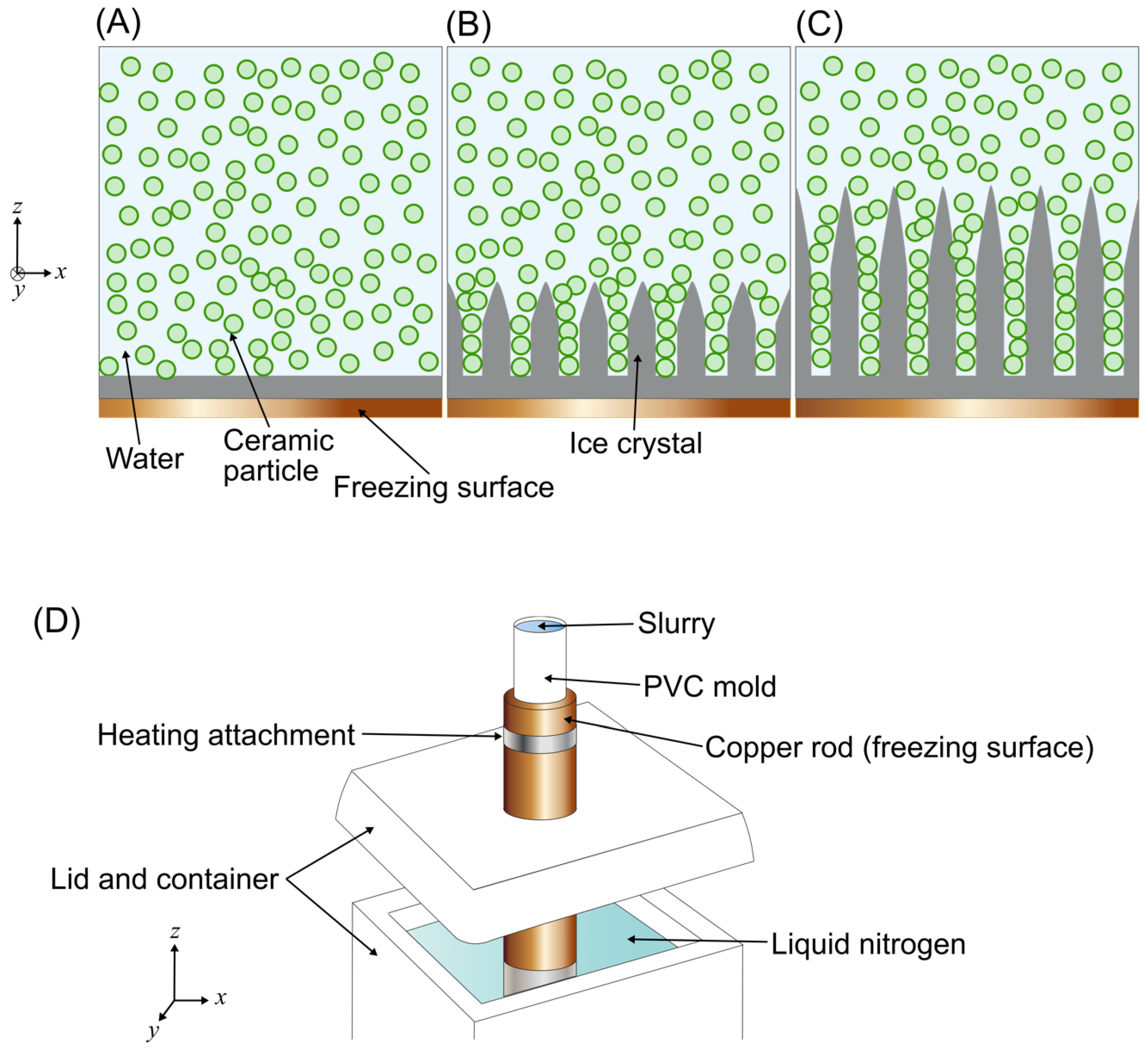
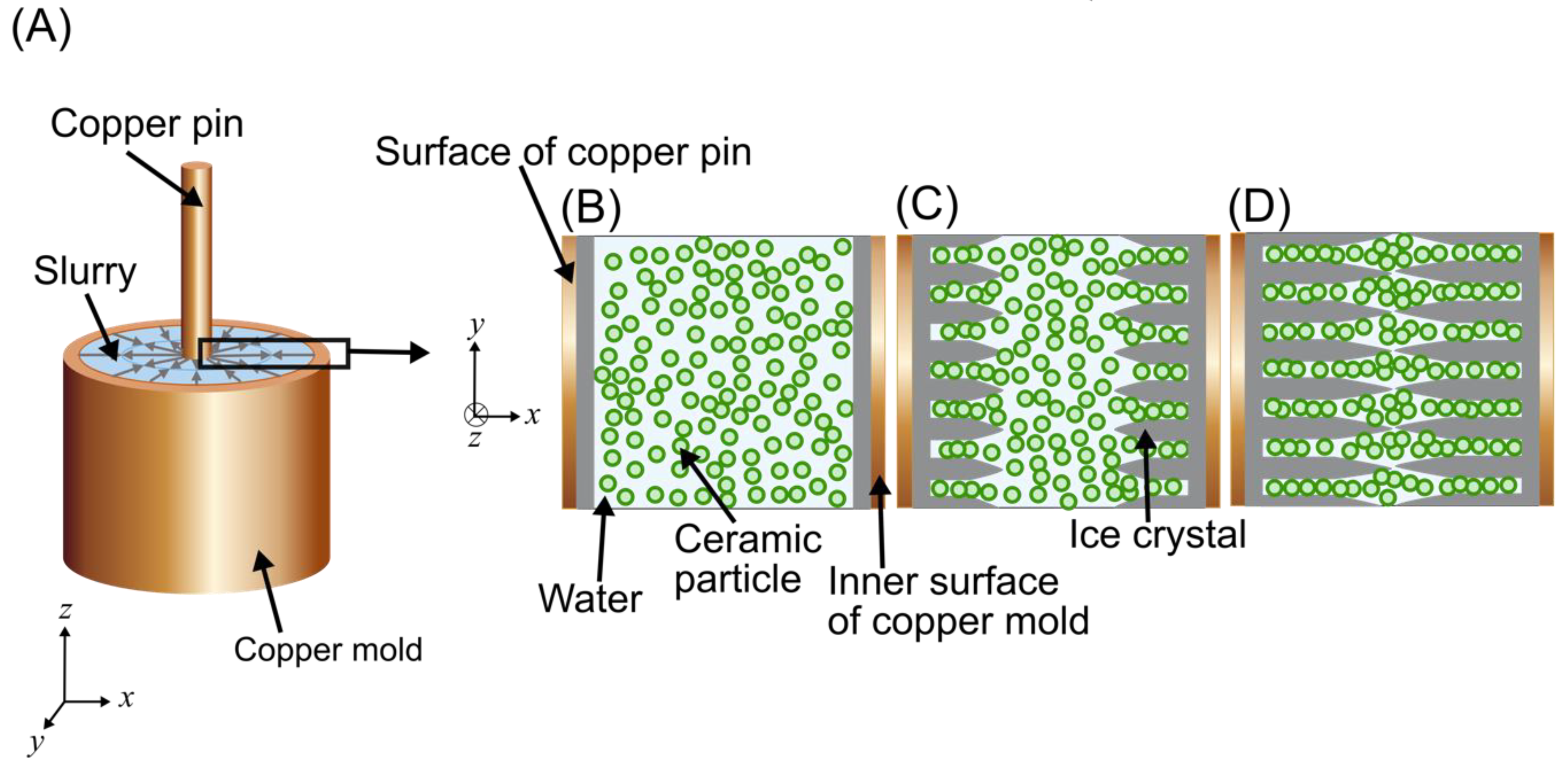
Freeze casting was introduced as early as the mid-20th century for technical applications requiring the use of refractory materials. The method uses the directional freezing of a colloidal suspension to produce a material with a controlled microstructure. As solvent crystals grow from one end of a suspension to another, particles become packed in between individual crystal arms, as shown in Figure 1. Then, the solvent is removed through lyophilizing (freeze-drying) so that a scaffold with a porous, aligned microstructure remains.
Its benefit as a “near-net-shape” processing method originally made it a candidate for the manufacturing of parts with complex curvatures such as turbine blades [1]. The flexibility of the freeze casting method quickly expanded in research scope. To date, freeze casting has been used to manufacture a variety of cellular materials, including metallic foams [2,3,4,5], nanowhisker scaffolds [6,7,8,9], graphene monoliths [10], and ceramic substrates for the aquaculture of coral [11]. In addition, freeze casting has potential applications in solid oxide fuel cells [12] as well as biomaterials [13], where interconnected channels can allow for the proliferation of cells, and one may choose to cast materials that are biocompatible or bioactive. Therefore, others have focused on the freeze casting of porous scaffolds using biomedical grade ceramics such as hydroxyapatite [14,15,16,17,18], alumina [19], and zirconia [20]. However, a continuing issue with these scaffolds is their ensuing lack of strength and toughness due to their high porosity.
Some researchers have used bioinspiration to improve the mechanical properties of freeze cast ceramics. A dense ceramic inspired by abalone nacre, using a slurry of alumina platelets mixed with alumina nanoparticles to create a ceramic material with high strength, toughness, compressive modulus, and thermal stability, was manufactured by Bouville et al. [21]. Inspired by the narwhal tusk, Porter et al. [22,23] used a rotating magnetic field to align magnetized ceramic particles during freezing; the resulting spiraling ceramic scaffold showed greater strength and stiffness in the direction of the magnetic field. Likewise, a magnetic field was used to align magnetized alumina particles during freeze casting; the resulting microstructures mimicked the aligned pores of spongy bone [24].
The development of bioinspired materials also aids in the understanding of structures present in natural materials that are not common in engineering designs. Since biological materials are often complex composites that vary greatly in form and composition, even within the same specimen, understanding the effects of a structural feature in a biological material on its various mechanical properties, and therefore the design’s purpose, can be difficult. By creating bioinspired materials in which different microstructures can be produced with the same composition, the effects of these microstructures on mechanical properties can be properly compared.
1.1. Microstructural Control in Freeze Casting for Bioinspired Materials
In what is here considered “conventional” freeze casting, the freezing process begins when cooling is applied to one end of a colloidal suspension of particles, called the slurry, and a planar freezing front (the advancing interface between solidified solvent crystals and liquid suspension) forms, as in Figure 1A. The term “conventional” is used to describe the most common and simple freeze casting setup that results in directional porosity. As the freezing front progresses, particles in the suspension can be rejected or engulfed by the solidifying solvent [25,26]. Whether or not particles are engulfed or rejected depends on what configuration is favored by the interfacial free energy (between particle-solid, particle-liquid, and liquid-solid) [25]. Instability in the planar freezing front instigates a transition to dendritic growth of the solvent crystals, as in Figure 1B. Peppin et al. [27,28], showed through a linear stability analysis and experiments that constitutional supercooling in the liquid suspension ahead of the freezing front can cause such an instability. Then, freezing proceeds with the solvent crystals aligning themselves parallel to the thermal gradient imposed in the suspension [29]. Particles are rearranged and “packed” in between the solvent crystals, as in Figure 1C.
In conventional freeze casting setups (see Figure 1D), the slurry is contained in a non-conductive cylindrical mold (usually polyvinyl chloride, or PVC) positioned on top of a copper rod. Cooling is applied by immersing the bottom of the copper rod in liquid nitrogen. The top surface of the copper rod, which is in contact with the slurry, acts as a “freezing surface.” This freezing surface imposes a vertically aligned temperature gradient throughout the slurry so that growing solvent crystals are aligned longitudinally. Once the sample is completely frozen, the solvent phase is removed through freeze drying, and the resulting porous ceramic structure is typically held together by remaining polymer binder. The sample can be processed further through sintering, infiltration with a polymer, or sintering and subsequent polymer infiltration.
Through freeze casting, one may specify the pore shape, pore size, and microstructural alignment of the ceramic by controlling the growth of solvent crystals during freezing. Microstructural control of the freeze cast ceramic can be achieved through “intrinsic” and “extrinsic” methods [30]. Intrinsic methods change the inherent freezing characteristics of the slurry and can include the choice of solvent, additives to the slurry, and choice of particle. For example, freeze casting a slurry of alumina particles in camphene results in a scaffold with rounded pores [26,31,32,33,34]. Meanwhile, freeze casting a slurry of alumina particles in water results in a scaffold with lamellar pores [35,36,37,38]. Extrinsic methods impose outside forces or parameters to affect the freezing process [30]. Examples of extrinsic methods of control include the magnetic freeze casting procedure [22,23,24] and a double freeze casting procedure, in which a freeze cast scaffold with one direction of alignment is infiltrated with slurry and freeze cast a second time orthogonal to the first direction of alignment, that results in a scaffold with an interpenetrating “grid-like” structure with two directions of alignment [31,39,40]. Another extrinsic freeze casting method is “two-step freeze casting”, where slurry is poured around a conventionally freeze cast scaffold that has not been lyophilized and the whole sample is freeze cast a second time; in this method, melting and refreezing of the first freeze cast scaffold was seen to create a blended interface between it and the portion of freeze cast scaffold from the second step [41].
In this study, a novel bioinspired freeze casting method was developed, which builds off the extrinsic method hereafter referred to as “radial freeze casting.” Moon et al. [12] first developed a form of radial freeze casting using a metal cylindrical mold as the freezing surface so that resulting scaffolds were radially aligned. Later, an altered conventional freeze casting setup (of the kind shown in Figure 1) was developed by using a copper mold in lieu of a PVC mold [42]. Thus, the bottom freezing surface imparted cooling to the copper mold so that the mold acted as a second freezing surface. The microstructures of the resulting ceramic scaffolds were both longitudinally and radially aligned. The method described in this paper, which will be referred to as “radial-concentric freeze casting,” uses radial freeze casting to create longitudinally and radially aligned structures. In addition, through a two-step process, it introduces concentric structures. First, a radial freeze cast is performed similarly to what is done in [42], with the exception of a copper pin placed in the center of the copper mold. Second, the copper pin is removed from the frozen solid, the void left by the pin is filled with more slurry, and a second freeze cast is performed. This step in the radial-concentric freeze casting method is similar to the two-step freeze casting method previously described [41]; however, it differs from two-step freeze casting in that the temperatures of the freeze cast solid and additional slurry are first equilibrated to prevent partial melting-recrystallization. The morphology of the layers arising from each step and the interfaces between them are explored in this paper.
1.2. Bioinspiration from the Porcupine Fish Spine
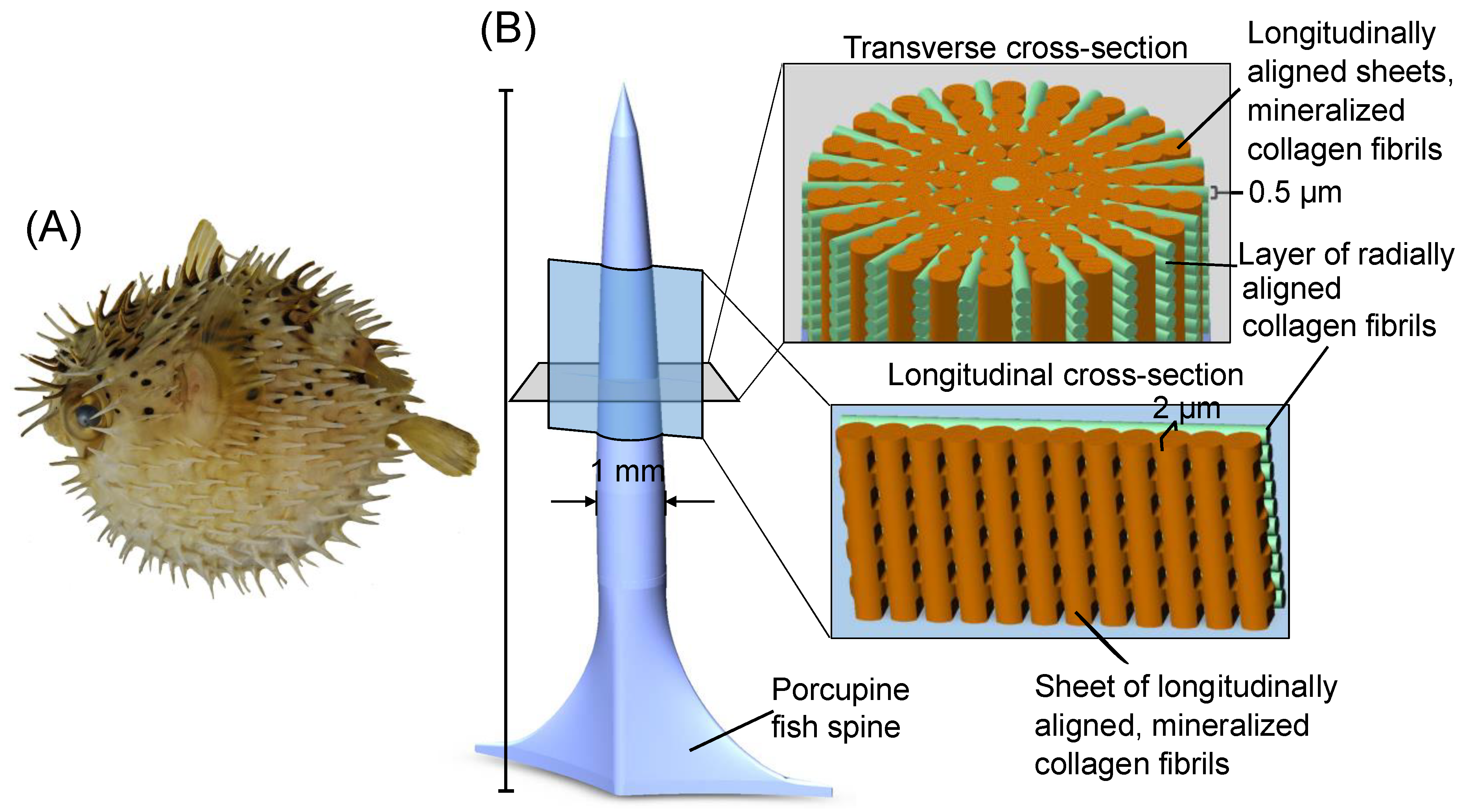
This novel freeze casting method was inspired by the defensive spines of the porcupine fish, members of the family Diodontidae, which are found throughout most oceans in temperate environments [43]. Like the pufferfish, porcupine fish can inflate to approximately three times their initial volume by filling their stomachs with water or air; it is hypothesized that they do so to become too large for a predator to swallow [44]. However, porcupine fish also have an added layer of defense—modified scales in the form of stiff, sharp spines covering the body that orient outward when the fish inflates. One may infer that these spines must be strong enough to protect against a predator’s bite. Meanwhile, the hundreds of spines covering the fish’s body [45] must be lightweight enough for the fish to maintain neutral buoyancy.
In previous work, the defensive spines of the species Diodon holocanthus and Diodon hystrix were characterized [45]. The porcupine fish spine is composed of a combination of hydroxyapatite and collagen [45], similar to other fish scales [46]. It was shown that the hydroxyapatite and collagen phases form a concentric and radial alignment, as shown in Figure 2 [45]. Mechanical tests showed both transverse stiffness and strength many times greater than that of similarly composed biological materials [45,46]. The authors of [45] posited that these mechanical property improvements arise from the radial and concentric alignment of the hydroxyapatite and collagen phases. This hypothesis has precedent from the literature, such as ceramics of alternating layers of dense and porous SiC [47] and CeZrO2/Al2O3 [48] layered ceramics fabricated through slip casting.
Inspired by the defensive spines of Diodon holocanthus, the radial-concentric freeze casting method was developed to align the ceramic scaffold’s microstructure both radially and concentrically. Microstructures of the radial-concentric freeze cast ceramics were characterized using scanning electron microscopy (SEM) and compared to those of both conventional and radial freeze cast ceramics. Finally, axial (longitudinal direction parallel to the bottom freezing surface) compression and Brazilian tests on conventional, radial, and radial-concentric freeze cast samples were performed to explore the differences in mechanical properties between freeze cast ceramics with and without a bioinspired radial-concentric structure.
2. Materials and Methods
2.1. Freeze Casting
Ceramic slurries of 30 vol.% were made using alumina (Al2O3) powder (SM8, Baikowski, Charlotte, NC, USA) with a particle size of 300 nm as the solute and deionized water as the solvent. Water was chosen as a solvent so that ice crystals would form lamellar pores resembling the radially aligned hydroxyapatite phases of the porcupine fish spine. A binder of 1 wt.% polyethylene glycol (PEG 400, Alfa Aesar, Ward Hill, MA, USA) and a dispersant of 1 wt.% sodium polyacrylate solution (Darvan 811, Vanderbilt Minerals, LLC, Norwalk, CT, USA) were used. The Al2O3 powder was mixed with the binder and dispersant in deionized water and ball-milled for 24 h. The ball-milled slurry was then degassed in a desiccator for 20 min and freeze cast at a cooling rate of −10 °C per min from 10 °C to −170 °C.
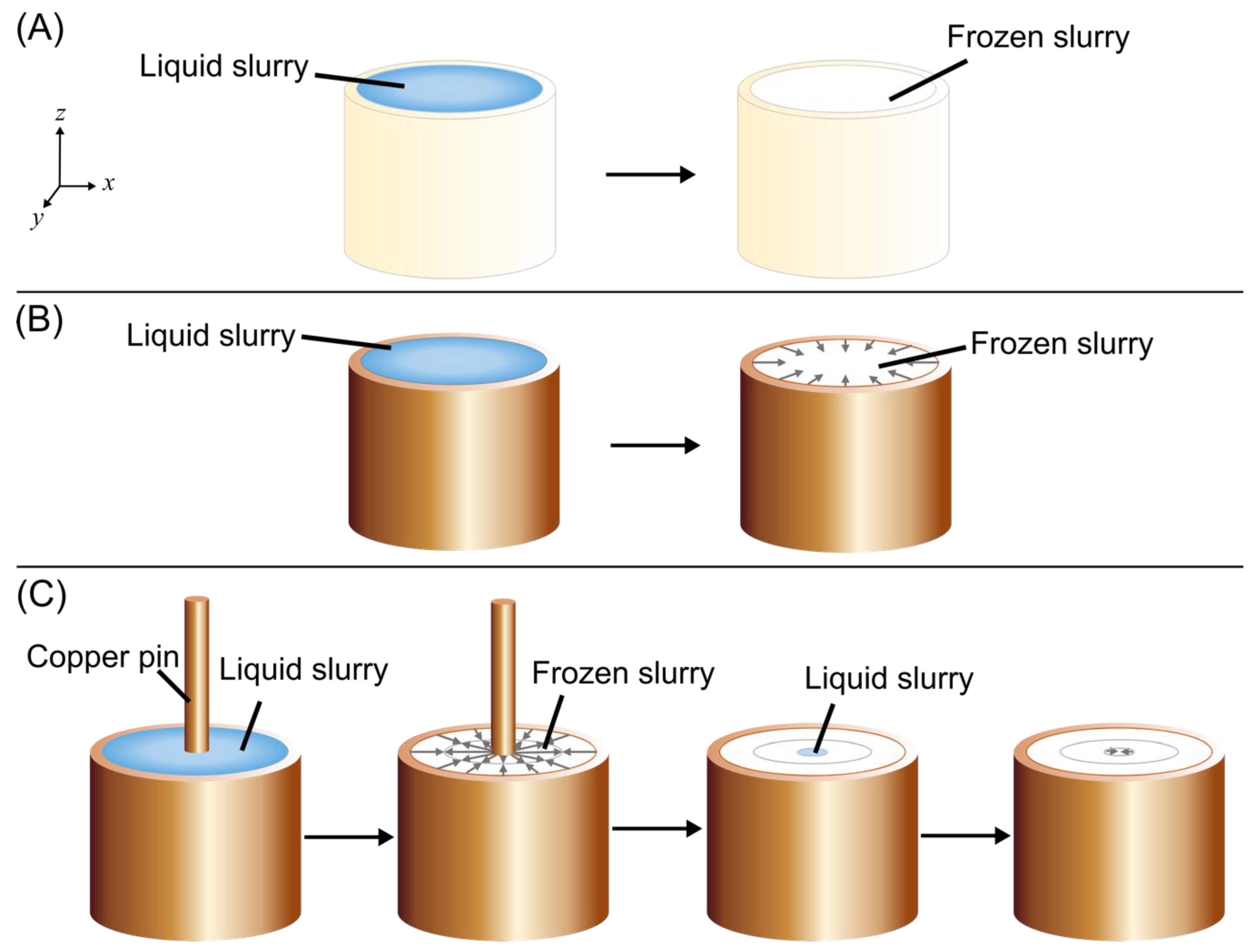
Conventional, radial, and radial-concentric freeze cast samples were prepared (see Figure 3A–C) and the resulting structures of each method were compared. A summary of samples manufactured and mechanically tested can be found in Tables S1–S3. For conventional freeze cast samples (Figure 3A), a cylindrical PVC mold with an inner diameter of 17.4 mm was used so that freezing started from the base of the sample; ice crystals then grew vertically upwards and were aligned longitudinally. For radially freeze cast samples (Figure 3B), a cylindrical copper mold of 17.4 mm inner diameter was used so that there were two origins of freezing: one at the base and another from the edges of the mold, resulting in both longitudinally and radially aligned porosity. For radial-concentric samples (Figure 3C), concentric rings were created in two steps. First, the sample was radially freeze cast using a copper mold and a 4.75 mm diameter copper pin placed in the center of the mold. Thus, freezing originated from three surfaces: the base, the surface of the outer copper mold, and the surface of the pin. Radially aligned ice crystals grew both inward from the mold and outward from the pin. These ice crystals then met halfway between each other to form an interface. In the second step, the pin was removed, slurry was poured into the resulting cavity of the freeze cast solid, and the sample was freeze cast again to form the center of the sample with radial alignment; thus, a second interface was formed between this center and the freeze cast solid from the first step. Prior to pouring the slurry into the cavity, the temperatures of the freeze cast solid and the slurry were equilibrated through thawing of the freeze cast solid and cooling of the slurry. The solid was thawed to a temperature between −5–0 °C, with temperature measured by contact of the top surface of the solid with a thermocouple, to lessen its effect as an unintended freezing surface. The slurry was cooled to a temperature between 0–5 °C by partially submerging the slurry container in liquid nitrogen, with the temperature again measured using a thermocouple, so that it would not melt the solid as it was poured in. Neglecting to equilibrate the temperatures of the freeze cast solid and slurry resulted in multiple unevenly spaced rings radiating from the center (Figure S1).
Samples were then freeze dried (Labconco, Kansas City, MO, USA) at −50 °C and 3.5 × 10⁻⁶ Pa. Samples were sintered in an open-air furnace for three hours at 1500 °C, with heating and cooling rates of 2 °C/min. Samples were 14 mm in diameter (shrinkage of sample diameters was a result of sintering). Approximately 1.5 cm of the bottom portions of samples were removed, and samples were cut to ≈14 mm in length.
Additionally, a separate set of samples were infiltrated with epoxy (EpoxiCure 2 Epoxy System, Buehler, Lake Bluff, IL, USA). Samples were immersed completely in epoxy and degassed for 30 min. Samples were then removed from the epoxy and allowed to cure overnight.
2.2. Microstructural Characterization
Microstructures of radial and radial-concentric samples were imaged using an environmental SEM (FEI/Philips XL-30, FEI, Hillsboro, OR, USA). To prepare samples for SEM, the finished ceramic sample (of 14 mm in height) was cut using a rotary saw so that approximately 4 mm from the top and bottom ends were removed. Then, cut surfaces were polished using 90 grit and 600 grit sandpaper. Samples were fixed to a sample stub using carbon tape and carbon paint and sputter coated with iridium (Emitech K575X, Quorum Technologies Ltd., East Sussex, UK) for 15 s at 85 mA. Samples were imaged under 10 kV accelerating voltage. Full axial cross sections of conventional, radial, and radial-concentric freeze cast samples were made by stitching together individual SEM images to create a composite image.
Porosity of scaffolds () was calculated using the bulk density of alumina ( 3.95 g/cm3) and the relative density ( of mechanical testing scaffolds, which is calculated from measured mass (m) and volume (V). This calculation is shown in Equation (1):
2.3. Mechanical Testing
The cylindrical freeze cast samples were tested in axial compression and analyzed according to the American Society for Testing and Materials (ASTM) standard C39/C39M-15A [50]. Axial compressive strength was calculated based on the maximum nominal stress. Axial compressive modulus was calculated through the slope of the initial linear portion of plots of the nominal stress versus nominal strain. Uninfiltrated and infiltrated samples were loaded at a crosshead strain rate of 10−3/s until failure. Uninfiltrated samples were tested using an Instron 3342 testing machine with a 500 N load cell (Instron, Norwood, MA, USA), while infiltrated samples were tested using an Instron 3367 testing machine (Instron, Norwood, MA, USA) with a 30 kN load cell.
Previously, porcupine fish spines were tested to tensile failure in bending [45]. However, the dimensions of the samples that can be produced through freeze casting make it difficult to test in three-point bending since a suitable length to diameter ratio according to ASTM standard cannot be achieved. In [42], Tang et al. showed that the radial alignment of radial freeze casts improves their radial compressive loads. The test setup used in their paper is equivalent to a Brazilian test, which, according to ASTM standard D3967-08 [51], is used to find the splitting tensile strength of samples. While it is unknown whether porcupine fish spines undergo radial compressive loads, the results of Brazilian tests may shed light on other potential loading conditions for which the spine may be optimized. The relationship between the splitting tensile strength () and failure load and sample dimensions is given by:
where P is the failure load, L is the height of the cylindrical sample, and D is the diameter [50].
Samples were loaded in the transverse direction at a crosshead strain rate of 10−3/s. Both infiltrated and uninfiltrated samples were tested using an Instron 3367 testing machine (Instron, Norwood, MA, USA) with a 30 kN load cell.
For statistical analysis of mechanical test results, ANOVA with a general linear model was used. Sources of variance included structure (conventional, radial, or radial-concentric), infiltration (uninfiltrated or infiltrated with epoxy), and the interaction between structure and infiltration. A general linear model was used to determine whether the means of a particular mechanical property of two sample groups differed significantly. If p < 0.05, a source of variance was considered to have a significant impact on that mechanical property. Multi-factor, post hoc Tukey tests were used to determine whether samples with different structure were statistically the same or different based on their mechanical test results.
3. Results and Discussion
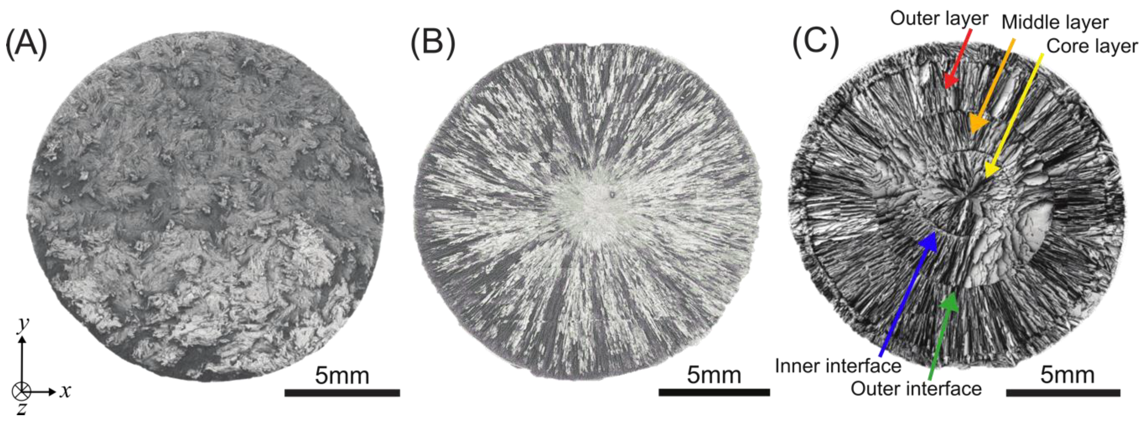
Images of the axial cross sections of samples in Figure 4 display the distinct microstructural differences between samples produced through the three freeze casting methods. Conventional freeze casts have a microstructure with random alignment (Figure 4A), radial freeze casts have a microstructure that is radially aligned (Figure 4B), and radial-concentric freeze casts have a radially aligned microstructure with concentric rings (Figure 4C). The radial-concentric freeze casts have three distinct layers. The outer and middle layer and the interface between them is a result of the first step in the radial-concentric method; we call this interface the “outer” interface. The core layer is the result of the second freeze casting step, and we call the interface between the core and middle layer the “inner” interface.
3.1. Radial and Radial-Concentric Freeze Casts: Axial Cross Sections
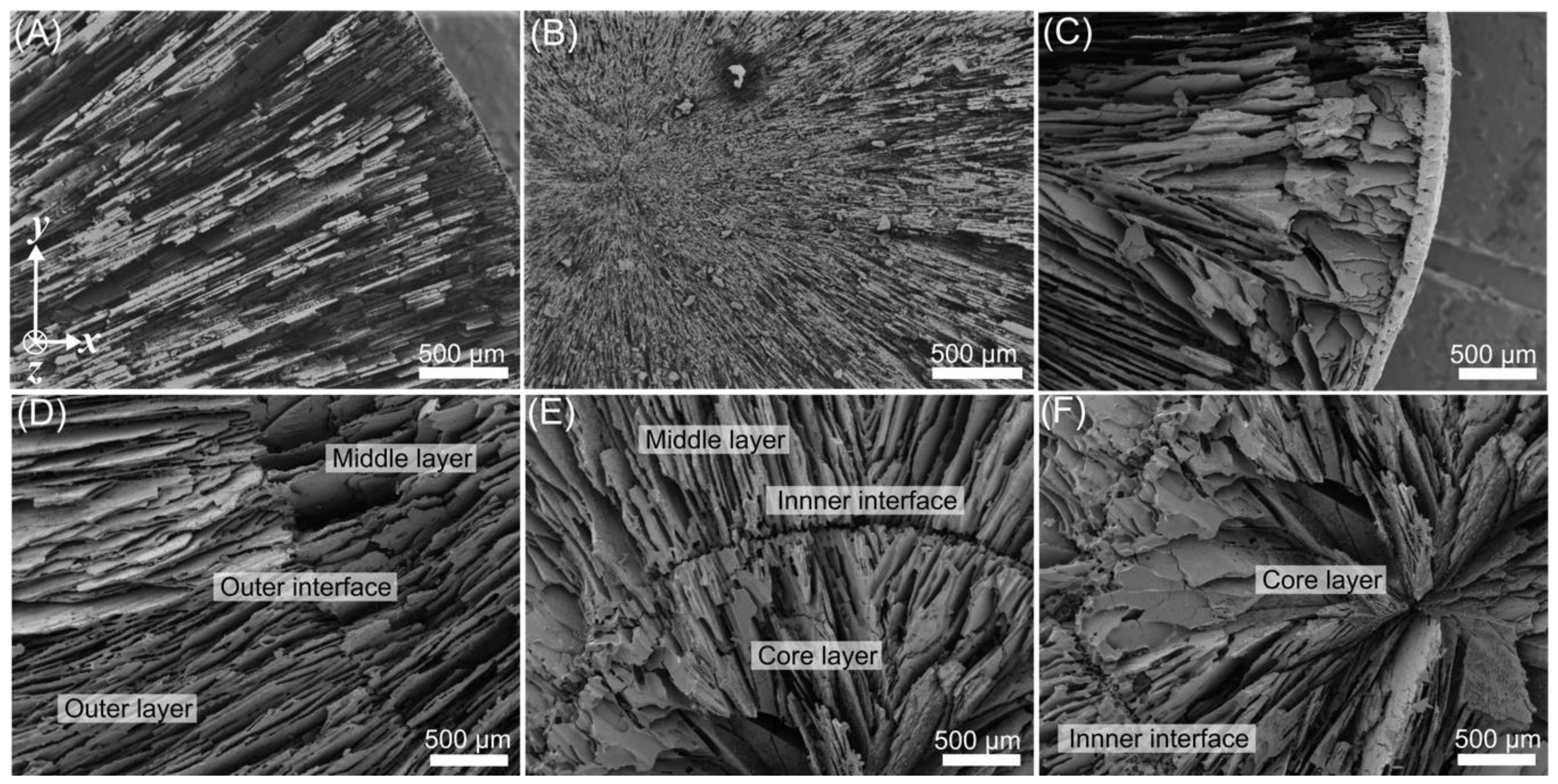
In Figure 5, close-up views of the microstructural features of radial and radial-concentric freeze casts are shown. Similar to other works in which water was used as the solvent [35,42], the walls of these samples are lamellar. The average wall thicknesses of the lamellae in uninfiltrated scaffolds were measured (Table 1). For radial freeze casts, the measurements were taken from near the outermost and innermost portions of the representative sample. For radial-concentric freeze casts, similar measurements were taken from the outermost and innermost portions of the outer and core layers.
In radial and radial-concentric freeze casts, there is a decrease in wall thicknesses when traveling from the outer surface of the sample to the center, which was also observed in previous radial freeze cast samples [42]. At the very center of both radial and radial-concentric freeze cast samples, it can be seen that lamellae become significantly smaller and more tightly spaced together (Figure 5). This spacing may be due to either an increase in the freezing front velocity (lamellae spacing is related to the freezing front velocity by a power law [35]) or the forces the ice crystals impose on each other as their growth converges towards the center. It is interesting to note that the center layers of radial-concentric samples not only have thinner wall sizes, but the walls also seem to meld together into superstructures where striations of the individual lamellae are still visible.
The porosities of uninfiltrated conventional, radial, and radial-concentric freeze cast samples were also measured. Porosities were found to be 52.6% ± 0.9%, 51.9% ± 2.7%, and 56.2% ± 2.9% for conventional, radial, and radial-concentric freeze casts, respectively. A student T-test showed statistically significant differences between the porosity of the radial-concentric scaffold with respect to porosities of conventional and radial scaffolds with p-values of p = 0.004 and p = 0.008, respectively. Although slurries with the same volume percentage of alumina particles were used in each method, the porosities from each freeze casting method may differ since slurries were not confined to a constant volume during freezing and were able to freely expand vertically. The porosities for both conventional and radial 30 vol.% scaffolds are higher than those reported in Tang et al. [42], where porosity for conventional scaffolds and radial scaffolds was found to be 38% and 42%, respectively. The discrepancy is likely due to the different experimental setups of this paper and that by Tang et al. [42], such as different freezing rates. With respect to other water-based freeze cast scaffolds made from 30 vol.% slurries, the porosities found in this study fall well within the range reported in a meta-analysis study done by Deville et al. [52].
3.2. Radial Freeze Cast: Longitudinal Cross Section
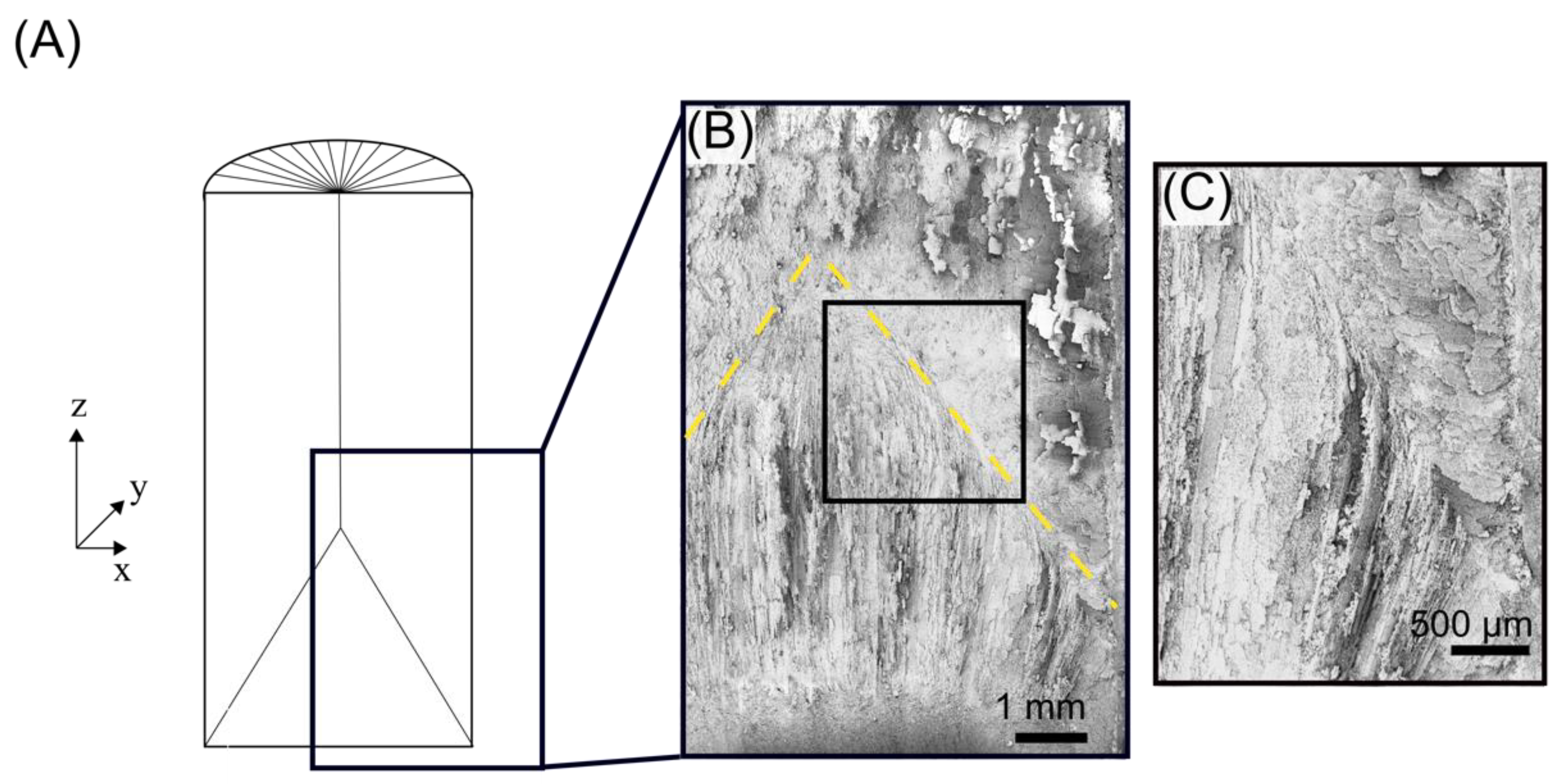
A longitudinal cross-section of a representative radial freeze cast sample is shown in Figure 6, with the lamellae visible. Recall that these freeze cast samples were freeze dried and sintered, so the lamellae shown form the negative of the ice crystal primary dendrites.
Through X-ray in-situ radiography and tomography, Deville et al. [52] observed the morphology of longitudinal cross sections of a slurry during conventional freeze casting. Two stages of freeze casting were noted: the “initial instants” of solidification, where the orientation of ice crystal growth proceeded randomly without long-range order, and a transition into a “steady state” growth, in which lamellar ice crystals grew parallel to the temperature gradients imposed in the slurry.
In the representative radial freeze cast shown in Figure 6, its equivalent initial instants of freezing encompass approximately the first centimeter of the sample, as measured from the bottom freezing surface. The length is similar to that previously reported in [53]. However, there are some differences between the longitudinal cross sections.
In [52], it was observed that in the initial instants of conventional freeze casting, there is a mix of two kinds of ice dendrites: ones whose primary axis of growth is longitudinally in the direction parallel to the thermal gradient and another whose growth axis is perpendicular to the thermal gradient (secondary dendrites), which arises from instabilities on the primary dendrites. The combination of the anisotropy of the ice crystals and the thermal gradient within the slurry cause the continued growth of these ice crystals to transition to being oriented parallel to the temperature gradient; this stage is the steady-state growth. In contrast, all initial crystal growth in the radial freeze cast (Figure 6B) is primarily parallel to the thermal gradient imposed by the bottom freezing surface. In addition, crystals grew radially inward from the copper mold; exposed radially oriented lamellae are shown in the region above the yellow dashed line in Figure 6B).
Furthermore, in radial freeze casting, the transition from the relatively turbulent initial instants to a steady-state is different from that observed in conventional freeze casting. In conventional freeze casting, this transition occurs gradually at approximately 1.5 cm through the longitudinal length of the sample [52]. In radial freeze casting, the transition from the initial instants to steady-state growth is well-defined. As shown in Figure 6B, crystals growing radially from the copper cylindrical mold meet crystals growing longitudinally from the bottom freezing surface at an interface oriented at ~45° with respect to the bottom surface.
Closer inspection of this interface shows that crystals growing longitudinally become perturbed from their original direction of growth, curving away from crystals growing radially (Figure 6C). It is not clear if these curved edges were influenced by the dual temperature gradients, created by the bottom freezing surface and the radial freezing surface, or by physical forces. These forces can arise due to the growth of the radially oriented crystals impeding the growth of longitudinally growing crystals.
3.3. Radial Concentric Freeze Casts: Outer Interface
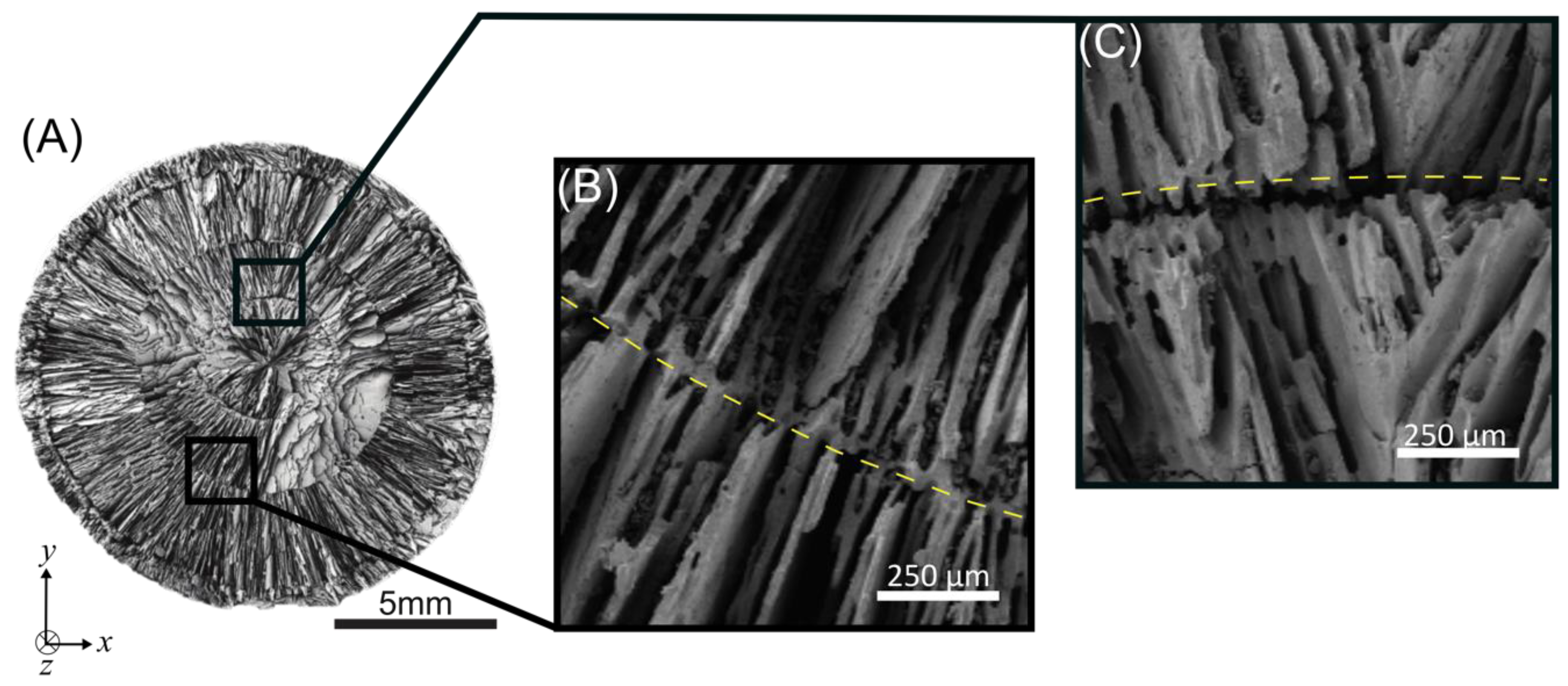
In Figure 7, representative close-up images of the outer and inner interfaces of the same radial-concentric freeze cast in Figure 4C are shown. Figure 7A is the same composite SEM image from Figure 4C but with different annotations. A representative close-up image of the interface of the outer interface of a radial-concentric freeze cast is shown in Figure 7B. This interface was formed in the first step of our radial-concentric freeze casting method, in which freezing fronts propagating from the inner copper pin and the outer copper mold met.
The phenomenon used here, the meeting of two freezing fronts, should have been present in the double-sided (top and bottom solidification plates) cooling setup previously reported [37]. However, it is not clear if the authors of this study observed an interface at the meeting of two freezing fronts. Similarly, the double-sided cooling method was previously explored to create more consistent lamellae spacing [53]. Yet, it is not clear from either the description of results or the images presented if the authors observed an interface. To date, it does not seem that anyone in the literature has commented on this particular facet of freeze casting. Considering that the use of multiple freezing surfaces may be investigated as a way to scale up freeze casting, it would be helpful to understand the properties at such an interface.
An explanation for the morphology of this outer interface may be found by considering the interactions of the tips of the ice crystals as they reach each other. Similar to conventional freeze casting, ice crystal growth first begins at the freezing surfaces (Figure 8A). Then, the tips of ice crystals growing from two opposite freezing fronts (Figure 8B) approach each other, and particles are pushed ahead until they become packed at that interface (Figure 8C). The tips of ice crystals growing inward from opposite directions may either merge or be stopped due to the packed particles, resulting in the “suture-like” structure seen in Figure 7C. Further work should be done to explore the factors that influence the morphology of the interface at the meeting of two freezing fronts.
3.4. Radial Concentric Freeze Casts: Inner Interface
The interface of the inner interface of the radial-concentric freeze cast is clearly defined, as shown in Figure 7C. While some bridging between the two layers is visible (Figure 5E), the inner interface appears to have less bridging compared to the outer interface shown in Figure 7B. This lack of bridging appears to result in a weak interface and is discussed in the mechanical test results. The inner ring was formed by pouring more liquid slurry into the hollow center of an already freeze cast solid and then freezing a second time. This freezing step was performed after equilibrating the temperatures of both the additional liquid slurry and the freeze cast solid to prevent melting and re-freezing of the freeze cast solid. The effects of this temperature equilibration on the morphology of the inner interface can be understood by comparing the sample shown in Figure 7B (equilibrated) against the sample shown in Figure S1 (not equilibrated) and against the samples produced through the two-step freeze casting method previously reported [41]. The latter two cases have blended interfaces due to the melting of the freeze cast solid as it comes into contact with the higher temperature liquid slurry and re-freezing upon freeze casting.
3.5. Mechanical Test Results
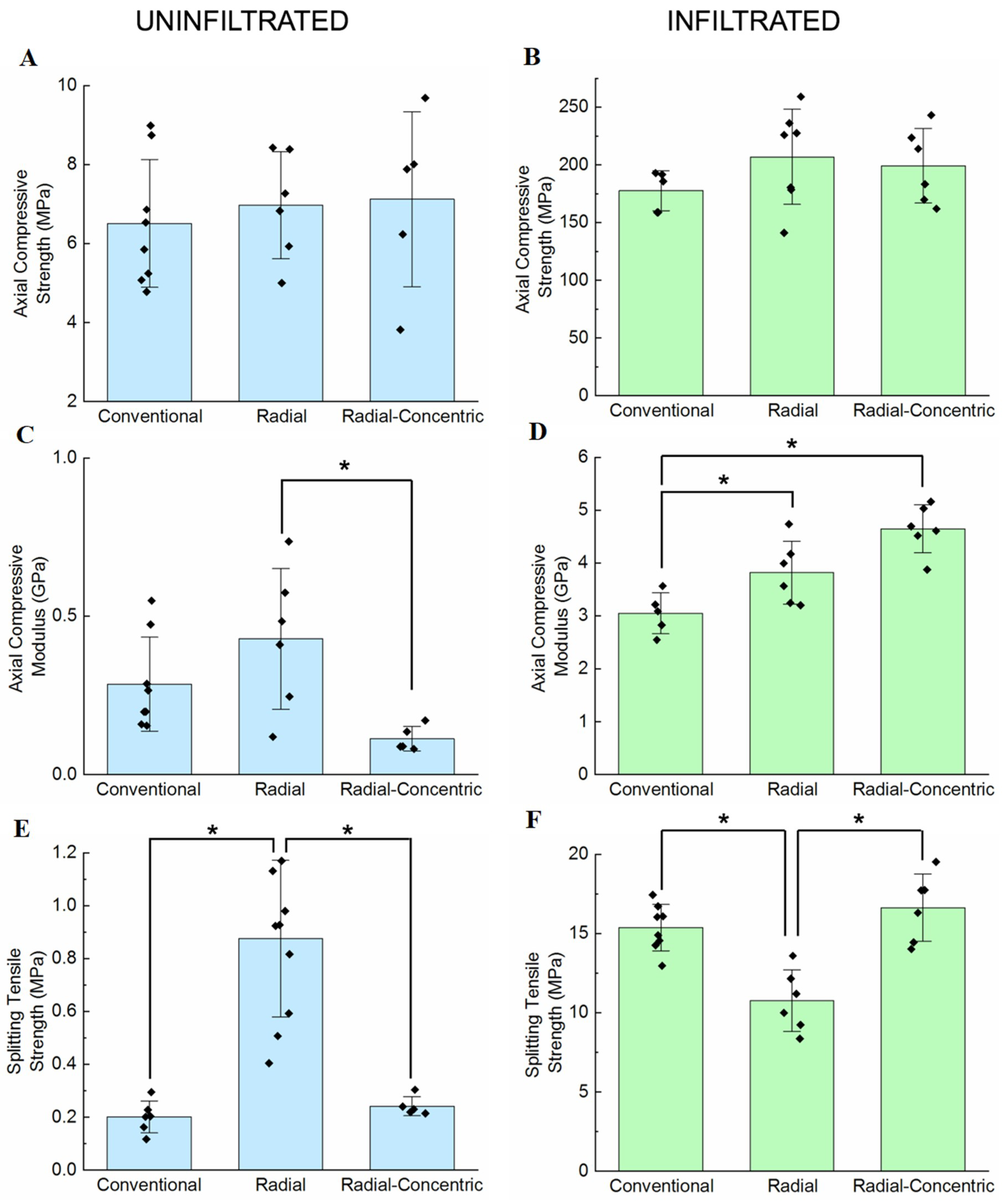
Figure 9 shows the mechanical testing results for uninfiltrated samples in the left column and infiltrated samples in the right column. Statistical similarities between results were analyzed using the Tukey test comparing structure; results that were significantly different are indicated by the brackets (labeled with asterisks) in Figure 9. Generally, structure has no effect on axial compressive strength for both uninfiltrated and infiltrated samples. However, structure affects both axial compressive modulus and splitting tensile strength, and the ways that structure affects these two properties change depending on whether the samples are uninfiltrated or infiltrated.
A general linear model was used to analyze sources of variance between samples; p-values from this analysis are summarized in Table S4 in the Supplementary Materials. This analysis shows that infiltration, but not structure, significantly influences axial compressive strength. Structure and infiltration both contribute to variances in axial compressive modulus; however, the combined effect of structure and infiltration contribute greater variance than the sum of their individual contributions, meaning that the interaction between the factors has a significant impact on axial compressive modulus. Similarly, structure and infiltration interact to have a greater combined effect on splitting tensile strength. Therefore, while infiltration affects axial compressive strength, axial compressive modulus, and splitting tensile strength, structure only affects axial compressive modulus and splitting tensile strength.
Axial compressive strength values for uninfiltrated conventional, radial, and radial-concentric samples are 6.5 ± 1.6 MPa, 6.7 ± 1.3 MPa, and 7 ± 2 MPa, respectively, and values for infiltrated conventional, radial, and radial-concentric samples were 180 ± 20 MPa, 200 ± 40 MPa, and 200 ± 30 MPa, respectively (Figure 9A). Infiltrated samples all have statistically similar axial compressive strengths. Therefore, structure does not affect the axial compressive strengths of the freeze cast samples while infiltration does. These results are likely due to all scaffold types having vertically aligned microstructures.
Axial compressive modulus values (shown in Figure 9C) for uninfiltrated conventional, radial, and radial-concentric samples are 290 ± 140 MPa, 400 ± 200 MPa, and 110 ± 40 MPa, respectively. Axial compressive modulus values for infiltrated conventional, radial, and radial-concentric samples are 3000 ± 400 MPa, 4000 ± 800 MPa, and 4600 ± 500 MPa, respectively. Uninfiltrated radial freeze casts have a significantly higher compressive modulus than uninfiltrated radial-concentric freeze casts and a similar compressive modulus to uninfiltrated conventional freeze casts. Infiltrated radial freeze casts have a modulus similar to that of infiltrated radial-concentric freeze casts, while infiltrated conventional freeze casts are less stiff. The differences between uninfiltrated and infiltrated samples highlight the importance of structure in multi-phase materials. Without infiltration, radial-concentric samples have the lowest axial compressive modulus amongst the three sample types; however, after infiltration, they have the highest axial compressive modulus. Oftentimes, hierarchical arrangements of stiff and soft phases of materials are the sources of remarkable mechanical properties that cannot be predicted by a simple “rule of mixtures” [54,55]. These results show that the radial and concentric structure of the ceramic and collagen phases in the porcupine fish spine may be the source of similar improvements.
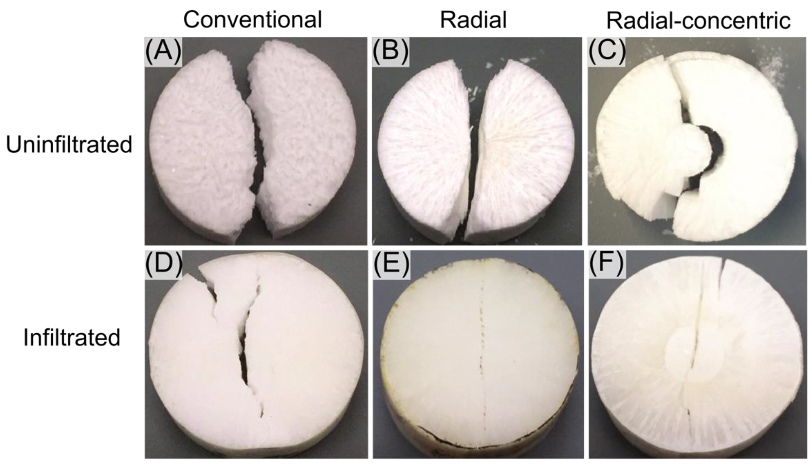
Finally, splitting tensile strengths (Brazilian tests) for uninfiltrated conventional, radial, and radial-concentric samples are 0.19 ± 0.08 MPa, 0.9 ± 0.3 MPa, and 0.21 ± 0.06 MPa, respectively (Figure 9E). Splitting tensile strengths for infiltrated conventional, radial, and radial-concentric samples are 15.4 ± 1.5 MPa, 10.8 ± 1.9 MPa, and 17 ± 2 MPa, respectively. Without infiltration, radial freeze casts have the highest splitting tensile strength out of the three freeze cast types. After infiltration, conventional and radial-concentric freeze cast samples have significantly higher splitting tensile strengths than radial freeze cast samples. These differences in the relative values of splitting tensile strengths in uninfiltrated and infiltrated samples might be attributed to the differences in what can be considered the weak phases in the microstructures of the samples. In all uninfiltrated samples, the porosity guided the crack formation. Similar behavior is seen in many biological materials, including the porcupine fish spine and bone [56]. Cracks travel through porous regions, forming patterns mirroring the alignment of the microstructures formed by lamellae. Figure 10A–C show crack patterns formed in representative uninfiltrated samples after Brazilian tests, which corroborate the results described above. For the conventional freeze cast sample (Figure 10A), the crack formed jagged surfaces due to the random orientation of the microstructure, and a crack was deflected when it encounters a region with lamellae aligned in a direction different from its original direction of travel. Radial samples (Figure 10B) tended to have relatively straight cracks, which followed along the radially aligned pores of the microstructure. Since there is relatively little bridging in the radial samples, the crack progressed through the whole sample easily. Finally, cracks in radial-concentric freeze cast samples (Figure 10C) followed the radially aligned pores, traveling through the outer interface, before diverting into the apparently weak interface of the inner interface. There was a clear crack deflection at every interface between the different layers. This difference in crack propagation between the two rings in radial-concentric samples may be caused by their different microstructures. The outer interface is more enmeshed than the relatively well-defined inner interface. However, the crack propagation along the inner ring may also be due to the difference in the radius of curvature; the smaller radius of curvature of the inner ring may make it more favorable for the crack to follow along that interface rather than break through the interface, as it did with the outer interface.
In the infiltrated samples, the weak regions were the brittle lamellae encased within the epoxy phase. Figure 10D-F show crack patterns formed in representative infiltrated samples after having undergone Brazilian tests. For conventional freeze cast samples, the random orientation of the lamellae meant that there was no specific path of weakness for the crack to travel; thus, the sample split down the center, where the stress was highest for the Brazilian test configuration [57,58]. In infiltrated radial freeze cast samples, the radial alignment of the relatively weak lamellae created a line down the center of the sample. The samples split in half along this line at a force lower than that needed to split a conventional freeze cast sample. In the radial-concentric freeze cast sample (Figure 10F), a crack did not form along the inner interface as it did in the uninfiltrated sample (Figure 10C) since this inner interface was filled with the epoxy phase, which is tougher than the brittle ceramic phase. The crack, which travels along one of the brittle lamellae, was surrounded on both sides by epoxy phases. Thus, once the crack reached the inner interface, it was forced to travel through the inner interface. These results indicate that the microstructure of the porcupine fish spine may be useful for resisting radial compressive loads.
The differing average porosities of the freeze cast types explored in this study should be considered when interpreting the mechanical test results shown here. As previously stated, the radial-concentric freeze casts tested have a higher porosity than either radial or conventional freeze casts; this difference, though not large, was enough to be statistically significant. For uninfiltrated freeze cast samples, increased porosity may decrease the strength of the material. However, there seems to be little effect from porosity on axial strength, since it is expected that the strengths would be similar due to the same axial alignment in all structure types. In addition, there is no statistically significant difference between axial compressive modulus and splitting tensile strength between conventional and radial-concentric scaffolds. For infiltrated freeze cast samples, increased porosity may cause the composite to take on more of the epoxy’s mechanical properties, and the increased amount of epoxy infiltrated into the scaffolds may serve to toughen the otherwise brittle scaffold.
Splitting tensile strengths of conventional and radial freeze cast samples from Tang et al. [42] were calculated based on the sample geometries and failure force values (failure force values were taken directly from data points given in the plots). At approximately 58 and 56% porosity for the conventional and radial freeze cast samples, respectively, the splitting tensile strengths were approximately 0.4 MPa and 0.7 MPa, respectively. The splitting tensile strength values for conventional freeze cast samples in the present work were much lower than those calculated from the results given in [42], despite the porosities of the samples in the former being lower than those in the latter. The differences may be attributed to differences in particle size, freezing, sintering procedures, and test sample geometry. Despite the differences between these results and previous results, both sets of results show similar trends of conventional freeze cast samples having lower splitting tensile strengths than radial freeze cast samples for uninfiltrated samples.
4. Conclusions
A novel radial-concentric freeze casting method inspired by the radial and concentric structure of the porcupine fish spine was successfully developed. Radial-concentric freeze cast porous ceramics were compared with samples freeze cast through radial and conventional freeze cast methods. It was found that:
- Radial-concentric freeze cast samples from our two-step freeze casting process had three layers. The outer two layers resulted from the first step in the process, in which two freezing fronts met to form an interface. The inner core layer resulted from the second step in the process, where another interface could be seen between this core layer and the layer formed in the first step of the freeze cast method.
- When infiltrated with epoxy, radial-concentric freeze cast ceramics had improved axial compressive modulus over uninfiltrated radial-concentric freeze casts, especially when compared against the effects of infiltration in conventional or radial freeze cast ceramics.
- Amongst uninfiltrated samples, radial-concentric freeze cast ceramics had one of the lowest splitting tensile strengths. With infiltration, radial-concentric freeze casts improved significantly to having the highest splitting tensile strength.
- In comparison, uninfiltrated radial freeze casts initially had the highest splitting tensile strength. Upon infiltration, the splitting tensile strength of radial freeze casts only improved moderately.
These findings suggest that the radial-concentric samples can be considered to have optimal improvements in all three mechanical properties once infiltrated and that the radial-concentric design of the porcupine fish spine may be optimized for radial compressive loads. Moreover, our results highlight the importance of structure in multi-phase materials. Mechanical properties between single phase and multi-phase materials with the same structure can differ significantly. These differences in mechanical behavior can be utilized for further understanding of how and why biological materials are optimal in certain loading conditions and for the design of improved engineering materials.
Supplementary Materials
The following are available online at https://0-www-mdpi-com.brum.beds.ac.uk/2571-6131/2/1/15/s1, Figure S1: SEM image of radial-concentric sample, Table S1: Axial compressive strength of infiltrated and uninfiltrated scaffolds, Table S2: Axial compressive modulus of infiltrated and uninfiltrated scaffolds, Table S3: Axial tensile strength of infiltrated and uninfiltrated scaffolds, Table S4: Analysis of variance.
Author Contributions
Conceptualization, F.Y.S. and J.R.M.; Methodology, F.Y.S. and J.R.M; Software, F.Y.S.; Validation, J.R.M. and F.Y.S.; Formal Analysis, F.Y.S. and J.R.M.; Investigation, J.R.M. and F.Y.S.; Resources, J.M.; Data Curation, F.Y.S. and J.R.M.; Writing—Original Draft Preparation, J.R.M. and F.Y.S.; Writing—Review and Editing, J.M., F.Y.S. and J.R.M.; Visualization, F.Y.S. and J.R.M.; supervision, F.Y.S.; Project Administration, F.Y.S.; Funding Acquisition, J.M.
Funding
This research was funded by a Multi-University Research Initiative through the Air Force Office of Scientific Research, grant number AFOSR-FA99550-15-1-009 and a National Science Foundation Biomaterials Grant, grant number DMR-1507978.
Acknowledgments
The work was performed in part at the San Diego Nanotechnology Infrastructure (SDNI) at UCSD, a member of the National Nanotechnology Coordinated Infrastructure, which is supported by the National Science Foundation, grant number ECCS-1542148.
Conflicts of Interest
The authors declare no conflict of interest.
References
- Maxwell, W.; Gurnick, R.; Francisco, A. Preliminary Investigation of the “Freeze-Casting” Method for Forming Refractory Powders; National Advisory Committee for Aeronautics (NACA): Washington, DC, USA, 1954.
- Chino, Y.; Dunand, D.C. Directionally freeze-cast titanium foam with aligned, elongated pores. Acta Mater. 2008, 56, 105–113. [Google Scholar] [CrossRef]
- Yook, S.-W.; Yoon, B.-H.; Kim, H.-E.; Koh, Y.-H.; Kim, Y.-S. Porous titanium (Ti) scaffolds by freezing TiH2/camphene slurries. Mater. Lett. 2008, 62, 4506–4508. [Google Scholar] [CrossRef]
- Li, J.C.; Dunand, D.C. Mechanical properties of directionally freeze-cast titanium foams. Acta Mater. 2011, 59, 146–158. [Google Scholar] [CrossRef]
- Ramos, A.I.; Dunand, D.C. Preparation and characterization of directionally freeze-cast copper foams. Metals 2012, 2, 265–273. [Google Scholar] [CrossRef]
- Dash, R.; Li, Y.; Ragauskas, A.J. Cellulose nanowhisker foams by freeze casting. Carbohydr. Polym. 2012, 88, 789–792. [Google Scholar] [CrossRef]
- Zhou, Y.; Fu, S.; Pu, Y.; Pan, S.; Ragauskas, A.J. Preparation of aligned porous chitin nanowhisker foams by directional freeze–casting technique. Carbohydr. Polym. 2014, 112, 277–283. [Google Scholar] [CrossRef] [PubMed]
- Zhou, Y.; Fu, S.; Pu, Y.; Pan, S.; Levit, M.V.; Ragauskas, A.J. Freeze-casting of cellulose nanowhisker foams prepared from a water-dimethylsulfoxide (DMSO) binary mixture at low DMSO concentrations. RSC Adv. 2013, 3, 19272–19277. [Google Scholar] [CrossRef]
- Donius, A.E.; Liu, A.; Berglund, L.A.; Wegst, U.G. Superior mechanical performance of highly porous, anisotropic nanocellulose–montmorillonite aerogels prepared by freeze casting. J. Mech. Behav. Biomed. Mater. 2014, 37, 88–99. [Google Scholar] [CrossRef] [PubMed]
- Qiu, L.; Liu, J.Z.; Chang, S.L.; Wu, Y.; Li, D. Biomimetic superelastic graphene-based cellular monoliths. Nat. Commun. 2012, 3, 1–7. [Google Scholar] [CrossRef] [PubMed]
- Antink, M.M.H.; Röpke, L.; Bartels, J.; Soltmann, C.; Kunzmann, A.; Rezwan, K.; Kroll, S. Porous ceramics with tailored pore size and morphology as substrates for coral larval settlement. Ceram. Int. 2018, 44, 16561–16571. [Google Scholar] [CrossRef]
- Moon, J.-W.; Hwang, H.-J.; Awano, M.; Maeda, K. Preparation of NiO–YSZ tubular support with radially aligned pore channels. Mater. Lett. 2003, 57, 1428–1434. [Google Scholar] [CrossRef]
- Deville, S. Freeze-casting of porous biomaterials: Structure, properties and opportunities. Materials 2010, 3, 1913–1927. [Google Scholar] [CrossRef]
- Yoon, B.H.; Koh, Y.H.; Park, C.S.; Kim, H.E. Generation of large pore channels for bone tissue engineering using camphene-based freeze casting. J. Am. Ceram. Soc. 2007, 90, 1744–1752. [Google Scholar] [CrossRef]
- Zhang, Y.; Zuo, K.; Zeng, Y.-P. Effects of gelatin addition on the microstructure of freeze-cast porous hydroxyapatite ceramics. Ceram. Int. 2009, 35, 2151–2154. [Google Scholar] [CrossRef]
- Fu, Q.; Rahaman, M.N.; Bal, B.S.; Brown, R.F. Proliferation and function of MC3T3-E1 cells on freeze-cast hydroxyapatite scaffolds with oriented pore architectures. J. Mater. Sci. Mater. Med. 2009, 20, 1159–1165. [Google Scholar] [CrossRef] [PubMed]
- Deville, S.; Saiz, E.; Tomsia, A.P. Freeze casting of hydroxyapatite scaffolds for bone tissue engineering. Biomaterials 2006, 27, 5480–5489. [Google Scholar] [CrossRef] [PubMed] [Green Version]
- Suetsugu, Y.; Hotta, Y.; Iwasashi, M.; Sakane, M.; Kikuchi, M.; Ikoma, T.; Higaki, T.; Ochiai, N.; Tanaka, M. Structural and tissue reaction properties of novel hydroxyapatite ceramics with unidirectional pores. Key Eng. Mater. 2007, 330–332, 1003–1006. [Google Scholar] [CrossRef]
- Yoon, B.-H.; Choi, W.-Y.; Kim, H.-E.; Kim, J.-H.; Koh, Y.-H. Aligned porous alumina ceramics with high compressive strengths for bone tissue engineering. Scr. Mater. 2008, 58, 537–540. [Google Scholar] [CrossRef]
- Hong, C.; Zhang, X.; Han, J.; Du, J.; Han, W. Ultra-high-porosity zirconia ceramics fabricated by novel room-temperature freeze-casting. Scr. Mater. 2009, 60, 563–566. [Google Scholar] [CrossRef]
- Bouville, F.; Maire, E.; Meille, S.; Van de Moortèle, B.; Stevenson, A.J.; Deville, S. Strong, tough and stiff bioinspired ceramics from brittle constituents. Nat. Mater. 2014, 13, 508–514. [Google Scholar] [CrossRef] [PubMed] [Green Version]
- Porter, M.M.; Yeh, M.; Strawson, J.; Goehring, T.; Lujan, S.; Siripasopsotorn, P.; Meyers, M.A.; McKittrick, J. Magnetic freeze casting inspired by nature. Mater. Sci. Eng. A 2012, 556, 741–750. [Google Scholar] [CrossRef]
- Porter, M.M.; Meraz, L.; Calderon, A.; Choi, H.; Chouhan, A.; Wang, L.; Meyers, M.A.; McKittrick, J. Torsional properties of helix-reinforced composites fabricated by magnetic freeze casting. Compos. Struct. 2015, 119, 174–184. [Google Scholar] [CrossRef]
- Frank, M.B.; Naleway, S.E.; Haroush, T.; Liu, C.-H.; Siu, S.H.; Ng, J.; Torres, I.; Ismail, A.; Karandikar, K.; Porter, M.M. Stiff, porous scaffolds from magnetized alumina particles aligned by magnetic freeze casting. Mater. Sci. Eng. C 2017, 77, 484–492. [Google Scholar] [CrossRef] [PubMed]
- Uhlmann, D.R.; Chalmers, B.; Jackson, K.A. Interaction between particles and a solid-liquid interface. J. Appl. Phys. 1964, 35, 2986–2993. [Google Scholar] [CrossRef]
- Araki, K.; Halloran, J.W. Porous ceramic bodies with interconnected pore channels by a novel freeze casting technique. J. Am. Ceram. Soc. 2005, 88, 1108–1114. [Google Scholar] [CrossRef]
- Peppin, S.S.; Worster, M.G.; Wettlaufer, J. Morphological instability in freezing colloidal suspensions. Proc. R. Soc. Lond. A Math. Phys. Eng. Sci. 2006, 463, 723–733. [Google Scholar] [CrossRef]
- Peppin, S.S.L.; Wettlaufer, J.S.; Worster, M.G. Experimental verification of morphological instability in freezing aqueous colloidal suspensions. Phys. Rev. Lett. 2008, 100, 1–4. [Google Scholar] [CrossRef] [PubMed]
- Deville, S.; Maire, E.; Lasalle, A.; Bogner, A.; Gauthier, C.; Leloup, J.; Guizard, C. In Situ X-Ray Radiography and Tomography Observations of the Solidification of Aqueous Alumina Particles Suspensions. Part II: Steady State. J. Am. Ceram. Soc. 2009, 92, 2497–2503. [Google Scholar] [CrossRef] [Green Version]
- Naleway, S.E.; Christopher, F.Y.; Hsiong, R.L.; Sengupta, A.; Iovine, P.M.; Hildebrand, J.A.; Meyers, M.A.; McKittrick, J. Bioinspired intrinsic control of freeze cast composites: Harnessing hydrophobic hydration and clathrate hydrates. Acta Mater. 2016, 114, 67–79. [Google Scholar] [CrossRef]
- Porter, M.M.; McKittrick, J.; Meyers, M.A. Biomimetic materials by freeze casting. JOM 2013, 65, 720–727. [Google Scholar] [CrossRef]
- Mukai, S.R.; Nishihara, H.; Tamon, H. Formation of monolithic silica gel microhoneycombs (SMHs) using pseudosteady state growth of microstructural ice crystals. Chem. Commun. 2004, 874–875. [Google Scholar] [CrossRef] [PubMed]
- Koh, Y.H.; Lee, E.J.; Yoon, B.H.; Song, J.H.; Kim, H.E.; Kim, H.W. Effect of polystyrene addition on freeze casting of ceramic/camphene slurry for ultra-high porosity ceramics with aligned pore channels. J. Am. Ceram. Soc. 2006, 89, 3646–3653. [Google Scholar] [CrossRef]
- Shanti, N.O.; Araki, K.; Halloran, J.W. Particle redistribution during dendritic solidification of particle suspensions. J. Am. Ceram. Soc. 2006, 89, 2444–2447. [Google Scholar] [CrossRef]
- Deville, S.; Saiz, E.; Tomsia, A.P. Ice-templated porous alumina structures. Acta Mater. 2007, 55, 1965–1974. [Google Scholar] [CrossRef] [Green Version]
- Fukasawa, T.; Ando, M.; Ohji, T.; Kanzaki, S. Synthesis of porous ceramics with complex pore structure by freeze-dry processing. J. Am. Ceram. Soc. 2001, 84, 230–232. [Google Scholar] [CrossRef]
- Deville, S.; Saiz, E.; Nalla, R.K.; Tomsia, A.P. Freezing as a path to build complex composites. Science 2006, 311, 515–518. [Google Scholar] [CrossRef] [PubMed]
- Nakata, M.; Tanihata, K.; Yamaguchi, S.; Suganuma, K. Fabrication of porous alumina sintered bodies by a gelate-freezing method. J. Ceram. Soc. Jpn. 2005, 113, 712–715. [Google Scholar] [CrossRef]
- Zhang, H.; Hussain, I.; Brust, M.; Butler, M.F.; Rannard, S.P.; Cooper, A.I. Aligned two-and three-dimensional structures by directional freezing of polymers and nanoparticles. Nat. Mater. 2005, 4, 787–793. [Google Scholar] [CrossRef] [PubMed]
- Deville, S. Freeze-casting of porous ceramics: A review of current achievements and issues. Adv. Eng. Mater. 2008, 10, 155–169. [Google Scholar] [CrossRef]
- Tang, Y.; Zhao, K.; Hu, L.; Wu, Z. Two-step freeze casting fabrication of hydroxyapatite porous scaffolds with bionic bone graded structure. Ceram. Int. 2013, 39, 9703–9707. [Google Scholar] [CrossRef]
- Tang, Y.; Miao, Q.; Qiu, S.; Zhao, K.; Hu, L. Novel freeze-casting fabrication of aligned lamellar porous alumina with a centrosymmetric structure. J. Eur. Ceram. Soc. 2014, 34, 4077–4082. [Google Scholar] [CrossRef]
- Leis, J.M. Nomenclature and distribution of the species of the porcupinefish family Diodontidae (Pisces, Teleostei). Mem. Mus. Vic. 2006, 63, 77–90. [Google Scholar] [CrossRef] [Green Version]
- Brainerd, E.L. Pufferfish inflation: Functional morphology of postcranial structures in Diodon holocanthus (Tetraodontiformes). J. Morphol. 1994, 220, 243–261. [Google Scholar] [CrossRef] [PubMed]
- Su, F.Y.; Bushong, E.A.; Deerinck, T.J.; Seo, K.; Herrera, S.; Graeve, O.A.; Kisailus, D.; Lubarda, V.A.; McKittrick, J. Spines of the porcupine fish: Structure, composition, and mechanical properties. J. Mech. Behav. Biomed. Mater. 2017, 73, 38–49. [Google Scholar] [CrossRef] [PubMed] [Green Version]
- Zhu, D.; Ortega, C.F.; Motamedi, R.; Szewciw, L.; Vernerey, F.; Barthelat, F. Structure and mechanical performance of a “modern” fish scale. Adv. Eng. Mater. 2012, 14, B185–B194. [Google Scholar] [CrossRef]
- Yu, Z.B.; Krstic, V.D. Fabrication and characterization of laminated SiC ceramics with self-sealed ring structure. J. Mater. Sci. 2003, 38, 4735–4738. [Google Scholar] [CrossRef]
- Marshall, D.B.; Ratto, J.J.; Lange, F.F. Enhanced fracture toughness in layered microcomposites of Ce-ZrO2 and Al2O3. J. Am. Ceram. Soc. 1991, 74, 2979–2987. [Google Scholar] [CrossRef]
- Williams, J.T.; Carpenter, K.E.; Van Tassell, J.L.; Hoetjes, P.; Toller, W.; Etnoyer, P.; Smith, M. Biodiversity assessment of the fishes of Saba Bank Atoll, Netherlands Antilles. PLoS ONE 2010, 5, 1–37. [Google Scholar] [CrossRef]
- ASTM International. ASTM C39/C39M-18, Standard Test Method for Compressive Strength of Cylindrical Concrete Specimens; ASTM International: West Conshohocken, PA, USA, 1921. [Google Scholar]
- ASTM International. ASTM D3967-16, Standard Test Method for Splitting Tensile Strength of Intact Rock Core Specimens; ASTM International: West Conshohocken, PA, USA, 1981. [Google Scholar]
- Deville, S.; Meille, S.; Seuba, J. A meta-analysis of the mechanical properties of ice-templated ceramics and metals. Sci. Tech. Adv. Mater. 2015, 16, 043501. [Google Scholar] [CrossRef] [PubMed] [Green Version]
- Deville, S.; Maire, E.; Lasalle, A.; Bogner, A.; Gauthier, C.; Leloup, J.; Guizard, C. In Situ X-Ray Radiography and Tomography Observations of the Solidification of Aqueous Alumina Particle Suspensions—Part I: Initial Instants. J. Am. Ceram. Soc. 2009, 92, 2489–2496. [Google Scholar] [CrossRef]
- Waschkies, T.; Oberacker, R.; Hoffmann, M.J. Control of lamellae spacing during freeze casting of ceramics using double-side cooling as a novel processing route. J. Am. Ceram. Soc. 2009, 92, S79–S84. [Google Scholar] [CrossRef]
- Fratzl, P.; Weinkamer, R. Nature’s hierarchical materials. Prog. Mater. Sci. 2007, 52, 1263–1334. [Google Scholar] [CrossRef] [Green Version]
- Sabet, F.A.; Su, F.Y.; McKittrick, J.; Jasiuk, I. Mechanical Properties of Model Two-Phase Composites with Continuous Compared to Discontinuous Phases. Adv. Eng. Mater. 2018, 20, 1–6. [Google Scholar] [CrossRef]
- Nalla, R.K.; Kinney, J.H.; Ritchie, R.O. Mechanistic fracture criteria for the failure of human cortical bone. Nat. Mater. 2003, 2, 164–168. [Google Scholar] [CrossRef] [PubMed] [Green Version]
- Li, D.; Wong, L.N.Y. The Brazilian disc test for rock mechanics applications: Review and new insights. Rock Mech. Rock Eng. 2013, 46, 269–287. [Google Scholar] [CrossRef]
Figure 1.
Packing of ceramic particles in between ice crystals during freeze casting. (A) A slurry of ceramic particles (green) suspended within water, in contact with the freezing surface before cooling is applied. (B) Cooling of the freezing surface begins, and ice crystals begin to form at the freezing surface. (C) Cooling continues and ice crystals grow deeper into the slurry, packing more solute particles between them. (D) Conventional freeze casting setup with a polyvinyl chloride (PVC) mold.

Figure 2.
(A) Porcupine fish fully inflated, with defensive spines oriented outwards [49]. (B) Schematic of ultrastructure and microstructure of the porcupine fish spine, adapted from [45].

Figure 3.
Overview of freeze casting methods (bottom freezing surface underneath molds not shown). (A) Conventional freeze casting, (B) radial freeze casting, and (C) radial-concentric freeze casting. A copper pin is placed in the center of the copper mold. Then, the direction of freezing, shown by the gray arrows, is outward from the copper pin and inward from the copper mold. The pin is removed and the remaining void is filled with liquid slurry, and then cooling is applied again.

Figure 4.
Freeze cast samples composed of 30 vol.% alumina. Full composite images of axial cross sections of each sample were created by stitching together multiple images, with each individual image taken at approximately 38× magnification. Samples freeze cast through (A) conventional, (B) radial, and (C) radial-concentric methods are shown. In (C) the outer, middle, and core layers are pointed out by the red, orange, and yellow arrows, respectively. Inner and outer interfaces are pointed out by the blue and green arrows, respectively.

Figure 5.
Scanning electron microscopy (SEM) images of freeze cast samples composed of 30 vol.% alumina. Radial freeze cast (A) outermost region and (B) innermost region. Radial-concentric freeze cast (C) outer layer, outer region; (D) outer layer, inner region; (E) core layer, outer region; (F) core layer, inner region.

Figure 6.
Longitudinal cross section of radial freeze cast sample. (A) Schematic diagram of longitudinally sectioned freeze cast sample. (B) Composite scanning electron microscopy image of the longitudinal section in boxed area in (A) with yellow dotted line delineating the meeting of lamellae growing longitudinally from the bottom freezing surface and lamellae growing radially from the cylindrical copper mold. (C) Zoomed-in view of boxed area in (B).

Figure 7.
(A) Scanning electron microscopy images of inner and outer rings in a representative radial-concentric freeze cast sample. (B) Zoomed-in image of the boxed region in (A) of the inner ring, with yellow dashed line highlighting the interface. (C) Zoomed-in image of the boxed region in (A) of the outer ring, with yellow dashed line highlighting the interface.

Figure 8.
Schematic of packing of ceramic particles at the outer interface. (A) The setup of the radial-concentric freeze casting method in the first step of the process (showing a three-dimensional view per the axes in the bottom left corner), with a schematic representation of the boxed region shown in a top-down view in (B,C). (B) Initial solidification of water at each freezing surface. (C) The growth of ice crystals at opposing freezing surfaces. (D) Meeting of ice crystals packing ceramic particles at the interface.

Figure 9.
Results from mechanical testing, where brackets labeled with asterisks (*) indicate results that were found to be significantly different under Tukey pairwise comparisons for structure. Axial compressive strength in (A) uninfiltrated and (B) infiltrated samples from axial compression tests. Axial compressive modulus of (C) uninfiltrated and (D) infiltrated samples measured from axial compression tests. Splitting tensile strength of (E) uninfiltrated and (F) infiltrated samples measured from Brazilian tests.

Figure 10.
Crack patterns in representative samples after Brazilian testing. (A) Uninfiltrated conventional. (B) Uninfiltrated radial. (C) Uninfiltrated radial-concentric. (D) Infiltrated conventional. (E) Infiltrated radial. (F) Infiltrated radial-concentric.
Figure 10.
Crack patterns in representative samples after Brazilian testing. (A) Uninfiltrated conventional. (B) Uninfiltrated radial. (C) Uninfiltrated radial-concentric. (D) Infiltrated conventional. (E) Infiltrated radial. (F) Infiltrated radial-concentric.


Table 1.
Wall thicknesses of lamellae in uninfiltrated scaffolds, where Nm is the number of measurements taken and SD is the standard deviation. Measurements were taken using ImageJ software. Porosity was calculated as described in the methods section with N = 8, 6, and 12 for conventional, radial, and radial-concentric, respectively.
| Freeze Cast Type | Zone | Region | Nm | Thickness ± SD (µm) | Porosity ± SD (%) |
|---|---|---|---|---|---|
| Conventional | N/A | N/A | 50 | 46 ± 15 | 52.6% ± 0.9% |
| Radial | N/A | Outer | 50 | 14 ± 4 | 51.9% ± 2.7% |
| Radial | N/A | Inner | 50 | 8 ± 2 | |
| Radial-concentric | Outer layer | Outer | 53 | 19 ± 6 | 56.2% ± 2.9% |
| Radial-concentric | Outer layer | Inner | 51 | 17 ± 3 | |
| Radial-concentric | Core layer | Outer | 53 | 21 ± 6 | |
| Radial-concentric | Core layer | Inner | 50 | 12 ± 5 |
© 2019 by the authors. Licensee MDPI, Basel, Switzerland. This article is an open access article distributed under the terms and conditions of the Creative Commons Attribution (CC BY) license (http://creativecommons.org/licenses/by/4.0/).
Share and Cite
MDPI and ACS Style
Su, F.Y.; Mok, J.R.; McKittrick, J. Radial-Concentric Freeze Casting Inspired by Porcupine Fish Spines. Ceramics 2019, 2, 161-179. https://0-doi-org.brum.beds.ac.uk/10.3390/ceramics2010015
AMA Style
Su FY, Mok JR, McKittrick J. Radial-Concentric Freeze Casting Inspired by Porcupine Fish Spines. Ceramics. 2019; 2(1):161-179. https://0-doi-org.brum.beds.ac.uk/10.3390/ceramics2010015
Chicago/Turabian StyleSu, Frances Y., Joyce R. Mok, and Joanna McKittrick. 2019. "Radial-Concentric Freeze Casting Inspired by Porcupine Fish Spines" Ceramics 2, no. 1: 161-179. https://0-doi-org.brum.beds.ac.uk/10.3390/ceramics2010015