Tunable Magneto-Dielectric Material for Electrically Small and Reconfigurable Antenna Systems at Vhf Band

 and
and 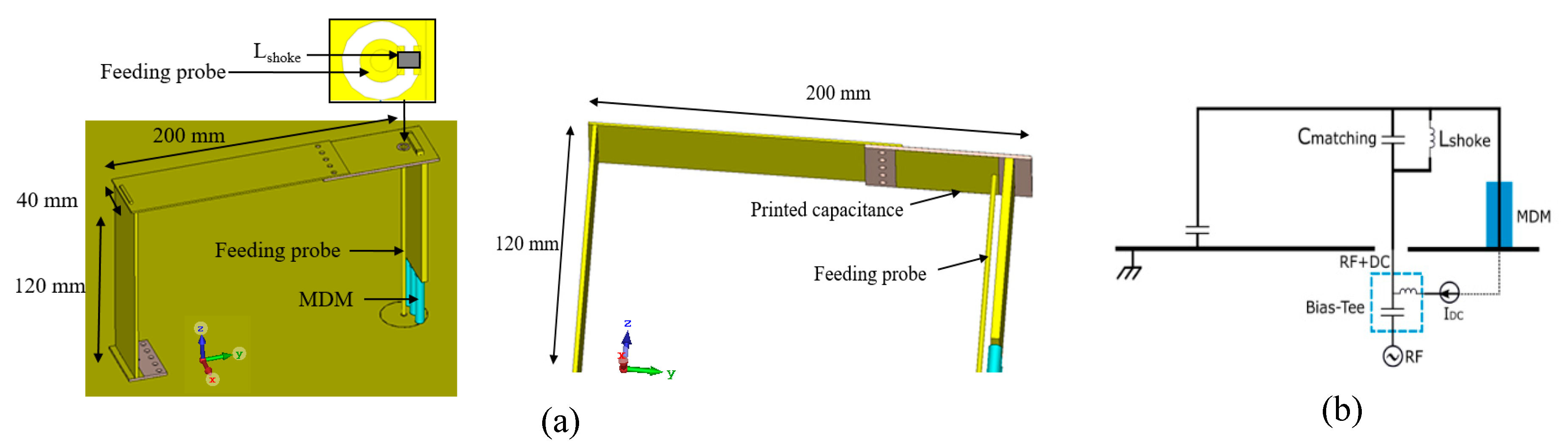
Abstract
:1. Introduction
2. Materials and Methods
2.1. Antenna Design Description
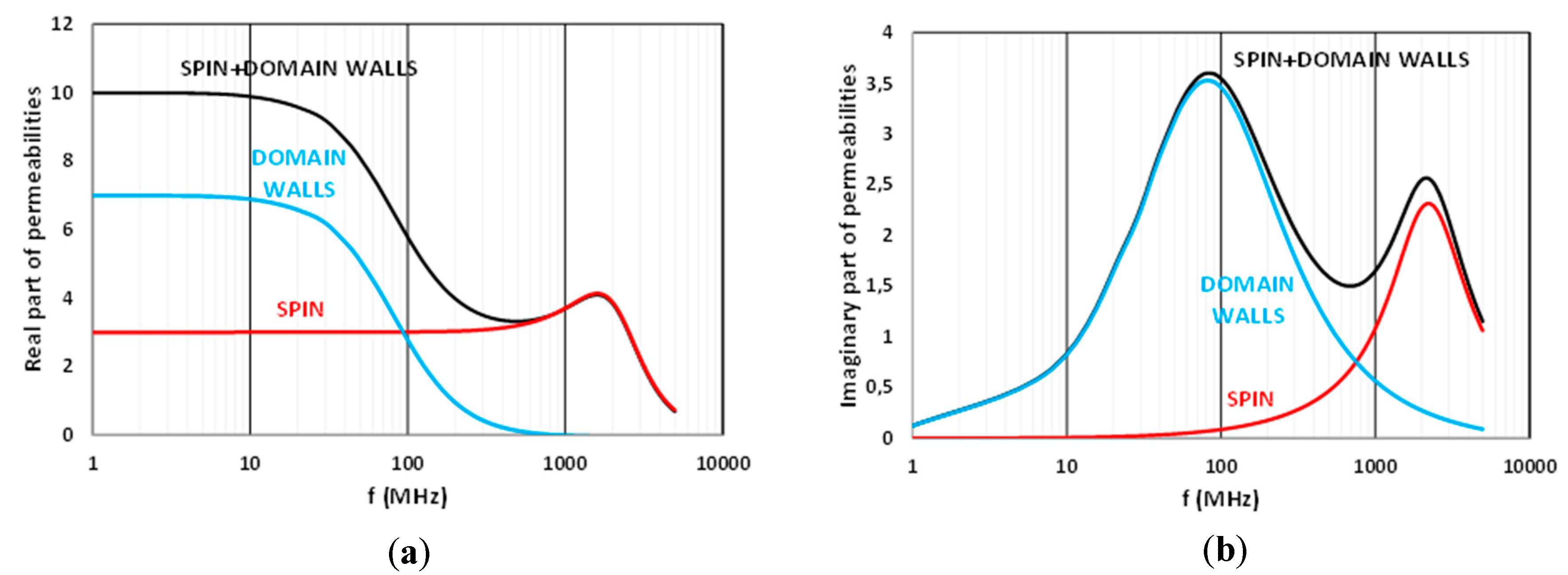
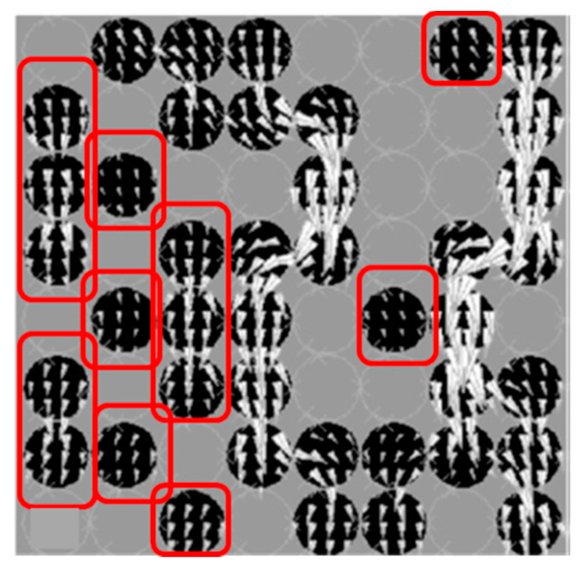
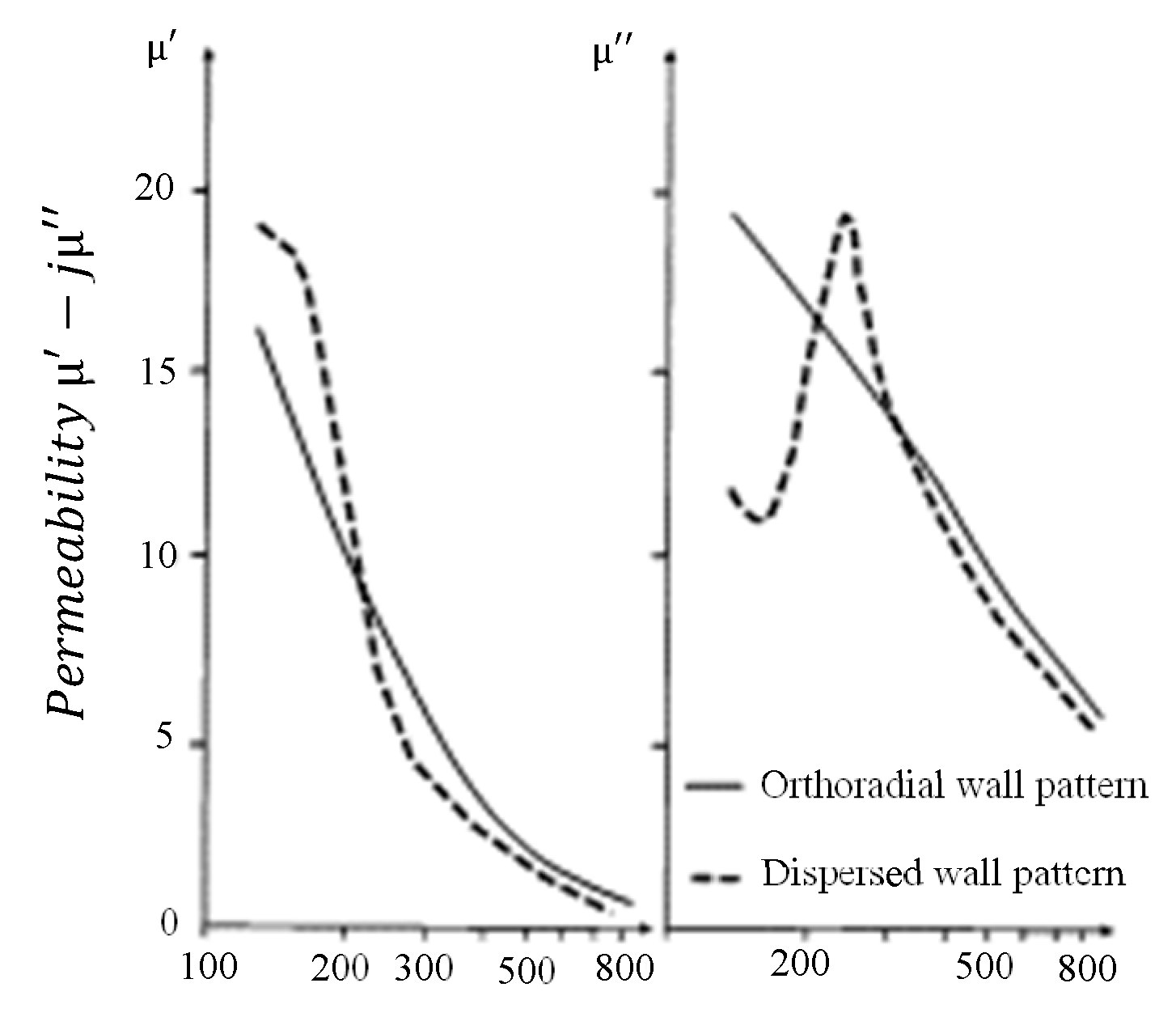
2.2. Structural and Main Electromagnetic Features of MDM Samples
3. Results
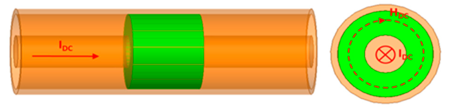
3.1. Measurements of Sample’s Permeability Dynamics as a Function of an Applied DC Magnetic Field
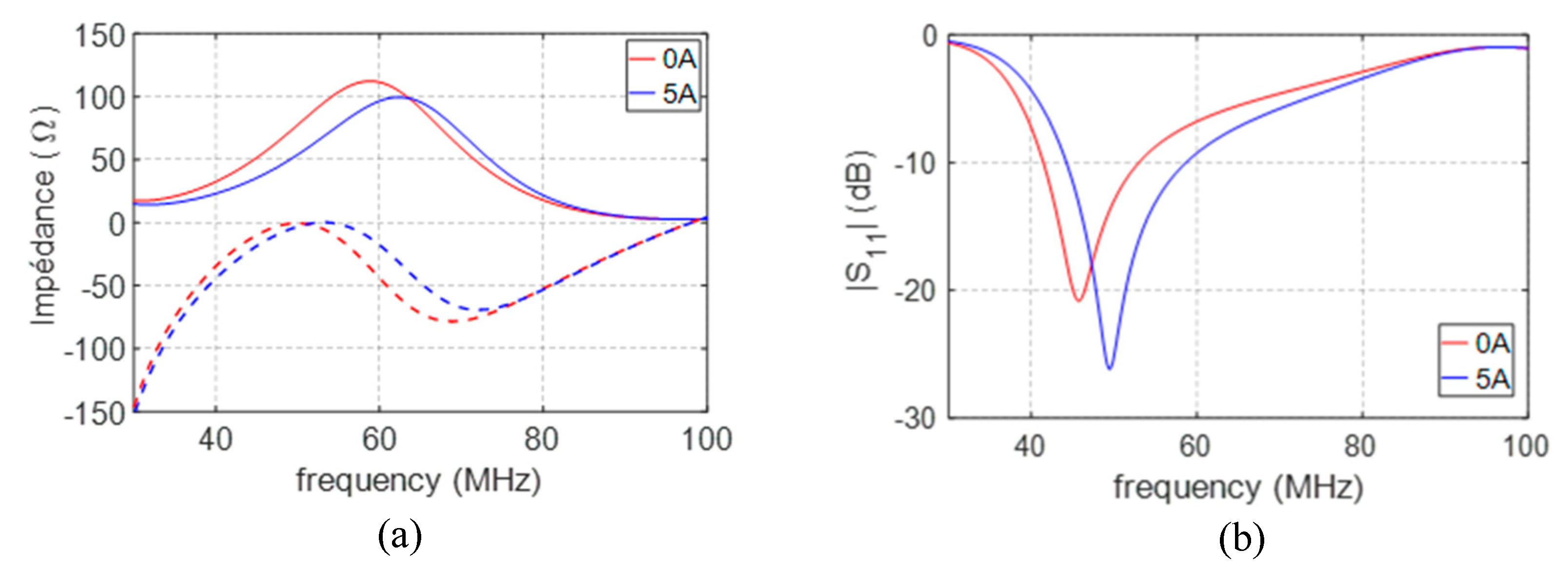
3.2. Frequency Agility Potential of IFA Loaded with S2 MDM
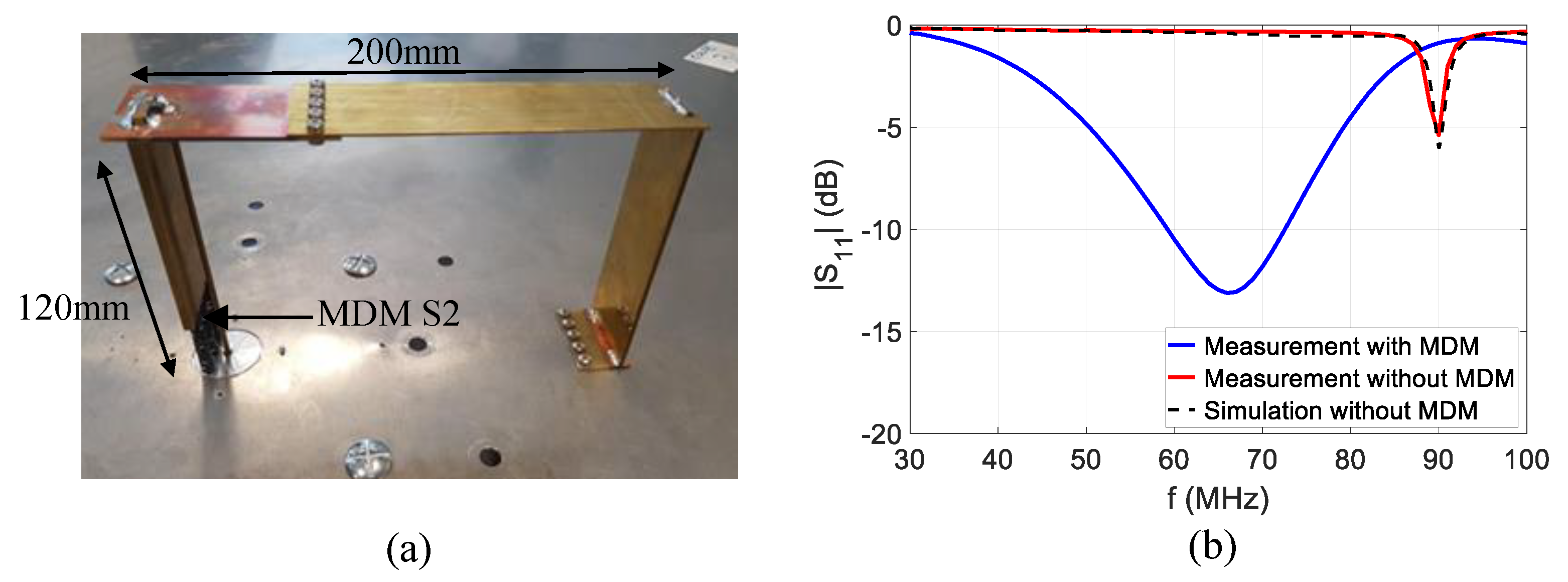
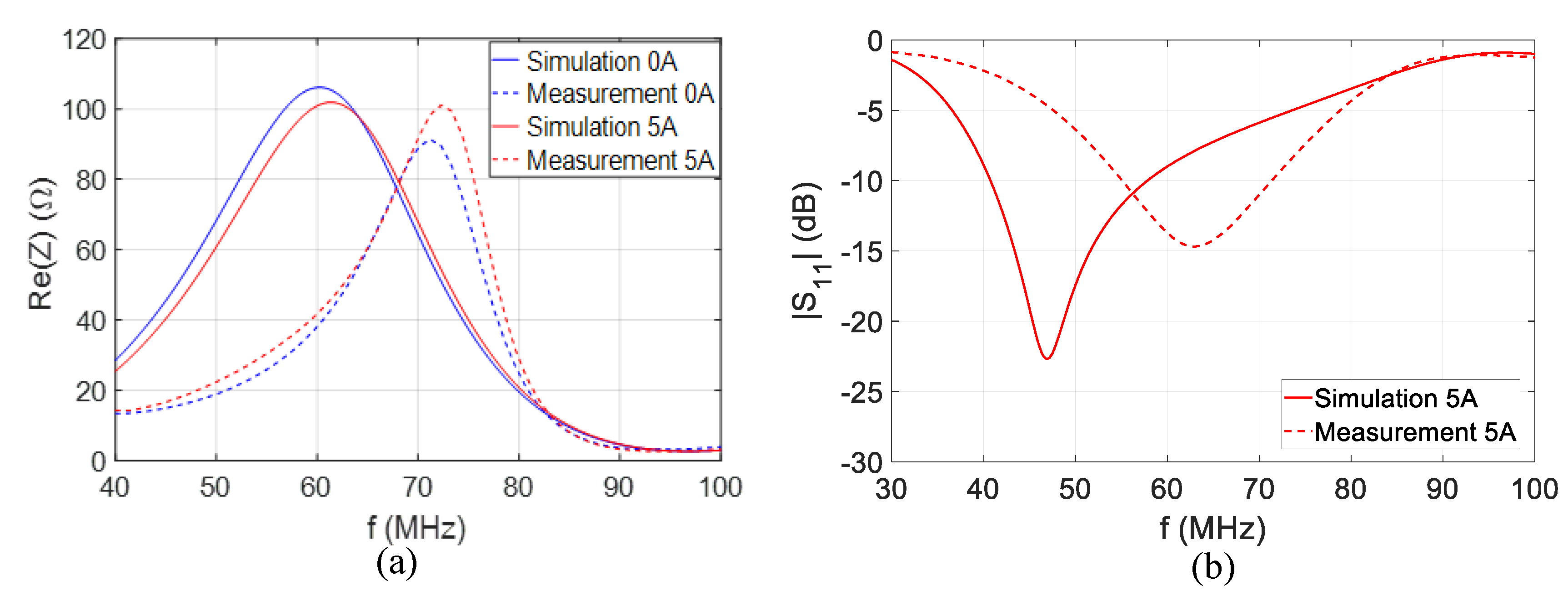
3.3. Antenna’s Frequency Agility Measurement
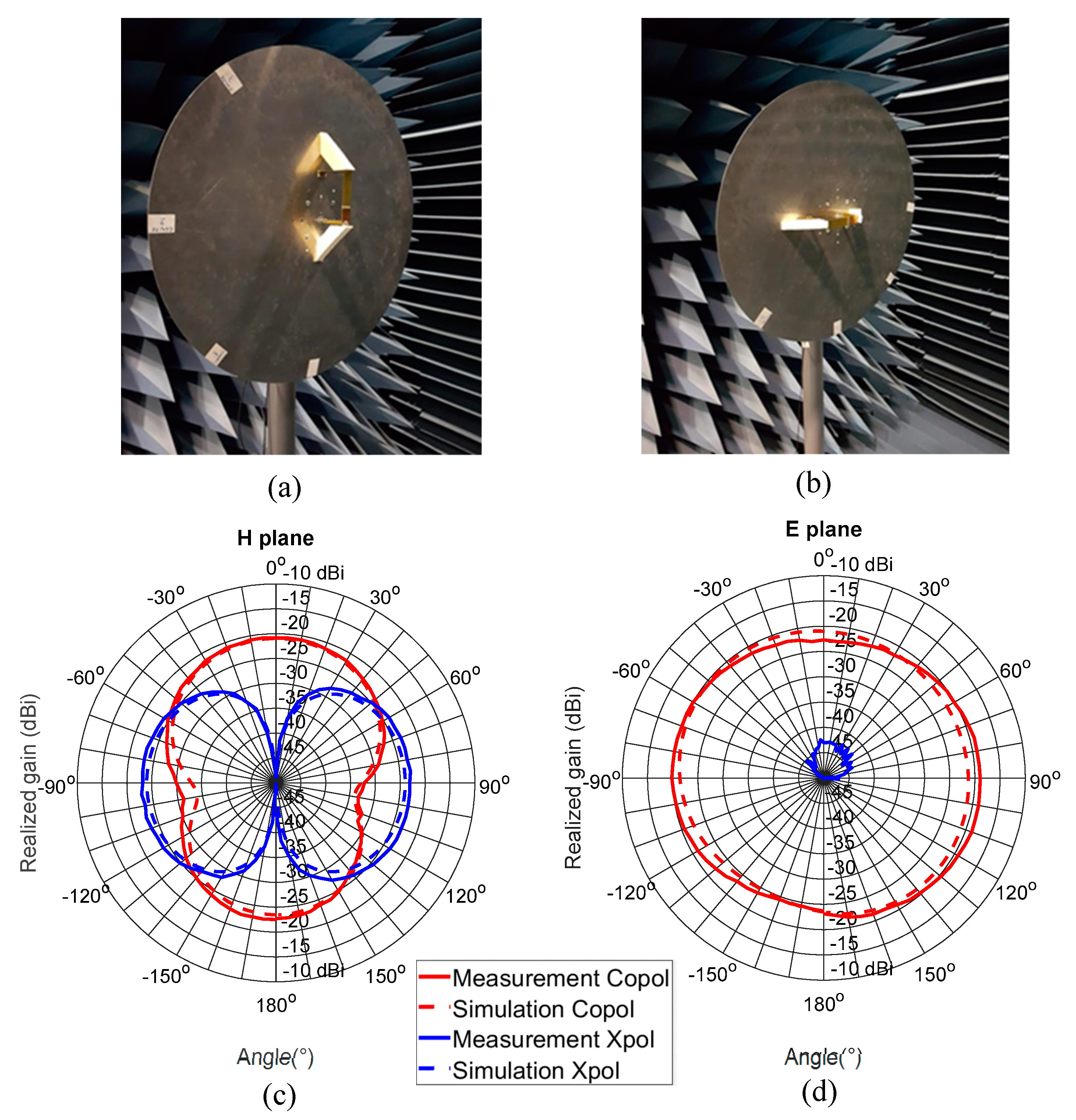
3.4. Measurement Results of IFA’s Radiation Properties Loaded with S2 MDM
4. Conclusions
5. Patents
Author Contributions
Funding
Conflicts of Interest
References
- Chu, L.J. Physical limitations of omni-directional antennas. J. Appl. Phys. 1948, 19, 1163–1175. [Google Scholar] [CrossRef] [Green Version]
- Wheeler, H.A. Fundamental limitations of small antennas. Proc. IRE 1947, 35, 1479–1484. [Google Scholar] [CrossRef]
- Harrington, R.F. Effect of antenna size on gain, bandwidth, and efficiency. J. Res. Natl. Bur. Stand. 1960, 64D, 1–12. [Google Scholar] [CrossRef]
- Yaghjian, A.D.; Best, S.T. Impedance, bandwidth, and Q of antennas. IEEE Trans. Antennas Propag. 2005, AP-53, 1298–1324. [Google Scholar] [CrossRef]
- Yang, S.; Zhang, C.; Pan, H.K.; Fathy, A.E.; Nair, V.K. Frequency-Reconfigurable Antennas for Multiradio Wireless Platforms. IEEE Microw. Mag. 2009, 10, 66–83. [Google Scholar] [CrossRef]
- Laur, V.; Queffelec, P.; Rasoanoavy, F.; Lebedev, G.; Viala, B.; Pham, M.T. Microwave Magnetoelectric Couplings in FeCoB/Piezoelectric Bilayers. IEEE Trans. Mag. 2013, 49, 1060–1063. [Google Scholar] [CrossRef]
- Niamien, C.; Collardey, S.; Sharaiha, A.; Mahdjoubi, K. Compact Expressions for Efficiency and Bandwidth of Patch Antennas Over Lossy Magneto-Dielectric Materials. IEEE Antennas Wirel. Propag. Lett. 2011, 10, 63–66. [Google Scholar] [CrossRef]
- Louzir, A.; Minard, P.; Pintos, J. Parametric study on the use of magneto-dielectric materials for antenna miniaturization. In Proceedings of the 2010 IEEE Antennas and Propagation Society International Symposium, Toronto, ON, Canada, 11–17 July 2010; 2010. [Google Scholar] [CrossRef]
- Kabalan, A.; Sharaiha, A.; Tarot, A.C.; Mattei, J.L.; Souriou, D.; Queffelec, P. Impact of magneto-dielectric materials on the miniaturization of UWB monopole antennas. In Proceedings of the 2018 International Workshop on Antenna Technology (iWAT), Shanghai, China, 5–7 March 2018. [Google Scholar]
- Batel, L.; Pintos, J.-F.; Delaveaud, C. Design of a monopolar wire-plate antenna loaded with magneto-dielectric material. Eucap 2017. [Google Scholar] [CrossRef]
- Globus, A. Universal hysteresis loop for soft ferrimagnetic polycristals. Physics B 1977, 86, 943–944. [Google Scholar] [CrossRef]
- King, R.; Harrison, C.; Denton, D. Transmission-line missile antennas. IRE Trans. Antennas Propag. 1960, 8, 88–90. [Google Scholar] [CrossRef] [Green Version]
- Batel, L.; Delaveaud, C.; Pintos, J.F. Miniaturization of a Monopolar Wire-Plate Antenna Using Magneto-Dielectric Material. In Proceedings of the 2019 IEEE International Workshop on Antenna Technology (iWAT), Miami, FL, USA, 3–6 March 2019; pp. 91–94. [Google Scholar] [CrossRef]
- Mattei, J.-L.; Le Guen, E.; Chevalier, A.; Tarot, A.C. Experimental determination of magnetocrystalline anisotropy constants and saturation magnetostriction constants of NiZn and NiZnCo ferrites intended to be used for natennas miniaturization. J. Magn. Magn. Mater. 2015, 374. [Google Scholar] [CrossRef]
- Mattei, J.-L.; Souriou, D.; Chevalier, A. Magnetic and dielectric properties in the UHF frequency band of half-dense Ni-Zn-Co ferrites ceramics with Fe-excess and Fe-deficiency. J. Magn. Magn. Mater. 2017, 447. [Google Scholar] [CrossRef]
- Mattei, J.-L.; Le Floc’h, M. Percolative behaviour and demagnetizing effects in disordered heterostructures. J. Magn. Magn. Mater. 2003, 257, 335–345. [Google Scholar] [CrossRef]
- Le Floc’h, M.; Globus, A. Effects of perpendicular stresses on the magnetization processes of polycrystalline magnetic materials. J. Appl. Phys. 1987. [Google Scholar] [CrossRef]
- Doumouya, V.; Kabalan, A.; Chevalier, A.; Mattei, J.-L.; Tarot, A.-C.; Delaveaud, C.; Sharahia, A.; Laur, V. Characterization of ferrite tunability at microwave frequencies: Application to VHF tunable antennas. In Proceedings of the 2019 IEEE Asia-Pacific Microwave Conference (APMC), Singapore, 10–13 December 2019. [Google Scholar]
- Berro, R.; Bories, S.; Delaveaud, C. Transmission Line Model For Lossy Inverted F Antenna Miniaturization. In Proceedings of the 2019 International Conference on Electromagnetics in Advanced Applications (ICEAA), Granada, Spain, 9–13 September 2019; pp. 0797–0802. [Google Scholar]


© 2020 by the authors. Licensee MDPI, Basel, Switzerland. This article is an open access article distributed under the terms and conditions of the Creative Commons Attribution (CC BY) license (http://creativecommons.org/licenses/by/4.0/).
Share and Cite
Batel, L.; Mattei, J.-L.; Laur, V.; Chevalier, A.; Delaveaud, C. Tunable Magneto-Dielectric Material for Electrically Small and Reconfigurable Antenna Systems at Vhf Band. Ceramics 2020, 3, 276-286. https://0-doi-org.brum.beds.ac.uk/10.3390/ceramics3030025
Batel L, Mattei J-L, Laur V, Chevalier A, Delaveaud C. Tunable Magneto-Dielectric Material for Electrically Small and Reconfigurable Antenna Systems at Vhf Band. Ceramics. 2020; 3(3):276-286. https://0-doi-org.brum.beds.ac.uk/10.3390/ceramics3030025
Chicago/Turabian StyleBatel, Lotfi, Jean-Luc Mattei, Vincent Laur, Alexis Chevalier, and Christophe Delaveaud. 2020. "Tunable Magneto-Dielectric Material for Electrically Small and Reconfigurable Antenna Systems at Vhf Band" Ceramics 3, no. 3: 276-286. https://0-doi-org.brum.beds.ac.uk/10.3390/ceramics3030025