Grain-Size Effects on Multi-Wire Slurry Sawing of Translucent Alumina Ceramics


1
Fraunhofer-Institut für Keramische Technologien und Systeme IKTS Dresden Gruna, Winterbergstr. 28, 01277 Dresden, Germany
2
Technische Universität Bergakademie Freiberg, Agricolastr. 17, 09599 Freiberg, Germany
*
Author to whom correspondence should be addressed.
Ceramics 2020, 3(4), 428-439; https://0-doi-org.brum.beds.ac.uk/10.3390/ceramics3040036
Submission received: 7 September 2020
/
Revised: 28 September 2020
/
Accepted: 12 October 2020
/
Published: 13 October 2020
Abstract
:The technology of multi-wire sawing is well established in the production of silicon wafers but can also be applied in the production of ceramic substrates. In this study, the influence of the Al2O3-grain size of the alumina ceramic on the efficiency of the multi-wire slurry process was investigated. The grain size of HIPed alumina ceramics was changed by heat treatment processes at 1350 °C and 1400 °C. A B4C slurry was used for the investigation of the cutting of high purity alumina ceramic. With increasing grain size of the ceramic, the efficiency of the sawing process increases. The analysis of the as-cut surface morphology of the substrates shows a change in material removal from trans- to intergranular micro-fracture with increasing grain size. Furthermore, grain coarsening leads to substrates with increased roughness values and reduced biaxial strength.
1. Introduction
Multi-wire sawing has become the leading technology in wafer production for semiconductor materials. Substrates of other materials such as ceramics are also required. Alumina ceramic substrates are used for sensor applications, energy storage technology, and applications in power electronics [1,2]. Therefore, multi-wire sawing is a potential technology to produce such components. The main advantages of multi-wire slurry sawing are the low heat dissipation during machining, resulting in a low surface damage depth and the small material kerf width due to wire diameters ≤0.3 mm. In analogy to lapping or polishing, low surface roughness can be achieved with properly adjusted machining parameters [3]. A schematic drawing of a multi-wire slurry saw is shown in Figure 1. The rotation of the wire guide rollers accelerates the wire as the top plate presses the workpiece onto the wire web. From the slurry nozzles, a mixture of carrier fluid and abrasive particles is applied on the wire field. The mixture adheres to the wires, is carried along by the wire speed, and is fed into the workpiece. The forced movement of the abrasive particles in the sawing channel causes the chipping of the material. The sawing channel, which is constantly deepened by the material removal, leads to separate ceramic substrates at the end of a sawing process [4].
A detailed parameter study on the most important machine process and workpiece geometry parameters for multi-wire sawing of translucent, fine-grained high-density alumina ceramics is published in [6]. It was observed that a larger workpiece length, a higher number of wafers, and the abrasive particle size reduction lead to a decreased cutting rate in the sawing process and therefor longer process times. A maximum feed rate of 18 µm/min could be applied under the investigated conditions, which are much lower than typical (feed rates for Silicon >700 µm/min [7]). The substrates showed a high surface quality (roughness values Ra 0.2–0.3 µm, biaxial strength >1000 MPa). The results show that translucent alumina ceramics with extreme hardness and wear resistance represent a major challenge for the multi-wire sawing process. However, no data concerning the influence of the microstructure on the cutting process exist. Therefore, the aim of this study was the investigation of the influence of the alumina grain size on the multi-wire slurry sawing process.
2. Materials and Methods
2.1. Materials and Characterization Methods
To determine the influence of the ceramic grain size on the multi-wire sawing process, heat treatments were conducted to coarsen the grain size of the alumina ceramic. The heat treatment processes were run in a tube furnace (RHT08/17, Nabertherm, Lilienthal, Germany). The original material was post-sintered at 1350 °C and 1400 °C in an air atmosphere with a holding time of 1 h and a heating and cooling rate of 3 K/min. The density of the samples was measured with the Archimedes method and the hardness by Vicker’s indentation tests (according to DIN EN 843-4). KIC was estimated by the Vicker’s indentation fracture toughness test using the formula of Niihara (HP) [8]. The microstructure, chemical composition, and surface texture were examined using a scanning electron microscope (NVision 40, Carl Zeiss Microscopy GmbH, Oberkochen, Germany) with a field emission cathode (FESEM) and an energy dispersive detector of characteristic X-rays (EDX). The mean grain diameter was measured by the linear intercept method on images of polished cross-the sections (>300 grains, 4 SEM-micrographs at a magnification of 7500×). The biaxial strength was tested on the cut substrates with ball on three balls testing [9,10] with a loading rate of 0.5 mm/min, the radius of the ball of 3.175 mm, the radius of supporting balls of 5 mm and a sample size of 20 × 20 × thickness of the substrate (approx.: 0.23 mm). The Weibull modulus was determined according to DIN EN 843-5.
2.2. Experimental Multi-Wire Sawing Procedure
The multi-wire sawing processes were conducted on a multi-wire slurry saw (DS265, Meyer and Burger, Thun, Switzerland). The sawing parameters of the experiment are listed in Table 1. A standard structured steel wire (coating: copper, zinc) with a nominal diameter of 115 µm was used. Boron-carbide grains with the size F-400 were used as a cutting agent in the loose abrasive slurry. The B4C abrasive size and distribution were measured with a laser diffraction particle size analyzer (LS 13 320, Beckman Coulter, Brea, CA, USA).
In the DS265 a multi-component dynamometer is used to determine the force profile during the process (sensor is mounted between the beam and the traversing unit). The force sensor provides reliable data for a feed speed >0.1 mm/min. The alumina ceramic was cut with a feed speed of 0.02 mm/min due to the high hardness and wear resistance. Therefore, it could not be used to characterize the cutting processes. The bow of the wire web was used instead to analyze the cutting behavior, as already described in [6]. If the wire is in contact with the workpiece and the cutting speed is lower than the feed speed (constant control parameter), a bow of the wire web will form under the workpiece (Figure 2). The size of the wire bow is an indicator of the cutting rate of a material. The smaller the bow, the better the cutting ability.
In this study, the influence of ceramic grain size on the wire bow was tested. Therefore, alumina ceramic blocks with a d50-grain size of 0.44, 0.64, and 0.90 µm were used for cutting. After a feed length of 25 mm, the process is stopped, and the workpiece is moved out of the wire web. A feed length of 25 mm is needed to guarantee a constant material removal rate with a stable size of the bow (steady-state level). The length of the repositioning movement of the workpiece against the feed direction, until the wire web is strait (measuring error: ±50 µm) represents the bow of the wire web. The experimental routine and the sawing parameters are previously described in [6].
The surface roughness and thickness of the ceramic substrates (17 substrates per sample) were characterized by an optical profilometer (MicroProf R 300, FRT GmbH, Bergisch Gladbach, Germany). The optical profilometer has a lateral resolution of 2 µm and a vertical resolution of 6 nm. The roughness values were calculated according to the standard DIN EN ISO 4287. To efficiently characterize the surface morphology, roughness measurements along lines with a length of 5.6 mm were carried out per substrate. One line was measured parallel to the wire movement direction (Ra ||) and one perpendicular to it (Ra ⊥).
3. Results
3.1. Microstructure and Properties of the Alumina Ceramic
The main properties of the original and grain coarsened Al2O3-ceramics samples are listed in Table 2.
Figure 3 and Figure 4 show the SEM-micrographs of the polished cross-sections and Figure 5 summarizes the results of the grain size analysis. The d50-grain size of the HT1400 sample is doubled by the heat treatment temperature of 1400 °C for 1 h in comparison to the O1 material, from 0.44–0.90 µm. To inhibit discontinuous grain growths in the manufacturing process of fine-grained, translucent alumina ceramics, magnesium oxide (<1 wt.%) as a sintering additive is used [11]. EDX- measurements show a slightly increased size of MgO-rich-precipitations at grain junctions and triple points with grain coarsening (Figure 4). The MgO-rich-precipitations are found sporadically in the O1 sample and have a size <0.1 µm. In the samples with grain coarsening HT1350 and HT1400 the size of the Mg-rich-precipitations increases to 0.3–0.4 µm.
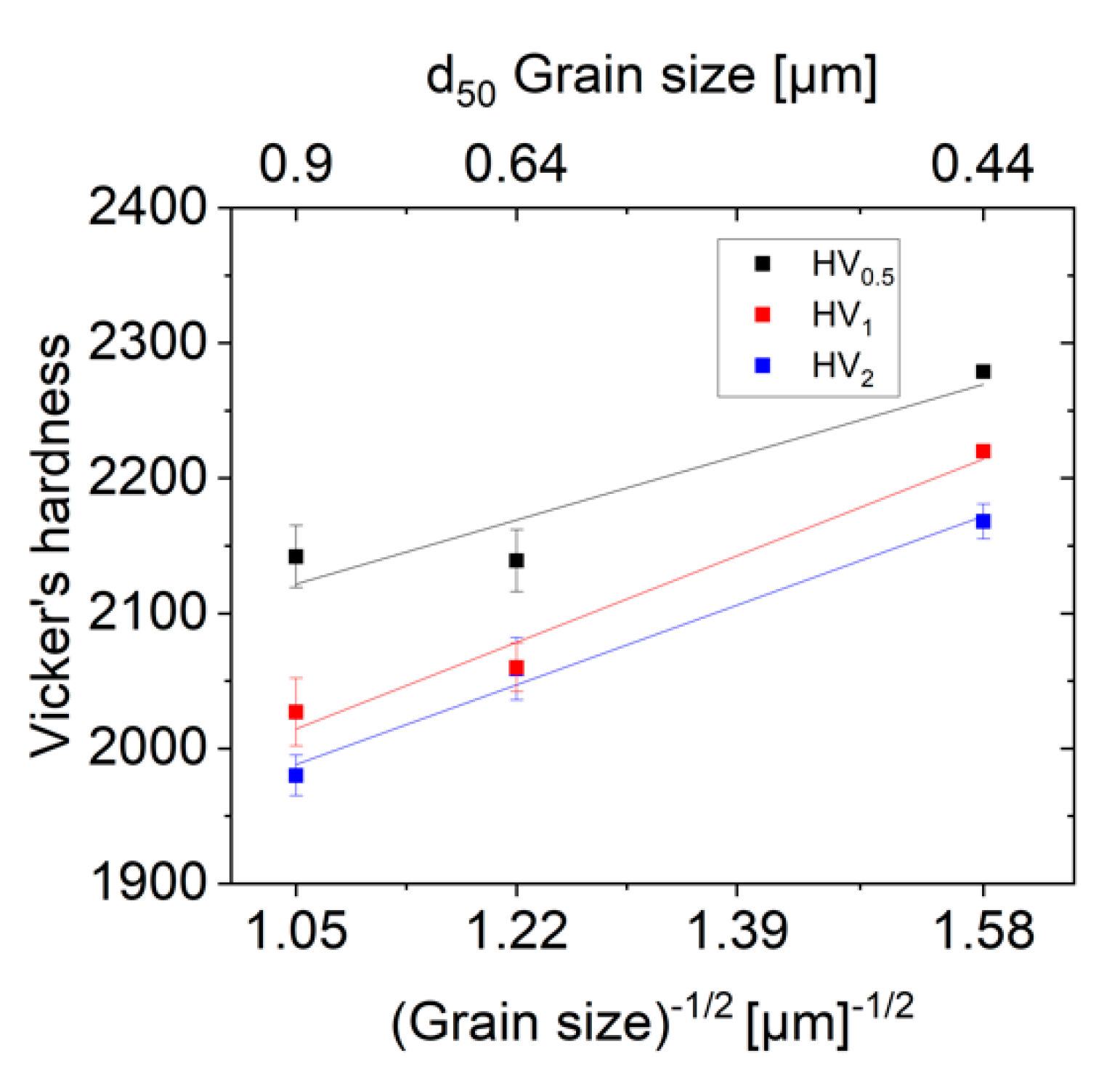
A decrease in the Vicker’s hardness of about 10% was measured with increasing grain size in the investigated range of 0.44–0.90 µm (Figure 6). The hardness measurements for the HV1 and HV2 load follow the Hall-Patch relation. The measurement error at a load of HV0.5 is increased due to the small indentation size, which limits the accuracy of the measurement. The phenomenon of an increase in hardness with the reciprocal root of the grain size is known as a Hall-Petch-type-relation and is described in the literature for alumina ceramics with a grain size >0.2 µm and a load of HV0.4-10 [12]. The increasing hardness is based on the increasing dislocation blocking at the grain boundaries with decreasing grain size [13]. The KIC-value decreases from 3.5–2.8 MPa*m0.5 with increasing grain size.
3.2. Influence of the Ceramic Grain Size on the Size of the Wire Bow
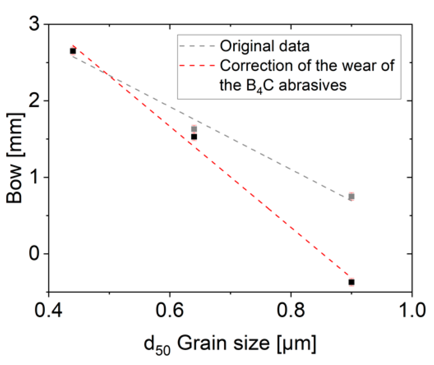
The sawing rate was evaluated using the wire bow as described in the experimental section. The original values of the sizes of the wire bows are displayed in Figure 7. The values were measured after a constant time of 1250 min. These values include not only the influence of the ceramic structure but also the dependence on the B4C grain size in the slurry since the B4C wears out during the sawing process. Therefore, the mean grain sizes of the B4C grits in the slurry differ in the individual experiments. In earlier work, a linear decrease of the B4C d50-grit size of −10.2 µm per sawn m2 of O1-material was observed [6]. In this study, an area of 0.032 m2 is cut in each process, resulting in a decrease of the B4C d50-grit size of 0.3 µm per sawing process. Due to the small change in grit size, a constant B4C d50-grit size is assumed during one cut. However, the experiments shown here were not performed directly one after the other resulting in larger deviations of the mean grain sizes of B4C in the slurry. Therefore, the influence of the grain size must be corrected for a clearer analysis of the data. The grit size of O1 was measured before the process (d50-value of 21.6) and the values at the end of the process of cutting O1 can be estimated at a d50-value of 21.3 µm. After cut #2 (HT1400) a d50-grit size of 15.7 µm was measured. The decrease in the d50-value of −5.6 µm is caused by cutting 0.55 m2 of O1 material in further processes and cut #2 (HT1400) carried out with the slurry-tank. The degree of wear of the B4C abrasives required a re-dosing of fresh abrasives into the slurry-tank bevor the cut #3 to ensure process stability. The addition of fresh abrasive grits results in a wider grain size distribution compared to cut #1 and #2 and an increased d50-grit size compared to cut #2. A d50-grit size of 20.8 µm was measured after cut #3 (HT1350). Based on these measurements the following B4C d50-grit sizes were used for the bow correction:
- d50 = 21.3 µm for cut #1 (O1, d50 alumina grain size: 0.44 µm)
- d50 = 15.7 µm for cut #2 (HT1400, d50 alumina grain size: 0.90 µm) and
- d50 = 20.8 µm for cut #3 (HT1350, d50 alumina grain size: 0.64 µm).
In our previous experiments with the O1 material [6], it was shown that an increase of the size of the wire bow of 0.2 (±0.1) mm per 1 μm shift of the d50-value B4C abrasive size occurs. This dependency was used to estimate the bowing caused by the changed abrasive grit size. However, it is not completely clear if this dependency holds also for the other alumina grain sizes but as a simplified estimate, a linear relationship is assumed. The normalized data in Figure 7 are calculated for the constant d50-values of B4C of 21.3 µm. The correction resulted in bow values of 2.65 mm, 1.53 mm, and −0.37 mm. A negative bow value has no direct physical meaning. However, it does imply that the cutting process can be done at a higher feed rate by using the slurry with the normalized grain size than used in the experiment. The resulting corrected bow of the wire reveals a much stronger dependence of the cutting behavior on the grain size than the original data. The increase of the mean ceramic grain size value by 1 µm reduces the wire bow by 6.60 (±0.48) mm.
At the given feed rate of 20 µm/min, this corresponds to an increase in the cutting rate from approximately 17.9 µm/min for the fine-grained material (mean grain size 0.44 µm) to more than 20 µm/min for the HT1400 material (mean grain size 0.90 µm).
3.3. Characterization of the Alumina Ceramic Substrates
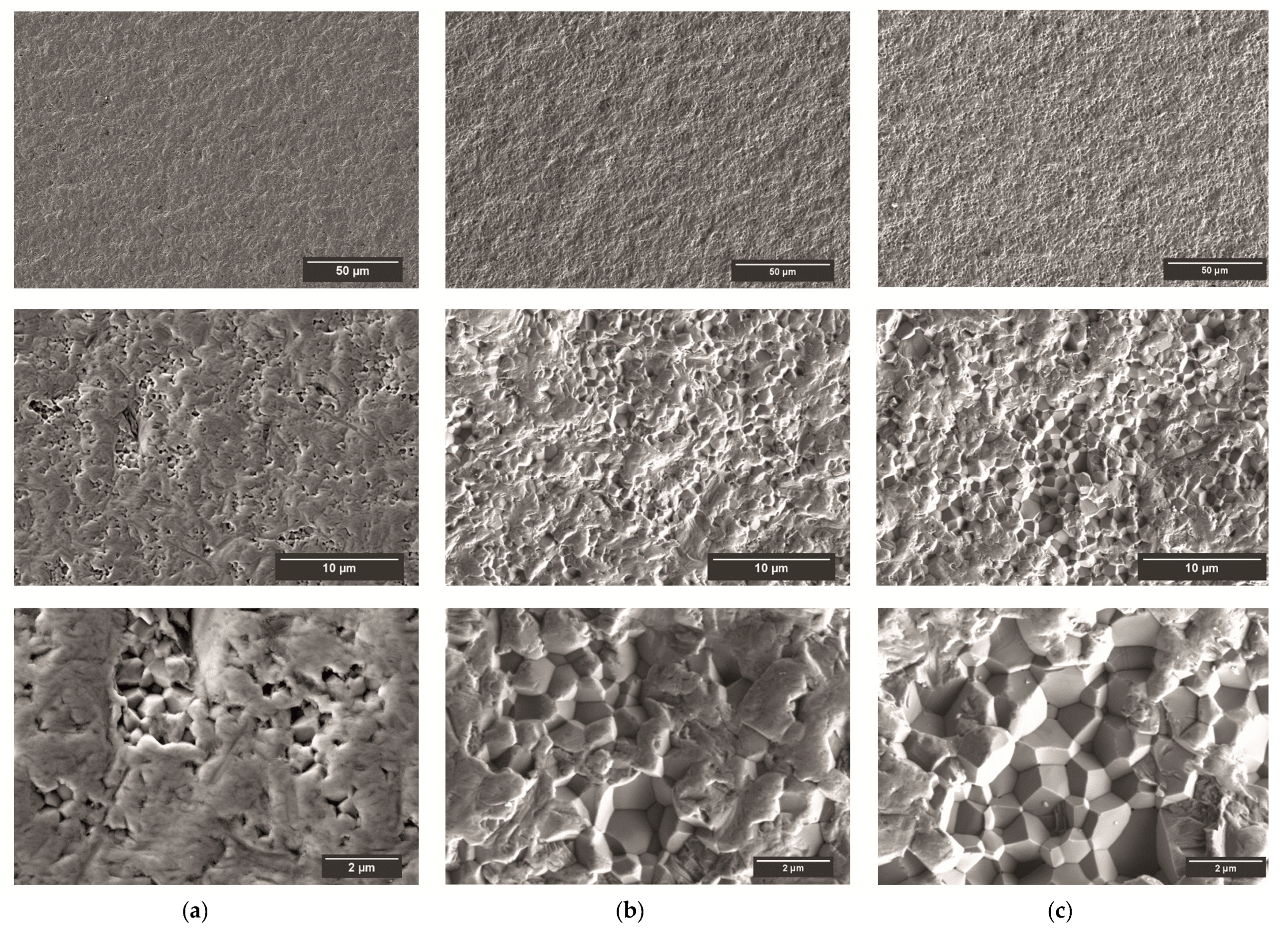
Figure 8 shows images of the as-cut surfaces of the O1, HT1350, and HT1400 substrates. The surface morphology of the O1 sample is characterized by smooth areas, caused by trans-crystalline fracture (Figure 8a). With increasing grain size of the ceramic, the surface morphology of the sawn substrate surface changes. With increasing grain size, the area of inter-crystalline fracture or grain breakout increases (Figure 8b,c).
The changed surface morphology of the substrates is also documented in the increased roughness values (Table 2, Figure 8a,b) and the decreased biaxial strength (Table 2). The roughness measurements parallel (R ||) and perpendicular to the wire movement direction (R ⊥) show no significant differences (Table 2). Therefore, the mean values include the values of both directions. The O1 substrates have a Ra-value of 0.23 ± 0.01 µm whereas the HT1350 substrates have a Ra-value of 0.33 ± 0.06 and HT1400 0.33 ± 0.02 µm (Figure 9a). The Rz -value increases from 1.65 ± 0.09 µm (O1) to 2.92 ± 0.58 µm (HT1400) (Figure 9b).
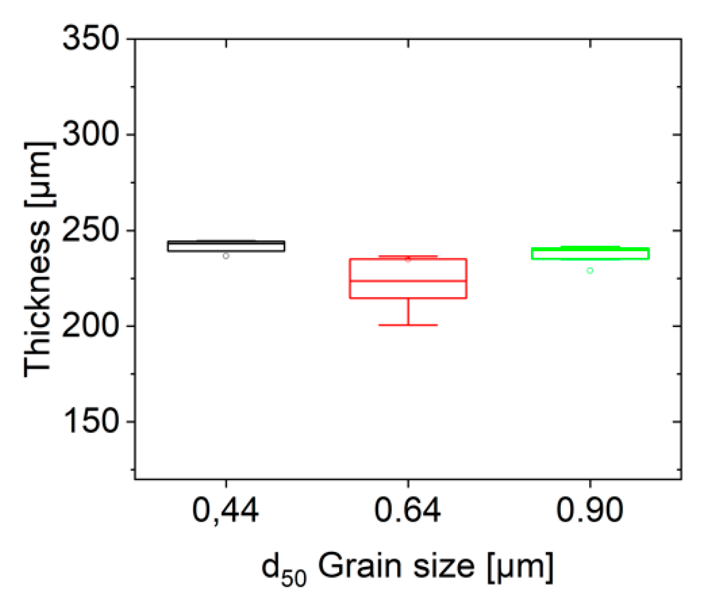
The substrates of O1 (cut #1, d50 alumina grain size: 0.44 µm) have a thickness variation of 237 ± 15 µm, the substrates of HT1350 (cut #3, d50 alumina grain size: 0.64 µm), have a thickness variation of 235 ± 38 µm and the HT1400 substrates (cut #2, d50 alumina grain size: 0.90 µm) have a thickness variation of 229 ± 25 µm (Figure 10). The increasing thickness variation with the number of cuts is caused by the wear of the abrasive grains and increasing portion of debris and the wider grain size distribution of the B4C abrasives after the re-dosing of fresh abrasives into the slurry-tank bevor cut #3.
4. Discussion
4.1. Relationship of Grain Coarsening and Efficiency of the Multi-Wire Sawing Process
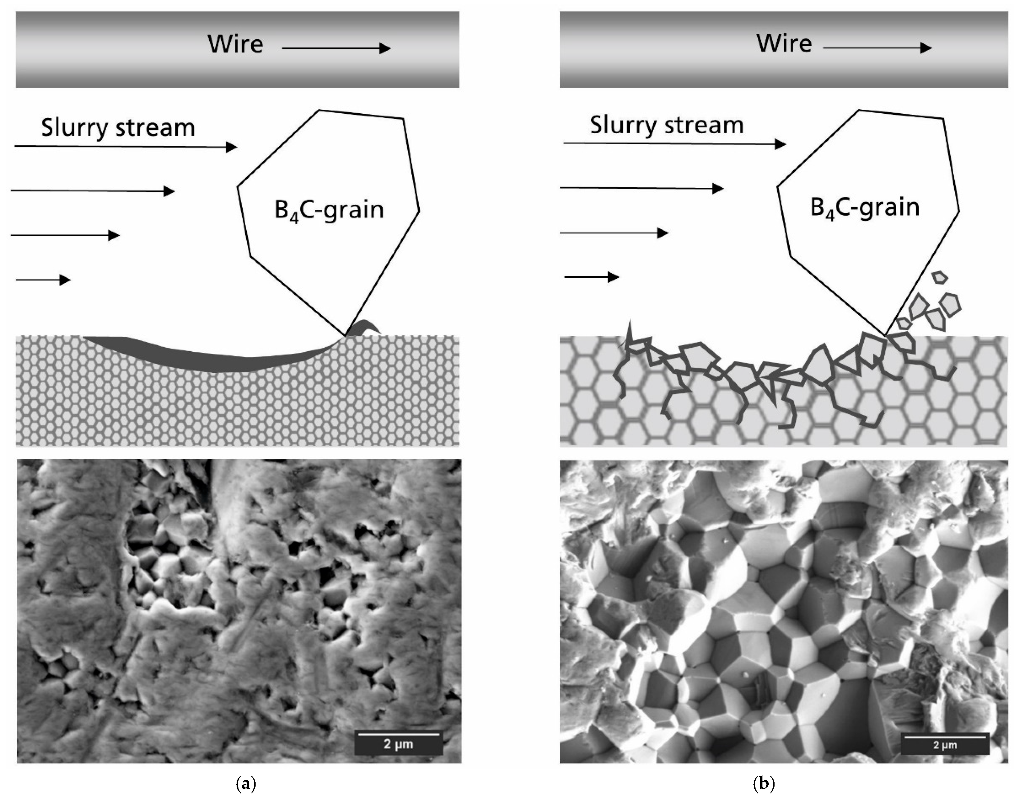
The cutting mechanism of multi-wire slurry sawing has been studied for silicon [14] and other hard and brittle materials such as quartz, glass, and ceramics [15] and can be described with the rolling indenting model. It states that the rolling abrasive particles in the sawing channel press onto the workpiece and cause elastic plowing (saw marks) or micro-fracture (chipping), schematically shown in Figure 11. The material properties such as the elastic modulus, hardness, and fracture toughness of the workpiece determine the elastic plowing or the chipping volume/shape, and thus the surface morphology of the substrates and the cutting rate.
The FESEM-analysis of the as-cut surface morphology of the substrates shows a transition from dominantly trans- to intergranular material removal with grain coarsening (Figure 8). The substrate surface of the original material is characterized by areas of trans-granular micro-fractures (saw marks) caused by elastic plowing (Figure 11a). This wear mechanism is also referred to as deformation-controlled material removal in other wear studies of alumina [16,17]. In contrast, the substrate surface of grain coarsened substrates is characterized by areas of inter-crystalline micro-fractures (grain boundary fracture) caused by chipping. This wear/cutting mechanism is referred to as fracture-controlled material removal (Figure 11b). A shift in the cutting mechanism is not analyzed in detail, but the surface morphology of the O1-substrates (Figure 8a) appears to be generated by ductile material removal [18]. The surface morphology of HT1350- and HT1400-substrates corresponds to brittle material removal.
The transition from deformation- to fracture-controlled wear of alumina ceramics, is characterized by an increased wear rate [16,17,18,19]. A simplistic fracture mechanics model, describes the phenomenon, that the wear-damage-induced stress levels required to cause intergranular micro-fracture in alumina ceramics decrease with increasing grain size [19], which reduces the wear resistance of the material. The wear experiments (reversing sliding abrasion performed with a rotating sphere on flat specimen) on which this model is based were conducted at local loads of approx. 3 GPa (the Hertzian stresses were estimated by the material and geometrical data given in the publication). The stresses of contact in slurry wire-sawing (free abrasive machining with third body particles) were modeled for cutting silicon with SiC abrasives [20] and the compression stresses underneath the indentation point are about 1–3 GPa depending on the exact shape of the indenting grain. Because of the comparable local stresses, the analogous wear behavior of the alumina ceramic is assumed for the multi-wire slurry sawing process. The fracture mechanics model [19] states that the reason for the reduced wear resistance of the grain coarsened samples is linked to the residual stresses in individual grains induced by the anisotropic thermal expansion. The micro-fracture from anisotropic thermal expansion of Al2O3-single-phase polycrystals is described in detail [17,19,21,22]. The c-axes of the alumina grains are under tensile stresses and the axes perpendicular to the c-axis are under compression stresses. Some silicate grain boundary phase reduces these stresses. The influence of the grain size on the residual stresses is marginal, but due to the grain size-dependent creep behavior, a different relaxation behavior can be observed during cooling.
An increase in the cutting efficiency results from the grain coarsening of the alumina ceramic and the resulting change in the removal mechanism from dominantly trans- to intergranular. The efficiency of the multi-wire sawing process can be described by the size of the wire bow, the smaller the wire bow, the higher the sawing rate. Correction of the measured wire bow values was carried out, as the d50-B4C abrasive grain size varies due to wear in the sawing channel. The corrected data show a decrease in the wire bow size of −6.60 (±0.48) mm per µm increase of the d50-grain size of the alumina ceramic. This represents a significant improvement in the cutting rate of alumina ceramic substrates because the nominal cutting speed can be increased (>20 µm/min) to shorten the processing time. By decreasing the size of the wire bow, it has been shown that fracture-controlled material removal during multi-wire sawing is more efficient than deformation-controlled material removal. However, the surface damage by the process is not very pronounced. This can be proven by the slight change of strength.
Further studies on slurry wire-sawing of alumina ceramics have shown that increasing the sawing angle Ɵ from 0° to 25° and the use of ultrasound, perpendicular to the feed direction, increases the material removal rate [3]. In the field of diamond wire-sawing of alumina ceramics, it was found that an increased wire tension from 13.3 to 26.3 N (no influence on Ra-values), and an increased wire speed from 1.3 to 3.5 m/s (decrease in the Ra-values of 1.5–1.2 µm) increase the material removal rate and therefore reduce the size of the wire bow [23]. The results from both studies refer to single-wire sawing experiments. In the field of multi-wire silicon cutting with SiC abrasives similar results were made. A decrease in the feed rate and the working length reduce the size of the wire bow. A reduction of the size of the wire bow by increasing the material removal rate can be achieved by increasing the wire speed from 8 to 20 m/s, increasing the wire tension from 10 to 25 N, and increasing the slurry viscosity to 0.4 Ns/m2 [24].
4.2. Quality of the Ceramic Substrates
Due to the microstructural modification of grain coarsening and the varied grit size distribution of the B4C d50-abrasives in the slurry-tank, the substrate properties change. With grain coarsening a transition from trans- to intergranular material removal is visible in an increase of the Ra- and Rz-values by 0.1 and 1.5 µm (Figure 9). In contrast to the measured roughness values, the variation in substrate thickness remains unaffected by the grain coarsening. A decrease in the biaxial strength from 1356 MPa (O1) to 1033 MPa (HT1400) and a decrease in the fracture toughness from 3.5 (O1) to 2.8 MPa*m0.5 (HT1400) is observed (Table 2). This is can be caused by various reasons. EDX-measurements show an increased size of MgO-rich-precipitations (size: 0.3–0.4 µm) at grain junctions and triple points with grain coarsening. Inhomogeneities in the microstructure can act as fracture initiating defects. Furthermore, an increase in the Ra- and Rz-values is measured, indicating the possibility of larger surface defects. Further B3B tests were performed to answer the question of whether the decrease in substrate strength is due to the different damages caused by the sawing process or the change in microstructure. O1- and HT1400-substrates were additionally polished to generate similar surfaces. 9 O1-substrates and 12 HT1400-substrates were tested. Due to the small number of samples, no Weibull analysis was conducted, and the mean value and standard deviation of the strength values are given. The polished O1 substrates have a strength of 1336 ± 234 MPa and the HT1400 substrates have a strength of 1453 ± 250 MPa. The strength of the polished O1 substrates is almost constant compared to the as-cut substrates, while the strength of polished HT1400 substrates is increased by about 400 MPa. It can be stated that the strength of the as-cut substrates is determined by the severity of surface damage caused by sawing.
5. Conclusions
The grain size of the HIPed alumina ceramics was changed by heat treatment processes at 1350 °C and 1400 °C from an initial d50-value of 0.44 µm to 0.64 µm and 0.90 µm. It was found that the Vicker’s hardness decreases by about 10% with increasing grain size. However, the sawing processes are significantly changed.
The efficiency of the multi-wire slurry process increases with increasing grain size of the alumina ceramics. The increasing sawing efficiency is visible by the decrease in the size of the wire bow of −6.60 (±0.48) mm per µm d50 alumina grain size in the investigated range of 0.44–0.90 µm. It was found that multi-wire slurry sawing of alumina with a d50 grain size ≥0.90 µm and without glassy phase can be performed at a feed rate >20 µm/min.
The increase in efficiency of the multi-wire slurry process is linked to a transition in the material removal mechanism. Field emission scanning electron microscopy (FESEM) analysis of the as-cut surface morphology shows a transition from trans- to intergranular material removal with grain coarsening. The transition from deformation controlled to fracture controlled wear is characterized by an increased wear rate. However, this results only in a moderate change in the properties of the substrate.
An increase of the Ra- and Rz-value by 0.1 and 1.5 µm of the substrates is observed due to the grain coarsening. The biaxial strength changes from 1356–1033 MPa. To answer the question of whether the decrease in substrate strength is due to sawing or the change in microstructure, further B3B tests on polished O1 and HT1400 substrates were performed. The strength of the polished O1 substrates is almost constant compared to the as-cut substrates, while the strength of polished HT1400 substrates is increased. The strength of substrates is determined by the severity of surface damage caused by sawing.
In summarizing the experiments, it can be concluded that the multi-wire sawing is an interesting technology for cutting high-performance ceramics. However, the process depends on the cutting parameter and the microstructure. Further detailed investigations of the influence of residual porosity, amount, and nature of the glassy phase under the different cutting conditions have to be performed to establish this method. A compromise between the sawing performance and the quality requirements of the substrates can be freely adjusted according to the application.
Author Contributions
L.S. and M.H.; methodology, L.S. and M.H.; validation, M.H. and C.G.A.; formal analysis, L.S.; investigation, L.S. and M.H.; Methodology, L.S. and M.H.; Project administration, M.H. and C.A.; resources, M.H.; data curation, L.S.; writing—original draft preparation, L.S.; writing—review and editing, M.H. and C.G.A.; visualization, L.S.; supervision, M.H. and C.G.A.; All authors have read and agreed to the published version of the manuscript.
Funding
This research received no external funding.
Acknowledgments
The authors would like to thank H. Heinrich for operating the multi-wire saw as well as I. Graf for sample preparation and M. Berger and U. Körber for additional measurements.
Conflicts of Interest
The authors declare no conflict of interest.
References
- Miric, A.; Dietric, P. Inorganic substrates for power electronics applications. Dvs-Ber. 2015, 310, 63–73. [Google Scholar]
- Kita, J.; Schubert, F.; Rettig, F.; Engelbrecht, A.; Groß, A.; Moos, R. Ceramic Alumina Substrates for High-temperature Gas Sensors—Implications for Applicability. Procedia Eng. 2014, 87, 1505–1508. [Google Scholar] [CrossRef] [Green Version]
- Hsu, Y.; Chen, S.; Tsao, C. Free abrasive wire saw machining of ceramics. Int. J. Adv. Manuf. Technol. 2009, 40, 503–511. [Google Scholar] [CrossRef]
- Theophil, L. Anpassung der Diamantdrahtsägeprozesse für eine Bessere Texturierfähigkeit von Multikristallinen Siliziumwafern. Master’s Thesis, TU Freiberg, Freiberg, Saxony, Germany, 2019. [Google Scholar]
- Gehl, E. Untersuchung der Topografie und Oberflächenschädigung an Siliziumwafern, die mit Unterschiedlichen Kühlschmierstoffen und Prozessparametern Hergestellt Wurden. Bachelor’s Thesis, TU Freiberg, Freiberg, Saxony, Germany, 2014. [Google Scholar]
- Schmidtner, L.; Heinrich, H.; Fuchs, M.; Pötzsch, A.; Janz, S.; Herrmann, M.; Aneziris, C.; Kaden, T. Multi-Wire Sawing of Translucent Alumina Ceramics. J. Manuf. Mater. Process. 2020, 4, 2. [Google Scholar] [CrossRef] [Green Version]
- Bidiville, A.; Wasmer, K.; Michler, J.; Nasch, P.M.; Van der Meer, M.; Ballif, C. Mechanisms of wafer sawing and impact on wafer properties. Prog. Photovolt. Res. Appl. 2010, 18, 563–572. [Google Scholar] [CrossRef]
- Munz, D.; Fett, T. Mechanical Properties, Failure Behaviour, Materials Selection; Springer: Berlin/Heidelberg, Germany, 1999; p. 36. [Google Scholar]
- Börger, A.; Supancic, P.; Danzer, R. The ball on three balls test for strength testing of brittle discs: Stress distribution in the disc. J. Eur. Ceram. Soc. 2002, 22, 1425–1436. [Google Scholar] [CrossRef]
- Danzer, R.; Harrer, W.; Supancic, P. Ein einfacher Festigkeitsversuch für Scheiben aus spröden Werkstoffen. Mater. Und Werkst. 2003, 34, 490–498. [Google Scholar] [CrossRef]
- Franken, P.; Gehring, A. Grain boundary analysis of MgO-doped Al2O3. J. Mater. Sci. 1981, 16, 384–388. [Google Scholar] [CrossRef]
- Krell, A. The effects of load, grain size, and grain boundaries on the hardness of alumina. Ceram. Eng. Sci. Proc. 1998, 19, 159–168. [Google Scholar]
- Yip, S. The strongest size. Nature 1998, 391, 532–533. [Google Scholar] [CrossRef]
- Möller, H.J. Basic Mechanisms and Models of Multi-Wire Sawing. Adv. Eng. Mater. 2004, 6, 501–513. [Google Scholar] [CrossRef]
- Yang, F.; Kao, I. Free Abrasive Machining in Slicing Brittle Materials with Wiresaw. J. Electron. Packag. 2001, 123, 254–259. [Google Scholar] [CrossRef]
- Zum Gahr, K.; Telle, R.; Zimmerlin, B.; Park, S. Einfluß der Korngröße auf mechanische Eigenschaften und den ungeschmierten reversierenden Gleitverschleiß von Al2O3-Keramik. Mater. Sci. Eng. Technol. 1992, 23, 329–338. [Google Scholar]
- Mukhopadhyay, A.; Chakraborty, D.; Swain, M.; Mai, Y. Scratch deformation behaviour of alumina under a sharp indenter. J. Eur. Ceram. Soc. 1997, 17, 91–100. [Google Scholar] [CrossRef]
- Cho, S.; Moon, H.; Hockey, B.J.; Hsu, S.M. The transition from mild to severe wear in alumina during sliding. Acta Metall. Mater. 1992, 40, 185–192. [Google Scholar] [CrossRef]
- Cho, S.; Hockey, B.; Lawn, B.; Bennison, S. Grain-Size and R-Curve Effects in the Abrasive Wear of Alumina. J. Am. Ceram. Soc. 1989, 72, 1249–1252. [Google Scholar] [CrossRef]
- Li, J.; Kao, I.; Prasad, V. Modeling Stresses of Contacts in Wire Saw Slicing of polycrystalline and crystalline ingots—Application to Silicon Wafer Production. J. Electron. Packag. 1998, 120, 123–128. [Google Scholar] [CrossRef]
- Michalowsky, L. Neue keramische Werkstoffe; Deutscher Verlag für Grundstoffindustrie Leipzig: Stuttgart, Germany, 1994; pp. 317–319. [Google Scholar]
- Evans, A. Microfracture from thermal expansion anisotrpy-I. Single phase systems. Acta Metall. 1978, 26, 1845–1853. [Google Scholar] [CrossRef]
- Teomete, E. Roughness damage evolution due to wire saw process. Int. J. Precis. Eng. Manuf. 2011, 66, 941–947. [Google Scholar] [CrossRef]
- Liedke, T.; Kuna, M. A macroscopic mechanical model of the wire sawing process. Int. J. Mach. Tools Manuf. 2011, 9, 711–720. [Google Scholar] [CrossRef]
Figure 1.
Wire guide rollers; 2: Fresh wire; 3: Wire web; 4: Workpiece; 5: Top plate; 6: Slurry nozzles; 7: Used wire [5].
Figure 1.
Wire guide rollers; 2: Fresh wire; 3: Wire web; 4: Workpiece; 5: Top plate; 6: Slurry nozzles; 7: Used wire [5].
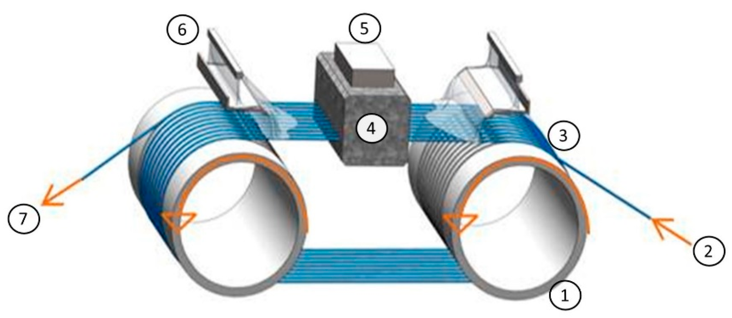
Figure 2.
Wire bow (length); 2: Feed direction; 3: Compact part of the workpiece; 4: Processed part of the workpiece [6].
Figure 2.
Wire bow (length); 2: Feed direction; 3: Compact part of the workpiece; 4: Processed part of the workpiece [6].

Figure 3.
Field emission scanning electron microscopy (FESEM) images of the polished cross section of the sample: (a) O1 [6]; (b) HT1350; (c) HT1400.
Figure 3.
Field emission scanning electron microscopy (FESEM) images of the polished cross section of the sample: (a) O1 [6]; (b) HT1350; (c) HT1400.
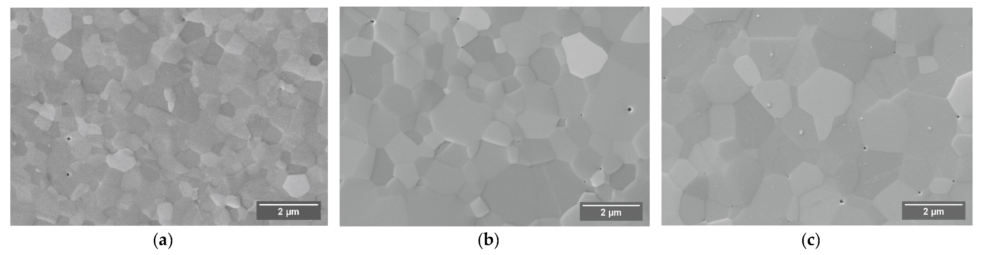
Figure 4.
Overlay of Mg distribution (EDX, violet color) and electron image of the polished cross section of the sample: (a) O1; (b) HT1400 (different magnifications were used due to the different grain sizes of the samples).
Figure 4.
Overlay of Mg distribution (EDX, violet color) and electron image of the polished cross section of the sample: (a) O1; (b) HT1400 (different magnifications were used due to the different grain sizes of the samples).
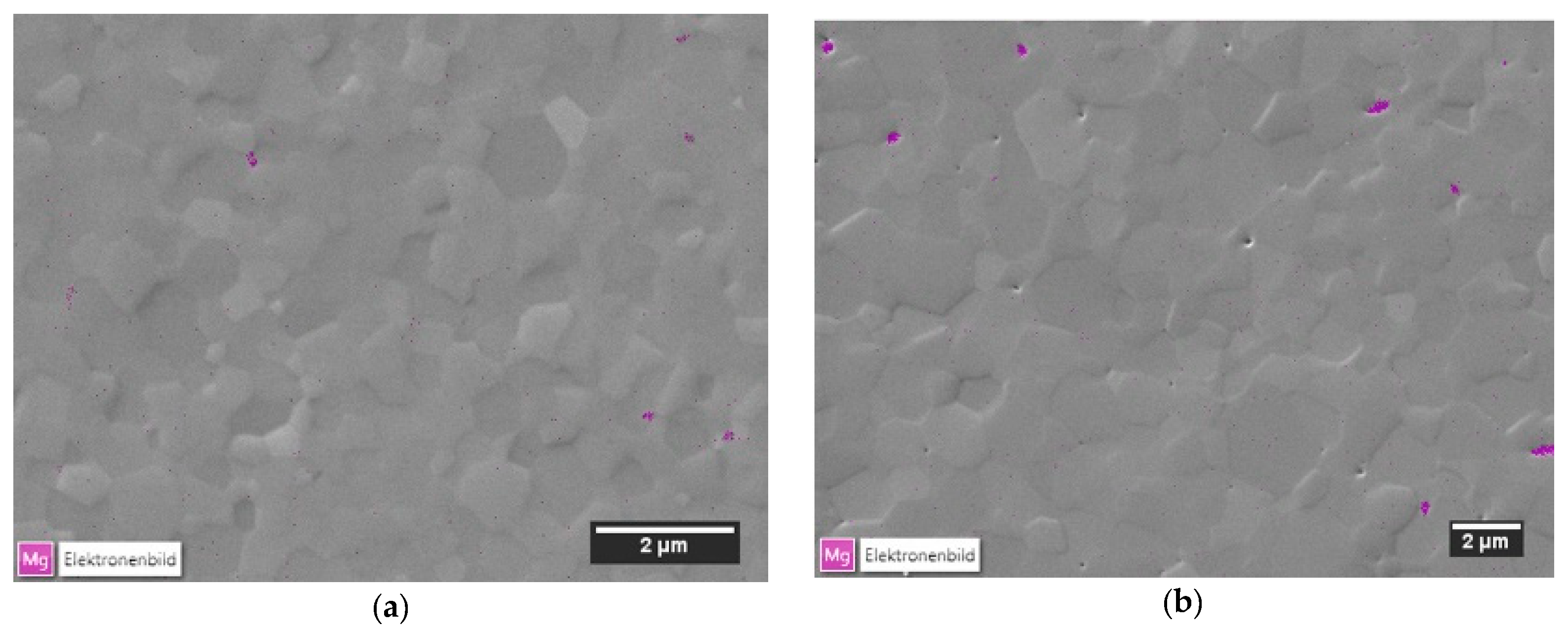
Figure 5.
Influence of the heat treatment temperature on the grain size of alumina ceramic.
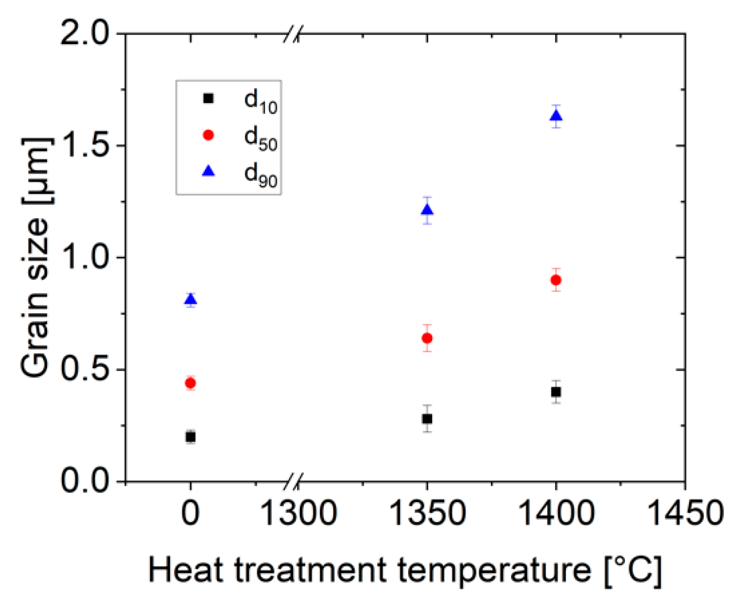
Figure 6.
Influence of the alumina grain size on the hardness of the sample.

Figure 7.
Influence of the alumina ceramic grain size on the size of the wire bow; regression of original data: −4.09 (±0.48) × +4.38 (±0.33); COD (r2): 0.98; regression of the corrected data = −6.60 (±0.48) × +5.63 (±0.33); COD (r2): 0.99).
Figure 7.
Influence of the alumina ceramic grain size on the size of the wire bow; regression of original data: −4.09 (±0.48) × +4.38 (±0.33); COD (r2): 0.98; regression of the corrected data = −6.60 (±0.48) × +5.63 (±0.33); COD (r2): 0.99).

Figure 8.
Field emission scanning electron microscopy (FESEM) images of the as-cut substrate surfaces of the sample: (a) O1; (b) HT1350; (c) HT1400.
Figure 8.
Field emission scanning electron microscopy (FESEM) images of the as-cut substrate surfaces of the sample: (a) O1; (b) HT1350; (c) HT1400.

Figure 9.
Surface roughness parameters measured on the substrates of O1, HT1350 and HT1400 with different d50-grain sizes (a) Ra; (b) Rz.
Figure 9.
Surface roughness parameters measured on the substrates of O1, HT1350 and HT1400 with different d50-grain sizes (a) Ra; (b) Rz.

Figure 10.
Thickness variation of the substrates of O1, HT1350 and HT1400 for different d50-grain sizes.
Figure 10.
Thickness variation of the substrates of O1, HT1350 and HT1400 for different d50-grain sizes.

Figure 11.
Cutting mechanisms in the multi-wire slurry process for Al2O3-ceramics; (a) deformation-controlled material removal (trans-granular) for fine grained Al2O3; (b) fracture-controlled material removal (inter-granular) for coarse grained Al2O3.
Figure 11.
Cutting mechanisms in the multi-wire slurry process for Al2O3-ceramics; (a) deformation-controlled material removal (trans-granular) for fine grained Al2O3; (b) fracture-controlled material removal (inter-granular) for coarse grained Al2O3.


Table 1.
Common process parameters.
| Sawing Parameters | |
|---|---|
| Wire condition | New |
| Wire speed (m/s) | 14 |
| Wire tension (N) | 25 |
| Pitch (mm) | 0.425 |
| Number of substrates cut in one process | 17 |
| Wire nominal diameter (mm) | 0.115 |
| Nominal B4C abrasive size (µm) | 8–32 |
| Table feed rate (mm/min) | 0.02 |
| B/F ratio | 0.64 |
Table 2.
Mechanical properties of the original and grain coarsened Al2O3-ceramics.
| Original | Heat Treatment 1 | Heat Treatment 2 | |
|---|---|---|---|
| Process | HIP Al2O3 | HIP Al2O3 | HIP Al2O3 |
| Sample name | O1 | HT1350 | HT1400 |
| Additional heat treatment temperature (°C) | - | 1350 | 1400 |
| Density (g/cm3) | 3.98 ± 0.01 | 3.98 ± 0.01 | 3.98 ± 0.01 |
| Grain size d50-value (µm) | 0.44 ± 0.03 | 0.64 ± 0.06 | 0.90 ± 0.05 |
| Vicker’s hardness | |||
| HV0.5 | 2279 ± 1 | 2139 ± 23 | 2142 ± 23 |
| HV1 | 2220 ± 5 | 2060 ± 18 | 2027 ± 25 |
| HV2 | 2168 ± 13 | 2059 ± 23 | 1980 ± 15 |
| KIC (Niihara HP; HV1) (MPa*m0.5) | 3.5 ± 0.2 | 3.4 ± 0.1 | 2.8 ± 0.2 |
| Characteristic biaxial strength of the cut substrates (Mpa) | 1356 (1328‒1386) | 1144 (1116‒1173) | 1033 (1008–1059) |
| Weibull modulus | 16.3 ± 3.5 | 14.2 ± 4.0 | 14.0 ± 3.0 |
| Surface roughness of the cut substrates | |||
| Ra ⊥ (µm) | 0.23 ± 0.01 | 0.32 ± 0.03 | 0.33 ± 0.02 |
| Ra || (µm) | 0.23 ± 0.01 | 0.36 ± 0.08 | 0.33 ± 0.02 |
| Rz ⊥ (µm) | 1.70 ± 0.09 | 2.04 ± 0.53 | 3.00 ± 0.54 |
| Rz || (µm) | 1.62 ± 0.09 | 2.18 ± 0.50 | 2.84 ± 0.62 |
© 2020 by the authors. Licensee MDPI, Basel, Switzerland. This article is an open access article distributed under the terms and conditions of the Creative Commons Attribution (CC BY) license (http://creativecommons.org/licenses/by/4.0/).
Share and Cite
MDPI and ACS Style
Schmidtner, L.; Herrmann, M.; Aneziris, C.G. Grain-Size Effects on Multi-Wire Slurry Sawing of Translucent Alumina Ceramics. Ceramics 2020, 3, 428-439. https://0-doi-org.brum.beds.ac.uk/10.3390/ceramics3040036
AMA Style
Schmidtner L, Herrmann M, Aneziris CG. Grain-Size Effects on Multi-Wire Slurry Sawing of Translucent Alumina Ceramics. Ceramics. 2020; 3(4):428-439. https://0-doi-org.brum.beds.ac.uk/10.3390/ceramics3040036
Chicago/Turabian StyleSchmidtner, Lea, Mathias Herrmann, and Christos G. Aneziris. 2020. "Grain-Size Effects on Multi-Wire Slurry Sawing of Translucent Alumina Ceramics" Ceramics 3, no. 4: 428-439. https://0-doi-org.brum.beds.ac.uk/10.3390/ceramics3040036