
Highly Efficient Small Anode Ion Source


1
Muons, Inc., 552 North Batavia Ave. Batavia, IL 605101, USA
2
Budker Institute of Nuclear Physics, 630090 Novosibirsk, Russia
*
Author to whom correspondence should be addressed.
Plasma 2021, 4(2), 214-221; https://0-doi-org.brum.beds.ac.uk/10.3390/plasma4020013
Submission received: 19 February 2021
/
Revised: 11 March 2021
/
Accepted: 23 March 2021
/
Published: 25 March 2021
(This article belongs to the Special Issue Low Temperature Plasmas for Ion Beam Generation)
Abstract
:We describe some modifications to a Bernas-type ion source that improve the ion beam production efficiency and source operating lifetime. The ionization efficiency of a Bernas type ion source has been improved by using a small anode that is a thin rod, oriented along the magnetic field. The transverse electric field of the small anode causes the plasma to drift in the crossed ExB field to the emission slit. The cathode material recycling was optimized to increase the operating lifetime, and the wall potential optimized to suppress deposition of material and subsequent flake formation. A three-electrode extraction system was optimized for low energy ion beam production and efficient space charge neutralization. An ion beam with emission current density up to 60 mA/cm2 has been extracted from the modified source running on BF3 gas. Space charge neutralization of positive ion beams was improved by injecting electronegative gases.
1. Introduction
A review of ion source development for ion implantation and isotope separation has been well described elsewhere [1]. The Bernas–White ion source (BWIS) is now the most widely used in high current ion implanters [1], and several versions of BWIS are manufactured by some industrial companies [2]. Somewhat more complicated versions of BWIS with two filaments or indirectly heated cathodes have been used for high current and multicharged ion beam production [3,4]. However, yet further improvements of the ion beam parameters and increased ion source lifetime are necessary for advanced ion implanters. Here we describe some modifications to a Bernas-type ion source that improve the ion beam production efficiency and source operating lifetime.
2. Small Anode Ion Source: Discharge Configuration
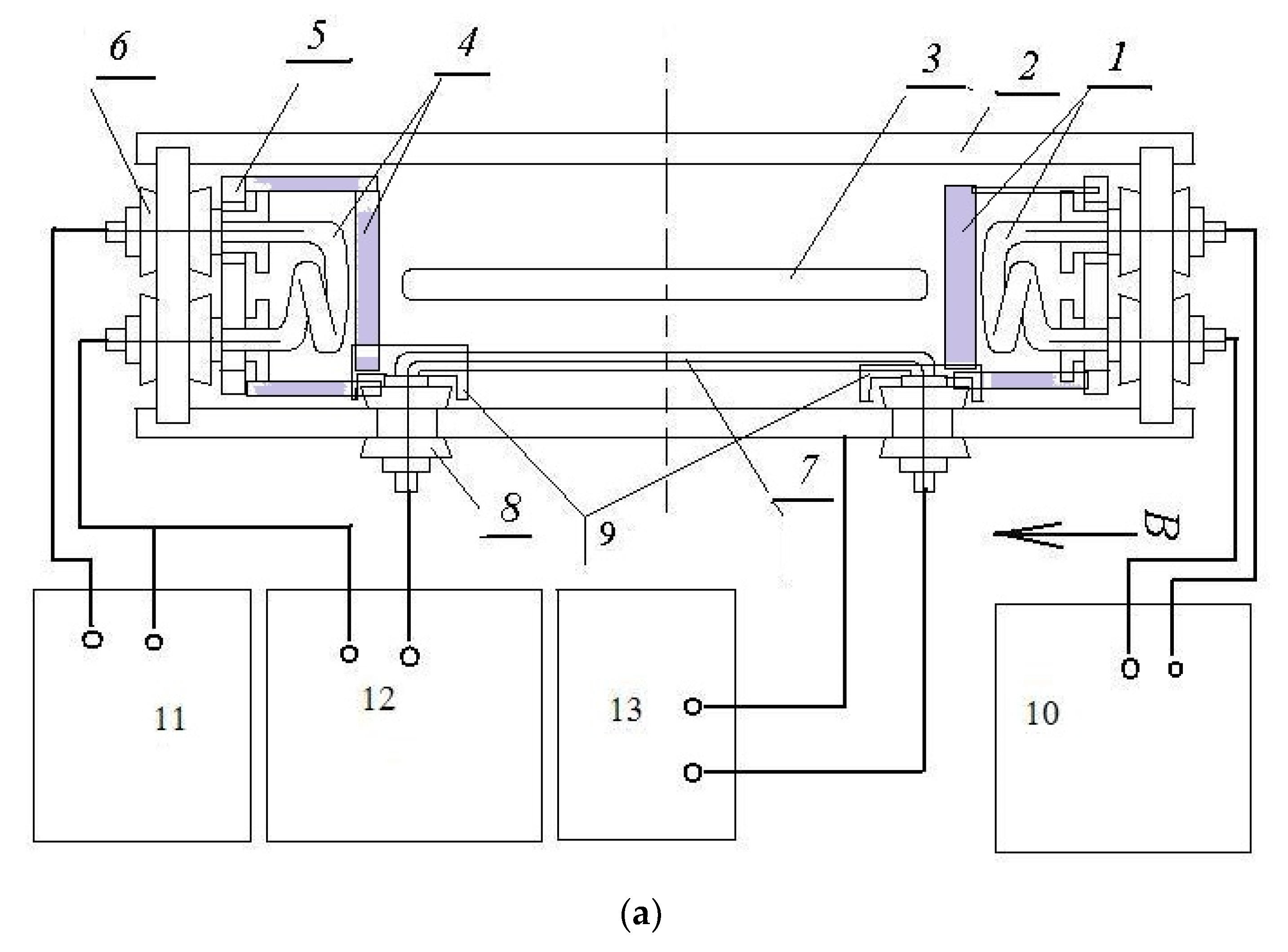
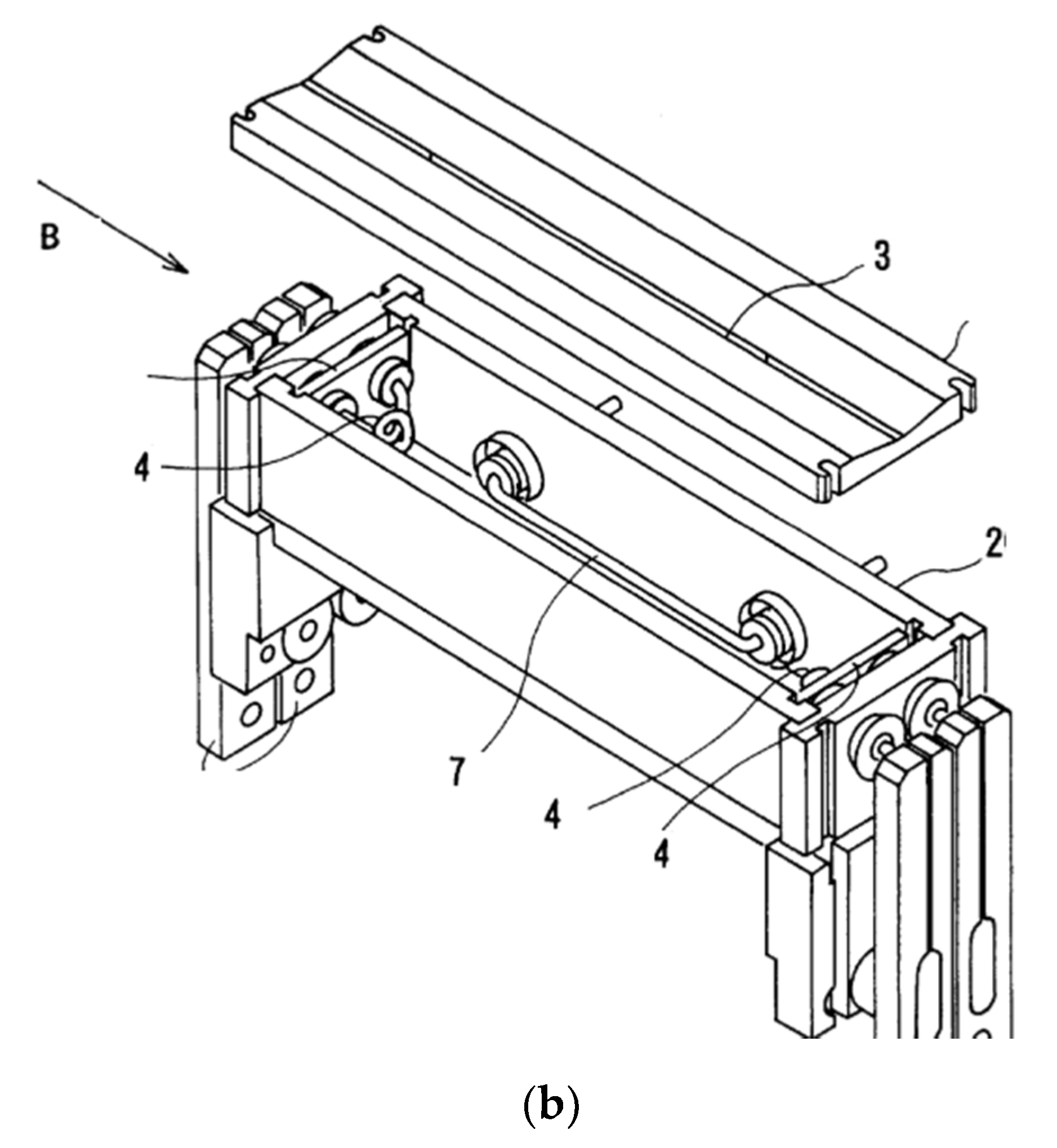
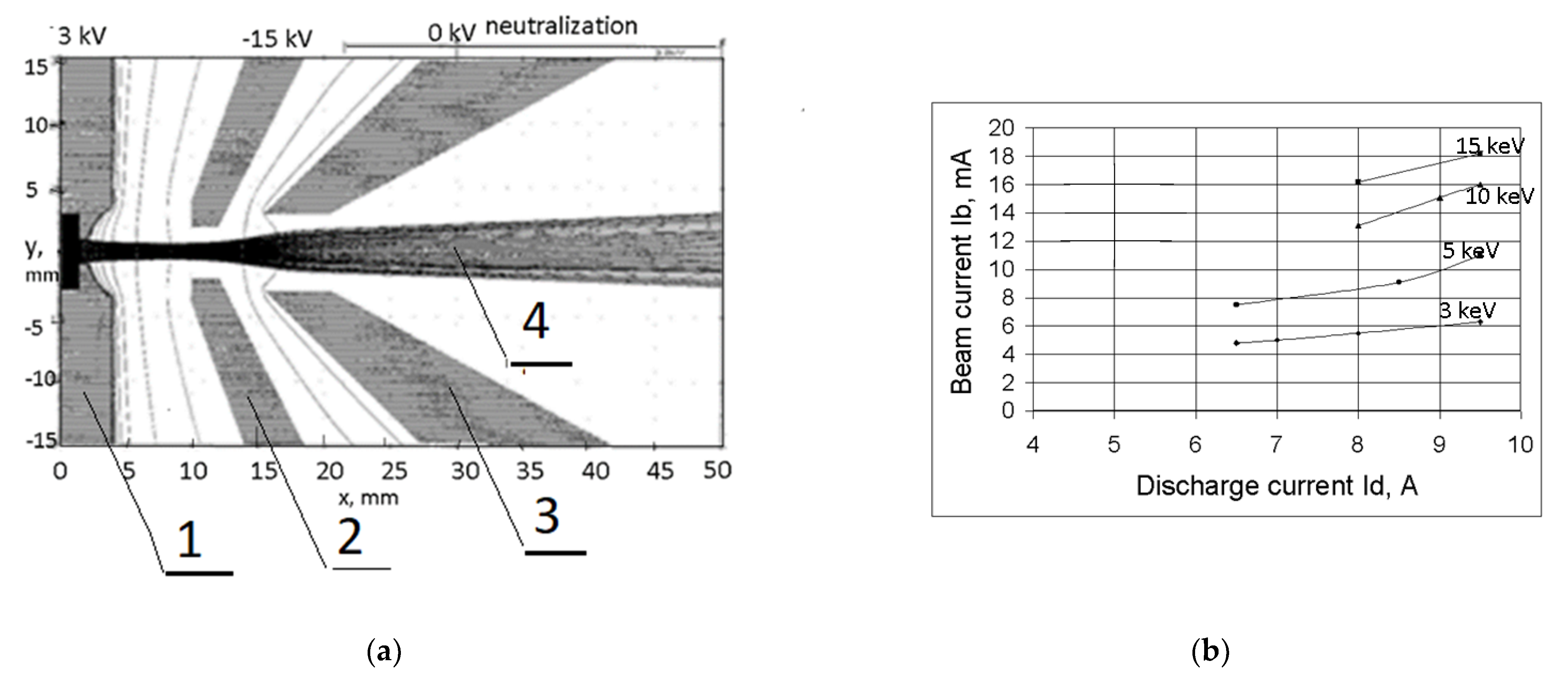
We describe here some modifications to the ion source that improve beam production efficiency and source operating lifetime [5,6]. We have improved the ionization efficiency of a Bernas type ion source by using a small anode that is a thin rod, oriented along the magnetic field. A magnetic field of ~400 Gauss is created by an electromagnet and oriented along the axis of the ion source. The transverse electric field of the small anode causes the plasma to drift in the crossed ExB direction towards the emission slit. The design of our small anode ion source (SAS) is shown in Figure 1. It consists of an anode body 2, cathodes 1 and 4, cathode insulators 6, chamber cover with emission slit 3, small anode (SA) 7, small anode insulators 8, and insulator screens 9. The discharge is supported by a voltage applied between cathodes 1 and, 4 and the small anode 7, which is made from 2.4 mm diameter tungsten wire (as filaments) of 50 mm length and supported by ceramic (filament) insulators 8 in the middle part of the left sidewall of the discharge chamber. In later experiments, the small anode (SA) supporting insulators were shielded from filament vapors by disks 9. The transverse electric field of the small anode penetrates into the magnetized plasma, which is transported by ExB drift to the emission slit 3 and, thus, increases the emission current density. Cathode material recycling is optimized so as to increase the operating lifetime. The wall potential is optimized to suppress flake formation. Different versions of insulators and shielding for the small anode were tested. The three-electrode extraction system is shown in Figure 2a; it is optimized for low energy beam production and efficient space charge neutralization. The best material for the extractor was found to be graphite. Design and optimization of the extraction geometry were done using the relaxation code PBGUNS developed by Jack Boers of Thunderbird Simulations, Texas [7]. This code, which has been well tested, simultaneously relaxes the shape of the meniscus at the plasma boundary to include the effects of plasma density together with the effects of space charge within the beam as the extracted ions accelerate through the extraction region. Space charge neutralization at the 99% level is assumed beyond the suppressor electrode. The extractor electrodes can be moved to optimize beam formation at different energies. The measured dependence of the analyzed 11B+ beam current on discharge current for different beam energies is shown in Figure 2b. A similar approach to ours has been proposed in [8].
Ion beams with emission current density up to 60 mA/cm2 have been extracted from this source operating with BF3 gas. 11B+ ion beams with intensity up to 6 mA at 3 keV, 11 mA at 5 keV, 16 mA at 10 keV, and 18 mA at 15 keV have been transported through the analyzer magnet of the experimental implanter shown in Figure 3; see Figure 2b.
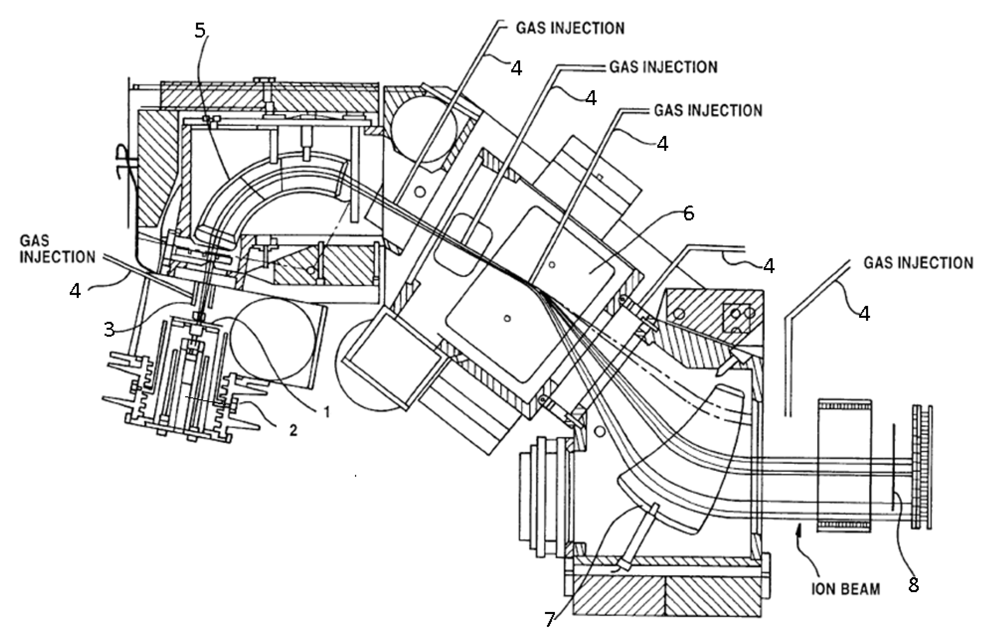
The experimental implanter (Figure 3) for testing our small anode ion source consists of the ion source 2, with extractor 1, tunnel 3, gas injectors 4, strong focusing analyzing magnet 5, scanning magnet 6, collimating magnet 7, and wafer holder 8. Magnetic analysis is used to remove undesired impurities according to the ion momentum to charge ratio (MV/Z, where V is the ion velocity, Z the ion charge, and M the ion mass). Scanner magnet 6 then scans the ion beam in a direction perpendicular to the beam path. Following scanning, collimator magnet 7 reorients the ion beam such that the beam is parallel over the entire scan area. This implanter is similar to the Purion implanter manufactured by Axcelis [9].
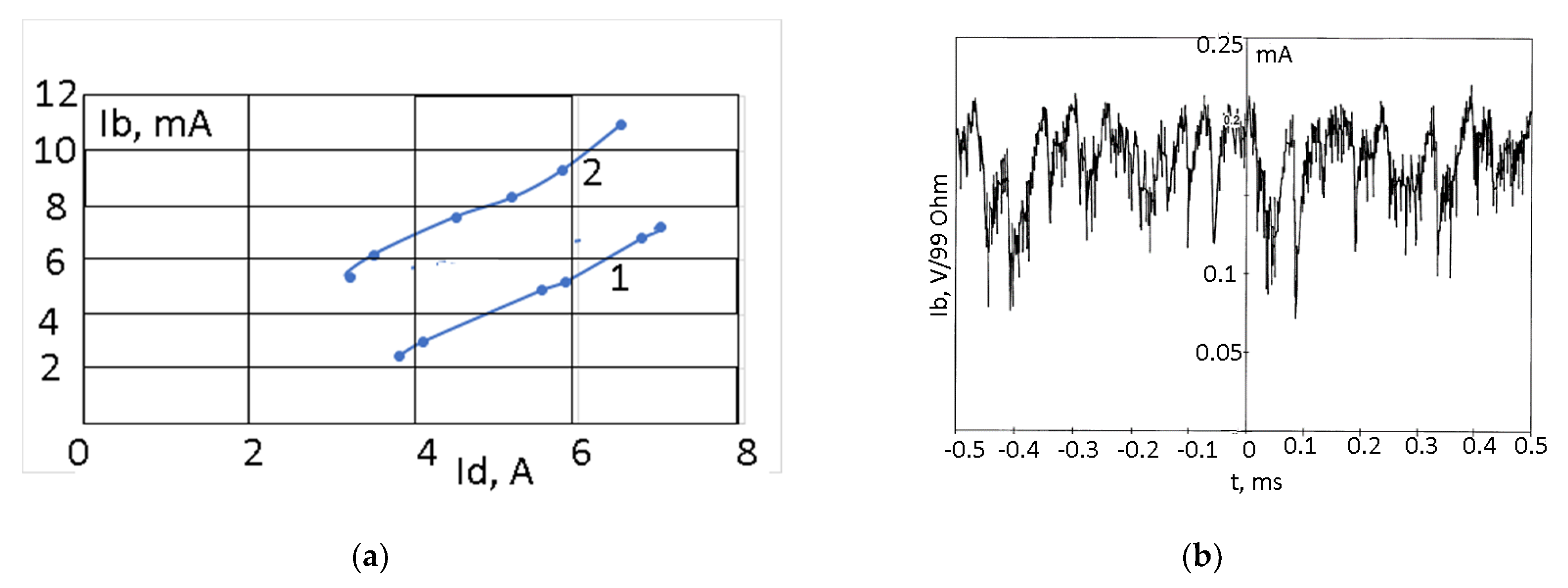
A comparison of the dependence of the 11B+ ion beam current on discharge current for our small anode ion source (curve 2) and for the Bernas design (curve 1) is shown in Figure 4a. The beam intensity of our small anode source is greater than that of the Bernas–White source by about a factor of two. Further, the lifetime of the small anode source is up to 5 times greater than that of the Bernas–White source [1]. The Bernas–White source produces ~6 mA B+ ions with a typical lifetime of about 80 h [1], compared to the lifetime of about 400 h for the SAS at this same this current.
3. Improving the Space Charge Compensation of Positive Ion Beams by Negative Ions
Space charge compensation (SCC) (also called space charge neutralization) of positive ion beams by negative ions and stabilization of beam plasma instabilities by negative ions have been described [10,11,12,13,14]. In almost all previous investigations of SCC of positive ion beams it has been assumed that the compensating particles are electrons [15]. However, in the environment of isotope separation and ion implantation where complex halide and hydride molecules with high electron affinity are often used as working gases, there is a high probability of negative ion formation. In this situation, SCC by negative ions can be significant. Indeed, SCC by negative ions can be the determining factor in large scale ion beam industries, but so far this circumstance has not been investigated.
We have explored the possibility of improving SCC by negative ions utilizing the beam line shown in Figure 3, with magnetic suppression of secondary electrons in the beam after the mass analyzer. For production of high perveance ion beams, an ion source with two cathodes and small anode made from W wire was used. A three-electrode extraction system made from high density graphite with precision moving electrodes was used for beam formation. For low energy beam extraction, the suppressor electrode was biased to high voltage (up to −20 kV for 3 keV ion energy). Production of high energy neutrals and negative ions in the extractor gap and on the suppressor surface is important for enhancing residual gas ionization and improving the space charge neutralization. In the “standard” operational mode with strong acceleration-deceleration, for low gas density and low discharge current, the post-analysis ion beam typically displays significant noise (fluctuation level of beam current), as shown in Figure 4b. The beam intensity increases up to a critical level, beyond which beam instability occurs, leading to loss of SCC and a drop of intensity, and then this cycle repeats. The main frequency of these oscillations is ~20 kHz. However, we have found that with electronegative gases in the ion source, such as BF3 or CF4, it is possible to suppress the beam instability by increasing the gas injection into the source. Note that beam instability (beam noise) was not suppressed by increase of noble gas density, such as Ar or Kr. Improved SCC and damping of instabilities is related to the addition of negative ions into the beam instead of free electrons.
To enhance negative ion formation in the ion beam, we have injected electronegative heavy molecules with high electron affinity into the beam. Negative ions in the beam are formed by collision of electrons with molecules and by bombardment of electrode surfaces by beam and plasma particles [16,17,18]. With the use of negative ions for space charge neutralization in positive ion beams, over-neutralization can occur, as for negative ion beams with SCC by positive ions. For low energy ion beam over-neutralization, electronegative heavy gas molecules are injected into the beam.
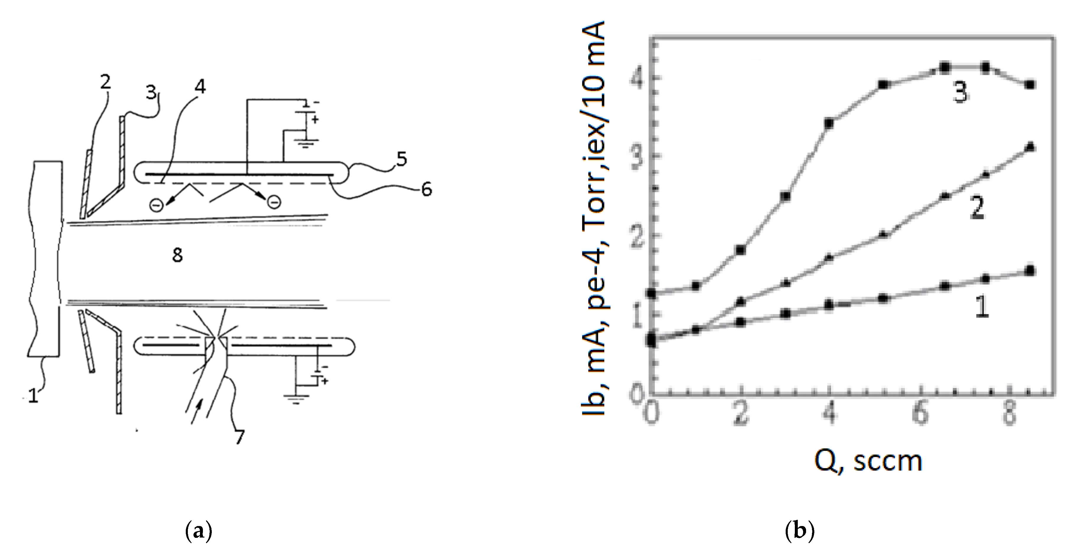
A typical beam line for ion beam production, formation, transport, separation, scanning, collimation, and utilization consists of the ion source, extraction system, analyzer magnet with mass resolving system, scanner magnet, collimator magnet, plasma flooding, deceleration, deflection, and end station for the material processing by the ion beam [19]. Very good space charge compensation is necessary in all regions of beam transport. The strong space charge forces defocus the beam directly after the multicomponent, high perveance beam is extracted from the ion source plasma. The intensity of the single-component ion beam after analysis can be considerably less than the multicomponent beam immediately post-extraction, but the space charge compensation of this beam is also important for prevention of the loss of beam intensity and quality. Prevention of loss of the compensating particles from the beam by the electric field of the extractor is accomplished by suppressor electrode 2 biased negative between the ion source 1 and grounded extractor electrode 3 that reflects the compensating particles back into the beam (see Figure 5a). Negative ions can be introduced into the beam at various locations along the beam trajectory. Specifically, in the ion implanter shown in Figure 3, an electronegative gas can be injected via gas conduits 4, after the ion source 2, after the extraction electrode 1 in tunnel 3 and before analyzer magnet 5, after the analyzer magnet 5 and before scanner magnet 6, and after the scanner magnet 6, and before the collimator magnet 7.
Figure 5a shows an embodiment of a gas injection tunnel, which increases the density of electronegative gas near the beam. The tunnel also reduces the injection rate of gas necessary to generate the required density of electrons and negative ions. The gas injection tunnel has three parts: an outer wall 5, a reflection electrode 6, and an inner mesh screen 4. The outer wall 5 is grounded to prevent stray electric fields from interfering with the beam. Electrode 6 is biased negative to reflect negative ions and electrons back into the beam path. Inner mesh screen 4 has a selected degree of transparency, preferably about 90% transparency. Tube 7 carries the electronegative gas to a nozzle for injection into the tunnel where it disperses into the vacuum.
Ion beam compensation by negative ions is most important for low energy beams because the cross section for electron production during gas ionization by low energy heavy ions is very low, close to zero. The effect of electronegative gas admixture to the 3 keV B+ beam is demonstrated by the results shown in Figure 5b. Ions of 10B+, 11B+, F+, BF+, BF2+ with full current up to 120 mA were extracted from the 2 × 90 mm2 slit of the ion source operating with a BF3 gas discharge. The separated 11B+ beam was monitored after the analyzer magnet by a magnetically suppressed collector. Optimized fluxes of electronegative CF4 gas were injected into the tunnel around the beam after the extractor and after the analyzer. The measured 3 keV, 11B+ ion beam current versus electronegative gas flux is shown in Figure 5b.
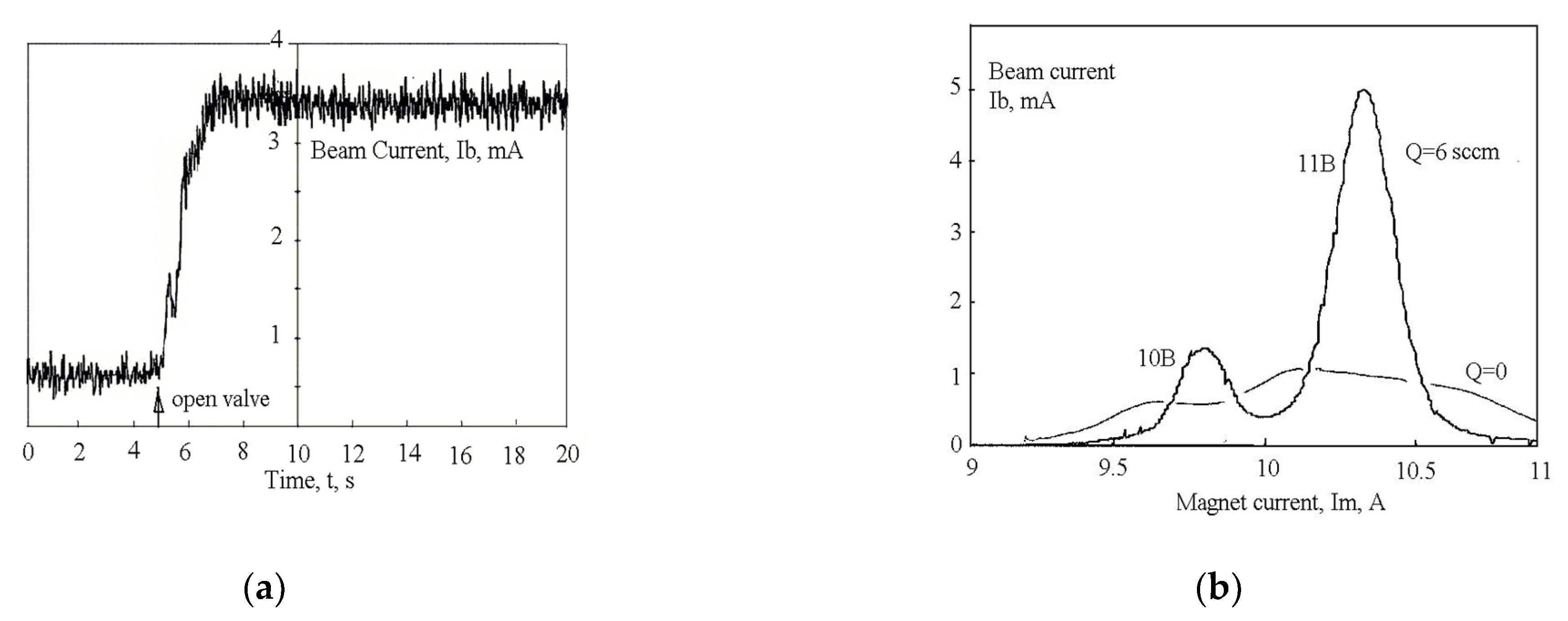
With increase of gas flux, the beam intensity increases from 1.0 mA up to 4.8 mA. With increase of gas density, we see an improvement of focusing by compensation of the repulsive space charge force and the attenuation of the beam by charge exchange loss of ions. For maximum improvement, the electronegative gas should have a high probability of negative ion formation but low cross-section for charge exchange with beam ions. For B+ ions, good results were achieved with CF4, CClF3, and BF3 gases. First experiments with SF6 gas only caused beam attenuation, but further experiments with purified SF6 indicated an increase of intensity. Charge exchange cross sections can be large for low energy beams if the fast and slow particles have similar ionization potentials (quasi resonant charge exchange). The oscillogram reproduced in Figure 6a shows the increase of beam intensity after the analyzer upon injection of electronegative gas. Beams of 11B+ ions with energy 3 keV were transported with injection of BF3 neutralizing gas with flux up to Q = 4.6 sccm (standard cubic centimeters per minute). The improvement in beam quality was approximately the same for all tested electronegative gases.
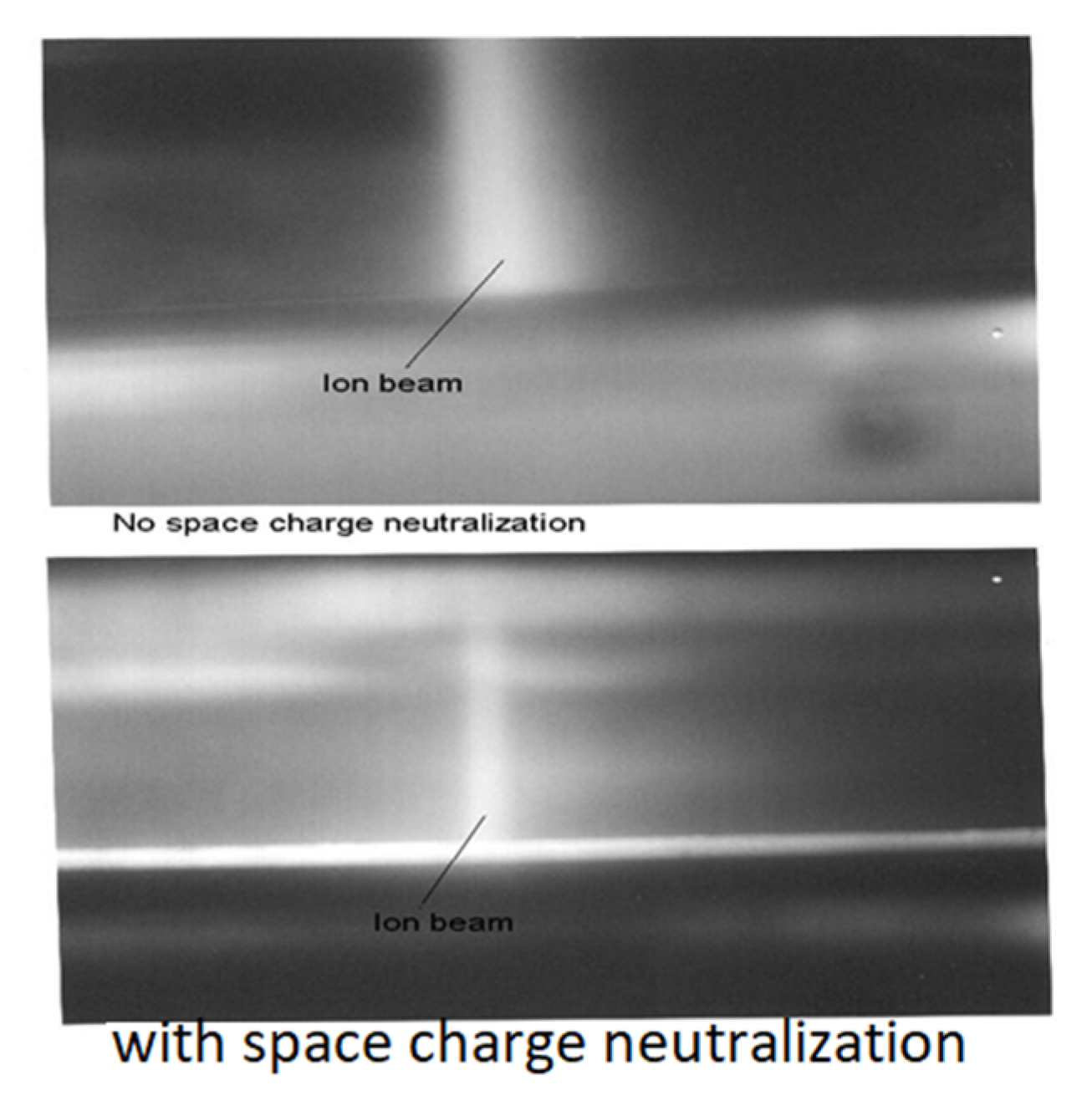
The improvement in a low energy (3 keV) 11B+ beam by injection of electronegative gas is shown in Figure 6b. The beam intensity was increased up to seven times after injection of electronegative gas. The ion beam current density distributions were monitored after magnetic analysis. The ion beam current density is increased significantly and beam transverse size is decreased by optimization of the electronegative gas flux.
Photograph of 11B+ beam after analyzer without electronegative gases and with electronegative gases are shown in Figure 7. With injection of the electronegative gases a transverse beam size is decreased significantly.
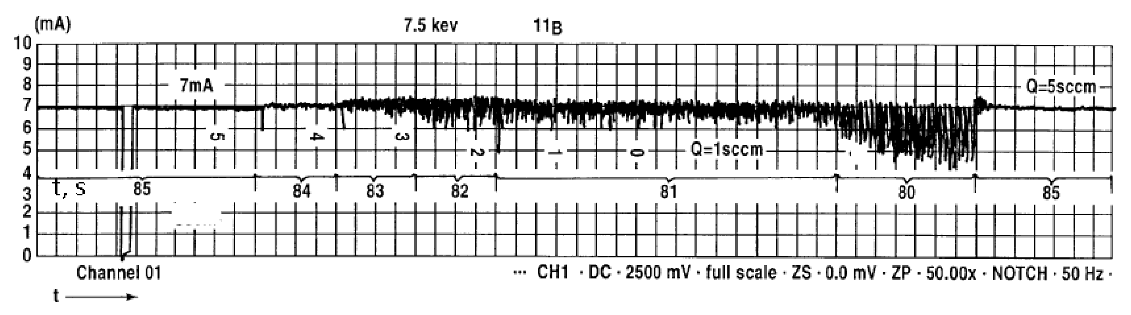
Ion beam instability was damped by admixture of optimized electronegative gas density as shown on Figure 8. The beam current fluctuation level decreased with increased injection of electronegative gases.
4. Conclusions
We have developed and tested a modification to the widely used Bernas-type ion source that has a number of significant advantages. Our “small anode source” incorporates a small, magnetically-insulated anode that is oriented along the magnetic field such that the discharge plasma is driven toward the emission slit (extractor) by the ExB force that is established. The source shows substantially improved ion beam production efficiency, with current of up to 18 mA 11B+ attained after mass analysis of the 15 keV beam, with low levels of beam current oscillations (beam noise). The cathode material was optimized to increase the operating lifetime, which is greater than that of the usual Bernas-type source by a factor of up to five. The wall potential was optimized to suppress material deposition and subsequent flake formation. The transport of low energy beams (e.g., 3 keV as used in the present work) of B+ ions in high current implanters is complicated by the large space charge forces of molecular ions extracted from the discharge in BF3 gas. We have shown that the beam intensity and stability is significantly improved by injecting into the beam a small admixture of electronegative gas, such as BF3, SF6, and CF4, thereby providing space-charge compensation via negative ions rather than by cold electrons.
Author Contributions
Conceptualization, V.D.; formal analysis V.D. and A.D.; investigation, V.D. and A.D.; writing—original draft preparation, V.D.; writing—review and editing, V.D. and A.D.; visualization, V.D.; project administration, V.D.; funding acquisition, V.D.; All authors have read and agreed to the published version of the manuscript.
Funding
Not applicable.
Institutional Review Board Statement
Not applicable.
Informed Consent Statement
Not applicable.
Data Availability Statement
The data that support the findings of this study are available from the corresponding author upon request.
Conflicts of Interest
The authors declare no conflict of interest.
References
- Brown, I.G. (Ed.) The Physics and Technology of Ion Sources; Wiley-VCH: Weinheim, Germany, 2004; p. 133. [Google Scholar]
- E/G Electro-Graph. Available online: https://www.plansee.com/en/about-us/production-sites/usa/eg-electro-graph-usa.html (accessed on 1 June 2006).
- Renau, A.; Smatlak, D. Ion Implantation Technology-96; 96TH182; IEEE Service Center: Piscataway, NJ, USA, 1996; p. 279. [Google Scholar]
- Horsky, T. Indirectly heated cathode arc discharge source for ion implantation of semiconductors. Rev. Sci. Instrum. 1998, 69, 1688. [Google Scholar] [CrossRef]
- Dudnikov, V.; Naser Ghodsi, M. Ion Source. U.S. Patent 618532 B, June 2001. [Google Scholar]
- Dudnikov, V.; Dudnikova, G. Small anode ion source. Rev. Sci. Instrum. 2002, 73, 995–997. [Google Scholar] [CrossRef] [Green Version]
- Pbguns. Available online: www.far-tech.com (accessed on 15 June 2010).
- Low, R.; Jay, T.; Scheuer Alexander, S.; Perel Craig, R.; Chaney, N.; Bassom, J. Flexible Ion Source. U.S. Patent 8330127,01, 11 December 2010. [Google Scholar]
- Vanderberg, B.; Heres, P.; Eisner, E.; Libby, B.; Valinski, J.; Huff, W. Introducing Purion H, a Scanned Spot Beam High Current Ion Implanter. 2019. Available online: https://www.axcelis.com/wp-content/uploads/2019/03/IntroducingThePurionH_Vanderberg_FINAL.pdf (accessed on 1 March 2019).
- Dudnikov, V.; Dudnikov, A. Space charge compensation of low energy ion beam. Rev. Sci. Instrum. 2002, 73, 995. [Google Scholar] [CrossRef] [Green Version]
- Dudnikov, A. Simplified beam line with space charge compensation of low energy ion beam. In Proceedings of the 23th Russian Particle Accelerator Conference (RUPAC2012), Saint-Petersburg, Russia, 24–28 September 2012. [Google Scholar]
- Dudnikov, A. Method of Space Charge Compensation of Positive Ion Beam. Patent RF N 2105368, 13 January 1997. [Google Scholar]
- Dudnikov, V. Space Charge Neutralization of Ion Beam. U.S. Patent 6,329,650, 20 June 1998. [Google Scholar]
- Chen, J.; Victor, M. Benveniste, Method and Apparatus for Ion Beam Neutralization. U.S. Patent 5,703,375, 30 December 1997. [Google Scholar]
- Neslin, M.V. Dynamic of Beam in Plasma; Energoizdat: Moscow, Russia, 1982. (In Russian) [Google Scholar]
- Dudnikov, V. Development and Application of Negative Ion Sources; Springer: Cham, Switzerland, 2019. [Google Scholar]
- Belchenko, Y.; Dudnikov, V. Surface Negative Ion Production in Ion Sources. In Proceedings of the Production and Application of Light Negative Ions, 4th European Workshop, Belfast, Northern Ireland, 28 March 1991; Graham, W., Ed.; pp. 47–66. [Google Scholar]
- Belchenko, Y. Surface negative ion production in ion sources. Rev. Sci. Instrum. 1993, 64, 1385–1393. [Google Scholar] [CrossRef]
- Farley, M.; Dudnikov, V.G.; Nasser-Ghodsi, M. Ion Implantation with Charge Neutralization. U.S. Patent 6,271,529, 7 August 2001. [Google Scholar]
Figure 1.
(a) Schematic of small anode ion source with power supplies, and (b) isometric view. 1 and 4—cathodes, 2—anode body, 3—emission slit, 5—cathode shields, 6—cathode insulators, 7—small anode, 8—small anode insulators, 9—small anode shields, 10 and 11—cathode power supplies, 12—gas discharge power supply, 13—small anode bias power supply.


Figure 2.
(a) Schematic of the extraction system of our small anode low energy ion source, 1—plasma electrode, 2—suppressor electrode, 3—ground electrode, 4—ion beam. (b) Dependence of analyzed 11B+ beam current on discharge current at different beam energies.
Figure 2.
(a) Schematic of the extraction system of our small anode low energy ion source, 1—plasma electrode, 2—suppressor electrode, 3—ground electrode, 4—ion beam. (b) Dependence of analyzed 11B+ beam current on discharge current at different beam energies.

Figure 3.
Schematic of experimental implanter for testing the small anode ion source. 1—extractor, 2—ion source, 3—tunnel, 4—gas injection, 5—analyzer magnet, 6—scanning magnet, 7—collimator magnet, 8—wafer holder.
Figure 3.
Schematic of experimental implanter for testing the small anode ion source. 1—extractor, 2—ion source, 3—tunnel, 4—gas injection, 5—analyzer magnet, 6—scanning magnet, 7—collimator magnet, 8—wafer holder.

Figure 4.
(a) Separated 11B+ ion beam current Ib vs. arc current Id for (2) SAS, and (1) Bernas ion source. (b) Oscillogram showing the degree of beam noise; note the current scale.
Figure 4.
(a) Separated 11B+ ion beam current Ib vs. arc current Id for (2) SAS, and (1) Bernas ion source. (b) Oscillogram showing the degree of beam noise; note the current scale.

Figure 5.
(a) Embodiment of a gas injection tunnel, which increases the density of electronegative gas near the beam and reflects electrons and negative ions into the beam. 1—ion source, 2—suppressor electrode, 3—grounded electrode, 4—inner mesh, 5—outer screen, 6—reflecting electrode, 7—gas delivery system, 8—ion beam. (b) Dependencies of (1) pressure of injected CF3 gas flow, (2) extracted ion current, and (3) analyzed ion beam current, on electronegative gas flow Q.

Figure 6.
(a) Oscillogram showing the increase of beam intensity after the analyzer following injection of electronegative gas; the beam was of 11B+ ions with energy 3 keV and BF3 neutralizing gas with flux up to 4.6 sccm was injected. (b) Mass spectrum of 3 keV B+ beam after analyzer magnet for different neutralizing electronegative gas fluxes.

Figure 7.
Photograph of 11B+ beam after analyzer without electronegative gases and with electronegative gases.
Figure 7.
Photograph of 11B+ beam after analyzer without electronegative gases and with electronegative gases.

Figure 8.
Ion beam current after analyzer showing damping of beam instability by injection of different quantities of electronegative gas. Q is in sccm (standard cubic centimeters per minute).
Figure 8.
Ion beam current after analyzer showing damping of beam instability by injection of different quantities of electronegative gas. Q is in sccm (standard cubic centimeters per minute).

Publisher’s Note: MDPI stays neutral with regard to jurisdictional claims in published maps and institutional affiliations. |
© 2021 by the authors. Licensee MDPI, Basel, Switzerland. This article is an open access article distributed under the terms and conditions of the Creative Commons Attribution (CC BY) license (http://creativecommons.org/licenses/by/4.0/).
Share and Cite
MDPI and ACS Style
Dudnikov, V.; Dudnikov, A. Highly Efficient Small Anode Ion Source. Plasma 2021, 4, 214-221. https://0-doi-org.brum.beds.ac.uk/10.3390/plasma4020013
AMA Style
Dudnikov V, Dudnikov A. Highly Efficient Small Anode Ion Source. Plasma. 2021; 4(2):214-221. https://0-doi-org.brum.beds.ac.uk/10.3390/plasma4020013
Chicago/Turabian StyleDudnikov, Vadim, and Andrei Dudnikov. 2021. "Highly Efficient Small Anode Ion Source" Plasma 4, no. 2: 214-221. https://0-doi-org.brum.beds.ac.uk/10.3390/plasma4020013