
RF and Microwave Ion Sources Study at Institute of Modern Physics

1
Institute of Modern Physics, Chinese Academy of Sciences, Lanzhou 730000, China
2
School of Nuclear Science and Technology, University of Chinese Academy of Sciences, Beijing 100049, China
*
Author to whom correspondence should be addressed.
Plasma 2021, 4(2), 332-344; https://0-doi-org.brum.beds.ac.uk/10.3390/plasma4020022
Submission received: 18 May 2021
/
Revised: 1 June 2021
/
Accepted: 3 June 2021
/
Published: 6 June 2021
(This article belongs to the Special Issue Low Temperature Plasmas for Ion Beam Generation)
Abstract
:Intense ion beam production is of high importance for various versatile applications from accelerator injectors to secondary ion mass spectrometry (SIMS). For these purposes, different types of ion beams are needed and, accordingly, the optimum plasma to produce the desired ion beams. RF-type plasma features a simple structure, high plasma density and low plasma temperature, which is essential for negative ion beam production. A very compact RF-type ion source using a planar coil antenna has been developed at IMP for negative molecular oxygen ion beam production. In terms of high-intensity positive ion beam production, 2.45 GHz microwave power-excited plasma has been widely used. At IMP, we developed a 2.45 GHz plasma source with both ridged waveguide and coaxial antenna coupling schemes, tested successfully with intense beam production. Thanks to the plasma built with an external planar coil antenna, high production efficiency has been achieved, i.e., up to 43%. With 2.45 GHz microwave plasma, the ridged waveguide can support a higher power coupling of high efficiency that leads to the production of intense hydrogen beams up to 90 emA, whereas the coaxial antenna is less efficient in power coupling to plasma but can lead to attractive ion source compactness, with a reasonable beam extraction of several emA.
1. Introduction
The use of radio frequency (RF) to generate plasma dates back to the 1940s. RF plasma and ion sources have found many important applications in plasma cleaning, ion beam etching, ion beam doping, micro-machining and semiconductor fabrication. Today, RF-driven ion sources are widely employed to produce a high-intensity ion beam by particle accelerator community, such as DESY, SNS, JPARC, CERN, etc.
The RF plasma and ion source study at IMP is mainly on producing a high-brightness negative ion beam, which can be used as the primary ion in secondary ion mass spectrometry (SIMS) [1]. There is an increasing need for high-performance SIMS for applications in China. In many SIMS laboratories, an O− or beam produced by a hollow-cathode duoplasmatron is used [2]. Beams with impact energies from 1 to 17 keV and currents up to ~3 μA are attainable. The typical minimum spot sizes lie in the ~1–3 μm range, although 0.15 μm has been shown to be possible for a 16 keV O− beam within the nano-SIMS-based instruments [3]. This type of oxygen ion source has been in use for several decades, but it nevertheless has several disadvantages. Firstly, the spot size is primarily limited by chromatic aberrations introduced as a result of the 5–15 eV energy spread of the ions. This results in a lower beam brightness and lower spatial resolution, and the typical brightness values for oxygen beams from a duoplasmatron source are of the order of 100 A m−2 sr−1 V−1. Therefore, it will potentially limit certain isotopic analyses, requiring positive secondary ions. Secondly, the extracted ion beam intensity depends on many ion source parameters, such as gas flux, magnetic field confined plasma, and the position of the intermediate electrode and cathode. Ion beam current can vary significantly with time, depending on the optimization of the duoplasmatron parameters. Moreover, the cathode is subjected to corrosion caused by magnetically confined oxygen plasma, and the destructive nature of such plasmas requires that these sources will be cleaned or replaced on a routine basis. Thirdly, the lifetime, between 50 and 500 h, is also unpredictable. In order to produce a high-brightness, high spatial resolution primary ion beam for SIMS, the RF-driven ion source study was started at IMP in 2018.
For those accelerators and ion beam application devices that require high-current mono-charge state ion beams, the 2.45 GHz microwave ion source has a wide range of applications, due to its advantages of a long lifespan, a high beam current and good beam quality. The 2.45 GHz microwave ion source was firstly studied and constructed by Sakudo et.al. [4,5] in the 1970s for ion beam implantation, which could extract nearly 15 mA P+ ions by using a slit extraction electrode system. Driven by the development of a linear accelerator and the increasing need for beam current, the 2.45 GHz microwave ion source was thoroughly studied and rapidly developed for various applications since the 1990s [6,7,8,9,10].
The study of the 2.45 GHz microwave ion source at IMP began in the 1990s, and the team had developed a series of microwave ion sources for different purposes, which include the high-current ion sources for high-intensity accelerators and the mini-type ion sources for special experimental platforms. The primary difference between those two types of ion sources is the approach of coupling the microwave power to the ion source’s plasma. In order to produce an intense ion beam, a three-section ridged waveguide coupler is applied to the ion sources using high 2.45 GHz microwave power heating, while the coaxial antenna microwave coupling structure is used for those ion sources that are of a very compact size.
2. RF Plasma and Ion Source
2.1. RF Plasma Generation
The most important advantage of RF-produced plasma is that it can operate with any kind of gas, especially corrosive oxygen gas, which seriously reduces the lifetime of the duoplasmatron when it is used to produce a negative oxygen ion beam. Typically, the discharge chamber is at a pressure of 10−3−10−2 mbar, and a few hundred watts of RF power is needed to excite and maintain a stable plasma. For DC input power (less than several kW), 13.56 MHz is widely used and commercially available. For a high-intensity ion source, such as a spallation neutron source (SNS) negative hydrogen ion source, the RF frequency is generally 2 MHz and the input power can reach up to 100 kW (pulsed mode) [11].
RF discharge plasma can be excited in two ways: (1) capacitively coupled discharge, and (2) inductively coupled discharge. Capacitively coupled plasma (CCP) is excited by a discharge between two electrodes applied with RF power, which generates alternating potential across the electrodes. The CCP method is used to clean contaminated superconducting radio frequency (SRF) cavities [12] and ion source plasma chambers at IMP, and this research work is ongoing. Most RF plasma and ion sources are based on the inductively coupled method, which is also known as inductively coupled plasma (ICP). ICP is generated by an induction coil. Electrons in the gas are heated by an azimuthal electric field generated by the alternating magnetic field around the induction coil, and then acquire enough energy to form plasma.
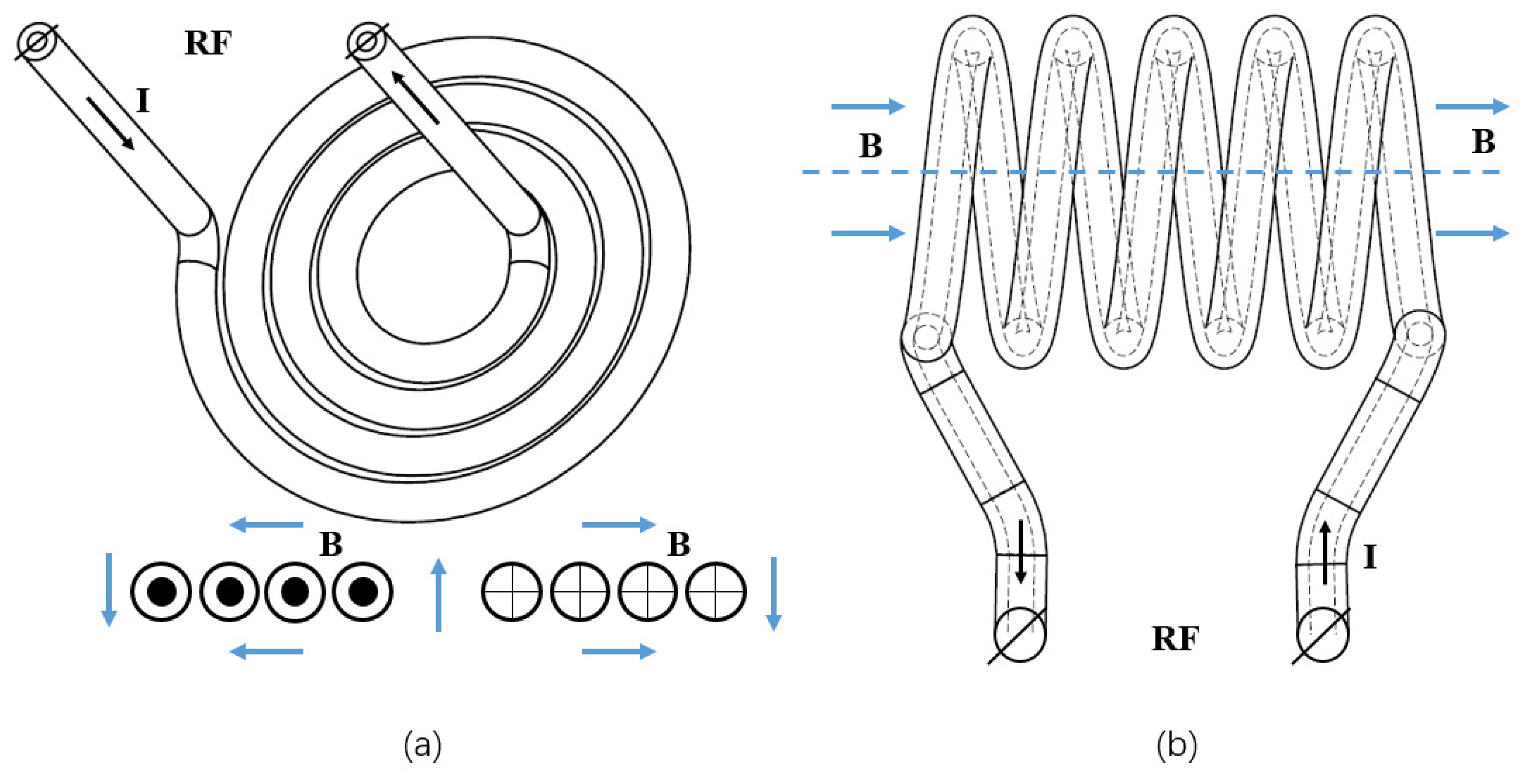
In order to excite and maintain a dense stable inductively coupled plasma, an RF antenna is needed. Generally, the RF antenna can be placed either inside or outside the discharge chamber, which is usually named the internal or external RF antenna in the ion source community. For a high-intensity high duty cycle negative hydrogen ion source, a multicusp magnet with an internal RF coil is widely used [13,14], and a copper-tube RF coil must be coated with porcelain material. When the ion source works with a high duty factor or in continuous wave (CW) operation mode, the lifetime of RF antenna will be affected, and high voltage breakdown may occur with high-input RF power. The application of an external antenna is more extensively used for plasma and ion source studies. Typical antenna coils, which are mostly cylindrical or planar, are shown in Figure 1. Kalvas et al. [15] developed a planar RF coil-driven ion source, and a milliampere H− ion beam was extracted. The ion source design is a multicusp chamber with an external planar spiral RF antenna, behind a flat AlN RF window on the back of the ion source. The maintenance interval reached one month, which was much longer than the filament-driven arc discharge ion source. Jiang et al. [16] developed a mini RF-driven ion source with 1.2 cm and 1.5 cm inner chamber diameters at Lawrence Berkeley National Laboratory. Different helical coupler antennas were tested, and high-brightness positive Ar+, Kr+, H+ ions were extracted. The mini RF-driven ion sources are capable of producing nano-focused ion beams for focused ion beam (FIB) systems.
2.2. Fundamental Processes of Negative Oxygen Ion Formation
For electron collision-produced ions, the fundamental processes and effective cross-section are very important for discharge mode and ion source design [17]. Vibrationally excited oxygen molecules are formed by:
O2 + e → O2(ν = 0→ 1, 2, 3, 4) + e
This process has a peak effective cross-section of about 10−17 cm2 when the electron energy is 10 eV. In 1993, Shyn and Sweeney [18] reported their measurement of the individual vibrational cross-sections for ν = 0→ 1,2,3,4. They obtained the corresponding differential cross-section at the scattering angles of 12–168° for the electron energies of 5–15 eV. Vibrationally excited oxygen molecules usually play an important role in negative ion formation.
Negative oxygen ions may be formed by the dissociative attachment of low-energy electrons to oxygen molecules [19], i.e.,:
O2 + e → O + O−
This process has a mean effective cross-section of about 3 × 10⁻¹⁹ cm2 when the electron energy lies between 4 and 10 eV. For collision energy above 17 eV, O− can be produced through the process of ion-pair formation:
O2 + e → O+ + O− + e
Rapp and Briglia [20] measured O− over the energy range of 4–55 eV. They found the yield of O− increases above 17 eV, and it is suggested that the increase is due to the process (3). According to the measurements, the cross-section for Reaction (3) is almost constant above 25 eV and has a value of 3.5 × 10⁻¹⁹ cm2, which is the same order of magnitude as that for process (2).
The process of formation has been experimentally studied using an electron beam, or swarm technique. From these experimental studies, together with theoretical ones, the attachment process for thermal electrons is understood to proceed in the following way:
First, the electron of ~80 meV is resonantly captured by O2, and unstable is formed. In oxygen gas, the de-excitation of unstable can occur by collision with a third O2 molecule. This process results in a stable negative ion of the oxygen molecule. The three-body rate constant for the above process has been measured by many people, and the typical value is (2.26 ± 0.10) × 10−30 cm6/s at 298 K.
ions may also be formed in charge transfer collisions with atomic negative ions [21], i.e.,:
Reaction (5) is endothermic, with an atomic negative ion energy threshold of several eV. Charge transfer will depend on the energy of the ions involved in the process, and on the particular discharge conditions.
2.3. RF Ion Source Design with an External Antenna
Initially, we tried a filament-driven ion source to extract negative oxygen ion beams, with oxygen and carbon dioxide gases injected [22]. However, after the preliminary operation, we found that the corrosive nature of such plasmas would cause hot-cathode failure. When oxygen gas was injected, the filament could only work for a period from several minutes to several hours before fracture occurred. After the failure of the filament scheme, the RF-powered scheme was studied with the ion source structure and extraction electrodes unchanged, while the backplate was replaced by an aluminum nitride (AlN) window (3 mm thickness) for RF power injection. The goal of the RF negative oxygen ion source was to develop a new type of ion source to produce at least 10 μA of CW O− beam at the SIMS primary ion energy of 10 keV, with a better lifetime and beam stability than those of the duoplasmatron ion source.
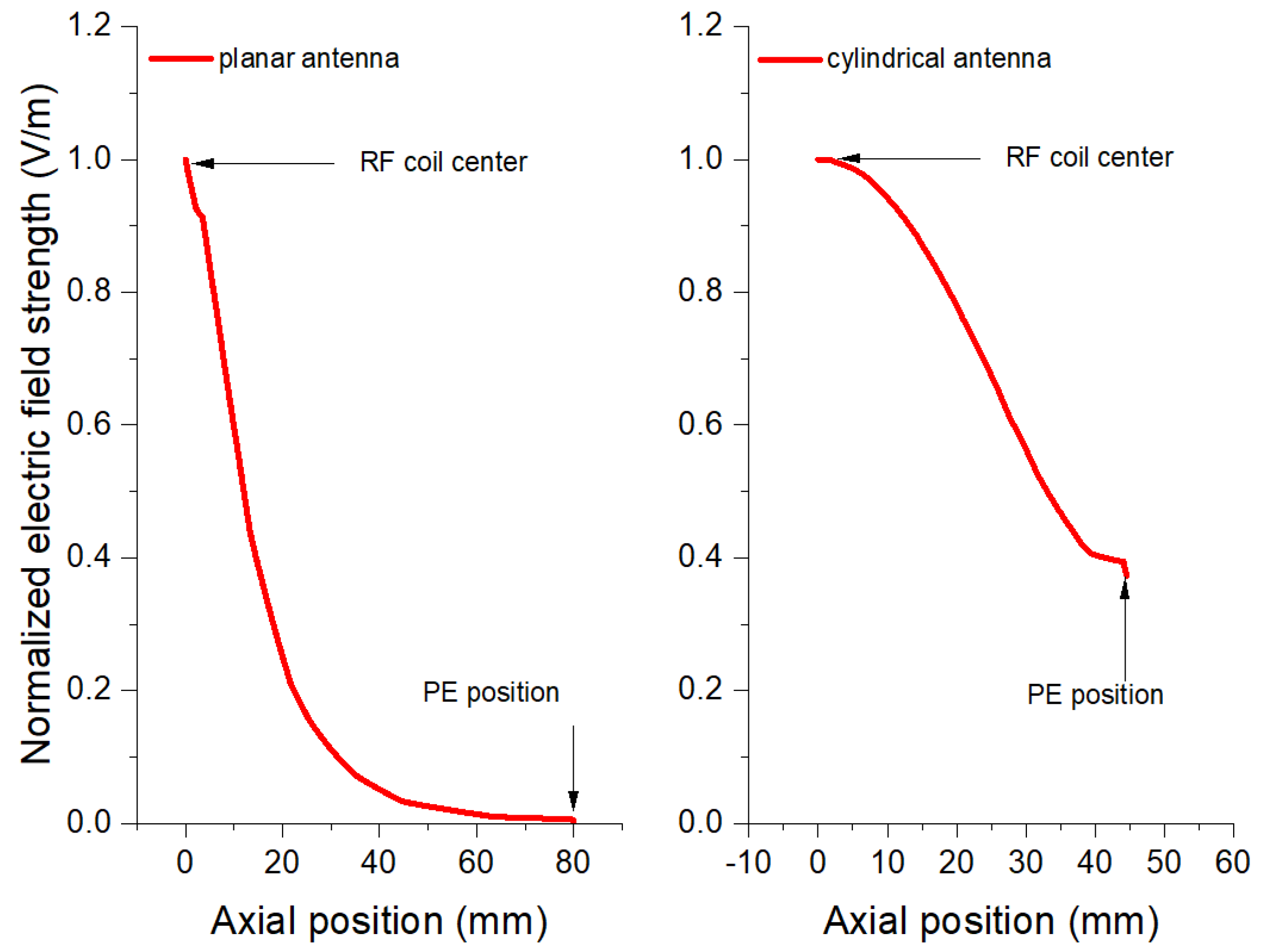
The use of RF ion sources for SIMS applications dates back to the 1960s, at the beginning of SIMS. During those years, different designs were tested. However, one of the major drawbacks of RF-produced plasma was the large energy dispersion (above tens of eV), which caused chromatic aberration and therefore limited the formation of a high-brightness high spatial resolution ion beam for micro-nano-scale applications [23,24]. Ero [25] and Levitskii [26] independently argued that the observed large energy spread anomalies are due to the modification and variation of the plasma potential by energetic electrons that have come under the influence of strong RF electric fields existing in the region between the plasma and the electrode, or between the plasma and the walls. The simulation results of the RF electric field along the central axis with different antenna structures (given in Figure 1) are shown in Figure 2. It can be seen that the RF electric field at plasma electrode (PE) position is near to zero with the planar antenna, while the cylindrical one is around 40% of the field at the RF coil center. Based on the above reasons, the planar antenna is chosen for RF power injection.
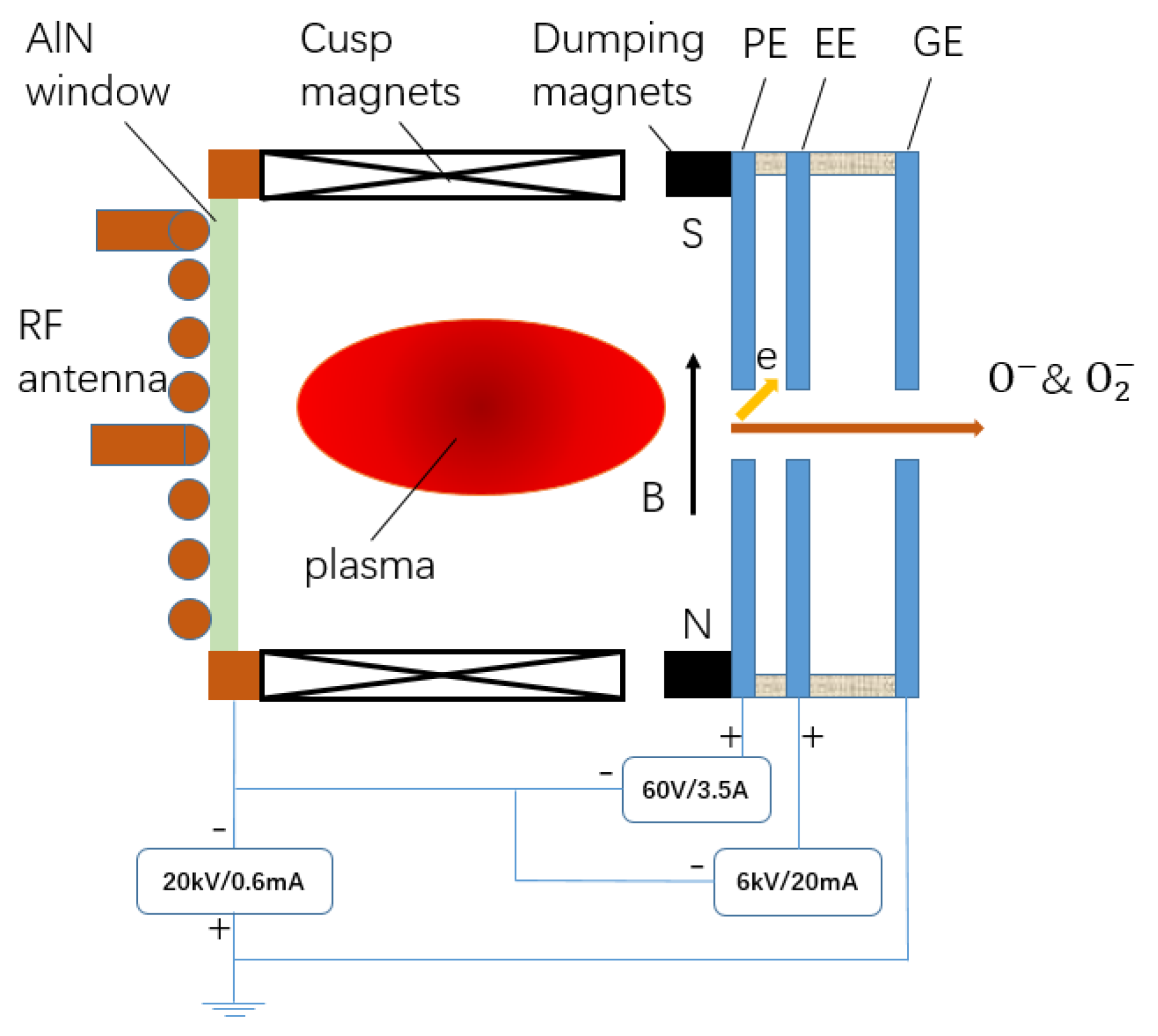
The RF ion source design with an external planar antenna is shown in Figure 3. A three-and-a-half-turns planar copper coil antenna is used to couple the 13.56 MHz RF power into the plasma chamber. The antenna is made of 3 mm diameter copper tubing for water cooling. RF window is aluminum nitride ceramic, which is placed together with the antenna for cooling. The discharge chamber of the RF ion source is made of aluminum, with an inner diameter of 70 mm and 80 mm in length. Multi-cusp magnets are fixed around the discharge chamber to confine the plasma. For different processes of negative oxygen ion formation, the incident electron energies are almost of the same range, so a virtual filter magnetic design is not needed here. Before the plasma electrode (PE), a pair of permanent magnets with a central magnetic field of 160 G were placed to separate co-extracted electrons from negative ions. A three-electrode system is adopted to extract negative ions because this will significantly reduce extraction power. In our case, the ratio of electrons and negative ions may reach 100. For this reason, the electrons must be dumped before the extraction electrode (EE), as shown in Figure 3. After the ground electrode (GE), negative ions will be accelerated to 10–20 keV range which is the requirement for the SIMS primary beam. The apertures of PE, EE, and GE are 2 mm, 3.5 mm, and 5 mm, respectively.
Typical primary ion energy used on SIMS instruments is 5–20 keV, and the negative oxygen ion test setup is designed to operate the source high-voltage terminal at a potential of up to −20 kV. A biased power supply connects the PE with the discharge chamber to optimize negative ion extraction. A 6 kV × 20 mA extraction power supply is used to extract negatively charged particles between PE and EE. A 20 kV × 600 μA high-voltage power supply accelerates ions between the discharge chamber and GE to the required energy level.
2.4. RF Plasma Study and Ion Beam Extraction
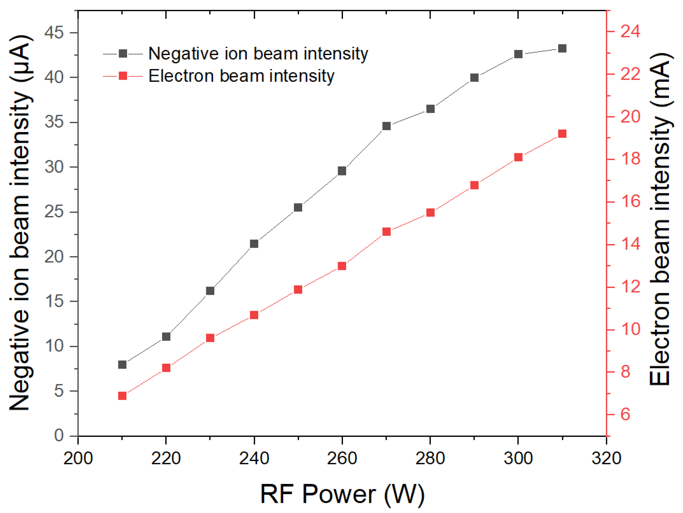
Figure 4 shows the total extracted negative oxygen beam intensity with increasing RF power. During the experiment, some parameters remained unchanged: bias voltage 26 V, ion energy 10 keV, and beam line vacuum 7.3 × 10⁻⁵ mbar. The extraction voltage was optimized to 1.68 kV. The negative ion beam intensity was measured using a Faraday cup (FC), which is placed 800 mm after GE, and the ions drift freely without focusing components. When RF power is 310 W, the maximum beam intensity reaches 43.3 μA, and electron beam intensity, which can be estimated from extraction power supply load, is close to 19.5 mA. It can be seen that electron beam intensity is two orders of magnitude higher than negative ion beam intensity. This is the main reason why a three-electrode extraction system is needed. The maximum RF power is 310 W during this experiment because the total extracted beam intensity (including electrons and negative ions) reaches the maximum load of the extraction power supply.
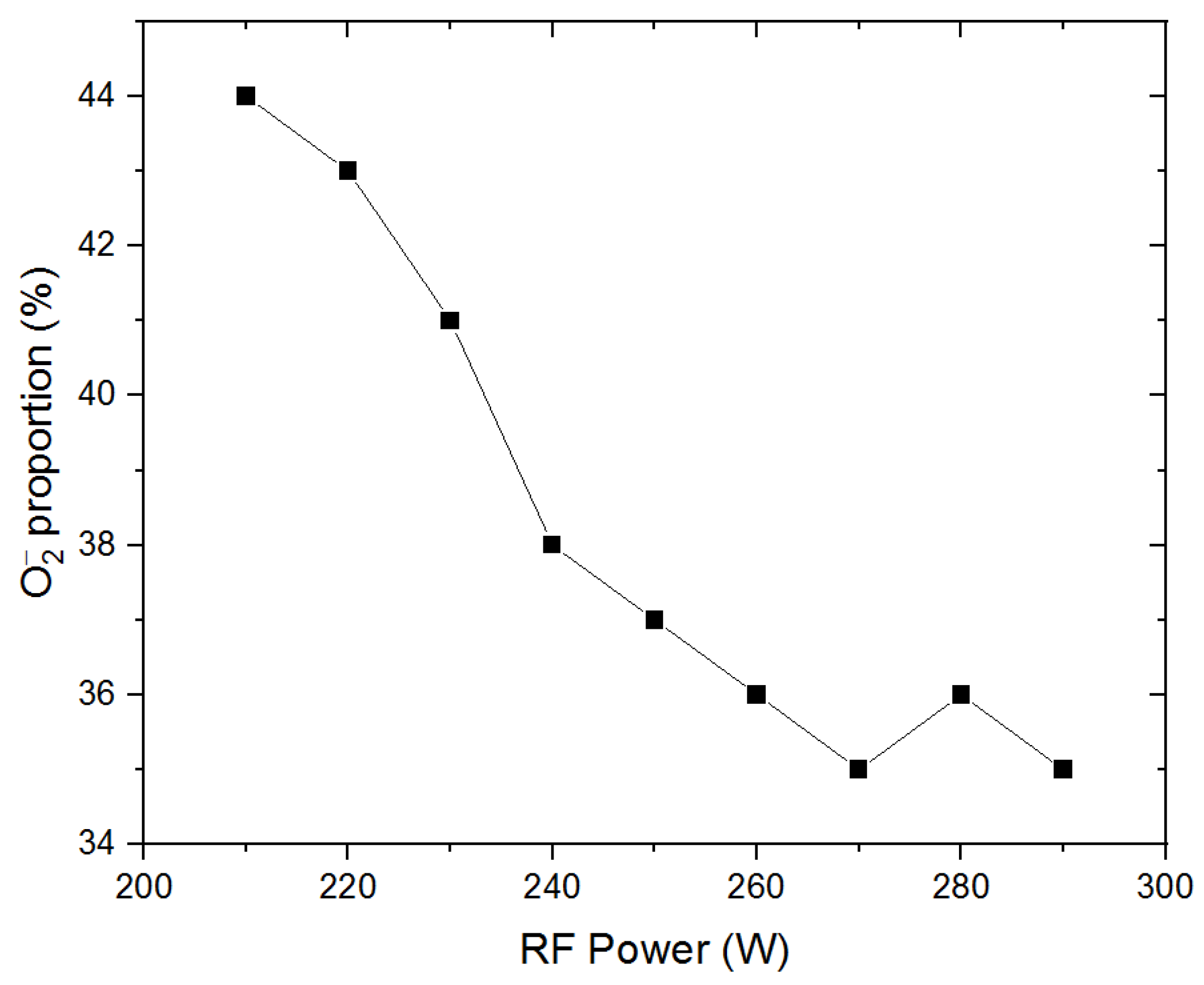
In RF oxygen plasma, and O− are the most abundant negative ions. We analyzed the beam spectrum with a Wien filter placed just before the FC, and the results are shown in Figure 5. Some unchanged parameters in this experiment are ion energy at 10 keV to meet the requirement of SIMS, PE bias voltage 26 V, extraction voltage 1.68 kV and the beam line vacuum, 7.0 × 10⁻⁵ mbar. With the increase of RF power, the proportion of in the total extracted beam decreases from 44% to 35%. This result can be explained by the fundamental processes of negative oxygen ion formation. When RF power increases, electrons in the plasma are heated by the RF field to higher energy, and the probability of Reaction (3) will increase, which results in a greater yield of O− ions. At the same time, Reactions (4) and (5) will be suppressed.
2.5. Summary and Future Plan
A new 13.56 MHz RF-driven planar antenna ion source was tested at IMP. A more than 40 μA negative oxygen ion beam was detected at the beam line terminal when the PE aperture was 2 mm, RF power was about 300 W and the ion energy was 10 keV. In RF-produced plasma, the proportion of reached 44%; this is an encouraging result for SIMS applications. In the near future, further studies will be carried out, including micro-nano ion beam optics and energy spread measurement. In order to get a high-brightness high spatial resolution ion beam, the energy spread must be as small as possible. A planar antenna may solve the problem mentioned above, but more studies are needed. An energy spread analyzer has been developed at IMP for this purpose, and the measurement results will be published soon.
3. Microwave Plasma and Sources
In 1991 Taylor et al. [27] proposed a design for an intense-beam 2.45 GHz microwave ion source for a CW radio frequency quadrupole (RFQ) injector. The proton fraction of the source was up to 90%, and the beam current density was up to 350 mA/cm2, which has been the basis for most of the existing high-intensity 2.45 GHz microwave sources, due to their simplicity and reliability [9,28,29]. The main features include using an impedance matching section to reduce the microwave power reflection between the waveguide and plasma chamber, which could enhance the microwave power coupling efficiency, and using solenoids to generate the desired magnetic field distribution.
3.1. The 2.45 GHz Microwave Ion Source for Intense Beam Applications
For the production of an intense ion beam, the multi-section double-ridged waveguide is generally used as the microwave coupler due to its advantages of high microwave power capacity and smooth impedance transformation between the waveguide and plasma chamber; in our design, a three-section ridged waveguide was used and a 2 mm-thickness aluminum nitride ceramics window was located between the plasma chamber and ridged waveguide to seal the vacuum; the diameter and length of the aluminum plasma chamber is 50 mm and 70 mm, respectively. The required magnetic field is generated by several NdFeB permanent magnet rings with radial or axial magnetization directions, respectively. A pure iron yoke is used as the outer shell of the source body to enhance the axial magnetic field and screen the magnetic field in the extraction area, which could avoid the Penning discharge between the plasma electrode and suppressor electrode. A triode extraction system is used to extract the ion beam, and reduce the extraction beam emittance. The typical aperture of the plasma electrode is Ø6.5 mm. The configuration of the ion source is shown in Figure 6.
The electromagnetic simulation of the designed double-ridged waveguide coupler is shown in Figure 7. In the simulation, the impedance of the plasma chamber was assumed to be 50 Ω. The design of the coupler followed the principles of 1/4 wavelength impedance matching theory, and the length of each ridged waveguide section is equal to 1/4 guided wavelength of 2.45 GHz microwave to match the impedance of adjacent loads. The ridged waveguide coupler and microwave transition waveguide are connected by a WR-340 to WR-284 transitional waveguide.
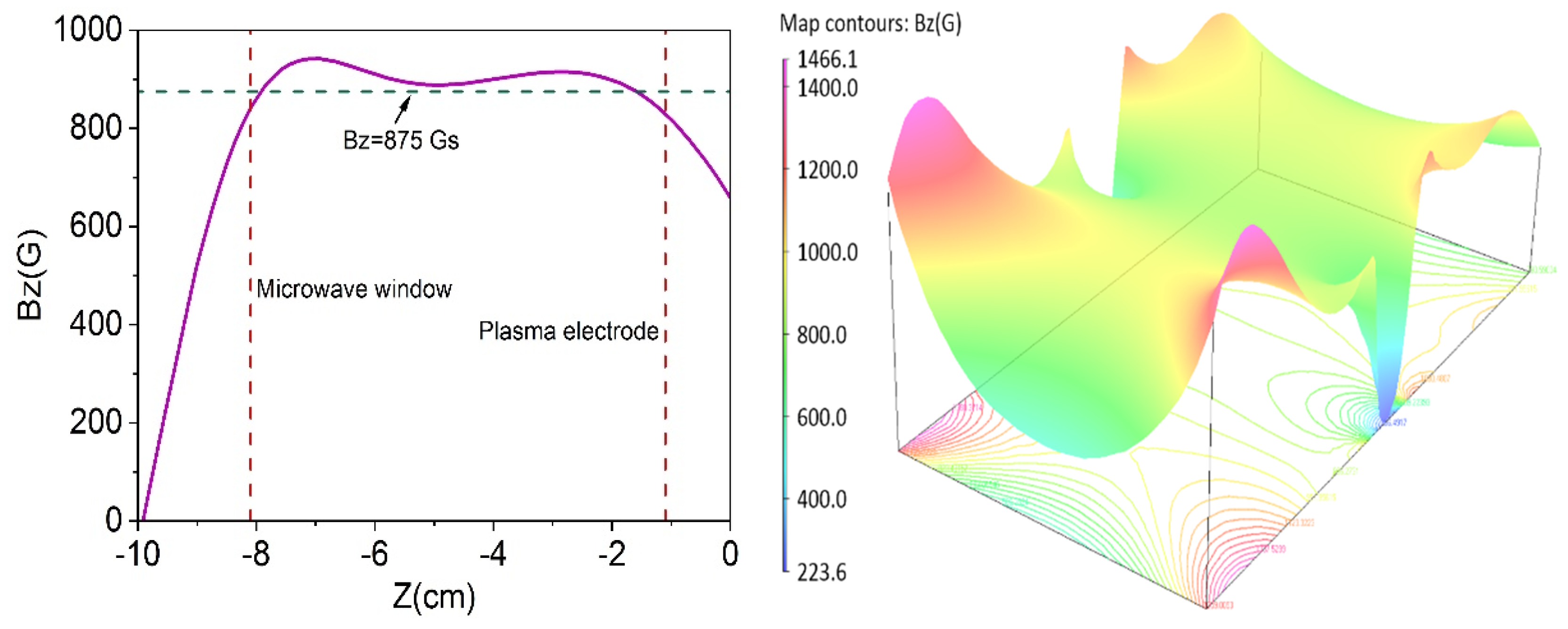
The magnetic field distribution is crucial for the generation of stable and high-density plasma in microwave ion sources. In order to form over-dense plasma in a uniform magnetic field, according to Sakudo’s study, the plasma density could be improved with the condition of BECR < B < 1.3 BECR (BECR = 875 G for 2.45 GHz microwave) [30], which would permit the propagation of right-hand polarized waves in those off-resonance regions. The calculated magnetic field distribution of our intense ion beam source is shown in Figure 8. The maximum magnetic field strength along the axial direction (Bz) is 950 G, and the ECR zone is near the microwave window; besides, as mentioned before, the stray field in the extraction electrodes region was screened to avoid the Penning discharge.
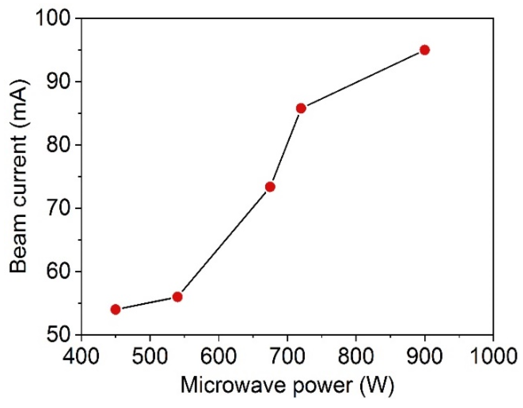
The maximum extraction beam current under differing input microwave power is shown in Figure 9, when hydrogen was used as the working gas, the extraction voltage is 50 kV and the aperture of the plasma electrode is Ø6.5 mm. The maximum total extraction beam current is about 95 mA, and the corresponding microwave power is 900 W.
The high-intensity 2.45 GHz microwave ion source developed at IMP has been used for several high-power accelerators. A 2.45 GHz microwave ion source with a total extraction beam current over 80 mA was developed for the compact pulsed hadron source (CPHS) at Tsinghua University [31], which required a pulsed proton beam of 60 mA, and the developed ion source had previously shown high reliability and stability during its almost 10 years of operation since 2012. Another application of a high-intensity 2.45 GHz microwave ion source at IMP is the China initiative accelerator-driven system (CiADS) project, which requires a CW proton beam of 10 mA [32], where high availability, reliability and stability are the key issues. As of 2018, the ion source system had enabled >4000 h of beam commissioning time for the ADS linac.
3.2. The Coaxial Antenna Type Microwave Ion Source
Generally, the intense beam microwave ion sources use the WR-320 or WR-284 waveguide components as the microwave transition system, which usually includes the circulator, three-stab tuner, impedance matching section, and others. Consequently, the microwave system of the ion source is sophisticated and bulky. For the ion beam application devices with strict restrictions on system compactness, while requiring a relatively weak beam current, a 2.45 GHz microwave ion source based on the coaxial antenna coupling structure has obvious advantages, due to its extremely compact structure. In 1984, Ishikawa et al. [33] developed a compact coaxial antenna-type microwave ion source that could extract a several milli-amperes Ar+ ion beam through a 2 mm aperture plasma electrode, and this kind of microwave ion source was also studied and developed at IMP.
To eliminate the microwave power reflection, the coaxial antenna structure should match the impedance between the plasma chamber and coaxial transition cable. The impedance Z of the coaxial antenna for the TEM mode is determined by the diameter ratio of the inner conductor and outer conductor as the following equation:
where εr is the relative permittivity, ro is the radius of the outer conductor, and ri is the radius of the inner conductor. In our design, both the impedance of the plasma chamber and the coaxial cable were assumed to be 50 Ω.
The microwave electric field distribution and deposited RF power in the designed coaxial antenna-type ion source were calculated via an RF-plasma coupled simulation with COMSOL multiphysics code [34]. The working gas is hydrogen in the simulation, and the main reaction processes taken into account are listed in Table 1 [35].
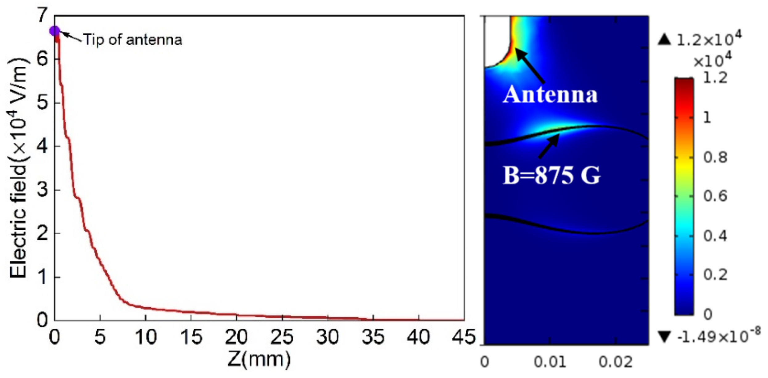
The simulated microwave power deposition and normal electric field strength along the axial direction are shown in Figure 10, with an input microwave power of 100 W and 1 Pa hydrogen gas pressure in the simulation; the radius of the simulation model is 25 mm.
The simulation results show that the normal electric field strength is attenuated exponentially along the axial direction, and most of the microwave power is absorbed around the antenna and the ECR surface (B = 875 G) near the antenna tip.
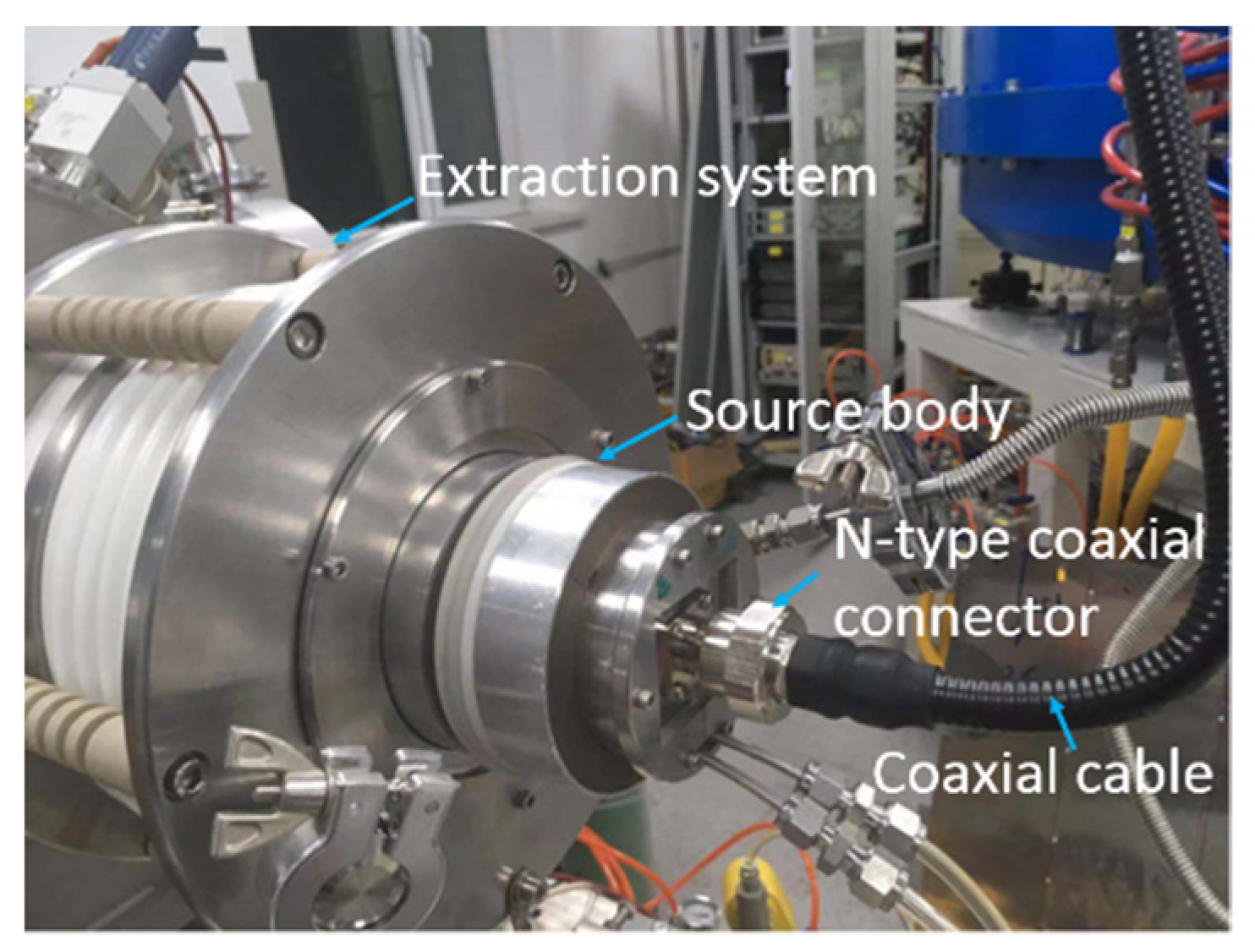
According to the simulation results, a coaxial antenna microwave ion source was developed. A coaxial antenna is used as the microwave coupler and two NdFeB permanent magnet rings are used to generate the magnetic field. The diameter and length of the discharge chamber are both 50 mm. Figure 11 shows the configuration of the designed ion source.
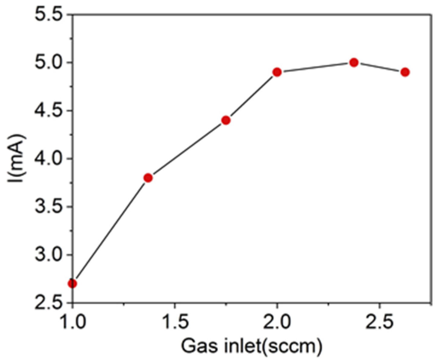
The maximum total extraction beam current is 5.0 mA when the working gas is hydrogen, the corresponding plasma electrode aperture and extraction voltage is 5 mm and 35 kV respectively, and the input microwave power is 150 W. The extraction beam currents under different hydrogen gas consumption rates are shown in Figure 12.
The maximum extraction beam current of the antenna-type microwave ion source is much lower when compared with the ion sources that used a ridged waveguide coupler under the same operating conditions; the main reason for this is the inefficiency of the coaxial antenna structure for microwave-plasma coupling, and consequently, the antenna-type microwave ion source at IMP was developed for the application with the requirements of compactness and low beam intensity.
4. Summary
Based on the plasma characteristics, we have developed both RF- and microwave-type plasma technologies to produce intense ion beams. O− and production is of high importance for SIMS application, whereas the existing technologies, including the duoplasmatron source and the filament-driven arc discharge ion source, are not a promising solution with regard to ion beam intensity, lifespan and brightness. We have developed a negative oxygen ion beam source using an external planar coil antenna RF coupling plasma technology, which is implemented to the existing filament-driven arc discharge ion source. The test results indicate that this type of plasma can provide a very suitable condition for a high yield of O− and , and especially of where the ratio is high, up to 43% in the extracted beam.
2.45 GHz microwave heating is another widely utilized method to build dense plasma for intense beam production. We demonstrated that both ridged waveguide and coaxial antenna coupling schemes are feasible for building the plasma. In terms of high beam intensity needs—for instance, the injector ion sources for linac required a 30~100 emA proton beam—the first solution with the ridged waveguide is mandatory, as it will need high power feeding and high-efficiency coupling. The antenna solution will provide promising compactness for versatile applications that might need a small footprint and a low cost. The prototype ion source of the coaxial antenna features a size of Ø100 mm × 100 mm, with typically a 5 mA hydrogen beam extraction.
Author Contributions
Negative ion source development, Q.Y.J.; coaxial antenna source, Y.G.L.; negative ion source commissioning, Y.Z.; ridged waveguide ion source Q.W.; test bench setup, Y.J.Z.; projection design and organizing, L.T.S. All authors have read and agreed to the published version of the manuscript.
Funding
This work is supported by Department of Science and Technology of Shandong province “Deep-sea resource preservation and development platform”, and NSFC (contract No. 12025506).
Data Availability Statement
The data presented in this study are available on request from the corresponding author.
Conflicts of Interest
The authors declare no conflict of interest. The funders had no role in the design of the study; in the collection, analyses, or interpretation of data; in the writing of the manuscript, or in the decision to publish the results.
References
- Van der Heide, P. Secondary Ion Mass Spectrometry: An Introduction to Principles and Practices, 1st ed.; John Wiley & Sons, Inc.: Hoboken, NJ, USA, 2014; pp. 159–167. [Google Scholar]
- Pillatsch, L.; Wirtz, T.; Migeon, H.-N.; Scherrer, H. Use of a duoplasmatron ion source for negative ion generation. Nucl. Instrum. Methods Phys. Res. Sect. B Beam Interactions Mater. Atoms 2011, 269, 1036–1040. [Google Scholar] [CrossRef]
- Malherbe, J.; Penen, F.; Isaure, M.-P.; Frank, J.; Hause, G.; Dobritzsch, D.; Gontier, E.; Horréard, F.; Hillion, F.; Schaumlöffel, D. A new radio frequency plasma oxygen primary ion source on nano secondary ion mass spectrometry for improved lateral resolution and detection of electropositive elements at single cell level. Anal. Chem. 2016, 88, 7130–7136. [Google Scholar] [CrossRef] [PubMed]
- Sakudo, N.; Tokiguchi, K.; Koike, H.; Kanomata, I. Microwave ion source for high-current implanter. Rev. Sci. Instrum. 1978, 49, 940. [Google Scholar] [CrossRef] [PubMed]
- Sakudo, N.; Tokiguchi, K.; Koike, H. Microwave ion source for high current metal beams. Vacuum 1984, 34, 245–249. [Google Scholar] [CrossRef]
- Takeshita, T.; Unagami, T.; Kogure, O. Study of ECR hydrogen plasma treatment on poly-Si thin film transistors. Jpn. J. Appl. Phys. 1988, 27, L2118. [Google Scholar] [CrossRef]
- Tokiguchi, K.; Seki, T.; Amemiya, K.; Yamashita, Y. Advanced microwave ion source for 100 mA-class SIMOX ion implantation. In Proceedings of the 11th IEEE International Conference on Ion Implantation Technology, Austin, TX, USA, 16–21 June 1996; pp. 287–290. [Google Scholar]
- Popov, O.A. Effects of magnetic field and microwave power on electron cyclotron resonance type plasma characteristics. J. Vac. Sci. Technol. A Vac. Surf. Film. 1991, 9, 711–716. [Google Scholar] [CrossRef]
- Gobin, R.; Beauvais, P.Y.; Delferrière, O.; De Menezes, D.; Tuske, O.; Adroit, G.; Gauthier, Y.; Harrault, F. A 140 mA cw deuteron electron cyclotron resonance source for the IFMIF-EVEDA project. Rev. Sci. Instrum. 2008, 79, 02B303. [Google Scholar] [CrossRef] [PubMed]
- Waldmann, O.; Ludewigt, B. A permanent magnet microwave ion source for a compact high yield neutron generator. AIP Conf. Proc. 2011, 1336, 479–482. [Google Scholar]
- Brown, I.G. The Physics and Technology of Ion Sources, 2nd ed.; WILEY-VCH Verlag: Weinheim, Germany, 2004; pp. 163–175. [Google Scholar]
- Wu, A.; Yang, L.; Hu, C.; Li, C.; Huang, S.; Li, Y.; Chu, Q.; Xiong, P.; Guo, H.; Yue, W.; et al. In-situ plasma cleaning to decrease the field emission effect of half-wave superconducting radio frequency cavities. Nucl. Instrum. Methods Phys. Res. A 2018, 905, 61–67. [Google Scholar] [CrossRef]
- Stockli, M.P.; Han, B.; Clemmer, M.; Cousineau, S.M.; Justice, A.; Kang, Y.W.; Murray, S.N.; Pennisi, T.R.; Piller, C.; Stinson, C.M.; et al. Upgrading the LANSCE accelerator with a SNS RF-driven H− ion source. Rev. Sci. Instrum. 2020, 91, 013321. [Google Scholar] [CrossRef]
- Shinto, K.; Ohkoshi, K.; Shibata, T.; Nanmo, K.; Ikegami, K.; Takagi, A.; Namekawa, Y.; Ueno, A.; Oguri, H. Progress of the J-PARC cesiated RF-driven negative hydrogen ion source. AIP Conf. Proc. 2018, 2052, 050002. [Google Scholar]
- Kalvas, T.; Tarvainen, O.; Komppula, J.; Koivisto, H.; Tuunanen, J.; Potkins, D.; Stewart, T.; Dehnel, M.P. A CW radiofrequency ion source for production of negative hydrogen ion beams for cyclotrons. AIP Conf. Proc. 2015, 1655, 030015. [Google Scholar]
- Jiang, X.; Ji, Q.; Chang, A.; Leung, K.N. Mini rf-driven ion sources for focused ion beam systems. Rev. Sci. Instrum. 2003, 74, 2288–2292. [Google Scholar] [CrossRef]
- Stoffels, E.; Stoffels, W.W.; Vender, D.; Kando, M.; Kroesen, G.M.W.; De Hoog, F.J. Negative ions in a radio-frequency oxygen plasma. Phys. Rev E 1995, 51, 2425–2435. [Google Scholar] [CrossRef] [PubMed]
- Shyn, T.W.; Sweeney, C.J. Vibrational-excitation cross sections of molecular oxygen by electron impact. Phys. Rev. A 1993, 48, 1214–1217. [Google Scholar] [CrossRef] [PubMed]
- Whitlock, W.S.; Bounden, J.E. Negative oxygen ions from a glow discharge source. Proc. Phys. Soc. 1961, 77, 845–852. [Google Scholar] [CrossRef]
- Rapp, D.; Briglia, D. Total cross sections for ionization and attachment in gases by electron impact. II. Negative-ion formation. J. Chem. Phys. 1965, 43, 1480–1489. [Google Scholar] [CrossRef]
- Midey, A.; Dotan, I. Kinetics for the reactions of O− and O2− with O2(a1Δg) measured in a selected ion flow tube at 300 K. J. Phys. Chem. A 2007, 111, 5218–5222. [Google Scholar] [CrossRef]
- Jin, Q.Y.; Zhou, Y. Production of O− and O2− beams with the negative ion source at Institute of Modern Physics. Rev. Sci. Instrum. 2019, 90, 113317. [Google Scholar] [CrossRef] [PubMed]
- Blanc, D. Les sources d’ions à excitation électrique de haute fréquence. J. Phys. Radium. 1961, 22, 230–246. [Google Scholar] [CrossRef]
- Slodzian, G. Étude d’une méthode d’analyse locale chimique et isotopique utilisant l’émission ionique secondaire. Ann. Phys. 1964, 13, 591–648. [Google Scholar] [CrossRef]
- Ero, J. Radiofrequency modulation in the Thoneman ion source. Nucl. Instrum. 1958, 3, 303–306. [Google Scholar] [CrossRef]
- Levitskii, S.M. An investigation of the breakdown potential of a high frequency plasma in the frequency and pressure transition regions. Sov. Phys. Tech. Phys. 1958, 2, 887–891. [Google Scholar]
- Taylor, T.; Wills, J.S.C. A high-current low-emittance DC ECR proton source. Nucl. Instrum. Methods Phys. Res. A 1991, 309, 37–42. [Google Scholar] [CrossRef]
- Sherman, J.; Arvin, A.; Hansborough, L.; Hodgkins, D.; Meyer, E.; Schneider, J.D.; Stevens, R.R., Jr.; Thuot, M.; Zaugg, T. Development of a 130-mA, 75-kV high voltage column for high-intensity DCproton injectors. Rev. Sci. Instrum. 1998, 69, 1017–1019. [Google Scholar] [CrossRef] [Green Version]
- Cui, B.; Wang, R.; Ma, Y.; Li, L.; Jiang, C.; Jiang, W. A high intensity microwave ion source for high current RFQ. Rev. Sci. Instrum. 2004, 75, 1457–1459. [Google Scholar] [CrossRef]
- Sakudo, N. Microwave ion sources for industrial applications. Rev. Sci. Instrum. 2000, 71, 1016–1022. [Google Scholar] [CrossRef]
- Wei, J.; Chen, H.; Cheng, C. The compact pulsed hadron source: A design perspective. J. Korean Phys. Soc. 2010, 56, 1928–1936. [Google Scholar] [CrossRef]
- Wu, Q.; Zhang, Z.M.; Sun, L.T.; Yang, Y.; Ma, H.Y.; Cao, Y.; Zhang, X.Z.; Zhao, H.W. A 2.45 GHz intense proton source and low energy beam transport system for China Initiative Accelerator Driven Sub-Critical reactor systema. Rev. Sci. Instrum. 2014, 85, 2. [Google Scholar] [CrossRef] [PubMed]
- Ishikawa, J.; Takeiri, Y.; Takagi, T. Axial magnetic field extraction type microwave ion source with a permanent magnet. Rev. Sci. Instrum. 1984, 55, 449–456. [Google Scholar] [CrossRef]
- COMSOL Website. Available online: https://www.comsol.co.in/products (accessed on 18 May 2021).
- Janev, R.K.; Reiter, D.; Samm, U. Collision Processes in Low-Temperature Hydrogen Plasmas; Forschungszentrum Jülich GmbH: Jülich, Germany, 2003; pp. 8–107. [Google Scholar]
Figure 1.
Two RF antenna patterns used for ICP: (a) planar antenna (b) cylindrical antenna.

Figure 2.
RF electric field distribution along the axial position.

Figure 3.
Schematic diagram of RF negative oxygen ion source.

Figure 4.
Negative ion beam intensity measured by Faraday cup vs. RF power.

Figure 5.
The proportion of in total extracted ion beam vs. RF power.

Figure 6.
Configuration of the designed intense ion beam source.

Figure 7.
Simulated electric field distribution with 1 W input power through a TE10 mode port.

Figure 8.
Calculated Bz along the axial direction and histogram in the midplane of the plasma chamber.
Figure 8.
Calculated Bz along the axial direction and histogram in the midplane of the plasma chamber.

Figure 9.
The extraction beam current under different inputs of microwave power.

Figure 10.
Simulated normal RF electric field strength along the axial direction, and RF power deposition (W/m3).
Figure 10.
Simulated normal RF electric field strength along the axial direction, and RF power deposition (W/m3).

Figure 11.
Picture of coaxial antenna microwave ion source setup.

Figure 12.
Extraction beam current under the different hydrogen gas consumption rates (standard cubic centimeter per minute (sccm)).
Figure 12.
Extraction beam current under the different hydrogen gas consumption rates (standard cubic centimeter per minute (sccm)).


Table 1.
Main reactions considered in the simulation.
| Reaction Type | Reaction |
|---|---|
| Elastic collision | e + H2→e + H2 e + H→e + H |
| Dissociative excitation | e + H2→e+ H + H e + →e+ H + H+ e + →e + 2H + H+ e + H+ →e + H+ |
| Dissociative combination | e+ →H + H e+ →H + H+H |
| Excitation | e + H→e + H* |
| generation | H2 + → + H |
| Ionization | e + H→2e + H+ e + H*→2e+ H+ e + H2→2e+ |
| Reaction with wall | H + wall→1/2H2 + wall→1/2H2 H + wall→1/2H2 + wall→H + H2 |
H* is excited hydrogen atom.
Publisher’s Note: MDPI stays neutral with regard to jurisdictional claims in published maps and institutional affiliations. |
© 2021 by the authors. Licensee MDPI, Basel, Switzerland. This article is an open access article distributed under the terms and conditions of the Creative Commons Attribution (CC BY) license (https://creativecommons.org/licenses/by/4.0/).
Share and Cite
MDPI and ACS Style
Jin, Q.Y.; Liu, Y.G.; Zhou, Y.; Wu, Q.; Zhai, Y.J.; Sun, L.T. RF and Microwave Ion Sources Study at Institute of Modern Physics. Plasma 2021, 4, 332-344. https://0-doi-org.brum.beds.ac.uk/10.3390/plasma4020022
AMA Style
Jin QY, Liu YG, Zhou Y, Wu Q, Zhai YJ, Sun LT. RF and Microwave Ion Sources Study at Institute of Modern Physics. Plasma. 2021; 4(2):332-344. https://0-doi-org.brum.beds.ac.uk/10.3390/plasma4020022
Chicago/Turabian StyleJin, Qian Y., Yu G. Liu, Yang Zhou, Qi Wu, Yao J. Zhai, and Liang T. Sun. 2021. "RF and Microwave Ion Sources Study at Institute of Modern Physics" Plasma 4, no. 2: 332-344. https://0-doi-org.brum.beds.ac.uk/10.3390/plasma4020022