
A Few Points of the Engineering Logic Discussed in ITER EDA on Evaluation of Halo- and AVDE-Induced Loads in Tokamaks

ITER IO, 13067 St. Paul-lez-Durance, France
Plasma 2021, 4(3), 366-374; https://0-doi-org.brum.beds.ac.uk/10.3390/plasma4030025
Submission received: 8 May 2021
/
Revised: 7 June 2021
/
Accepted: 18 June 2021
/
Published: 22 June 2021
(This article belongs to the Special Issue Plasma Disruptions)
Abstract
:All tokamaks are designed to withstand a certain number of energetic electromagnetic (EM) transients caused by uncontrolled terminations of plasma pulses, including symmetric and asymmetric plasma vertical displacement events: VDEs and AVDEs. These events generate significant pulsed EM loads in all conductive components and coils. Axially symmetric transient EM loads induced by VDEs without Halo current have been calculated well since the 1980s; however, Halo-related EM load components and lateral loads associated with AVDEs still cause discussions. The author worked on fast plasma and EM transients in tokamaks quite a while ago then deviated to other areas but has been keeping track of the topic since. He is aware of discussions of the modelling of Halo currents and of significant scatter present in current estimates for AVDE-induced lateral loads and contends that some points of engineering logic formulated earlier on this topic may help reduce these uncertainties. This article summarises a few points of the engineering understanding developed in informal discussions within the ITER EDA team with the purpose to preserve these points for all tokamak developments.
1. Introduction
Back in the 1990s, the mechanical instrumentation of the JET tokamak registered significant net lateral reaction forces in the supports of the vacuum vessel (VV) during some variants of plasma vertical displacement events (VDEs). Such asymmetric loads found an explanation in gradually developing plasma asymmetry: asymmetric VDE, later named AVDE. The so-called Halo current, closing partly through the plasma periphery and partly through the surrounding conductive structures, plays an important role in the last stages of VDE and AVDE. Predictions of Halo-related and AVDE-induced components of EM loads remain a subject of discussion since the ITER Conceptual and Engineering Design Activities (ITER CDA and EDA, [1,2,3]). They are a part of a challenging numerical task: simulation of 3D plasma evolution at AVDE consistent with the distorted pattern of Halo currents and EM transients in VV having their own design asymmetries (different ports, etc.). The author worked on simulation of linked EM and plasma transients in the past [4,5] and now works in other areas but has followed the topic from those times. For this reason, this paper does not offer new quantitative results. Instead, it records a few points of engineering understanding reached in the ITER EDA team, particularly on EM load balance in the presence of Halo current and on the evaluation of AVDE-induced lateral loads. The author believes that such a recollection will help steer more efficiently presently running numerical studies aiming at practical engineering goals. It should be noted that that the engineering logic described here was formulated through friendly discussions with several experts who worked in the ITER CDA and EDA team in the 1990s [1,2,3].
This paper is comprised of five concise sections and concentrates on factors impacting net EM load balance in a presence of the Halo layer and especially lateral loads since calculations of symmetric VDE-induced EM loads with an absent model of the Halo layer were performed well by many teams since the 1980s [1,2].
2. The Engineering Task Is to Find Transient EM Loads at VV and Magnets, Not at the Plasma
Our reader knows well that at all stages of a plasma pulse in typical tokamaks, the plasma as a whole does not move with Alfven speeds and accordingly net EM loads (net force and torque vectors in 3D space) acting at the plasma as a whole remain practically zero during VDE and AVDE. The reader knows also that a typical tokamak represents a practically “closed system” for EM loads. One can say that the plasma (while it exists) serves as an “EM force-free link” between two EM-loaded objects: (1) vacuum vessel with all in-vessel parts and in-vessel coils and (2) the magnets composed of all coils (except in-vessel coils) and relevant structures. This paper compacts these long definitions in shorter terms: “VV” and “magnets.” This balance of net EM loads between VV and the magnets remains valid with either absence or presence of the Halo currents, as detailed below.
Note that in some papers, the original term “Halo current” evolved to different meanings, while in others, replaced by a new term “Giro current.” Here, we use the term “Halo current” in its original definition (in the 1990s)—as a loop of current closed partly through plasma periphery and partly through conductive structures and excited as a result of the conservation of the toroidal magnetic flux in a volume wrapped by this loop.
EM codes operate directly with 3D patterns of fields, current densities, and distributed EM loads, and then can calculate vectors of net EM loads. This paper, for its purposes, mentions mostly net EM loads.
The engineering task should not conclude with the calculation of the distributed and net VDE- or AVDE-induced transient EM loads for VV. It must continue with the calculation of the distributed and net transient EM loads for the magnets. Some of the earlier codes used (e.g., [4,5]) included calculation of net EM loads for the entire tokamak with breakdown for plasma, VV, and magnets, and for separate coils. These codes used the residual numerical imbalance of net EM loads between VV and the magnets, and residual non-zero loads for the entire tokamak and plasma as indicators of convergence quality. The same is possible with modern codes but is not always used. Such monitoring is highly recommended.
Summary of Section 2: any non-zero vector of EM force or torque reported for the plasma can only be one of the components of EM loads acting at the entire plasma, in total adding to, practically, zero. This is true in either absence or presence of the Halo current, as detailed below. The engineering task is to deliver distributed transient EM loads for both VV and the magnets and then cross-check the quality of a balance between opposite vectors of net EM loads at VV and the magnets.
3. An Attention to Newton Laws Helps Deliver VDE- and AVDE-Induced Loads at VV and the Magnets
At first glance, a balance of net EM loads in a tokamak as a closed EM system is so evident that it leaves no room for discussion. However, on the initiative of the author of this article, two EM analysis teams [6,7] checked net EM loads at VV and magnets in some recent studies and found a ~30% imbalance between these vectors. One team [7] tested the balancing procedure suggested in this article and found that it fixes the problem. This gave an idea of this article—just about the procedure, assuming that teams [6,7] will publish detailed results themselves. This section attempts to explain the reasons for the remaining non-physical imbalance and suggests how to compensate for it.
EM results known to the author show that such imbalance appears only in the time span when models simulate significant Halo current. This suggests concentrating attention to details of the numerical simulation of the Halo current in the Halo layer.
Our reader knows well that with any arrangement of closed current loops in the closed EM system, a well-working code shall deliver zero net vectors of EM loads at the entire system (excluding accumulation of numerical errors). This means a well-working code delivers practically zero net EM loads at the tokamak as a whole by a definition with any (accurate or not) model of the Halo current.
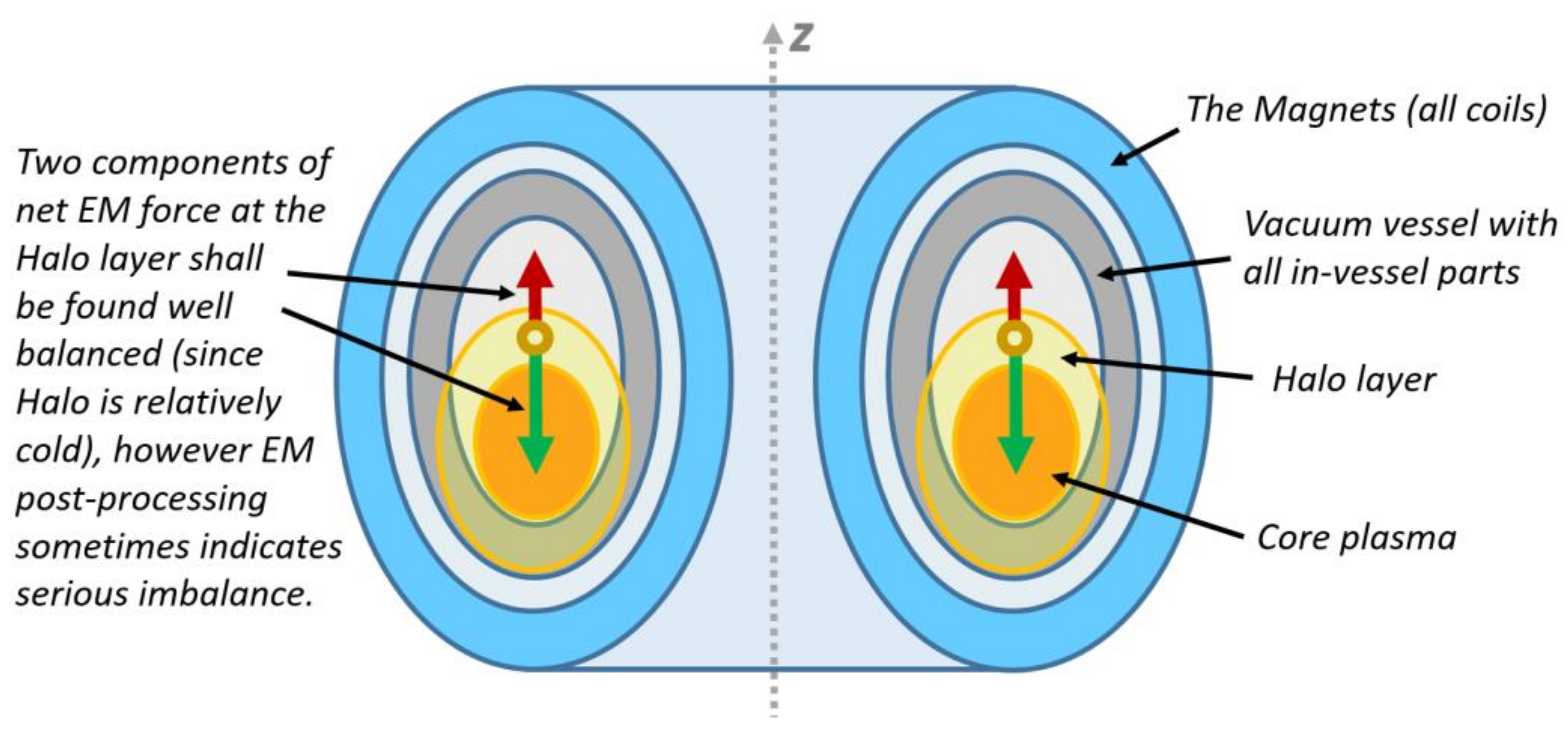
Figure 1 illustrates the two main components in a balance of net EM loads at the Halo layer.
There can be two situations:
- If a model of the Halo layer is such that a well-working code delivers practically zero net EM load at the Halo layer, then the code delivers practically zero net EM loads at the entire tokamak and accordingly well-balanced opposite net EM loads between VV and the magnets.
- However, if a model of the Halo layer is such that a well-working code delivers far-from-zero net EM load at the Halo layer, then it delivers the following:
- Still practically zero net EM loads for the entire tokamak as the closed EM system;
- However, imbalanced net EM loads between VV and the magnets—by the same degree as they are found imbalanced for the Halo layer.
A careful reader will ask to simulate the MHD equilibrium of the Halo layer, taking into account the gradient of plasma pressure through the Halo layer. This is correct but looks to be a minor factor since the Halo plasma is much colder than Core plasma. This factor cannot disturb the global EM load balance for the tokamak since it is compensated locally (between the Halo and Core plasmas). Specific simulations can track this load component. Here, it is enough just to mention it.
It is clear that the degree of the imbalance of net EM loads at the Halo layer is a function of the helicity of the Halo current. This means the way to reduce the imbalance is through adjustment of the helicity of the Halo current at each time instance. In other words, the helicity of the Halo current must be iterated to lead to a sufficiently low remaining imbalance of the net EM loads at the Halo layer. This is the main message of this section, and the following text just adds details and explanations.
Typically, the linked plasma and EM transients are simulated with the sequential use of two codes. A code simulating the detailed plasma equilibrium and transients consistent with simplified 2D models of VV and major coils, e.g., [8], and a 3D EM postprocessing code delivering a pattern of distributed EM loads in 3D structures of VV with ports, in-vessel components, coils windings, and cases, e.g., [9]. Both codes can contribute to the remaining imbalance of net EM loads to the Halo layer as follows:
- If the plasma evolution code does not assure a balance of EM loads to the Halo layer, it delivers waveforms of toroidal vs. poloidal currents in the Halo layer with a mutual mismatch already embedded. Then, even an ideal EM postprocessing code will reproduce the same mismatch for the Halo layer and accordingly will deliver imbalanced net EM loads between VV and the magnets.
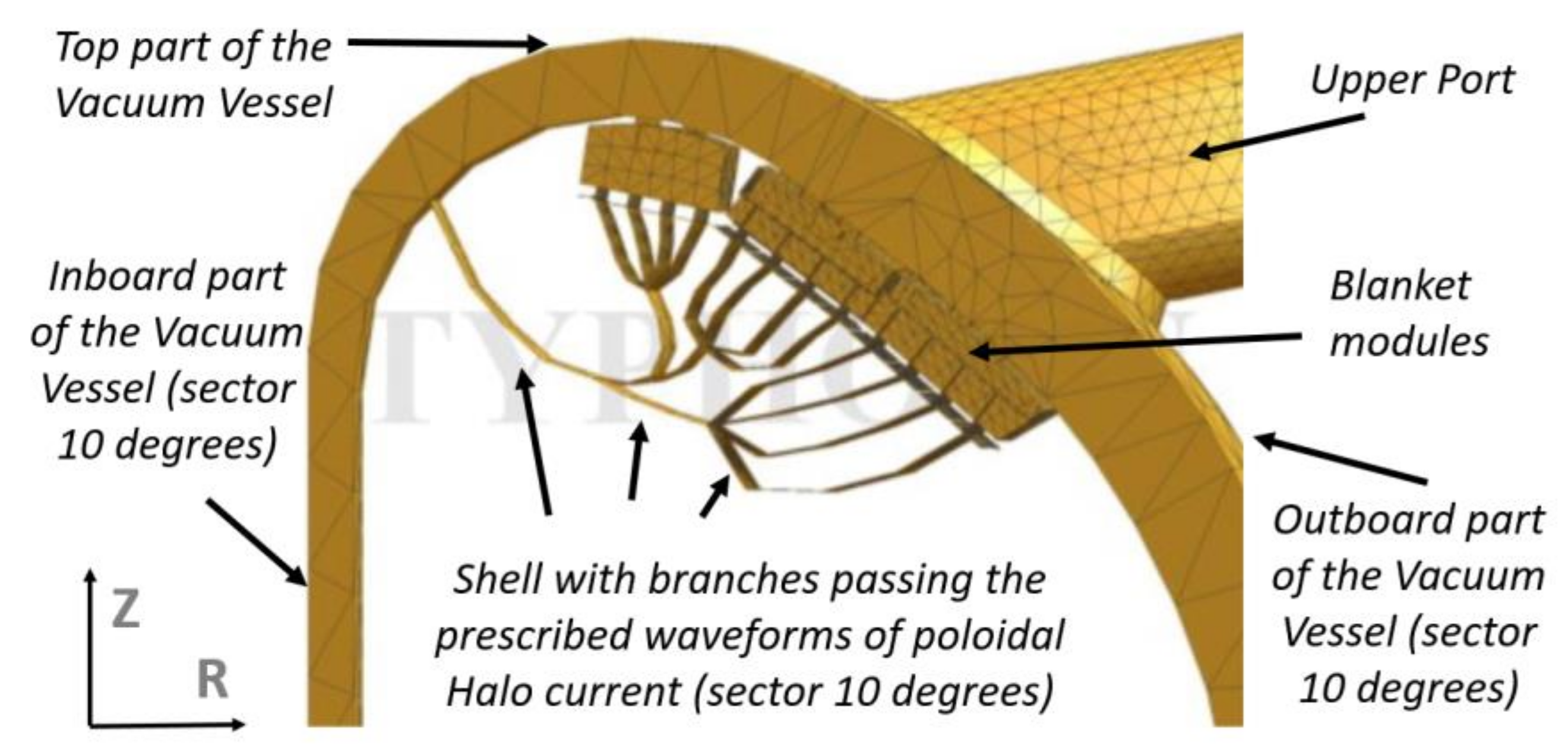
- A mismatch happens also at the postprocessing stage, due to the simplified “stepped-in-time” output of plasma simulation codes for the Halo layer’s “wetted” areas and due to the rather schematic model of the Halo layer in the postprocessing codes. Typically, since ITER EDA times [3], the Halo layer is simulated by either one or a few conductive shells (Figure 2) fixed in space and carrying the prescribed waveforms of only poloidal Halo current, since the toroidal component is already included in output files of plasma simulation codes. When the Halo layer is modelled by a few enclosed or branching shells, the prescribed waveform of poloidal halo current gradually migrates from the outer shells to the inner ones.
The author believes that the two described reasons combine. They both contribute to the remaining misbalance of net EM loads in VV and the magnets, thus both should be treated.
Summary of Section 3: the author would make the following recommendation. All reports devoted to the pulsed EM loads at VV and the magnets should make clear to which object each reported load component or net vector applies: either to VV or to the magnets, or this is just one of the components of EM loads on the plasma contributing to a zero net total for the plasma. Detailed EM models can distinguish net loads for several EM-loaded objects: For example, each major coil may count as separate EM-loaded object with the delivery of net EM load vectors for each of them.
If and when EM postprocessing for VDE- or AVDE-induced loads concludes with a serious imbalance of net EM loads between VV and the magnets, this the most likely an indicator for a poor match of waveforms of toroidal and poloidal Halo currents in one or both of the involved codes. For engineering purposes, to obey the first principles, such imbalance must be properly compensated prior to the delivery of transient EM load patterns for design purposes. A way to balance EM loads at the Halo layer, and consequently between VV and the magnets, is through iterations of the helicity of the Halo layer at each time instance aimed to simulate this layer practically EM-force-free or, more accurately, to obey its MHD equilibrium.
It would be good if all involved codes provided automated monitoring and comparing of net EM load vectors at least for VV, the magnets, and plasma (including the Halo layer), and verified a total for the entire tokamak. If and when EM postprocessing indicates a significant imbalance between net EM loads at VV and the magnets, this finding to be conducted to a team running plasma evolution code with the suggestion to check net EM force balance for the Halo layer. Then, the described above corrective action can be undertaken.
4. EM-Induced Dynamic Response Can Amplify Reaction Forces at VV and Magnet Supports
The final result needed for the engineering purposes is not just “direct” transient EM loads applied at VV (distributed and net vectors) and mirrored as net EM loads for the magnets, but also the so-called dynamic (direct EM plus inertial) interface loads acting at various supports and links (e.g., [6,7]). In many tokamaks, inertial components of VDE-induced reaction forces in VV and magnet supports have a scale similar to direct EM loads. In some tokamaks, VV and magnet supports are designed such that the inertial loads are not compensated well enough. Such tokamaks behave as “open systems” for inertial loads, and their dynamic models shall describe the tokamak and a significant part of the building.
This paper skips deeper details on this subject. It is enough to say that EM and inertial VDE-induced loads for the vacuum vessel are usually available; however, the matching EM and inertial loads for the magnets, as well as VDE-induced dynamic loads “internal to the magnets” are sometimes omitted. One of the purposes of this article is to assure that future studies will report both components.
In tokamaks with superconducting coils, the vacuum vessel thermal shield (VVTS) rests either on VV or the magnets. Accordingly, simulations of the VVTS dynamic response to VDE- or AVDE-induced loads shall use as input EM-induced vibrations of VV or the magnets (e.g., as floor response spectra).
In tokamaks where the supports are not designed to effectively compensate the dynamic loads between VV and the magnets, differential effects of VV and magnet vibrations can cause significant cyclic inertial forces in interfaces of the tokamak to the building. Being design dependent, these interface loads allow some reduction “by design.” For example, it is worth designing supports in a way, which assures accurate mutual intersection of opposite pulsed force vectors applied through VV and magnet supports.
Summary of Section 4: simulation of EM-induced dynamic (EM plus inertial) response of VV and the magnets (and the building) is a must in VDE and AVDE studies. Several studies offer dynamic results during VDEs for the VV with in-vessel parts, however, rarely for the magnets, building, and the VVTS resting either on the VV or the magnets.
5. Bell-Like Vibrations of VV Structure Accelerate Ramp up of Reaction Forces in VV Supports
Our reader knows that VDE-induced EM transients in the poloidal fields penetrate through the VV walls faster than the decay time of a uniform toroidal eddy current in VV. This is because VDE induces also “multipole” toroidal currents in VVs that have shorter decay times, approaching the typical duration of the plasma current quench (CQ). Accordingly, self-consistent plasma and EM simulations for VDEs show that transient net EM forces at VV and the magnets ramp up with a characteristic time of the order of the CQ time.
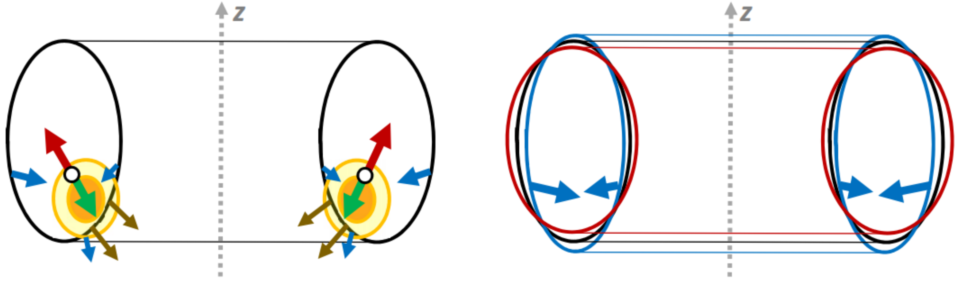
This section highlights additional reasons for accelerated ramp-ups of reaction forces in VV supports. This effect is caused not by total EM loads but by a specific distribution of EM force density at the VV walls (called here “EM pressure”). Our reader knows that “EM pressure” at VV walls builds up fast during the CQ, peaks right at the end of the CQ, and applies mostly at two toroidal belts located close to the inboard and outboard VV equators (slightly above equators for VDE Up and slightly below for VDE Down). In both equatorial belts, EM pressure acts towards the plasma axis, as illustrated by Figure 3.
The bidirectional horizontal components of the magnetic pressure at the VV structure cannot contribute to the balance of net vertical EM forces; however, they deform the VV cross section, which slightly shifts inward, shortens in the radial direction, and accordingly elongates in the vertical direction (Figure 3). These components of EM loads, being internal to VV, grow with the CQ time scale and accordingly generate bell-like vibrations of the VV structure. This effect was mentioned for the ITER EDA, and seen well in recent dynamic simulations illustrated in next section.
Since the massive VV tends to keep its centre of mass in place, if it is supported at the bottom, the described VV vibrations apply additional cyclic reaction forces at the VV supports. These lead to the reaction forces growing faster than the net EM forces between VV and the magnets and thus seriously accelerate the tokamak dynamic response to fast EM events. This effect causes the rather fast vertical and radial shift of the top points of VV This shift takes about a quarter of a period of main modes of bell-like VV vibrations, and the first peak is reached almost at the end of CQ. Ramp-up of resultant inertial loads in VV supports is decoupled from decay times of eddy currents in VV.
In terms of the global dynamic balance in the interface between the tokamak and the building, inertial forces in the VV supports are compensated partly by reaction forces passing through the magnets supports, and partly by inertia forces in the tokamak-to-building interface. The specific sharing between the listed load paths depends on their dynamic characteristics. Particularly, the described above inertial loads at VV supports can cause similar (but smaller) inverse inertial loads in the magnets supports.
Summary of Section 5: Surprisingly fast ramp-up of the cyclic reaction forces at VV supports is not a numerical error but a real effect caused by bell-like vibrations of the VV structure initiated by a pulse of EM pressure in the vicinity of both VV equators at the end of CQ. Schemes with VV supports located at the bottom of VV maximise such additional inertial loads. Alternatively, schemes with VV supports that are lifted to some degree towards the horizontal plane passing through the centre of the mass help to suppress it.
6. Even Symmetric VDE Causes Some Lateral Inertial Loads in Mechanically Asymmetric Tokamaks
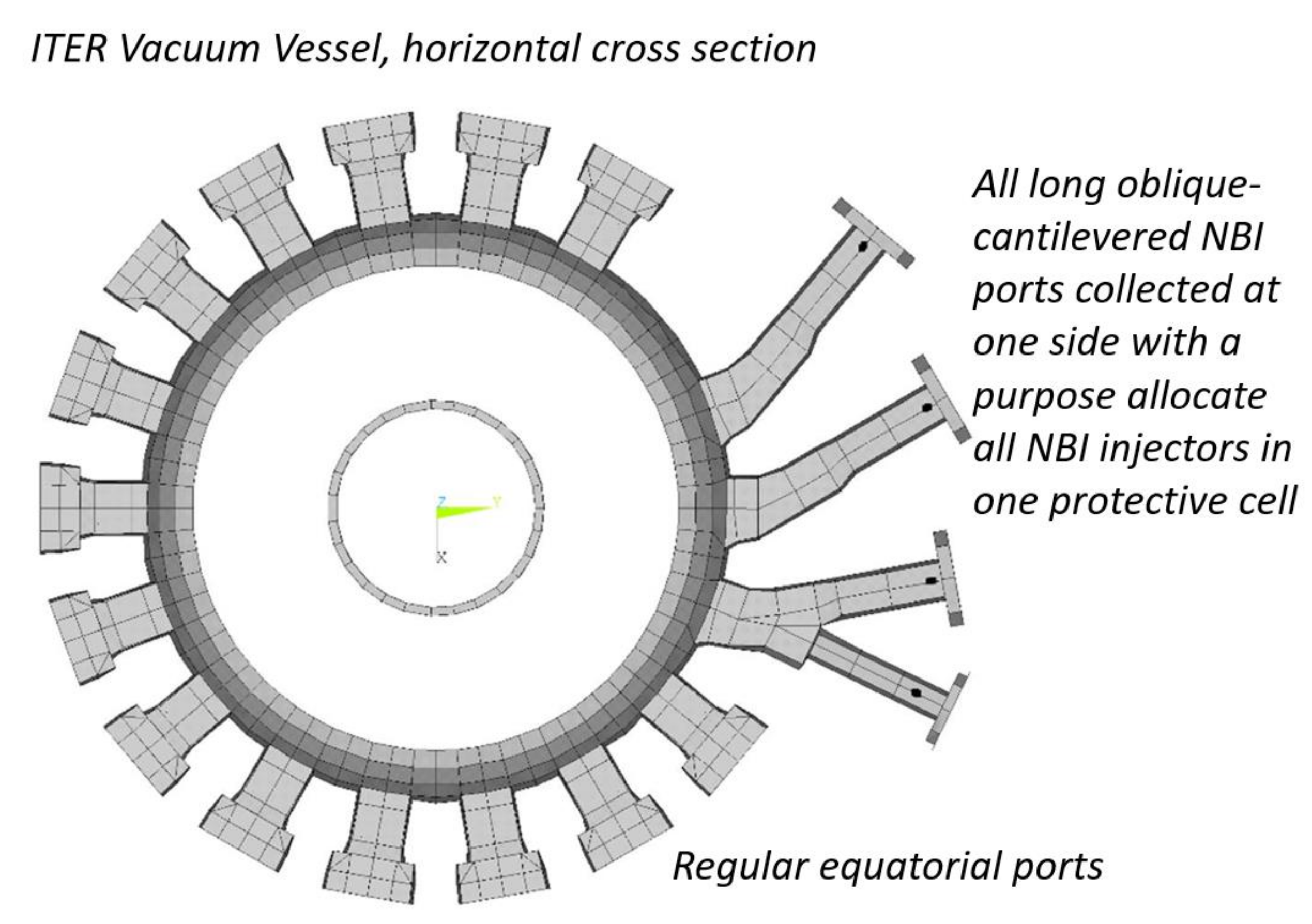
In large tokamaks, several long oblique-cantilevered ports for neutral beam injection heating (NBI ports) are usually located toroidally in one side of the tokamak (Figure 4) since injectors are directly connected to the torus and need to be contained in a protective cell. This makes the VV slightly asymmetric in terms of dynamic response. In such tokamaks, even perfectly symmetric EM excitation at VDE causes the combined vertical and lateral VV oscillations. Since typical tokamak’s structures are the most rigid for vertical loads but less rigid for lateral and torsional loads, even a slight mechanical asymmetry associated, e.g., with NBI ports leads to quite a noticeable asymmetry in the dynamic response of VV, and this gradually excites lateral oscillation of VV ports and other parts.
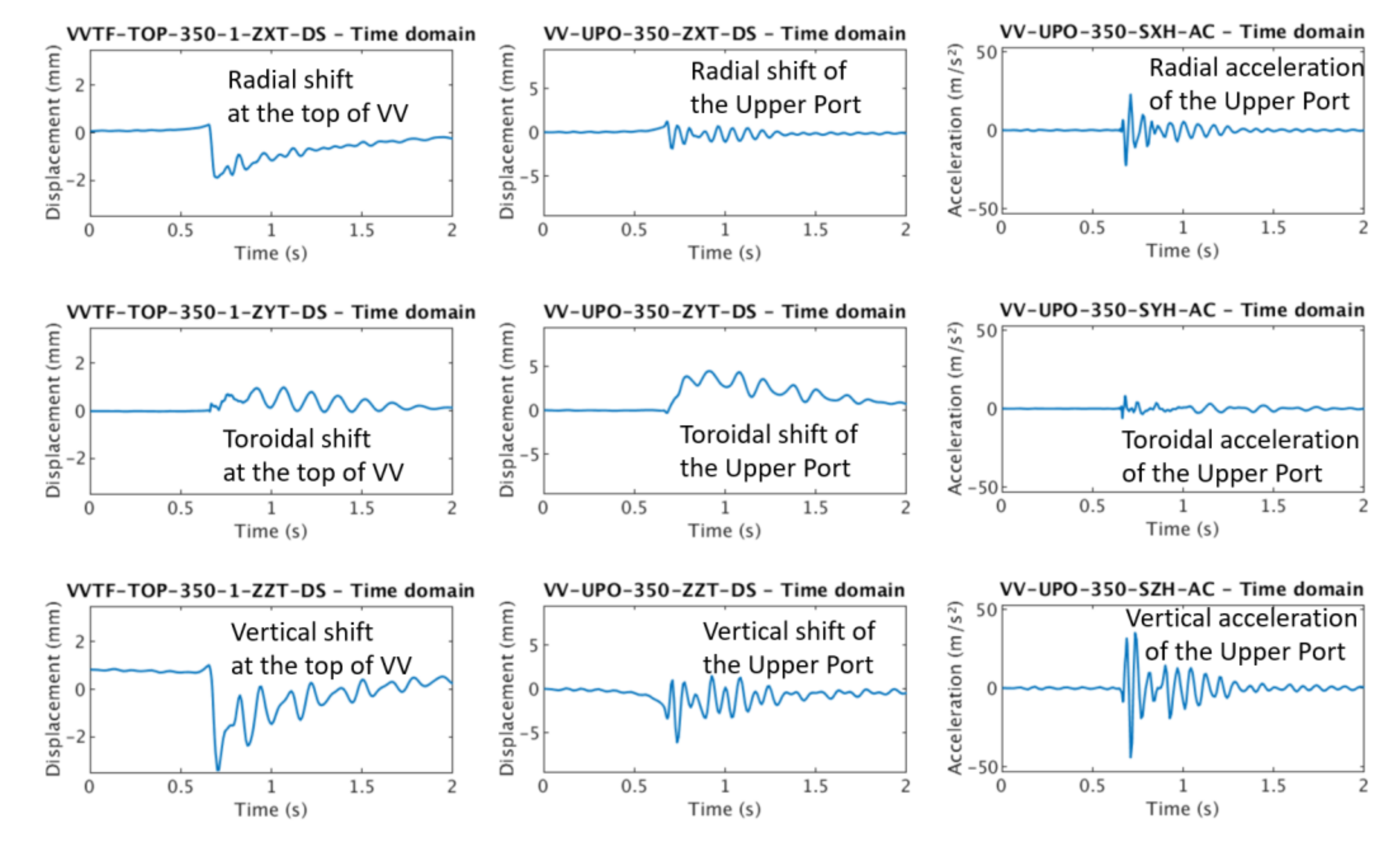
Figure 5 [7] demonstrates rather different dynamic responses of VV in two spots: at the top of the VV and at the end of the regular upper port (both at one azimuth). These plots prove that bell-like vibrations of the VV structure play quite a large role in the overall VV dynamic response to EM loads and can gradually excite significant lateral oscillations of VV ports. This article does not delve into deeper detail since it leaves a systematic presentation of quantitative results to the currently working teams [6,7].
The described above asymmetric inertial effect at VDE resembles tokamak’s dynamic response to AVDE-induced lateral EM loads. When AVDE actually develops, two contributors become mixed. For a fast-rotating AVDE, they can be distinguished by frequencies. However, they can be difficult to distinguish for slow rotating or locked AVDE. Then, the way is to separate inertial and AVDE loads by analysis.
Figure 5 shows that vertical VV oscillations grow fast, approximately at the time scale of CQ, but lateral oscillations grow gradually and peak at 200–300 ms after the end of CQ (these results are for a large tokamak). Both vertical and lateral motions in Figure 5 have aperiodic and periodic components. Since they are for symmetric EM excitation but slightly asymmetric mechanical design, we can state that aperiodic component of all displacements correlates with direct EM loads: with ramp-ups and decays of eddy currents in VV; lateral aperiodic component indicates the asymmetric inertial response of the tokamak to symmetric EM excitation; and all periodic components represent the inertial response.
Summary of Section 6: in tokamaks with some mechanical asymmetries, e.g., with NBI ports packed at one side, even ideally symmetric EM excitation (VDE) causes a mix of vertical, radial, and lateral oscillation modes. Such tokamaks demonstrate an asymmetric dynamic response to even perfectly symmetric plasma events. Vertical and radial modes reach their peaks rather fast, almost at the end of CQ, but lateral oscillations of some parts in some tokamaks can gradually grow for a long time after CQ. Since excitation of lateral modes is design dependent, this effect can be seen well in some tokamaks but masked in others. It depends on the rigidity of tokamak structures for different oscillation modes, degree of mechanical asymmetry and EM damping effects, etc. It depends also on the characteristics of specific VDEs: slow or fast, upward or downward.
Committed to points of the engineering understanding still gained at ITER EDA times, this article does not delve into details of present EM and dynamic simulations of VDE and AVDE. It leaves these to currently working teams of analyses.
7. Conclusions
The author considers that the presently discussed significant scatter of available estimates for lateral AVDE-induced forces in different studies can partly be explained by comparing the following different items:
- Net EM load vectors at VV, the magnets, or just one component for the plasma;
- Reaction forces in VV or magnets supports found either with or without inertial effects;
- The same either with or without cyclic interface loads added by VV bell-like vibrations;
- Either with or without taking into account the asymmetric inertial response of some tokamaks to even perfectly symmetric EM excitations, etc.
With respect to each discussed EM load, it is always worthwhile to indicate the object it applies to, whether it is a net vector EM load or just a component contributing to the net load, direct EM load, dynamic load, etc.
Codes used in VDE and AVDE studies shall monitor the balance of net EM loads at two EM-loaded objects, VV and the magnets, which interact through EM-force-free link, namely, the plasma and its Halo layer. Such monitoring can be carried out through calculation of the net EM loads for VV and the magnets, which are supposed to be found mutually balanced, and also for the entire tokamak and the plasma with the Halo layer, both of which are supposed to be close to zero by the definition. Both can serve as indicators of simulation quality.
The way to assure the proper balance of opposite transient net EM load vectors between VV and the magnets is through adjustment of the helicity of the Halo current at each time instance with, as a criterion, low enough residual net EM load for the entire Halo layer. This automatically restores the balance of transient net EM loads between VV and the magnets.
Numerical simulations of VDE- and AVDE-induced loads (direct EM plus inertial) should deliver dynamic reaction forces and torques applied not only to the VV supports. They should also include the matching dynamic reaction forces and torques acting to the magnets supports as well as in interfaces internal to the magnets and between the tokamak as a whole and the building in which the tokamak is installed.
Since the vacuum vessel thermal shield (in tokamaks with the superconducting coils) rests at either VV or the magnets, simulations of the thermal shield dynamic response to MD, VDE, or AVDE should employ EM-induced vibrations of VV or magnets as an input.
Dynamic characteristics of VV and magnets supports are design dependent. Well-considered design of the tokamak supports can compensate to some degree VDE- or AVDE-induced inertial forces.
Even a slight mechanical asymmetry of some tokamaks (e.g., by NBI ports grouped at one side) may cause noticeable lateral oscillations of VV and then amplified lateral oscillations of VV ports, etc. Amplitudes of lateral oscillations of VV ports and other parts can grow quite a long time after the end of CQ. Similar dynamic excitation is anticipated for some coils relative to others inside the magnets.
The author expresses sincere acknowledgements to ITER CDA and EDA experts, namely, Y. Shimomura, V. Mukhovatov, A. Loarte, D. Thome, J. Wesley, P. Barabaschi, and many others for friendly informal exchange by ideas which formed the described above points of the engineering understanding.
The views and opinions expressed herein do not necessarily reflect those of the ITER Organisation.
Funding
This research received no external funding.
Institutional Review Board Statement
Not applicable.
Informed Consent Statement
Not applicable.
Data Availability Statement
Not applicable.
Conflicts of Interest
The author declares no conflict of interest.
References
- Shimomura, Y.; Wesley, J.; Astapkovich, A. ITER Poloidal Field System; IAEA: Vienna, Austria, 1991. [Google Scholar]
- Sadakov, S.; Fauser, F.; Nelson, B. ITER Containment Structures; IAEA: Vienna, Austria, 1991. [Google Scholar]
- International Atomic Energy Agency (IAEA). Final Report of the ITER EDA. Final Report of the ITER Engineering Design Activities Prepared by the ITER Council (IAEA-ITEREDA/DS-21); IAEA: Vienna, Austria, 2001. [Google Scholar]
- Astapkovich, A.M.; Doinikov, N.I.; Komarov, V.M.; Korshakov, V.V.; Sadakov, S.N. Numerical modeling of the plasma disruption in a tokamak with self-consistent plasma evolution. Vopr. At. Nauk. I Tech. Ser. Thermonucl. Synth. CNNIIAtominform 1988, 4, 9–15. [Google Scholar]
- Glukhikh, M.I.; Sadakov, S.N. Plasma Quest code for pulse scenario synthesis and transient electromagnetic studies in tokamaks. Plasma Devices Oper. 2003, 1, 57–70. [Google Scholar] [CrossRef]
- Schioler, T. (ITER, Saint-Paul-lez-Durance, France); Ruiz; P. Private communications. Memo of EM-loaded tokamak machine model for TSM task#3, 2019.
- Maqueda, L.; (Esteyco Mechanics, 28036 Madrid, Spain); Villone, F.; (Universita degli studi di Cassino at del Lazio Meridionale, Cassino, Italy). Private communications, 2021.
- Lukash, V.; Gribov, Y.; Kavin, A.; Khayrutdinov, R.; Cavinato, M. Simulations of ITER scenarios. Plasma Devices Oper. 2005, 13, 143–156. [Google Scholar] [CrossRef]
- Belov, A.; Gapionok, E.; Gornikel, I.; Kukhtin, V.; Lamzin, E.; Neubauer, O.; Sytchevsky, S. Electromagnetic transient simulation using a shell approach for ITER CXRS upper port plug due to plasma vertical displacement events. Fusion Eng. Des. 2010, 86, 1920–1923. [Google Scholar] [CrossRef]
Figure 1.
Green arrow: toroidal current component in the Halo layer interacts with toroidal currents in CS and PF coils, and with toroidal components of 3D currents in VV. This force pushes the Halo layer to the Core plasma. Red arrow: poloidal current component in the Halo layer interacts with currents in TF coils and with poloidal components of 3D currents in VV. This force pushes the Halo layer out of the Core plasma. In physical sense, these two components should almost compensate each other (the Halo layer shall be in MHD equilibrium); however, this is not always the case in numerical results.

Figure 2.
Since ITER EDA times [3], many EM postprocessing codes, e.g., [9], simulate the Halo layer as either one, or a few enclosed, or branching shells fixed in space and time and fed by waveforms of poloidal Halo current delivered by plasma evolution code. There is an example of the branching shell. This illustration is courtesy of authors [9].

Figure 3.
Schematic illustration of EM loads at VV during and after CQ: left side illustrates EM loads when plasma with the Halo layer still exists. Red arrow: interaction of poloidal halo current with toroidal field; green arrow: toroidal halo current with poloidal field; brown arrows: poloidal halo current in VV with toroidal field; blue arrow: toroidal currents in VV with poloidal field. Right side: blue arrows show “magnetic pressure” at VV due to interaction of toroidal currents in VV with poloidal field when plasma and the halo layer disappeared. The magnetic pressure causes slowly growing vertical net force at VV, but much faster it deforms VV structure, as shown by blue contour (relative black contour). Then VV vibrates, as shown by all three contours at the right. Since massive VV tends to keep its centre of mass in place, these vibrations add cyclic inertial forces at VV supports.

Figure 4.
Long oblique-cantilevered NBI ports collected at one side of large tokamaks by design reasons cause an asymmetric dynamic response of VV to even perfectly symmetric EM excitation at VDE. This plot is from visual library of ITER IO.
Figure 4.
Long oblique-cantilevered NBI ports collected at one side of large tokamaks by design reasons cause an asymmetric dynamic response of VV to even perfectly symmetric EM excitation at VDE. This plot is from visual library of ITER IO.

Figure 5.
Dynamic simulations [7] demonstrate rather different characteristics of VV dynamic response in different spots: at the top of the VV and at the end of the regular upper port, both at one azimuth. This indicates a large role of bell-like vibration of VV structure. Vertical and radial aperiodic components associate mostly with direct EM loads, while lateral aperiodic- with asymmetric inertial response to symmetric EM excitation, and all periodic components- with various modes of inertial response. Courtesy of [7].

Publisher’s Note: MDPI stays neutral with regard to jurisdictional claims in published maps and institutional affiliations. |
© 2021 by the author. Licensee MDPI, Basel, Switzerland. This article is an open access article distributed under the terms and conditions of the Creative Commons Attribution (CC BY) license (https://creativecommons.org/licenses/by/4.0/).
Share and Cite
MDPI and ACS Style
Sadakov, S. A Few Points of the Engineering Logic Discussed in ITER EDA on Evaluation of Halo- and AVDE-Induced Loads in Tokamaks. Plasma 2021, 4, 366-374. https://0-doi-org.brum.beds.ac.uk/10.3390/plasma4030025
AMA Style
Sadakov S. A Few Points of the Engineering Logic Discussed in ITER EDA on Evaluation of Halo- and AVDE-Induced Loads in Tokamaks. Plasma. 2021; 4(3):366-374. https://0-doi-org.brum.beds.ac.uk/10.3390/plasma4030025
Chicago/Turabian StyleSadakov, Sergey. 2021. "A Few Points of the Engineering Logic Discussed in ITER EDA on Evaluation of Halo- and AVDE-Induced Loads in Tokamaks" Plasma 4, no. 3: 366-374. https://0-doi-org.brum.beds.ac.uk/10.3390/plasma4030025