1. Introduction
Recent explosions in Beirut, Lebanon [
1], Baltimore, MD, USA [
2], and Ajman, UAE [
3], which all occurred within one week in August 2020, and claimed numerous lives and expensive properties, reinitialize the importance of fire safety, with a focus on scrutinizing of the nature of the explosions. Specifically, understanding the dynamics of an accidental gaseous explosion would provide a way to develop innovative solutions to prevent subsequent explosions. These novel solutions can help to reduce the frequency of occurrence and mitigate the impacts of an explosion. This is a vital research area, since fossil fuels are still much employed in everyday lives at homes, offices, and industries, which sometimes requires storing them in small quantities.
Explosion venting has been a way of suppressing the drastic effects of an accidental explosion by reducing the maximum overpressure in the enclosure. Earlier studies on this topic have spanned from the works of Bradley and Mitcheson [
4,
5] to that of Mulpuru and Wilkin [
6], along with subsequent collaborative efforts to develop a model predicting the dynamics of explosion for a hydrogen-air mixture. Other empirical models developed to predict the pressure evolution as well as the peak overpressures in an enclosure included (though not limited to) the FM Global models by Bauwens et al. [
7,
8,
9], which were based on the experimental works on hydrogen and hydrocarbon explosions. In particular, it has been suggested that external explosion, flame-acoustic interaction, and the flame wrinkling caused by obstacles are responsible for the multiple peak overpressures noticed in the pressure history. Molkov and Bragin [
10] also developed a model predicting peak overpressure for vented hydrogen-air explosion based on the turbulent Bradley number, which was presumed to correlate with the overpressure in an enclosure. Sinha et al. [
11] have developed another model predicting vented hydrogen-air explosion, based on the external cloud formation and explosion. In another work of the same team, a simple model was created to predict the peak pressure in the vented explosions of hydrogen-air and hydrocarbon-air mixtures [
12]. Here, simplifying assumptions were employed to generate a single equation to predict the overpressure in the vented explosions based on four parameters: two of these parameters depended on the fuel properties, which could be pre-calculated, while the other two were functions of the enclosure geometry. Such a reduced simple model minimizes the numerical efforts needed to estimate the maximum overpressure resulting from the gas explosion in an enclosure. The experimental works [
7,
8,
9,
13,
14,
15,
16,
17,
18] on hydrogen-air, hydrocarbon-air, and natural-gas-air explosions, employing various geometries and conditions, have been used to validate some of the models predicting the dynamics of gaseous explosions. The drawbacks of an explosion experiment, which includes requiring ample time, difficulty in setting-up an experiment, coupled with severity associated with the experiment in the case of an accident, actually makes it a dangerous venture. Computational Fluid Dynamics (CFD) applications were also used in modelling gaseous explosions [
19], but they also required a lot of computational time and resources.
To reduce such a demands in the computational time and costs, Ugarte et al. [
20] developed and coded a reduced-order transient model named the Explosion Venting Analyzer (EVA), which was built-up on the earlier explosion predicting model equations [
6] and is able to promptly predict hydrogen explosions in spheres, cuboids, and cylindrical geometries. A subsequent work by Sezer et al. [
21] extended the EVA to predict hydrocarbon (methane and propane) explosions. It should be noted that the EVA has undergone various modifications for better prediction accuracy, including the formulations for the flame shape and the burning velocity as well as the addition of the new enclosure geometry. While Sezer et al. [
21] validated and established the EVA capability of predicting hydrocarbon explosion experiments in a cuboid enclosure, later, the experimental work of Kodakoglu et al. [
22] analyzed methane-air explosions in a cylindrical geometry. Therefore, the present work extends and employs the EVA to model the conditions and geometry of Ref. [
22], which resembles a typical configuration of tubes and pipelines used for the natural gas supply. Specifically, the pressure evolution and peak pressure results from the EVA are tabulated and validated by the experimental data [
22] in order to ascertain the accuracy of the EVA prediction in this geometry.
It is noted that the flame velocity model embedded in the EVA is based on the experimental correlations for a specific fuel mixture composition and its range of equivalence ratios. While the EVA can predict the explosion dynamics for various fuel mixtures, experimental correlations for the flame speeds are usually not available for most fuel mixtures, which therefore limits the EVA. Therefore, to fix this uncertainty, the Cantera package [
23] is integrated with the EVA to compute the flame speeds, with the results being in good agreement with the available experimental correlations. As a result, by integrating Cantera with the EVA, the earlier limitation of the EVA usability, being restricted to a small range of the fuel mixture compositions and equivalence ratios, is removed.
In the present study, a physics-based phenomenological tool that can potentially simulate the explosion dynamics of any fuel mixture composition and its equivalence ratios is developed. This transient reduced-order model predicting explosions can then be utilized to determine the maximum overpressure when designing safety vents employed to mitigate the consequences of explosions.
2. Model Description
The mathematical model employed in this work, the EVA, was developed by Ugarte et al. [
20] and it has undergone several modifications as mentioned in Ref [
21]. The EVA is a transient, reduced-order model used to predict the maximum (over)pressure, the mass transfer, and the flame speed during explosions in vented and unvented enclosures. The EVA is capable to estimate the explosion characteristics in various geometries by solving the mass and energy balance equations, along with the burning rate formulations, as summarized below.
Here,
and
stand for the time and mass, respectively, the subscripts
, and
designate the unburned, burned, vented, and initial conditions,
is instantaneous-to-initial pressures ratio,
is the initial volume occupied by the burnt gas, and
represents the specific heat ratio of the unburnt gas, employed from the NASA-CEA solver [
24] embedded in the EVA to calculate the thermal-physical properties of the respective fuel-air mixtures.
The burning rate formulation:
Equation (3) determines the rate at which the burnt matter is generated, as a function of the burning velocity with respect to the fuel mixture denoted as , the surface area of the flame front , and the initial volume of the fuel mixture denoted as . The term in Equation (3) is used to specify the type of gas vented, with if the unburned gas is vented, and if the burnt gas is vented.
Here,
is specific energy of formation, along with the reference temperature
, the specific heat at constant volume
, and the specific heat ratio of the burnt gas
. Further details of the original EVA model are given in Refs. [
20,
21].
2.1. Models for the Flame Shape
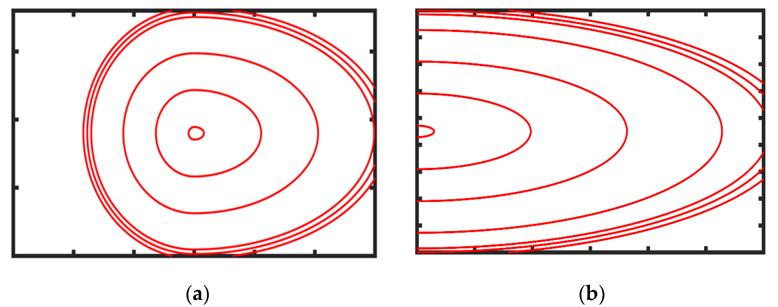
The flame shape is one of the major parameters imposed into the EVA solver, being either spherical or ellipsoidal. The latter is one of the modifications made to the original EVA platform. It is noted that the pioneering Mulpuru–Wilkin predictive explosion model [
6] considered a spherical flame shape. Such a choice was suitable to predict the explosion dynamics in the configuration used in the experimental work, as there was good match between the experimental work and the model. However, for most geometries, the spherical flame assumption is not accurate, leading to a notable discrepancy between the results of the predictive explosion model as compared to the experimental results.
According to Ref. [
21], the flame shape influences the maximum peak pressure values as well as the explosion behavior. In particular, the ellipsoidal shape of the flame front in Ref. [
21] provided better predictions of the explosion characteristics in the cylindrical geometry as compared to the spherical flame shape. Therefore, in the present work, where a cylindrical geometry is being considered, the ellipsoidal flame shape, illustrated in
Figure 1, is used. The fuel-air mixture for this work was ignited at the rear end far away from the vent area.
Figure 1b therefore depicts the flame shape behavior in this study better.
2.2. Calculation of the Flame Speed
The laminar burning velocity
is a key parameter used in predictive models characterizing explosions. Consequently, accurate determination of the value
yields a substantial effect on the accuracy of the results of the predictive model. When a particular
-value is not available, it is computed in the EVA by using the correlation formula [
25,
26]
as a function of unburnt gas temperature,
, and pressure,
, scaled by their initial values
and
. Here
is the laminar burning velocity at the initial temperature and pressure,
, while the exponents
and
are usually functions of the fuel-to-oxidizer equivalence ratio
. Stone et al. [
25] suggested the following relations for the methane-air mixtures:
As a result, in the present work, we use Equations (6) and (7) to calculate .
Another approach used in earlier works [
27,
28] to calculate the burning velocity is to employ a combustion modeling software such as Cantera—an open-source chemical kinetics software having various available chemical kinetics model, embedded into it, to compute
. Specifically, Cantera identifies the laminar burning velocity through modelling a one-dimensional (1D) freely propagating laminar premixed flame front. Then the laminar flame speed is calculated as [
29,
30]
where
is the density of the unburnt gas, while the quantity
for the mass flux through a freely propagating flame is calculated according to Ref. [
31]. Further details regarding how Cantera calculates the flame speed for various fuel-oxidizer mixtures can be found in Refs. [
29,
30,
31].
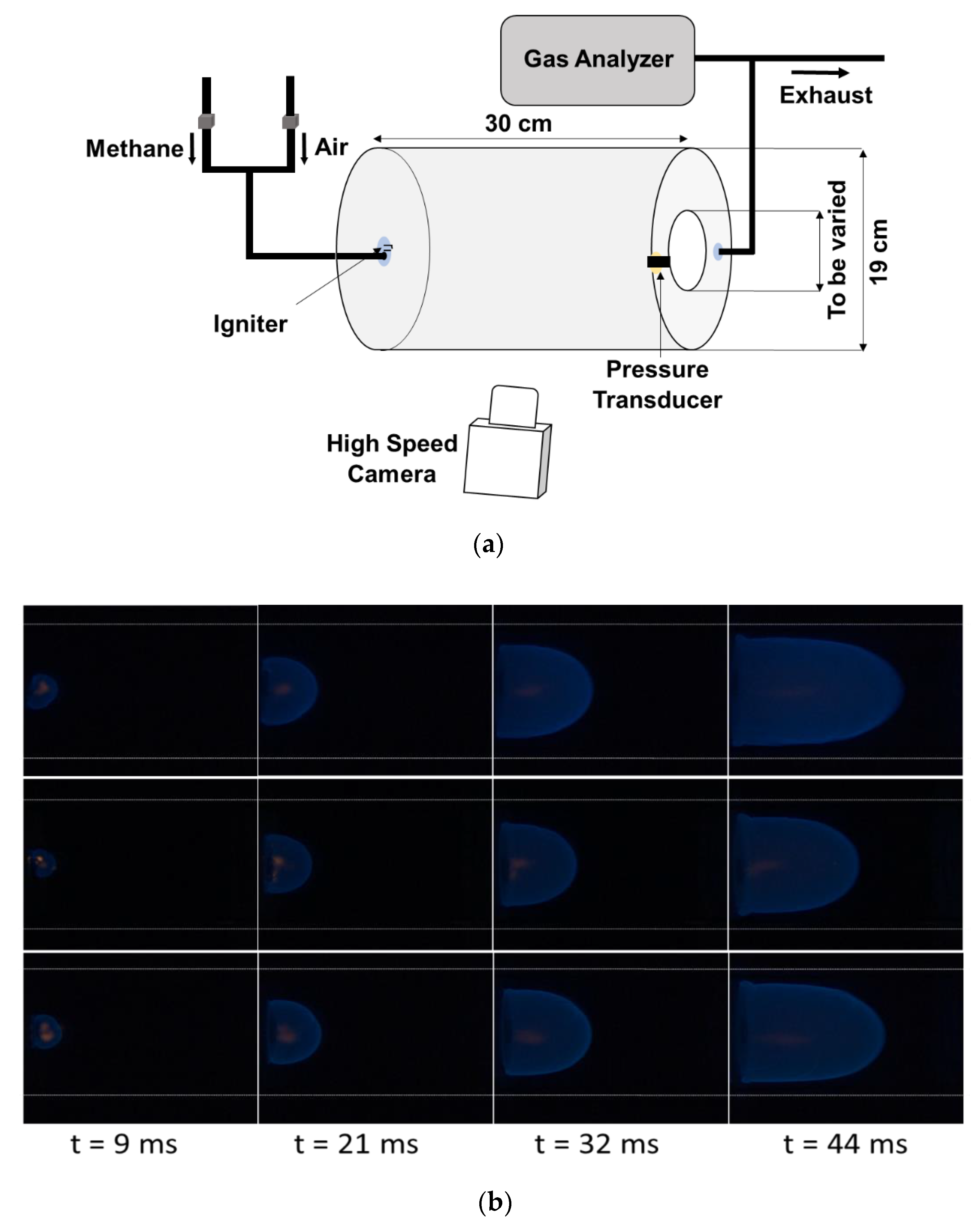
2.3. Description of the Experimental Set-Up
We next briefly describe the experimental setup and conditions of Kodakoglu et al. [
22], which are simulated in this present study using the EVA solver. Specifically, the EVA results for fuel-lean (
), stoichiometric (
), and fuel-rich (
) methane-air mixtures were compared with the experiments for rear ignition occurring in a cylindrical chamber having the diameter of 19 cm and the length of 30 cm such that the internal volume was 8,505.6 cm
3. Three various circular venting openings have been considered, namely: a small vent (SV) of the venting area 67.9 cm
2, a medium vent (MV) of area 88.6 cm
2, and a large vent (LV) of area 132.7 cm
2. The experiments [
22] are illustrated in
Figure 2. Specifically,
Figure 2a shows a schematic of the experimental setup. Here, the front panel accommodates the vent while the rear panel is used for injection of the gas mixture and ignition probes. The vent was covered with a thin foil layer and was cut prior to ignition.
Figure 2b presents evolutions of the elliptic flames for all three vents considered; see the top, middle, and bottom rows for the small, middle, and large vents, respectively.
3. Results and Discussion
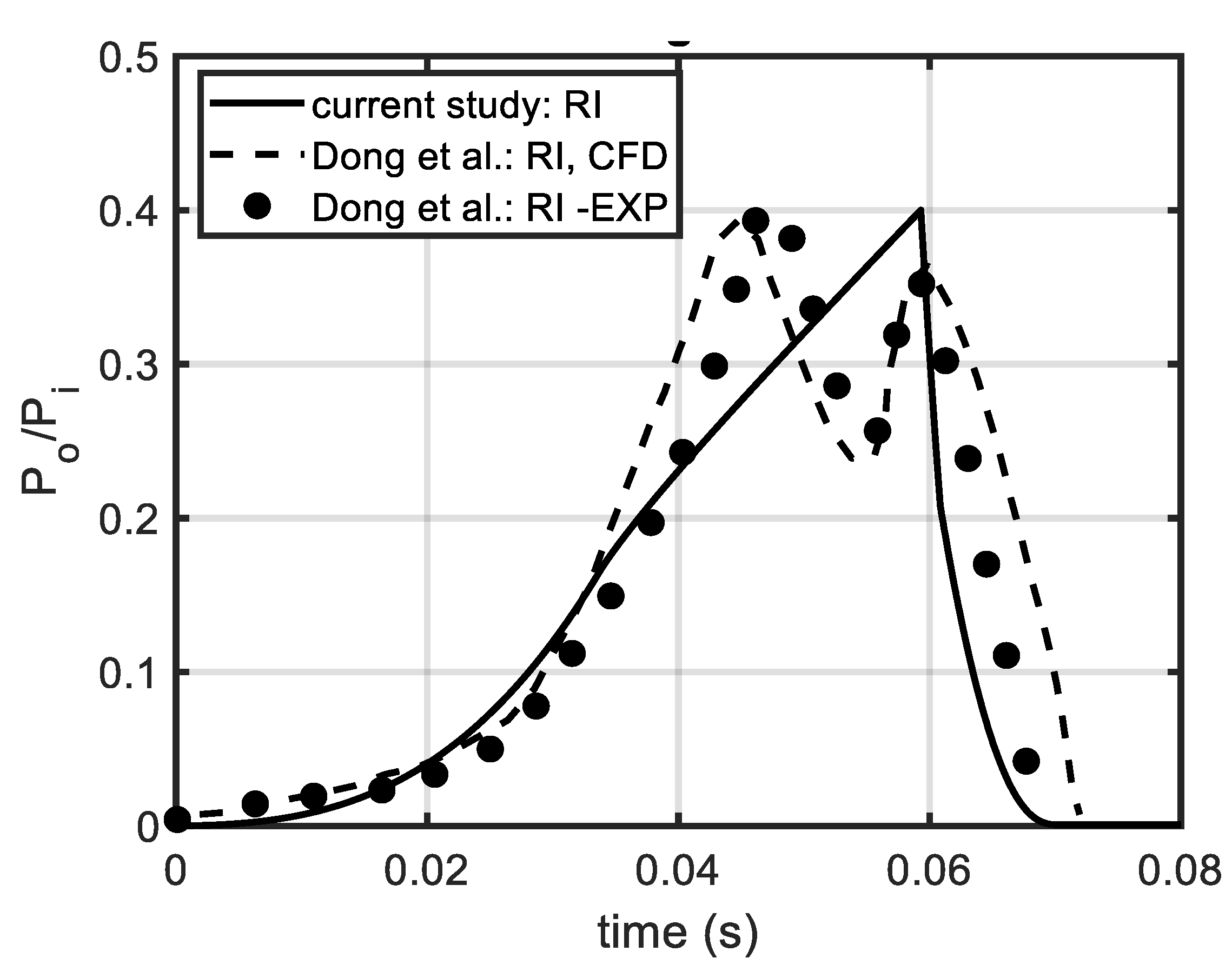
In the past, Dong et al. [
19] reported a combined experimental and computational investigation of vented explosions of a hydrogen-air mixture in a cylinder of length 100 cm and diameter 18 cm. Consequently, we started the present work with employing the EVA to predict the pressure of hydrogen-air explosions in such a cylindrical enclosure. The initial conditions were taken as
atm and
.
Figure 3 compares the EVA results with the experimental data and the CFD modelling of [
19]. Specifically, time evolution of the scaled pressure,
, in the case of rear ignition (RI) is depicted in
Figure 3, with good agreement between the EVA and Ref. [
19] seen.
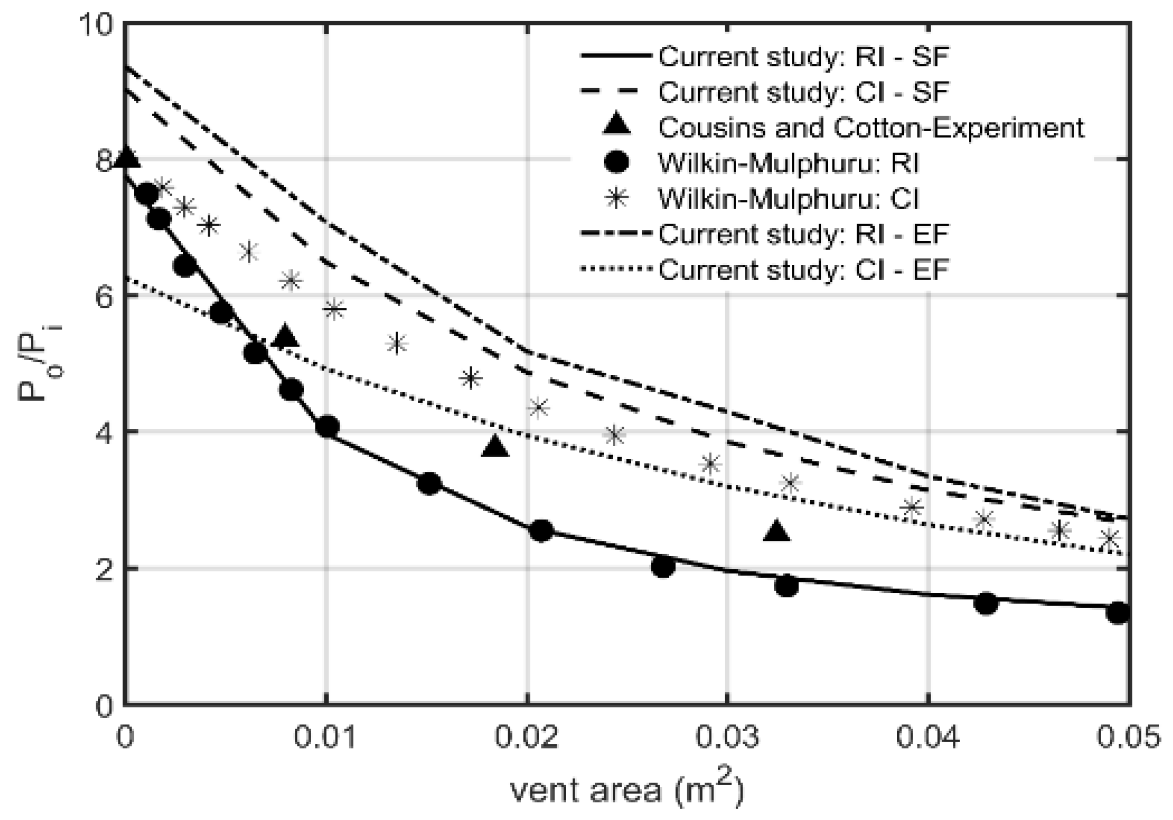
In addition, we have tested how the flame shape and the ignition location influence the accuracy of the EVA predictions. This is shown in
Figure 4, where the maximum peak pressures are presented versus the vent area, with two options for the flame morphology—the spherical flame (SF) shape and the ellipsoidal flame (EF) shape—considered for both central ignition (CI) and rear ignition (RI). Here, the EVA results are compared with the experimental data, shown by the markers in this figure. Again, we see good agreement between the EVA and the experiments in
Figure 4. More details about these simulations can be found in Ref. [
21].
Unlike
Figure 3 and
Figure 4, devoted to hydrogen-air explosions, in the present work we mainly focus on vented explosions of a stoichiometric methane-air mixture, with various vent areas considered. The model configuration imitates that of Ref. [
22], with RI employed as the location of ignition. Below, the corresponding pressure evolutions will be shown and validated by the experiments [
22].
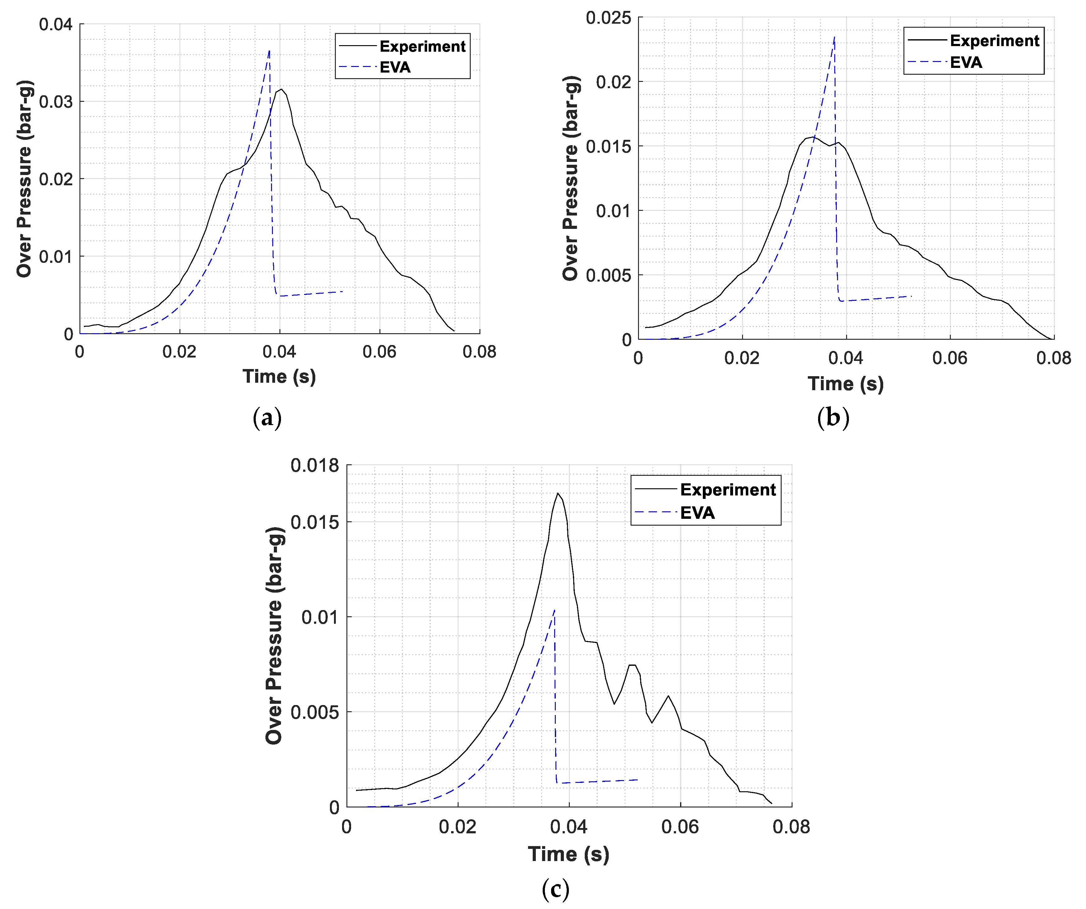
3.1. Pressure Evolution
Figure 5 shows the overpressure versus time for various vent areas, namely,
67.9 cm
2, 86.6 cm
2, and 132.7 cm
2 in
Figure 5a–c, respectively. In all three cases, the EVA predictions are validated by the experiments [
22]. Specifically, in
Figure 5a, the transient pressure, recorded from the experiment, and the EVA simulation results matched initially at the onset. Quantitatively, the peak pressure were 0.036 bar-g and 0.031 bar-g for the EVA and the experiments, respectively. While the maximum overpressure from the EVA appeared 14% higher than that reported in the experiments; in fact, such an over-prediction is good for safety purposes (the key point of the EVA is to predict the worst scenario and to not underestimate the risks). The EVA simulations attained the maximum overpressure quicker as compared to the experiments, which shows some timing discrepancy. It is also noted that after attaining the maximum overpressure, the pressure history results from the EVA stopped matching the experimental results; such a deviation can be due to combustion instabilities or other factors from the experiments not accounted in the EVA.
Figure 5b is a counterpart of
Figure 5a for the medium vent area,
86.6 cm
2. Both figures demonstrate qualitatively similar trends. The maximum overpressures for the middle vent case,
Figure 5b, are 0.023 and 0.015 bar-g from the EVA and the experiments, respectively. Here, the EVA over-predicted the experimental values peak pressure by 53%—much stronger as compared to the 14% in the small vent case,
Figure 5a. Regarding
Figure 5b, it is also noted that the time the EVA attained the peak pressure fits the experiment peak pressure time well. We also observe that the EVA transient pressure results of
Figure 5b match the experimental values until the peak pressure is attained; thereafter, the EVA pressure results dropped and transitioned to an almost constant value.
Finally, when the vent area has been further increased, to
132.7 cm
2 (the large vent case,
Figure 5c), the EVA pressure history and timing generally match the experimental results before attaining the peak pressure. Quantitatively, the EVA predicted the overpressure of 0.010 bar-g in this case, while the experimental value was 0.016 bar-g.
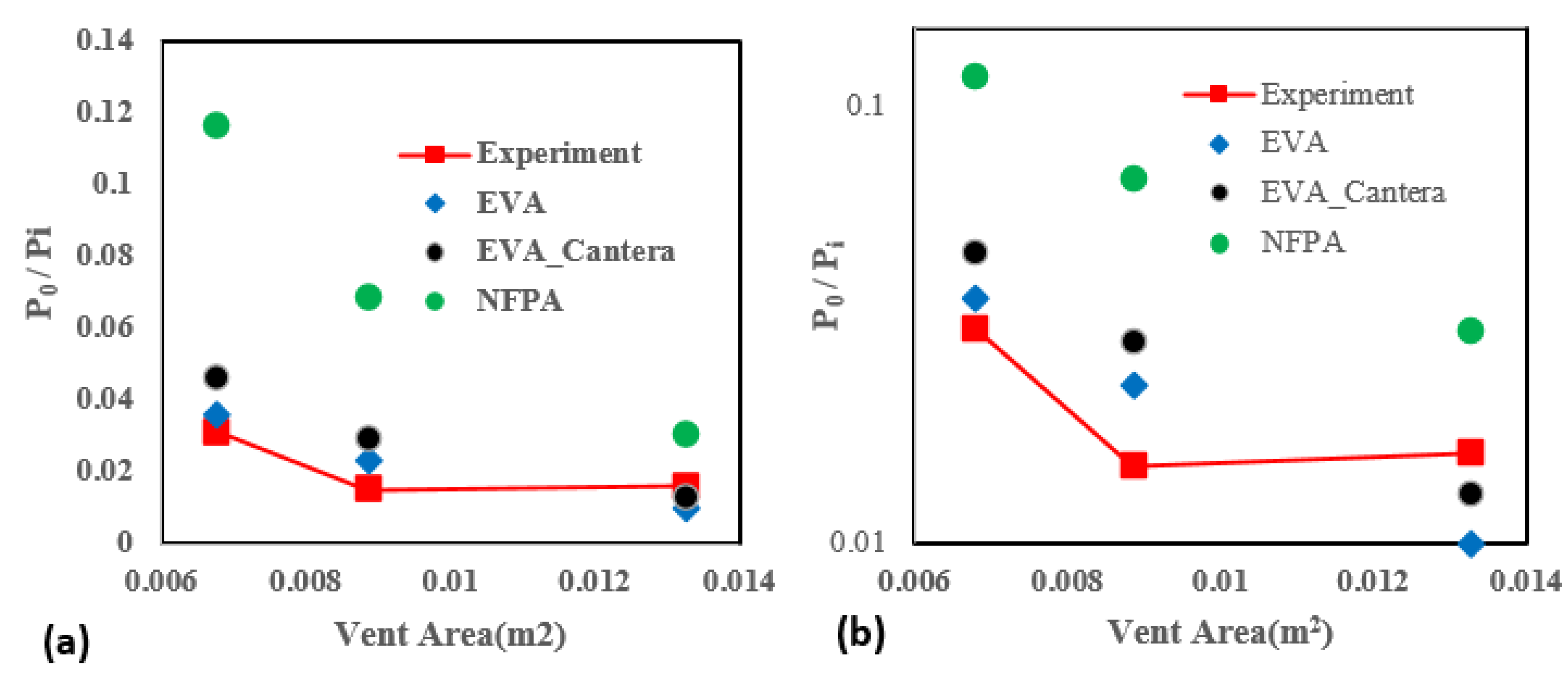
3.2. Maximum Overpressure
It is recalled that the Cantera software has been integrated with the EVA—in order to be able to compute the laminar flame speeds by means of Cantera and, thereby, provide an alternative to the laminar flame velocity correlations originally used in the EVA. This integration was implemented at the very beginning of the present study in order to enhance the versatility of the EVA code, making it able to be used for a wider range of fuels.
Figure 6 compares the peak pressures obtained from the original EVA (blue) as well as from the EVA with Cantera (black) with those from the experiments [
22] (red) for various vent areas. The results calculated by means of the NFPA 68 standards [
32] are shown by the green circles. The results are presented in both the normal,
Figure 6a, and the semi-logarithmic,
Figure 6b, scales. It is visually seen from
Figure 6 that the EVA predictions generally agree with the experiments [
22]. Moreover, it is clearly seen that both EVA cases (with and without Cantera) show much better agreement with the experiments [
22] than the NFPA 68 standards. The corresponding peak pressure values as well as the errors of the approaches are tabulated in
Table 1. It is seen that the EVA-Cantera model yields higher overpressures than the original EVA. Obviously, this is because Cantera provided the higher laminar burning velocity value as compared to the original EVA correlations. It is seen that it was particularly beneficial to use the integrated EVA-Cantera model for the large vent area case,
132.7 cm
2: the EVA-Cantera model predicted the experimental peak pressure better than the original EVA model in this case. In contrast, for other two cases of the medium and small vent areas, 86.6 cm
2 and 67.9 cm
2, the original EVA model predicted the experiments [
22] better than the integrated EVA-Cantera.
4. Conclusions
The present work showcased the capability of using the Explosion Venting Analyzer (EVA) model [
20,
21] to predict the pressure evolution in the process of methane-air mixture explosions in vented cylindrical vessels. The EVA results are validated by the experimental measurements [
19,
22]. It is shown that the EVA over-predicts the peak pressure for small and medium vent area of 67.9 cm
2 and 86.6 cm
2 but under-predicts the peak pressure when the vent area is as large as 132.7 cm
2. This might have resulted from the combustion instabilities or other factors not accounted by the EVA. Regarding the pressure evolution with time, for a small vent, 67.9 cm
2, the EVA predicted faster pressure raise than that in the experiments [
22], while for the 86.6 cm
2 and 132.7 cm
2 vent areas, the EVA results generally agree with the experimental data. Also, Cantera was integrated with the EVA to compute the laminar flame velocity. As a result, the EVA-Cantera model predicts higher overpressure as compared to the original EVA. Overall, the EVA is proven to be an acceptable model as its results have good match with the experimental values. This therefore demonstrate the usability of the EVA in determining the peak pressures of gas explosions in cylindrical enclosure.


 ,
, 


