1. Introduction
Despite the fact that the effects of earthquake duration to damage of structures are well known [
1], current seismic codes, e.g., Eurocode 8 [
2], still make use only of spectral acceleration in order to define the design seismic load. The response/design spectrum is a snapshot of the total seismic response, providing the maximum value of the response index (displacement, velocity, acceleration) needed for a particular structure (in terms of its natural period) of interest considering its elastic or inelastic behavior. However, the number of times that this maximum value of response occurs remains unanswered when using a response/design spectrum even though some attempts have been made towards the inclusion of duration (number of cycles) in its definition, e.g., [
3,
4].
The duration is an important characteristic of earthquake ground motion and affects both the structural response and response of soils. In particular, prolonged duration of earthquake ground motion is the decisive factor related to the fatigue and deterioration/degradation phenomena of structures and to the liquefaction and permanent displacements of soils. According to Trifunac and Novikova [
5], the duration of earthquake ground motion depends on: (i) the duration of the rupture process (involves the released seismic energy, the ruptured area, the velocity of rupture and the shear wave velocity of the medium); (ii) the propagation path effects (through rocks or soft sediments); (iii) regional effects (topographic irregularities, trapped waves in a sedimentary basin) and (iv) local soil effects (geology of the recoding site).
Very strong (in terms of their moment magnitude) earthquakes occurring at the broader area of subduction zones, essentially produce strong ground motion with long duration as a result of the rupture process. As most recent examples of these earthquakes, one can mention the 2010 Maule, Chile and the 2011, Tohoku-Oki, Japan 2011 earthquakes. It is also important to point out that after the aforementioned earthquakes, a large number of long duration accelerograms have been added to the worldwide long duration strong ground motion database. The usual procedure followed in regions exposed to earthquakes induced at subduction zones—but for them very limited or no historical strong ground motion recording is available (e.g., the cities of Seattle and Portland in USA)—is to construct design spectra or even artificial strong ground motions, e.g., [
6,
7] utilizing advanced models to simulate the anticipated earthquakes. By doing this, the collapse risk of the buildings in those regions can be assessed [
8]. On the other hand, seismic waves that emanate from earthquakes initiated at subduction zones may travel large distances and instead of being reduced in amplitude, they are amplified due to the regional and/or local site effects, thus increasing the duration of the earthquake shaking at a site. The 1985, Michoachan, Mexico earthquake is a unique representative of this phenomenon and the recorded duration of strong ground motion was between 60 and 180 s in various parts of Mexico City lakebed area [
9].
So far, the seismic performance of various steel structures subjected to long duration seismic motions has been severely tested only in the cases of the 1985 Michoachan, Mexico, the 2010 Maule, Chile and the 2011 Tohoku-Oki, Japan earthquakes [
10,
11,
12,
13]. Taking into account that: (i) the use of steel is not a common construction option in many regions or countries where potential earthquakes from subduction zones pose a significant threat; (ii) the absence of historical recordings of long duration seismic motions in many regions or countries where steel structure is a common construction option and potential earthquakes from subduction zones pose a significant threat; (iii) long duration seismic motions may dominate the seismic hazard associated with the long period structures in regions or countries close or even far away from the area of subduction zones; the engineering community exhibits a growing interest in performing numerical studies of steel structures (moment resisting frames, concentrically braced frames, dual moment resisting braced frames) subjected to long duration seismic motions [
14,
15,
16,
17,
18,
19,
20]. In these studies, the state-of-the-art modeling for fracture due to low cycle fatigue in conjunction with strength/stiffness deterioration of components due to the large number of loading reversals is utilized. The variation of the modeling parameters in seismic response results has been also recently investigated using sensitivity analysis [
21]. The main finding from the aforementioned studies [
14,
15,
16,
17,
18,
19,
20,
21] is that long duration earthquakes may induce significant damage accumulation at some storeys, due to the fracture of several steel braces, and thereby alter the collapse safety of the steel structures.
In [
14,
15,
16,
17,
18,
19,
20,
21], the steel building structures studied were assumed to be fixed base and, thus, soil–structure interaction (SSI) effects are not modeled. However, on the assumption of compliant ground, SSI affects both the seismic response and collapse potential of steel structures subjected to long duration motions. Up to now, the seismic response of 3D steel structures founded on compliant ground and subjected to long duration seismic motions has not been sufficiently studied. Therefore, the purpose of this study is to address this issue by assessing the seismic performance of 3D steel buildings and their foundations (i.e., steel-building foundation systems), for the case of long duration seismic motions.
In particular, following the provisions of Eurocodes 3, 7 and 8 [
2,
22,
23,
24], three low-rise steel structure-foundation systems are designed initially as fixed base and then with SSI included. The seismic performance of these steel-building foundation systems is then assessed by means of nonlinear dynamic (time-history) analyses performed in SAP 2000 [
25]. A set of 11 historical accelerograms recorded during earthquakes that took place in specific subduction zones and exhibiting a pronounced long duration, were employed for these seismic analyses. The seismic performance assessment involves the computation of the maximum values for: (i) the interstorey and residual interstorey drift ratios (IDR and RIDR, respectively), overturning moments and base shears (
Mb and
Vb, respectively) of the steel buildings and (ii) the residual settlement
δ and tilting
ω of the foundations. The maximum values obtained for RIDR,
δ,
ω are then compared to the maximum permitted ones [
26,
27]. In order to demonstrate the degree to which SSI affects the overall seismic response of the steel structure-foundation systems, a comparison of the aforementioned maximum values is presented. SSI is modeled by a discrete mass–stiffness–dashpot system that does not depend on the frequency of the seismic excitation, and its parameters are calculated using simple formulas that depend on the geometry of the foundation and the properties of the underlying and surrounding soil [
28].
It is concluded that the seismic performance of steel buildings designed following the provisions of Eurocode 8 [
2] when subjected to long duration seismic motions is: (i) acceptable for the two and five-storey fixed base steel buildings and for the two-storey steel buildings with SSI effects included; (ii) unacceptable for the eight-storey fixed base steel buildings and for the five and eight-storey steel buildings with SSI effects included. In all cases of steel buildings with SSI effects included, the seismic performance of the mat foundation, as expressed by the computed values of residual settlement
δ and tilting
ω, is always acceptable.
The results of this work are deemed to be realistic and can be viewed, even for comparison purposes, in conjunction with those obtained by Katsimpini et al. [
29] for the case of near-fault seismic motions. It is recalled that Eurocode 8 [
2], in its current version, does not provide a specific methodology for the analysis and design of steel building-foundation systems, considering or neglecting SSI, in regions where the potential seismic hazard from long duration seismic motions is high or even dominates. A similar deficiency in Eurocode 8 [
2] has been pointed out by Katsimpini et al. [
29] for the case of near-fault seismic motions.
2. Steel Building-Foundation Systems Studied
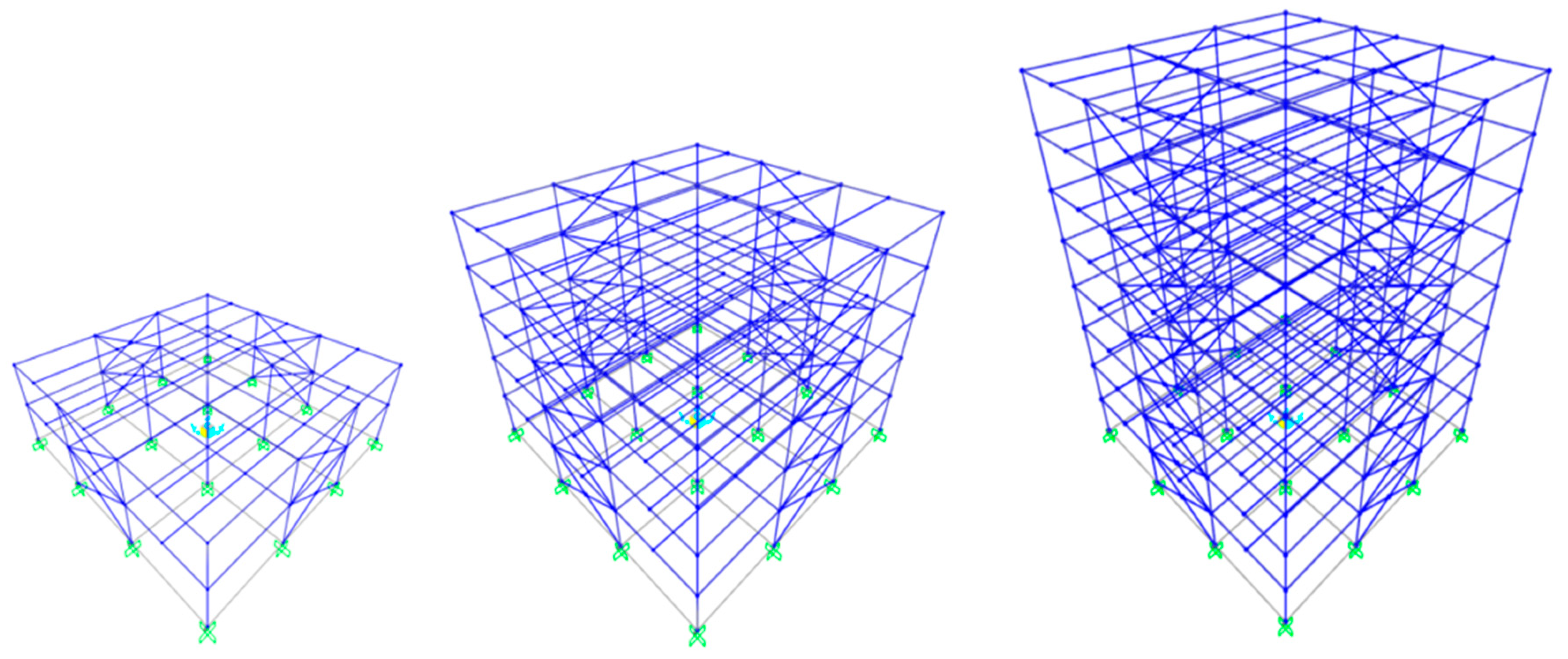
The two-, five- and eight-storey low-rise steel buildings, shown in
Figure 1, are studied herein. These buildings are regular in plan (in both orthogonal directions there are three bays of 6 m span each) and elevation (each storey has a height of 3 m). At each floor level a rigid composite slab is considered, and the values assumed for dead and live loads are 8 kN/m
2 and 3 kN/m
2, respectively. The plan view along with the layout (orientation) of columns is shown in
Figure 2.
The steel buildings are initially designed as fixed base dual steel structures, i.e., comprised by moment-resisting and concentrically braced frames (dual MRF–CBF), following Eurocodes 3 [
22] and 8 [
2]. The yield strength of the columns is 355 MPa, whereas that of beams and braces is 235 MPa and 275 MPa, respectively. All connections between main beams and columns are designed as moment-resisting ones. Simple shear connections are assigned to the ends of the secondary floor beams and pinned connections to the ends of the braces. The braces intersect at their mid length and are simulated as fixed in plane directions and pinned in out of plane directions. The design spectrum of Eurocode 8 [
2] for a peak ground acceleration (PGA) equal to 0.36 g, behavior (force reduction) factor equal to 3 and soil class B, is considered for the calculation of the design seismic load. The sections of steel members obtained after the implementation of the necessary design load combinations, are given in
Table 1.
For the two, five and eight-storey steel buildings in
Figure 1, the foundation type selected is that of a rigid mat having an area 20 × 20 m and thickness of 0.3 m, 0.6 m and 0.8 m, respectively. The rigid mat foundations have been designed according to Eurocode 8 [
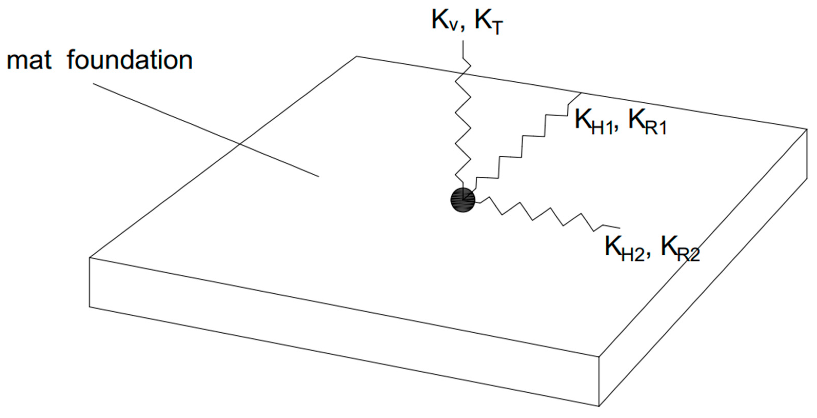
24]. SSI is now introduced to the numerical model of the steel buildings in
Figure 1, upon the assumption that the mat foundation is constructed on a soil of class C or D, according to the soil classification adopted in [
2]. More specifically, a set of masses–dashpots–springs, indicatively shown in
Figure 3, is assigned to all six modes of vibration of the mat foundation [
28]. This set is assumed to act at the center of the mat foundation. It should be noted that in
Figure 3, only the horizontal (
), vertical (
rocking
) and torsional (
) springs are shown. Masses and dashpots are not shown in
Figure 3 but they essentially accompany each separate spring, e.g., horizontal masses
and dampers
etc. To calculate the values of mass-damping-stiffness parameters associated with each mode of vibration (i.e., two horizontal, one vertical, two rocking and one torsional) of the mat foundation,
Table 2, taken from [
28], is provided.
The set of formulas presented in
Table 2 cannot be used when the embedment depth of the foundation is significant, i.e., greater than 2 m. Obviously this is not the case herein but if it was, one would simply make use of similar formulae from the literature where the embedment depth is included. On the other hand, because of the small depth (embedment) of the mat foundation considered herein, effects of kinematic interaction SSI can be omitted. One other thing to note about the set of formulas of
Table 2, is that special phenomena of slippage or uplift met in the soil–foundation interface are not included in their derivation. The consideration of these phenomena requires the use of a special set of masses–dashpots–springs that can be found in the relevant literature. Nevertheless, these phenomena were out of the scope of this work.
Following the soil classification of Eurocode 8 [
2] and soil class A as a benchmark, the contribution of SSI is expected to be significant for soil classes C and D and marginal for soil class B—which is the one used for the initial (fixed base) design of the steel buildings shown in
Figure 1. Therefore, it is assumed that, practically, soil class B represents fixed base conditions. To calculate the mass–damping–stiffness parameters for the soil classes C and D, which were chosen herein for the SSI considerations to the steel buildings of
Figure 1, one needs representative values for the shear wave velocity
Vs and soil density
ρ associated with these types of soils. These values are shown in
Table 3. Eurocode 8 [
24] provides a further reduction to the shear modulus
G obtained using the nominal values of
Vs and
ρ. This reduction depends on the ground acceleration ratio (PGA times the soil factor) and aims to capture the stiffness of soil at small strain levels (nonlinear behavior). Thus, for PGA = 0.36 g and soil factors equal to 1.15 and 1.35 for soil class C and D, respectively, the effective shear modulus
Geff to be used in
Table 2 is conservatively assumed to be 0.16
G [
24].
The design of steel buildings of
Figure 1 with SSI included (via the set of masses–dashpots–springs presented above) is performed using the design spectrum of Eurocode 8 [
2] (for PGA equal to 0.36 g, and behavior (reduction) factor equal to 3) that corresponds first to soil class C, and then to soil class D. The sections of steel members finally obtained for these soil class cases are the same as those given in
Table 1 for soil class B (fixed base conditions), even though the stress ratios calculated from the interaction (member design) equations of [
22] are different for each one of the soil classes considered. The only exception is the assignment of HEM 700 columns to the five-storey steel building for soil classes C and D.
The set of long duration accelerograms used for the non-linear time-history analyses is shown in
Table 4. In this table some details associated with the recorded accelerograms, i.e., the earthquake name, location, year and moment magnitude, are also provided. The two horizontal components of these accelerograms are applied to structural axes of
Figure 2 with varying angle of seismic incidence
θ, i.e., 0°, 45° and 90°. Thus, the number of nonlinear time-history analyses performed for each one of the steel buildings of
Figure 1 is 99 (11 accelerograms × 3 values of
θ × 3 base-soil conditions). The accelerograms of
Table 4 have been taken from specific web sites of strong-motion data [
30,
31,
32] and they have been used as-recorded (their baseline-corrected versions) in nonlinear time-history analyses, i.e., they were neither scaled nor matched to a design spectrum. The 5%-damped response spectra [
2,
33] of the two horizontal components of the accelerograms of
Table 4 are shown in
Figure 4. In that figure, the mean spectrum from the individual 5%-damped spectra as well as the design spectra of Eurocode 8 [
2] for soil classes B, C, and D, are also provided for comparison purposes. It is stressed that the mean spectrum suppresses (as a result of averaging the dissimilar 5%-damped spectra) the real acceleration ordinates at periods >0.5 s and this effect should not be disregarded especially when SSI is to be evaluated.
The nonlinear dynamic time-history analyses are executed using SAP 2000 [
25], considering both material and geometrical non-linearities. More specifically, the system of equations of motion solved for each non-linear structure has the form
, where
,
,
are the mass, damping, stiffness matrices,
,
,
are the displacement, velocity and acceleration vectors and
the seismic motion (accelerogram). Geometrical and material non-linearities are considered in the stiffness term of the aforementioned system of equations. More specifically, with respect to geometric non-linearities, the geometric stiffness of each element is recomposed at each time step based on the current deformed geometry. Material nonlinearities, i.e., the spread of plasticity along the element length, is taken into account by employing the plastic hinge formulation. Non-linear coupling between elements is considered upon formation of the global stiffness matrix. This system is solved by stepwise time integration [
33].
Beams and columns are modeled as standard frame elements assuming concentrated plastic hinges at their ends. For the case of columns, plastic hinges are formed as a result of the interaction between axial load and biaxial bending while for the case of beams, plastic hinges are formed as a result of uniaxial bending only. To account for the effects of stiffness/strength degradation in beams and columns, the monotonic backbone curves and the moment-rotation (
Μ-
θ) curves proposed by Lignos and Krawinkler [
34] and Lignos et al. [
35] are implemented in [
25] in order to describe the behavior of the concentrated plastic hinges. The limits of permissible plastic rotations of the plastic hinges are those defined in ASCE 41-17 [
36] for specific seismic performance levels.
For reasons of keeping the analyses simple and at a reasonable time level, the steel braces are modeled as truss elements to which concentrated plastic hinges with isotropic strain hardening are assigned to their ends and at their intersection. In particular, experiments have shown that braces from the hollow section are susceptible to fracture at their mid span or intersection. Instead of using advanced simulation models that capture the fracture of the braces, e.g., [
37], it was decided to use plastic hinge (brace end) rotation as an index of the fracture of the brace, in accordance to [
38].
The empirical formula provided in [
38] essentially makes use of the brace end rotation in order to estimate the fracture of rectangular hollow sections. However, Kumar and Sahoo [
39] have shown that if the slenderness of a brace made with a circular hollow section is between 90–170, then the formula developed in [
38] holds and provides an indication of the fracture of the brace. The formula of [
38] can be conservatively used for fracture evaluation purposes even for brace slenderness values well below 90 [
39]. Nevertheless, an upper bound of 0.25 rad has to be set to the formula of [
38] in order to be consistent with the results of [
37]. The fracture of the braces is certainly affected by their connections (gusset plates) as well as by the strains induced in the middle of the brace (due to its out-of-plane movement). According to [
38], due to the X-bracing configuration, large brace end rotations and hence prior initiation of fracture and local buckling are expected. An initial out-of-plane camber of the braces and their gusset plate connections to the frame are not modeled in view of a future investigation even though they certainly influence the brace end rotation.
The innate viscous damping ratio of the steel buildings is assumed to be 3% for the first and the last significant mode of response [
33]. The “Link element” of SAP 2000 [
25] is used to simulate the set of masses–dashpots–springs [
28] that accounts for the inclusion of SSI in seismic analyses. The seismic time-history analyses are initially performed for the steel buildings with fixed base conditions and then for the steel buildings on compliant ground (soil classes C or D) where SSI is taken into account.
3. Seismic Performance Assessment
The seismic performance of the steel building-foundation systems under study when subjected to the long duration seismic motions in
Table 4 is deemed as acceptable or unacceptable if the following criteria are satisfied or not: (i) the plastic hinge rotations of the bottom storey columns and of all storey beams are lower than the life-safety (LS) level [
36] and there is no formation of a soft-storey mechanism; (ii) the maximum value computed for the RIDR does not surpass the threshold value of 0.5% [
26]; (iii) yielding of the braces takes place first and in line with the design principles. Brace fracture is an anticipated failure and it is traced by checking if the brace end rotation surpassed the value provided by the empirical formula of [
38]; (iv) the permissible level of deformation associated with the mat foundation, i.e., its residual settlement
δ and tilting
ω, is defined by the moderate damage limits of [
27]. The number of cases in which one or more of the above-mentioned criteria is violated, are considered as failures of the steel building-foundation system examined. It is made clear that these failures may be attributed to the steel building or to the foundation or to both.
To evaluate the effect of soil–structure interactions to the dynamic response of the steel structure-foundation systems under study, the index
K is introduced. This index is defined as the ratio of
KSSI to
KFIX, where
K is the maximum value of the parameter chosen, i.e., IDR, RIDR,
Vb or
Mb. A dash (-) is denoted where, by definition, the
K index cannot be calculated. Values for
Vb and
Mb are provided for the two orthogonal structural axes X and Y of
Figure 2, whereas only the maximum values for IDR and RIDR are presented irrespectively the structural axe in which they appear. One thing to note is that for the calculation of the interstorey displacements of the steel buildings founded on compliant ground (soil classes C and D), the rotation of the foundation is excluded. Finally, for the SSI cases,
Vb is calculated by summation of damping and elastic forces, whereas for the fixed base cases, by the elastic force.
3.1. Two-Storey Steel Building-Foundation Systems
The total number of failure cases for the two-storey steel building-foundation systems under the action of the 11 long duration earthquakes of
Table 4, including the three values considered for the angle of seismic incidence
θ, are presented in
Table 5. More specifically, it has been found out that the fixed base steel buildings fail in a total of three out of 33 cases studied, whereas the steel buildings founded on soil classes C and D, do not fail in any of the 66 cases studied. It should be also noted that in nine out of 33 cases, the fixed base steel buildings respond elastically, whereas the steel buildings founded on soil classes C and D exhibit elastic response in only two out of 66 cases.
The maximum values computed for residual settlement δ and tilting ω of the mat foundation are δ = 6.6 × 10⁻³ (soil class C), δ = 1.57 × 10⁻² (soil class D), ω = 5.4 × 10⁻⁴ (soil class C) and ω = 1.08 × 10⁻³ (soil class D). Therefore, the mat foundation exhibits no damage.
Disregarding the previously mentioned failure and elastic response cases,
Table 6 and
Table 7 display the maximum values of IDR, RIDR,
Vb and
Mb for the three values of
θ. In these tables, the values of the
K index are also presented. Interpreting the values of the
K index, one realizes that the effect of SSI is negligible for
Vb and
Mb but is significant for IDR and RIDR. The maximum value computed for the brace end rotation is 0.051 rad, indicating no fracture in view of the maximum permissible value of 0.133 rad obtained using the formula of [
37]. Only in the three aforementioned failure cases, did the brace end rotation surpass this value of 0.133 rad.
3.2. Five-Storey Steel Building-Foundation Systems
The total number of failure cases for the five-storey steel building-foundation systems under the action of the 11 long duration earthquakes in
Table 4, including the three values considered for the angle of seismic incidence
θ, are presented in
Table 8. According to this table, the fixed base steel buildings fail in a total of one out of 33 cases studied, whereas the steel buildings founded on soil classes C and D, fail in 42 out of 66 cases studied. Moreover, in three out of 33 cases, the fixed base steel buildings respond elastically, whereas the steel buildings founded on soil classes C and D never exhibit an elastic response.
The maximum values computed for residual settlement δ and tilting ω of the mat foundation are δ = 1.56 × 10⁻² (soil type C), δ = 3.75 × 10⁻² (soil type D), ω = 9.6 × 10⁻⁴ (soil type C) and ω = 2.02 × 10⁻³ (soil type D). These values indicate that the mat foundation exhibits no damage.
Leaving aside the cases where failure or elastic response is observed,
Table 9 and
Table 10 display the maximum values of IDR, RIDR,
Vb and
Mb for the three values of
θ, along with the values of the
K index. On the basis of these values of
K index, it seems that the effect of SSI is favorable for
Vb,
Mb and RIDR, even though it increases IDR. However, these reduced
Vb,
Mb and RIDR values must be viewed with extreme caution in view of the fact that, as mentioned above, the percentage of failure of the five-storey steel building including SSI is high, i.e., 42/66 = 63.6%. The maximum value computed for the brace end rotation is 0.11 rad, indicating no fracture in view of the maximum permissible value of 0.122 rad obtained using the formula of [
37]. It is stressed that in all 42 failure cases identified, at least four braces fractured, i.e., the brace end rotation surpassed the value of 0.122 rad calculated by the formula of [
37].
3.3. Eight-Storey Steel Building-Foundation Systems
The total number of failure cases for the eight-storey steel building-foundation systems under the action of the 11 long duration earthquakes of
Table 4, including the three values considered for the angle of seismic incidence
θ, are presented in
Table 11. According to the results shown in this table, the fixed base steel buildings fail in a total of 24 out of 33 cases studied, whereas the steel buildings founded on soil classes C and D, fail in 54 out of the 66 cases studied.
The maximum values computed for residual settlement, δ, and tilting, ω, of the mat foundation are δ = 2.8 × 10⁻² (soil type C), δ = 6.6 × 10⁻² (soil type D), ω = 1.92 × 10⁻³ (soil type C) and ω = 3.91 × 10⁻³ (soil type D). In view of these values for δ and ω, the mat foundation exhibits no damage.
Excluding the cases where failure or elastic response is observed,
Table 12 and
Table 13 display the maximum values of IDR, RIDR,
Vb and
Mb for the three values of
θ, along with the values of the
K index. On the basis of these values of
K index, it seems that the effect of SSI is negligible for
Vb,
Mb and significant for IDR and RIDR. Nevertheless, as mentioned above, the percentage of failure of the eight-storey steel building including SSI is very high, i.e., 54/66 = 81.8%, thus, these
K values should be viewed with extreme caution. The maximum value computed for the brace end rotation is 0.067 rad indicating no fracture in view of the maximum permissible value of 0.109 rad obtained using the formula of [
37]. It should be stressed that in all 54 failure cases identified, at least eight braces fractured, i.e., the brace end rotation surpassed the value of 0.109 rad calculated by the formula of [
37].
4. Discussion
On the basis of the findings produced in the former section, the seismic performance of steel building-foundation systems, designed according to provisions of Eurocode 8 [
2], when subjected to long duration earthquakes, is mixed with respect to the steel building and base conditions considered. In particular, the two and five-storey fixed base steel buildings and the two-storey steel buildings on compliant ground (soil classes C and D) exhibit very good seismic performance. On the other hand, the eight-storey fixed base buildings and the five and eight-storey steel buildings on compliant ground (soil classes C and D) exhibit poor seismic performance. This poor performance is depicted by the large number of failures induced, as shown in
Table 5,
Table 8 and
Table 11.
The dominant type of failure observed is that of the formation of a soft-storey mechanism as a result of several simultaneous brace fractures in conjunction with major damage induced to the beams, i.e., the plastic hinge rotation of the beam ends surpassed the LS level [
36]. The prolonged duration of the seismic motion further leads to drift concentration at specific storeys, rendering the distribution of deformation demands to other storeys impossible. This drift concentration is mainly attributed to the lower overstrength or to the premature local buckling of some braces. In other words, to rely on the overstrength variation requirement of the braces according to Eurocode 8 [
2], does not seem to prevent the formation of a soft-storey mechanism [
40,
41]. Therefore, to avoid the occurrence of multiple premature brace fractures, a design parameter, e.g., the brace end rotation proposed in [
38], which accounts for low cycle fatigue is suggested to be adopted in the next version of Eurocode 8 [
2]. Alternatively, a computational model for low-cycle fatigue—calibrated to describe brace fracture—may directly be incorporated in the analysis of a steel building subjected to long duration motions [
16,
20]. Finally, even though it has been observed in [
29], premature yielding of columns before yielding of the braces was not met in any of the analyses performed herein.
As inferred from the maximum values computed for residual settlement
δ and tilting
ω, the mat foundations designed according to Eurocode 8 [
24] exhibited no damage and performed according to expectations. Even though, the computation of
δ and
ω stopped at the time point where the steel building exhibited obvious failure, it is the authors’ opinion that the design rules of mat foundation of Eurocode [
8] are adequate for the case of long duration earthquakes. Nevertheless, non-linear effects at the foundation-soil interface, i.e., uplift and slippage of the foundation, have not been addressed herein and may be investigated in view of a holistic performance assessment of the foundation.

 ,
, 


